EP2236423A2 - Method and apparatus for filling a fuel container - Google Patents
Method and apparatus for filling a fuel container Download PDFInfo
- Publication number
- EP2236423A2 EP2236423A2 EP10167699A EP10167699A EP2236423A2 EP 2236423 A2 EP2236423 A2 EP 2236423A2 EP 10167699 A EP10167699 A EP 10167699A EP 10167699 A EP10167699 A EP 10167699A EP 2236423 A2 EP2236423 A2 EP 2236423A2
- Authority
- EP
- European Patent Office
- Prior art keywords
- fuel
- adapter
- chamber
- connector
- supply
- Prior art date
- Legal status (The legal status is an assumption and is not a legal conclusion. Google has not performed a legal analysis and makes no representation as to the accuracy of the status listed.)
- Granted
Links
- 239000000446 fuel Substances 0.000 title claims abstract description 499
- 238000000034 method Methods 0.000 title claims description 15
- 238000011065 in-situ storage Methods 0.000 claims abstract description 8
- 238000004891 communication Methods 0.000 claims description 22
- 239000012530 fluid Substances 0.000 claims description 21
- 238000012546 transfer Methods 0.000 claims description 20
- 238000012544 monitoring process Methods 0.000 claims description 16
- 239000004973 liquid crystal related substance Substances 0.000 claims description 2
- OKKJLVBELUTLKV-UHFFFAOYSA-N Methanol Chemical compound OC OKKJLVBELUTLKV-UHFFFAOYSA-N 0.000 description 40
- 238000006243 chemical reaction Methods 0.000 description 8
- 239000001257 hydrogen Substances 0.000 description 8
- 229910052739 hydrogen Inorganic materials 0.000 description 8
- 229910000033 sodium borohydride Inorganic materials 0.000 description 8
- 239000012279 sodium borohydride Substances 0.000 description 8
- KWYUFKZDYYNOTN-UHFFFAOYSA-M Potassium hydroxide Chemical compound [OH-].[K+] KWYUFKZDYYNOTN-UHFFFAOYSA-M 0.000 description 7
- 239000007788 liquid Substances 0.000 description 7
- XLYOFNOQVPJJNP-UHFFFAOYSA-N water Substances O XLYOFNOQVPJJNP-UHFFFAOYSA-N 0.000 description 7
- 239000012528 membrane Substances 0.000 description 6
- 239000000203 mixture Substances 0.000 description 6
- 239000007800 oxidant agent Substances 0.000 description 6
- 230000001590 oxidative effect Effects 0.000 description 6
- 239000000126 substance Substances 0.000 description 6
- UFHFLCQGNIYNRP-UHFFFAOYSA-N Hydrogen Chemical compound [H][H] UFHFLCQGNIYNRP-UHFFFAOYSA-N 0.000 description 5
- LFQSCWFLJHTTHZ-UHFFFAOYSA-N Ethanol Chemical compound CCO LFQSCWFLJHTTHZ-UHFFFAOYSA-N 0.000 description 4
- 239000003054 catalyst Substances 0.000 description 4
- 229930195733 hydrocarbon Natural products 0.000 description 4
- 150000002430 hydrocarbons Chemical class 0.000 description 4
- 239000000463 material Substances 0.000 description 4
- 229910052751 metal Inorganic materials 0.000 description 4
- 239000002184 metal Substances 0.000 description 4
- BASFCYQUMIYNBI-UHFFFAOYSA-N platinum Chemical compound [Pt] BASFCYQUMIYNBI-UHFFFAOYSA-N 0.000 description 4
- 238000003860 storage Methods 0.000 description 4
- 238000006073 displacement reaction Methods 0.000 description 3
- 230000005611 electricity Effects 0.000 description 3
- 238000005370 electroosmosis Methods 0.000 description 3
- 230000005484 gravity Effects 0.000 description 3
- 239000002245 particle Substances 0.000 description 3
- 230000036647 reaction Effects 0.000 description 3
- MHAJPDPJQMAIIY-UHFFFAOYSA-N Hydrogen peroxide Chemical compound OO MHAJPDPJQMAIIY-UHFFFAOYSA-N 0.000 description 2
- NBIIXXVUZAFLBC-UHFFFAOYSA-N Phosphoric acid Chemical compound OP(O)(O)=O NBIIXXVUZAFLBC-UHFFFAOYSA-N 0.000 description 2
- ATUOYWHBWRKTHZ-UHFFFAOYSA-N Propane Chemical compound CCC ATUOYWHBWRKTHZ-UHFFFAOYSA-N 0.000 description 2
- XUIMIQQOPSSXEZ-UHFFFAOYSA-N Silicon Chemical compound [Si] XUIMIQQOPSSXEZ-UHFFFAOYSA-N 0.000 description 2
- QAOWNCQODCNURD-UHFFFAOYSA-N Sulfuric acid Chemical compound OS(O)(=O)=O QAOWNCQODCNURD-UHFFFAOYSA-N 0.000 description 2
- HCHKCACWOHOZIP-UHFFFAOYSA-N Zinc Chemical compound [Zn] HCHKCACWOHOZIP-UHFFFAOYSA-N 0.000 description 2
- 239000003513 alkali Substances 0.000 description 2
- 239000001273 butane Substances 0.000 description 2
- 239000006227 byproduct Substances 0.000 description 2
- 230000001413 cellular effect Effects 0.000 description 2
- 238000002485 combustion reaction Methods 0.000 description 2
- 239000008151 electrolyte solution Substances 0.000 description 2
- 238000005516 engineering process Methods 0.000 description 2
- 239000000945 filler Substances 0.000 description 2
- 230000006870 function Effects 0.000 description 2
- XLYOFNOQVPJJNP-ZSJDYOACSA-N heavy water Substances [2H]O[2H] XLYOFNOQVPJJNP-ZSJDYOACSA-N 0.000 description 2
- 150000002431 hydrogen Chemical class 0.000 description 2
- -1 i.e. Substances 0.000 description 2
- 230000013011 mating Effects 0.000 description 2
- 238000012986 modification Methods 0.000 description 2
- 230000004048 modification Effects 0.000 description 2
- IJDNQMDRQITEOD-UHFFFAOYSA-N n-butane Chemical compound CCCC IJDNQMDRQITEOD-UHFFFAOYSA-N 0.000 description 2
- OFBQJSOFQDEBGM-UHFFFAOYSA-N n-pentane Natural products CCCCC OFBQJSOFQDEBGM-UHFFFAOYSA-N 0.000 description 2
- 229910052697 platinum Inorganic materials 0.000 description 2
- 229920000642 polymer Polymers 0.000 description 2
- 238000002407 reforming Methods 0.000 description 2
- NVIFVTYDZMXWGX-UHFFFAOYSA-N sodium metaborate Chemical compound [Na+].[O-]B=O NVIFVTYDZMXWGX-UHFFFAOYSA-N 0.000 description 2
- 229910052725 zinc Inorganic materials 0.000 description 2
- 239000011701 zinc Substances 0.000 description 2
- OKTJSMMVPCPJKN-UHFFFAOYSA-N Carbon Chemical compound [C] OKTJSMMVPCPJKN-UHFFFAOYSA-N 0.000 description 1
- 239000004215 Carbon black (E152) Substances 0.000 description 1
- BVKZGUZCCUSVTD-UHFFFAOYSA-L Carbonate Chemical compound [O-]C([O-])=O BVKZGUZCCUSVTD-UHFFFAOYSA-L 0.000 description 1
- 102000004190 Enzymes Human genes 0.000 description 1
- 108090000790 Enzymes Proteins 0.000 description 1
- HBBGRARXTFLTSG-UHFFFAOYSA-N Lithium ion Chemical compound [Li+] HBBGRARXTFLTSG-UHFFFAOYSA-N 0.000 description 1
- 229910003252 NaBO2 Inorganic materials 0.000 description 1
- 229920000557 Nafion® Polymers 0.000 description 1
- KJTLSVCANCCWHF-UHFFFAOYSA-N Ruthenium Chemical compound [Ru] KJTLSVCANCCWHF-UHFFFAOYSA-N 0.000 description 1
- 239000000853 adhesive Substances 0.000 description 1
- 230000001070 adhesive effect Effects 0.000 description 1
- 150000001298 alcohols Chemical class 0.000 description 1
- 229910000147 aluminium phosphate Inorganic materials 0.000 description 1
- QVGXLLKOCUKJST-UHFFFAOYSA-N atomic oxygen Chemical compound [O] QVGXLLKOCUKJST-UHFFFAOYSA-N 0.000 description 1
- 229910052799 carbon Inorganic materials 0.000 description 1
- 230000000295 complement effect Effects 0.000 description 1
- 230000001186 cumulative effect Effects 0.000 description 1
- 238000009792 diffusion process Methods 0.000 description 1
- 239000003814 drug Substances 0.000 description 1
- 229940079593 drug Drugs 0.000 description 1
- 238000012377 drug delivery Methods 0.000 description 1
- 230000005684 electric field Effects 0.000 description 1
- 230000007613 environmental effect Effects 0.000 description 1
- 230000005284 excitation Effects 0.000 description 1
- 239000002803 fossil fuel Substances 0.000 description 1
- 239000003574 free electron Substances 0.000 description 1
- 239000002828 fuel tank Substances 0.000 description 1
- 239000007789 gas Substances 0.000 description 1
- 229910001416 lithium ion Inorganic materials 0.000 description 1
- 150000002739 metals Chemical class 0.000 description 1
- 238000013508 migration Methods 0.000 description 1
- 230000005012 migration Effects 0.000 description 1
- 239000001301 oxygen Substances 0.000 description 1
- 229910052760 oxygen Inorganic materials 0.000 description 1
- CFQCIHVMOFOCGH-UHFFFAOYSA-N platinum ruthenium Chemical compound [Ru].[Pt] CFQCIHVMOFOCGH-UHFFFAOYSA-N 0.000 description 1
- 239000005518 polymer electrolyte Substances 0.000 description 1
- 239000011148 porous material Substances 0.000 description 1
- 238000010248 power generation Methods 0.000 description 1
- 230000008569 process Effects 0.000 description 1
- 239000001294 propane Substances 0.000 description 1
- 238000005086 pumping Methods 0.000 description 1
- 239000000376 reactant Substances 0.000 description 1
- 238000004064 recycling Methods 0.000 description 1
- 230000004044 response Effects 0.000 description 1
- 229910052707 ruthenium Inorganic materials 0.000 description 1
- 238000007789 sealing Methods 0.000 description 1
- 239000007787 solid Substances 0.000 description 1
- 239000000243 solution Substances 0.000 description 1
- 238000009834 vaporization Methods 0.000 description 1
- 230000008016 vaporization Effects 0.000 description 1
- 230000000007 visual effect Effects 0.000 description 1
Images


Classifications
-
- H—ELECTRICITY
- H01—ELECTRIC ELEMENTS
- H01M—PROCESSES OR MEANS, e.g. BATTERIES, FOR THE DIRECT CONVERSION OF CHEMICAL ENERGY INTO ELECTRICAL ENERGY
- H01M8/00—Fuel cells; Manufacture thereof
- H01M8/04—Auxiliary arrangements, e.g. for control of pressure or for circulation of fluids
- H01M8/04082—Arrangements for control of reactant parameters, e.g. pressure or concentration
- H01M8/04201—Reactant storage and supply, e.g. means for feeding, pipes
- H01M8/04208—Cartridges, cryogenic media or cryogenic reservoirs
-
- H—ELECTRICITY
- H01—ELECTRIC ELEMENTS
- H01M—PROCESSES OR MEANS, e.g. BATTERIES, FOR THE DIRECT CONVERSION OF CHEMICAL ENERGY INTO ELECTRICAL ENERGY
- H01M8/00—Fuel cells; Manufacture thereof
- H01M8/04—Auxiliary arrangements, e.g. for control of pressure or for circulation of fluids
-
- F—MECHANICAL ENGINEERING; LIGHTING; HEATING; WEAPONS; BLASTING
- F17—STORING OR DISTRIBUTING GASES OR LIQUIDS
- F17C—VESSELS FOR CONTAINING OR STORING COMPRESSED, LIQUEFIED OR SOLIDIFIED GASES; FIXED-CAPACITY GAS-HOLDERS; FILLING VESSELS WITH, OR DISCHARGING FROM VESSELS, COMPRESSED, LIQUEFIED, OR SOLIDIFIED GASES
- F17C5/00—Methods or apparatus for filling containers with liquefied, solidified, or compressed gases under pressures
- F17C5/06—Methods or apparatus for filling containers with liquefied, solidified, or compressed gases under pressures for filling with compressed gases
-
- F—MECHANICAL ENGINEERING; LIGHTING; HEATING; WEAPONS; BLASTING
- F17—STORING OR DISTRIBUTING GASES OR LIQUIDS
- F17C—VESSELS FOR CONTAINING OR STORING COMPRESSED, LIQUEFIED OR SOLIDIFIED GASES; FIXED-CAPACITY GAS-HOLDERS; FILLING VESSELS WITH, OR DISCHARGING FROM VESSELS, COMPRESSED, LIQUEFIED, OR SOLIDIFIED GASES
- F17C7/00—Methods or apparatus for discharging liquefied, solidified, or compressed gases from pressure vessels, not covered by another subclass
-
- H—ELECTRICITY
- H01—ELECTRIC ELEMENTS
- H01M—PROCESSES OR MEANS, e.g. BATTERIES, FOR THE DIRECT CONVERSION OF CHEMICAL ENERGY INTO ELECTRICAL ENERGY
- H01M8/00—Fuel cells; Manufacture thereof
- H01M8/04—Auxiliary arrangements, e.g. for control of pressure or for circulation of fluids
- H01M8/04082—Arrangements for control of reactant parameters, e.g. pressure or concentration
- H01M8/04186—Arrangements for control of reactant parameters, e.g. pressure or concentration of liquid-charged or electrolyte-charged reactants
-
- H—ELECTRICITY
- H01—ELECTRIC ELEMENTS
- H01M—PROCESSES OR MEANS, e.g. BATTERIES, FOR THE DIRECT CONVERSION OF CHEMICAL ENERGY INTO ELECTRICAL ENERGY
- H01M8/00—Fuel cells; Manufacture thereof
- H01M8/04—Auxiliary arrangements, e.g. for control of pressure or for circulation of fluids
- H01M8/04082—Arrangements for control of reactant parameters, e.g. pressure or concentration
- H01M8/04201—Reactant storage and supply, e.g. means for feeding, pipes
-
- F—MECHANICAL ENGINEERING; LIGHTING; HEATING; WEAPONS; BLASTING
- F17—STORING OR DISTRIBUTING GASES OR LIQUIDS
- F17C—VESSELS FOR CONTAINING OR STORING COMPRESSED, LIQUEFIED OR SOLIDIFIED GASES; FIXED-CAPACITY GAS-HOLDERS; FILLING VESSELS WITH, OR DISCHARGING FROM VESSELS, COMPRESSED, LIQUEFIED, OR SOLIDIFIED GASES
- F17C2205/00—Vessel construction, in particular mounting arrangements, attachments or identifications means
- F17C2205/03—Fluid connections, filters, valves, closure means or other attachments
- F17C2205/0302—Fittings, valves, filters, or components in connection with the gas storage device
- F17C2205/0311—Closure means
-
- F—MECHANICAL ENGINEERING; LIGHTING; HEATING; WEAPONS; BLASTING
- F17—STORING OR DISTRIBUTING GASES OR LIQUIDS
- F17C—VESSELS FOR CONTAINING OR STORING COMPRESSED, LIQUEFIED OR SOLIDIFIED GASES; FIXED-CAPACITY GAS-HOLDERS; FILLING VESSELS WITH, OR DISCHARGING FROM VESSELS, COMPRESSED, LIQUEFIED, OR SOLIDIFIED GASES
- F17C2205/00—Vessel construction, in particular mounting arrangements, attachments or identifications means
- F17C2205/03—Fluid connections, filters, valves, closure means or other attachments
- F17C2205/0302—Fittings, valves, filters, or components in connection with the gas storage device
- F17C2205/0323—Valves
- F17C2205/0332—Safety valves or pressure relief valves
-
- F—MECHANICAL ENGINEERING; LIGHTING; HEATING; WEAPONS; BLASTING
- F17—STORING OR DISTRIBUTING GASES OR LIQUIDS
- F17C—VESSELS FOR CONTAINING OR STORING COMPRESSED, LIQUEFIED OR SOLIDIFIED GASES; FIXED-CAPACITY GAS-HOLDERS; FILLING VESSELS WITH, OR DISCHARGING FROM VESSELS, COMPRESSED, LIQUEFIED, OR SOLIDIFIED GASES
- F17C2205/00—Vessel construction, in particular mounting arrangements, attachments or identifications means
- F17C2205/03—Fluid connections, filters, valves, closure means or other attachments
- F17C2205/0302—Fittings, valves, filters, or components in connection with the gas storage device
- F17C2205/0323—Valves
- F17C2205/0335—Check-valves or non-return valves
-
- F—MECHANICAL ENGINEERING; LIGHTING; HEATING; WEAPONS; BLASTING
- F17—STORING OR DISTRIBUTING GASES OR LIQUIDS
- F17C—VESSELS FOR CONTAINING OR STORING COMPRESSED, LIQUEFIED OR SOLIDIFIED GASES; FIXED-CAPACITY GAS-HOLDERS; FILLING VESSELS WITH, OR DISCHARGING FROM VESSELS, COMPRESSED, LIQUEFIED, OR SOLIDIFIED GASES
- F17C2205/00—Vessel construction, in particular mounting arrangements, attachments or identifications means
- F17C2205/03—Fluid connections, filters, valves, closure means or other attachments
- F17C2205/0302—Fittings, valves, filters, or components in connection with the gas storage device
- F17C2205/0382—Constructional details of valves, regulators
- F17C2205/0385—Constructional details of valves, regulators in blocks or units
-
- F—MECHANICAL ENGINEERING; LIGHTING; HEATING; WEAPONS; BLASTING
- F17—STORING OR DISTRIBUTING GASES OR LIQUIDS
- F17C—VESSELS FOR CONTAINING OR STORING COMPRESSED, LIQUEFIED OR SOLIDIFIED GASES; FIXED-CAPACITY GAS-HOLDERS; FILLING VESSELS WITH, OR DISCHARGING FROM VESSELS, COMPRESSED, LIQUEFIED, OR SOLIDIFIED GASES
- F17C2227/00—Transfer of fluids, i.e. method or means for transferring the fluid; Heat exchange with the fluid
- F17C2227/01—Propulsion of the fluid
- F17C2227/0121—Propulsion of the fluid by gravity
-
- F—MECHANICAL ENGINEERING; LIGHTING; HEATING; WEAPONS; BLASTING
- F17—STORING OR DISTRIBUTING GASES OR LIQUIDS
- F17C—VESSELS FOR CONTAINING OR STORING COMPRESSED, LIQUEFIED OR SOLIDIFIED GASES; FIXED-CAPACITY GAS-HOLDERS; FILLING VESSELS WITH, OR DISCHARGING FROM VESSELS, COMPRESSED, LIQUEFIED, OR SOLIDIFIED GASES
- F17C2227/00—Transfer of fluids, i.e. method or means for transferring the fluid; Heat exchange with the fluid
- F17C2227/01—Propulsion of the fluid
- F17C2227/0128—Propulsion of the fluid with pumps or compressors
- F17C2227/0135—Pumps
- F17C2227/0142—Pumps with specified pump type, e.g. piston or impulsive type
-
- F—MECHANICAL ENGINEERING; LIGHTING; HEATING; WEAPONS; BLASTING
- F17—STORING OR DISTRIBUTING GASES OR LIQUIDS
- F17C—VESSELS FOR CONTAINING OR STORING COMPRESSED, LIQUEFIED OR SOLIDIFIED GASES; FIXED-CAPACITY GAS-HOLDERS; FILLING VESSELS WITH, OR DISCHARGING FROM VESSELS, COMPRESSED, LIQUEFIED, OR SOLIDIFIED GASES
- F17C2227/00—Transfer of fluids, i.e. method or means for transferring the fluid; Heat exchange with the fluid
- F17C2227/04—Methods for emptying or filling
-
- F—MECHANICAL ENGINEERING; LIGHTING; HEATING; WEAPONS; BLASTING
- F17—STORING OR DISTRIBUTING GASES OR LIQUIDS
- F17C—VESSELS FOR CONTAINING OR STORING COMPRESSED, LIQUEFIED OR SOLIDIFIED GASES; FIXED-CAPACITY GAS-HOLDERS; FILLING VESSELS WITH, OR DISCHARGING FROM VESSELS, COMPRESSED, LIQUEFIED, OR SOLIDIFIED GASES
- F17C2250/00—Accessories; Control means; Indicating, measuring or monitoring of parameters
- F17C2250/03—Control means
- F17C2250/032—Control means using computers
-
- F—MECHANICAL ENGINEERING; LIGHTING; HEATING; WEAPONS; BLASTING
- F17—STORING OR DISTRIBUTING GASES OR LIQUIDS
- F17C—VESSELS FOR CONTAINING OR STORING COMPRESSED, LIQUEFIED OR SOLIDIFIED GASES; FIXED-CAPACITY GAS-HOLDERS; FILLING VESSELS WITH, OR DISCHARGING FROM VESSELS, COMPRESSED, LIQUEFIED, OR SOLIDIFIED GASES
- F17C2250/00—Accessories; Control means; Indicating, measuring or monitoring of parameters
- F17C2250/04—Indicating or measuring of parameters as input values
- F17C2250/0404—Parameters indicated or measured
- F17C2250/0408—Level of content in the vessel
- F17C2250/0417—Level of content in the vessel with electrical means
-
- F—MECHANICAL ENGINEERING; LIGHTING; HEATING; WEAPONS; BLASTING
- F17—STORING OR DISTRIBUTING GASES OR LIQUIDS
- F17C—VESSELS FOR CONTAINING OR STORING COMPRESSED, LIQUEFIED OR SOLIDIFIED GASES; FIXED-CAPACITY GAS-HOLDERS; FILLING VESSELS WITH, OR DISCHARGING FROM VESSELS, COMPRESSED, LIQUEFIED, OR SOLIDIFIED GASES
- F17C2250/00—Accessories; Control means; Indicating, measuring or monitoring of parameters
- F17C2250/06—Controlling or regulating of parameters as output values
- F17C2250/0605—Parameters
- F17C2250/0636—Flow or movement of content
-
- F—MECHANICAL ENGINEERING; LIGHTING; HEATING; WEAPONS; BLASTING
- F17—STORING OR DISTRIBUTING GASES OR LIQUIDS
- F17C—VESSELS FOR CONTAINING OR STORING COMPRESSED, LIQUEFIED OR SOLIDIFIED GASES; FIXED-CAPACITY GAS-HOLDERS; FILLING VESSELS WITH, OR DISCHARGING FROM VESSELS, COMPRESSED, LIQUEFIED, OR SOLIDIFIED GASES
- F17C2250/00—Accessories; Control means; Indicating, measuring or monitoring of parameters
- F17C2250/07—Actions triggered by measured parameters
- F17C2250/072—Action when predefined value is reached
-
- F—MECHANICAL ENGINEERING; LIGHTING; HEATING; WEAPONS; BLASTING
- F17—STORING OR DISTRIBUTING GASES OR LIQUIDS
- F17C—VESSELS FOR CONTAINING OR STORING COMPRESSED, LIQUEFIED OR SOLIDIFIED GASES; FIXED-CAPACITY GAS-HOLDERS; FILLING VESSELS WITH, OR DISCHARGING FROM VESSELS, COMPRESSED, LIQUEFIED, OR SOLIDIFIED GASES
- F17C2260/00—Purposes of gas storage and gas handling
- F17C2260/02—Improving properties related to fluid or fluid transfer
- F17C2260/025—Reducing transfer time
-
- F—MECHANICAL ENGINEERING; LIGHTING; HEATING; WEAPONS; BLASTING
- F17—STORING OR DISTRIBUTING GASES OR LIQUIDS
- F17C—VESSELS FOR CONTAINING OR STORING COMPRESSED, LIQUEFIED OR SOLIDIFIED GASES; FIXED-CAPACITY GAS-HOLDERS; FILLING VESSELS WITH, OR DISCHARGING FROM VESSELS, COMPRESSED, LIQUEFIED, OR SOLIDIFIED GASES
- F17C2265/00—Effects achieved by gas storage or gas handling
- F17C2265/04—Effects achieved by gas storage or gas handling using an independent energy source, e.g. battery
-
- F—MECHANICAL ENGINEERING; LIGHTING; HEATING; WEAPONS; BLASTING
- F17—STORING OR DISTRIBUTING GASES OR LIQUIDS
- F17C—VESSELS FOR CONTAINING OR STORING COMPRESSED, LIQUEFIED OR SOLIDIFIED GASES; FIXED-CAPACITY GAS-HOLDERS; FILLING VESSELS WITH, OR DISCHARGING FROM VESSELS, COMPRESSED, LIQUEFIED, OR SOLIDIFIED GASES
- F17C2270/00—Applications
- F17C2270/07—Applications for household use
- F17C2270/0763—Fuel cells
-
- H—ELECTRICITY
- H01—ELECTRIC ELEMENTS
- H01M—PROCESSES OR MEANS, e.g. BATTERIES, FOR THE DIRECT CONVERSION OF CHEMICAL ENERGY INTO ELECTRICAL ENERGY
- H01M2250/00—Fuel cells for particular applications; Specific features of fuel cell system
- H01M2250/30—Fuel cells in portable systems, e.g. mobile phone, laptop
-
- H—ELECTRICITY
- H01—ELECTRIC ELEMENTS
- H01M—PROCESSES OR MEANS, e.g. BATTERIES, FOR THE DIRECT CONVERSION OF CHEMICAL ENERGY INTO ELECTRICAL ENERGY
- H01M8/00—Fuel cells; Manufacture thereof
- H01M8/10—Fuel cells with solid electrolytes
- H01M8/1009—Fuel cells with solid electrolytes with one of the reactants being liquid, solid or liquid-charged
- H01M8/1011—Direct alcohol fuel cells [DAFC], e.g. direct methanol fuel cells [DMFC]
-
- Y—GENERAL TAGGING OF NEW TECHNOLOGICAL DEVELOPMENTS; GENERAL TAGGING OF CROSS-SECTIONAL TECHNOLOGIES SPANNING OVER SEVERAL SECTIONS OF THE IPC; TECHNICAL SUBJECTS COVERED BY FORMER USPC CROSS-REFERENCE ART COLLECTIONS [XRACs] AND DIGESTS
- Y02—TECHNOLOGIES OR APPLICATIONS FOR MITIGATION OR ADAPTATION AGAINST CLIMATE CHANGE
- Y02B—CLIMATE CHANGE MITIGATION TECHNOLOGIES RELATED TO BUILDINGS, e.g. HOUSING, HOUSE APPLIANCES OR RELATED END-USER APPLICATIONS
- Y02B90/00—Enabling technologies or technologies with a potential or indirect contribution to GHG emissions mitigation
- Y02B90/10—Applications of fuel cells in buildings
-
- Y—GENERAL TAGGING OF NEW TECHNOLOGICAL DEVELOPMENTS; GENERAL TAGGING OF CROSS-SECTIONAL TECHNOLOGIES SPANNING OVER SEVERAL SECTIONS OF THE IPC; TECHNICAL SUBJECTS COVERED BY FORMER USPC CROSS-REFERENCE ART COLLECTIONS [XRACs] AND DIGESTS
- Y02—TECHNOLOGIES OR APPLICATIONS FOR MITIGATION OR ADAPTATION AGAINST CLIMATE CHANGE
- Y02E—REDUCTION OF GREENHOUSE GAS [GHG] EMISSIONS, RELATED TO ENERGY GENERATION, TRANSMISSION OR DISTRIBUTION
- Y02E60/00—Enabling technologies; Technologies with a potential or indirect contribution to GHG emissions mitigation
- Y02E60/30—Hydrogen technology
- Y02E60/50—Fuel cells
Definitions
- This invention generally relates to fuel containers for fuel cells, and more particularly this invention relates to refillable fuel cartridges.
- Fuel cells are devices that directly convert chemical energy of reactants, i . e ., fuel and oxidant, into direct current (DC) electricity.
- fuel cells are more efficient than conventional power generation, such as combustion of fossil fuel and more efficient than portable power storage, such as lithium-ion batteries.
- fuel cell technologies include a variety of different fuel cells, such as alkali fuel cells, polymer electrolyte fuel cells, phosphoric acid fuel cells, molten carbonate fuel cells, solid oxide fuel cells and enzyme fuel cells.
- Today's more important fuel cells can be divided into three general categories, namely, fuel cells utilizing compressed hydrogen (H 2 ) as fuel; proton exchange membrane (PEM) fuel cells that use methanol (CH 3 OH), sodium borohydride (NaBH 4 ), hydrocarbons (such as butane) or other fuels reformed into hydrogen fuel; and PEM fuel cells that use methanol (CH 3 OH) fuel directly (“direct methanol fuel cells” or DMFC).
- Compressed hydrogen is generally kept under high pressure and is therefore difficult to handle.
- DMFC where methanol is reacted directly with oxidant in the fuel cell, is the simplest and potentially smallest fuel cell, and also has promising power application for consumer electronic devices.
- DMFC for relatively larger applications typically comprises a fan or compressor to supply an oxidant, typically air or oxygen, to the cathode electrode, a pump to supply a water/methanol mixture to the anode electrode and a membrane electrode assembly (MEA).
- the MEA typically includes a cathode, a PEM and an anode.
- the water/methanol liquid fuel mixture is supplied directly to the anode and the oxidant is supplied to the cathode.
- the chemical-electrical reaction at each electrode and the overall reaction for a direct methanol fuel cell are described as follows:
- the external circuit may be any useful consumer electronic devices, such as mobile or cell phones, calculators, personal digital assistants, laptop computers, and power tools, among others.
- DMFC is discussed in United States patent nos. 5,992,008 and 5,945,231 , which are incorporated by reference in their entireties.
- the PEM is made from a polymer, such as Nafion® available from DuPont, which is a perfluorinated material having a thickness in the range of about 0.05 mm to about 0.50 mm, or other suitable membranes.
- the anode is typically made from a Teflonized carbon paper support with a thin layer of catalyst, such as platinum-ruthenium, deposited thereon.
- the cathode is typically a gas diffusion electrode in which platinum particles are bonded to one side of the membrane.
- the cell reaction for a sodium borohydride reformer fuel cell is as follows: NaBH 4 (aqueous) + 2H 2 O ⁇ (heat or catalyst) ⁇ 4(H 2 ) + (NaBO 2 ) (aqueous) H 2 ⁇ 2H + + 2e - (at the anode) 2(2H + + 2e - ) + O 2 ⁇ 2H 2 O (at the cathode)
- Suitable catalysts include platinum and ruthenium, among other metals.
- the hydrogen fuel produced from reforming sodium borohydride is reacted in the fuel cell with an oxidant, such as O 2 , to create electricity (or a flow of electrons) and water byproduct.
- Sodium borate (NaBO 2 ) byproduct is also produced by the reforming process.
- Sodium borohydride fuel cell is discussed in United States published patent application no. 2003/0082427 , which is incorporated herein by reference.
- fuel storage Another important feature is the regulation of the transport of fuel out of the fuel cartridge to the MEA.
- fuel cells such as DMFC systems should have the capability of storing sufficient fuel to satisfy a consumer's normal usage.
- fuel cells need to power these devices for at least as long as the current batteries, and preferably much longer.
- fuel cells should have easily replaceable or refillable fuel supplies to minimize or obviate the need for lengthy recharges required by the current rechargeable batteries.
- Suitable fuel supplies can be either disposable cartridges or refillable cartridges.
- the consumer must carry a sufficient supply of spare fuel cartridges for each electronic device. Absent a correct spare cartridge, fuel cannot be supplied to the fuel cell. In addition, once these fuel cartridges are empty, they cannot be refilled and are simply discarded.
- Refillable fuel cartridges alleviate having to discard empty cartridges. However, it is desirable to be able to refill these fuel cartridges in a simple and efficient manner, and to be able to refill the empty cartridges in-situ without having to remove them from the electronic device. Additionally, it is desirable to provide a system for transferring fuel from the fuel cartridge in one electronic device to the fuel cartridge or to an internal fuel chamber in a second electronic device. Therefore, fuel can be shared among various electronic devices. Suitable fuel filling and transfer systems would be arranged to handle a wide variety of fuel cartridges.
- the present invention is directed to a filling system or filling device for transferring fuel from one fuel supply to another fuel supply, or from a fuel supply directly into an internal chamber or cartridge disposed in the electronic device.
- the fuel supply can be a stand-alone fuel container, another fuel cartridge or internal fuel chamber disposed within another electronic device, or an unused fuel cartridge.
- the filling system includes a first fuel chamber arranged to supply fuel to a first fuel cell disposed in a first electronic device through a first fuel connector.
- the filling system further includes a second electronic device having a second fuel cell and a second fuel chamber.
- a second fuel connector is attached to the second fuel chamber and is arranged to connect to the first fuel connector to facilitate the transfer of fuel from the first fuel chamber to the second fuel chamber.
- the fuel connectors are preferably valve connectors, so that the fuel connectors provide a seal to the fuel supply, fuel cartridges or chambers when they are unconnected.
- the filling device includes an adapter for connecting a fuel supply to a refillable fuel cartridge or a fuel chamber.
- the adapter includes an input connector to connect the adapter to the fuel supply and an output connector to connect the adapter to the fuel cartridge or chamber.
- the adapter can be arranged as a passive device for use with pressurized fuel supplies and gravity feed systems, or as an active device using a pump and valve system.
- the adapter includes at least one pump in communication with the input and output connectors.
- the pump is arranged to transfer fuel from the fuel supply to the refillable fuel cartridge or chamber.
- the pump can be a manual/mechanical pump or electric pump.
- the adapter can include one or more valves between the connectors to selectively stop or regulate the flow of fuel from the fuel supply to the fuel cartridge or chamber.
- both the input and output connectors can be one half of a two-component valve system. The corresponding second halves of the two-component valve system are attached to the fuel supply and fuel refillable cartridge or chamber.
- the filling device also may include the necessary power sources and controllers to control the operation of the adapter and to run the pumps and valves. These power sources and controllers can be located in the first electronic device, the second electronic device or the adapter. All of these components can be in communication with each other through electrical contacts.
- the filling device can also include a fuel monitoring system to provide for adequate and proper filling of the fuel chamber. The entire system can be arranged to be operated manually or automatically, and the status of the system can be indicated on a display mounted to the adapter, electric device or cartridge.
- the present invention is directed to a system for use in filling or re-filling fuel supplies and can be used with a wide variety of fuel cartridges storing fuel cell fuels including methanol and water, methanol/water mixture, methanol/water mixtures of varying concentrations and pure methanol. These fuel cartridges can also contain other types of fuel cell fuels, for example ethanol, or other chemicals that may improve the performance or efficiency of fuel cells. Suitable fuel cartridges are disclosed and described in co-pending, U.S. patent application entitled “Fuel Cartridge for Fuel Cells," filed on January 31, 2003, bearing serial no. 10/356,793 , and in co-pending, commonly owned, U.S. patent application entitled “Fuel Cartridge with Flexible Liner,” filed on July 29, 2003, bearing serial no. 10/629,004 . The '793 and '004 applications are incorporated herein by reference in their entireties.
- fuel as used herein includes all fuels that can be reacted in fuel cells, and includes all of the above listed suitable fuels, liquids, chemicals and mixtures thereof.
- the fuel cartridge may contain other types of fuel cell fuels, such as ethanol or other alcohols, chemicals that can be reformatted into hydrogen, or other chemicals that may improve the performance or efficiency of fuel cells.
- Suitable fuels also include potassium hydroxide (KOH) electrolytic solution, which is usable with metal fuel cells or alkali fuel cells, and can be stored in fuel cartridges.
- KOH potassium hydroxide
- fuel is in the form of fluid borne zinc particles immersed in a KOH electrolytic reaction solution, and the anodes within the cell cavities are particulate anodes formed of the zinc particles.
- KOH electrolytic solution is disclosed in United States published patent application no. 2003/0077493 , entitled “Method of Using Fuel Cell System Configured to Provide Power to One or More Loads,” published on April 24, 2003, which is incorporated herein by reference in its entirety.
- Fuels also include a mixture of methanol, hydrogen peroxide and sulfuric acid, which flows past a catalyst formed on silicon chips to create the fuel cell reaction. Additional fuels include the aqueous sodium borohydride (NaBH 4 ) and water discussed above. Fuels further include hydrocarbon fuels, disclosed in United States published patent application no. 2003/0096150 , entitled “Liquid Hereto-Interface Fuel Cell Device,” published on May 22, 2003, which is incorporated herein by reference in its entirety. The present invention is, therefore, not limited to any particular arrangement of fuel cartridge or to any particular type of fuels or liquids contained in the cartridge.
- fuel supply includes, but is not limited to cartridge, fuel cartridge, fuel container, fuel tanks, fuel reservoir, fuel refilling tank, fuel chamber including refillable fuel chamber disposed inside the electronic device and other containers that store fuel.
- Fuel supply also includes those with single or multiple internal compartments and further includes those that contain one or more fuels.
- Fuel supply may be large or small and may have multiple fluid connections.
- carrier or "fuel cartridge” include, but are not limited to, cartridge, fuel cartridge, disposable cartridges, refillable/reusable cartridges, cartridges that reside inside an electronic device, cartridges that reside outside of the electronic devices.
- “Fuel chamber” includes “cartridge” or “fuel cartridge” and any internal chamber including refillable chamber inside a device adapted to store fuel.
- the fuel supply of the present invention can also be used to store fuels that are not used in fuel cells.
- These applications include, but are not limited to, storing hydrocarbons and hydrogen fuels for micro gas-turbine engine built on silicon chips, discussed in “ Here Come the Microengines,” published in The Industrial Physicist, (Dec. 2001/Jan. 2002) at pp. 20-25 .
- Other applications include storing traditional fuels for internal combustion engines, and hydrocarbons, such as butane for pocket and utility lighters and liquid propane.
- first fuel supply 12 arranged to supply fuel to first fuel cell 13 disposed in first electronic device 11.
- fuel supply 12 is illustrated as fuel cartridge 12 in Fig. 2 and is referred hereinafter as fuel cartridge 12, any fuel supply arranged to hold or store fuel cell fuel can be used.
- First fuel cartridge 12 can be a pressurized or a non-pressurized container.
- first fuel cartridge 12 includes first fuel cartridge connector 9.
- First electronic device 11 can be any consumer electronic device capable of being arranged to receive power from first fuel cell 13. Examples of suitable consumer electronic devices include, but are not limited to, laptop or handheld computers, cellular phones, personal digital assistants (PDA's), text messaging systems, power tools, portable tape/radio/compact disc players, flashlights, clocks and electronic toys.
- PDA's personal digital assistants
- first electronic device 11 is selected such that first fuel cartridge 12 has a relatively large capacity, for example a laptop computer in which first fuel cartridge 12 can have a size comparable to conventional laptop batteries. Therefore, electronic devices having relatively large fuel cartridges, for example the laptop computer, can be used to re-fill smaller fuel cartridges, and small cartridges could be emptied into a larger cartridge for transportation, recycling or other environmental reasons.. This arrangement also obviates the need to carry a separate container specifically for holding spare fuel, since the fuel cartridges can be used directly with a fuel cell or as a spare fuel supply. First fuel cartridge 12 can be removed or be fixed within first electronic device 11.
- Filling system 10 also includes second electronic device 18 arranged to receive power from second fuel cell 16 disposed therein. Suitable second electronic devices 18 are the same as for first electronic device 11. Second electronic device 18 includes internal, re-fillable fuel chamber 14 in fluid communication with second fuel cell 16 to deliver fuel thereto. Therefore, fuel cell 16 supplies the necessary power to electronic device 18 using fuel supplied by fuel chamber 14. Preferably, second electronic device 18 is selected such that internal fuel chamber 14 has a smaller volume than first fuel cartridge 12.
- internal fuel chamber 14 is a second fuel cartridge.
- the second fuel cartridge is re-fillable and can be removed from second electronic device 18 or be fixed in place and refilled with a refilling valve exposed to the outside of the electronic device. Typically, empty fuel cartridges are removed from the electronic device and replaced with new fuel cartridges. In accordance with the present invention, the second fuel cartridge is refilled and not discarded. In one embodiment, the second fuel cartridge is removed from electronic device 18 and refilled with fuel. Following refilling, the second fuel cartridge is reinserted into electronic device 18.
- fuel chamber 14 is refilled in-situ, i . e ., refilling without removing from the electronic device.
- fuel chamber 14 includes fuel chamber connector or re-filling connector 20.
- Fuel chamber connector 20 extends from fuel chamber 14, can be arranged as either a female connector or a male connector and is arranged to be accessible through electronic device 18. This access can be provided through a hole or port in electronic device 18 that exposes refilling connection 20.
- fuel chamber connector 20 is arranged to be flush with exterior surface 15 of second electronic device 18. In one embodiment as shown in Fig.
- fuel chamber connector 20 is arranged to connect to first fuel cartridge connector 9 to facilitate the transfer of fuel from first fuel cartridge 12 to fuel chamber 14 in-situ.
- first fuel cartridge 12 is removed from first electronic device 11 before being connected to second electronic device 18. Therefore, first fuel cartridge connector 9 is used as a fuel supply to first fuel cell 13 and to re-fill fuel chamber 14.
- fuel cartridge 12 can be a fuel supply adapted to power electronic devices and to refill other fuel cartridges and fuel chambers, or adapted only to refill fuel cartridges and chambers. Additionally, one or more smaller fuel supplies can be used to refill a larger fuel cartridge or chamber.
- first fuel cartridge connector 9 is a male connector
- fuel chamber connector 20 is a female connector
- Fuel flow is either by gravity or under pressure from first fuel cartridge 12 to internal fuel chamber 14. Pressure can be supplied by hand squeezing the first cartridge, when the outer casing of the cartridge is relatively flexible.
- check valves, manual or spring-loaded closures, or other seals can be provided in both first fuel cartridge connector 9 and fuel chamber connector 20. Therefore, fuel flow from first fuel cartridge 12 to internal fuel chamber 14 is not established until first fuel cartridge connector 9 is brought into contact with fuel chamber connector 20.
- valves, valve components, seals and closures are disclosed in co-pending, commonly owned U.S. patent application entitled “Fuel Cartridge with Connecting Valve,” filed on July 29, 2003, bearing serial no. 10/629,006 .
- the '006 application is incorporated herein by reference in its entirety.
- the valve connection can be confirmed electronically to ensure that the valves or valve components are properly connected before fuel flow is initiated.
- first fuel cartridge 12 can be used to re-fill internal chamber 14 without removing first fuel cartridge 12 from first electronic device 11.
- first fuel cartridge 12 further includes second connector 17.
- second connector 17 is arranged to connect to fuel chamber connector 20 and can be either a male connector or a female connector.
- first fuel cartridge connector 9, second connector 17 or fuel chamber connector 20 can be arranged as retractable connector 30.
- retractable connector 30 As illustrated in Figs. 3 and 4 for second connector 17, retractable connector 30 is in a retracted position such that it is flush with edge 32 of fuel cartridge 12.
- retractable connector 30 By rotating retractable connector 30 in the direction of arrow A, retractable connector 30 is moved to an extended position as shown in Fig. 4 .
- Retractable connector 30 can also be constructed so that its internal passage is open in the extended position and closed in the retracted position, providing a seal or acting like a valve for second connector 17.
- retractable connector 30 can be any structure that provides for retraction to a position flush with edge 32 including sliding, folding and telescoping structures.
- First fuel cartridge connector 9, second connector 17 and fuel chamber connector 20 can be arranged as mating, two-component valve systems, as disclosed in the '006 application. Each valve component is capable of providing a seal.
- first fuel cartridge connector 9 or second connector 17 is one half of a two-component valve
- fuel chamber connector 20 is the complementary half of the two-component valve.
- these valve halves seal first fuel cartridge 12 and internal fuel chamber 14 when not connected together.
- Suitable two-component valves are fully disclosed in the '006 patent application, discussed above. These two-component valves can be uniquely arranged so that only specific halves fit together. This uniqueness can be used to provide a method to ensure that the proper fuel cartridges are matched to the internal fuel containers.
- the valve halves can be universal, mix-and-match type fittings.
- First fuel cartridge 12 can be used to re-fill more than one cartridge or internal fuel chamber 14.
- first fuel cartridge 12 can be used to simultaneously fill a plurality of cartridges or internal fuel chambers 14 disposed in a plurality of second electronic devices 18.
- manifold 19 is provided to connect first fuel cartridge 12 to the plurality of internal chambers 14.
- Manifold 19 includes at least one manifold input 21 arranged to connect to first fuel cartridge connector 9 or second connector 17 and a plurality of manifold outputs 23 arranged to connect to one of the plurality of fuel chamber connectors 20. Suitable connections for manifold input 21 and manifold outputs 23 are the same as for first fuel cartridge connector 9, second connector 17 and fuel chamber connector 20, discussed above.
- first fuel cartridges 12 is a relatively large fuel supply which is connected to manifold input 21, and a plurality of electronic devices are connected to manifold outputs 23 to be refilled or the fuel supply has multiple valves which can be connected to multiple devices.
- manifold 19 The inputs and outputs of manifold 19 are connected together using any suitable fixtures including micro-channel type tubing. These fixtures can be flexible type fittings or rigid fittings.
- manifold 19 includes at least one and preferably a plurality of valves 25. These valves can provide simple on and off functionality or can control or limit the flow of fuel. Suitable valves include ball valves, needle valves, three-way and four-way valves, gate valves, butterfly valves, rotary valves and check valves.
- filling system 10 includes adapter 22 that provides an interface between fuel cartridge 12 and fuel chamber 14, and facilitates the transfer of fuel from fuel cartridge 12 to fuel chamber 14.
- Adapter 22 includes at least one input connector 24 to connect adapter 22 to fuel cartridge 12, and at least one output connector 26 to connect adapter 22 to fuel chamber 14.
- Input connector 24 is in fluid communication with output connector 26 through adapter 22.
- Various arrangements for input connector 24 and output connector 26 are possible and these connectors can either be the same type of connector or different types of connectors. Any type of connection capable of providing a sufficient attachment and seal with either fuel cartridge 12 or fuel chamber 14 can be used including press fit connections, threaded connections, union fittings and the like. Valve components disclosed in the '006 patent application are also usable in this embodiment.
- input and output connectors 24, 26 are arranged to fit specific types of fuel containers and refillable fuel cartridges, ensuring proper matching of fuel containers and fuel cartridges.
- either one or both of input or output connectors 24, 26 are arranged as universal fittings, capable of connecting to numerous types of fuel containers and fuel cartridges.
- either one or both of input and output connectors 24 and 26 can each include a plurality of different types of connectors arranged to be selected by the users.
- the plurality of output connectors 26 can be disposed on a rotatable or slideable rack 27 as illustrated in Fig. 7 . Slideable rack 27 is then moved back and forth in the direction of arrow B until desired output connector 26 is in fluid alignment with input connector 24. Similar selectivity among a plurality of inputs and outputs can also be provided using a plurality of valves internal to adapter 22.
- Input and output connectors 24, 26 can be either male connectors or female connectors.
- both input connector 24 and output connector 26 are male connectors that engage complimentary female connectors in first fuel cartridge 12 and fuel chamber 14 respectively.
- these male connectors can be arranged as retractable connections. This embodiment eliminates extensions or protrusions from adapter 22 that can undesirably snag clothing or furniture.
- a separate valve connector which includes male and/or female connectors having different sizes, may be provided as an intermediate member to connect input connectors to output connectors.
- input connector 24 is one half of a two-component valve
- fuel cartridge 12 contains the other mating half of the two-component valve.
- these valve halves seal fuel cartridge 12 and adapter 22 when not connected together.
- Suitable two-component valves are fully disclosed in the '006 patent application, discussed above.
- a second similar two-component valve can be placed between adapter 22 and fuel chamber 14.
- Output connector 26 is one half of the two-component valve, and connector 20 of fuel chamber 14 is the other complimentary half of the two-component valve.
- valve halves can be connected to adapter 22, fuel container 14 and fuel cartridge 12 by any suitable method including press-fitting, pipe threads, adhesives and welds.
- these two-component valves are uniquely arranged so that only specific halves fit together. This embodiment can be used to provide a method to ensure that the proper fuel containers are matched to the proper fuel cartridges.
- the valves halves are universal, mix-and-match type fittings.
- Adapter 22 can be a passive device or an active device. In one embodiment, adapter 22 is arranged as a passive device. This arrangement is suitable when used with pressurized fuel containers or when gravity feed is the preferred method of transferring fuel to fuel chamber 14. When adapter 22 is passive, input connector 24 and output connector 26 are in direct fluid connection through micro-channel sized piping 34 ( Fig. 6 ) that passes through adapter 22. In order to provide for the ability to control or stop the flow of fuel through adapter 22, adapter 22 can include one or more valves 36 disposed between input connector 24 and output connector 26. Valves 36 can be arranged to simply provide an on-off function or can be arranged to restrict and control the flow and pressure of fluid through adapter 22.
- Suitable valves include ball valves, needle valves, three-way and four-way valves, gate valves, butterfly valves, rotary valves and check valves.
- valves 36 can be used alone or in combination with the two-component valves in the input and output connectors.
- internal fuel chamber connector 20 includes check valve 37 to prevent the back-flow of fuel from internal chamber 14 when chamber connector 20 is disengaged from adapter 22.
- Internal fuel chamber connector 20 or other valves, valve components or other connectors may also include a filler material to control the flow of fuel. Such filler materials are disclosed in the co-pending '793 application.
- adapter 22 can be arranged as an active device and can include one or more pumps 38 disposed in piping 34 and in communication with input and output connectors 24, 26 to transfer fuel from fuel cartridge 12 to fuel chamber 14.
- pump 38 is adapted for use with liquid flow rates and is available in small sizes.
- Pump 38 can be a manual pump or an electronic pump. Suitable manual pumps include blister or bladder type pumps that can be activated by hand pressure, and other manual hand pumps.
- pump 38 is an electric or electronic pump.
- pump 38 has a minimal number of moving parts to minimize breakage.
- Suitable pumps include microelectromechanical systems (MEMS) pumps, such as those used to pump ink in inkjet printers, to meter drugs in drug delivery systems or to cool micro integrated circuit chips.
- MEMS pumps include field-induced flow pumps and membrane-displacement pumps. Field induced pumps utilize an electric or magnetic field to produce fluid flow.
- Electro-osmotic pumps contain no moving parts and are capable of moving fluids through tight spaces. Electro-osmotic pumps advantageously can move fluid with low conductivity. An electro-osmotic flow is created when a DC potential is applied across a porous media. The liquid in the porous media is driven from the anode or positive electrode to the cathode or negative electrode, when exposed to the DC electrical field. Electro-osmotic pumps are particularly useful in micro-channels, such as those within adapter 22. Electro-osmotic flow is discussed in detail in U.S. patent no.
- Suitable field-induced pumps include, but are not limited to, electrohydrodynamic pumps and magnetohydrodynamic pumps.
- Membrane-displacement pumps utilize a force, e.g., an electrical charge, applied to a membrane, causing the membrane to move or vibrate to propel the fluid.
- Suitable membrane-displacement pumps include, but are not limited to piezoelectric pumps, electrostatic pumps and thermopneumatic pumps.
- Suitable piezoelectric pumps usable in adapter 22 include those available from PAR Technologies, LLC of Newport News, VA. Piezoelectric pumps have no moving parts and are lightweight, compact, rugged, quiet and efficient. These pumps have excitation voltages of greater than about 50 V and current draw, for example from as low as about 15 milliamps up to about 130 milliamps at an input voltage from about 2.2 VDC up to about 12 VDC.
- the flow rate for piezoelectric pumps is from about 10 ml/hour up to about 900 ml/hour at pressures in the range of about 0 to about 5 psi.
- the size of the pump is from about 0.5 inch 2 up to about 1.5 inch 2 by less than about 0.5 inches thick.
- the piezoelectric pump is constructed from materials that are compatible with the fuels to be used with fuel cells and fuel cartridges. These pumps also operate in a wide range and have long cycle life.
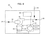
- adapter 22 includes at least one power source 40 electrically connected to pump 38. Any power source capable of providing sufficient power to operate pump 38 and any other electrical or electronic system contained in adapter 22 can be used. Suitable power sources 40 include batteries, fuel cells and solar cells or panels. Power source 40 can be located internal to adapter 22, external to adapter 22 or both. As illustrated in Fig. 8 , power source 40 is a battery contained within adapter 22.
- power source 40 is disposed in at least one of first electronic device 11 and second electronic device 18. If adapter 22 is connected to a fuel container, then power source can be contained within this fuel container.
- power source 40 is a fuel cell or battery, such as fuel cells 13 and 16. As illustrated power source is either first fuel cell 13 or second fuel cell 16.
- At least one of fuel cartridge 12, first electronic device 11, first fuel cell 13, second electronic device 18, fuel chamber 14 and second fuel cell 16 includes a first set of electrical connectors 42
- adapter 22 contains a second set of electrical connectors 44 in contact with the first set of electrical connectors 42.
- first and second sets of electrical connectors 42, 44 can be arranged as a series of metal plates or surfaces that align and come into contact when input and output connectors 24, 26 are brought into contact with fuel cartridge 12 and fuel chamber 14.
- first and second set of electrical connectors 42, 44 can be used to transfer digital signals and telemetry among the various components of filling system 10.
- electric pump 38 can be started and stopped manually using electrical switch 29 located in adapter 22 between power source 40 and pump 38.
- electrical switch 29 is accessible to the user of adapter 22 to turn pump 38 on and off.
- switch 29 is illustrated as a hard-wired electrical switch, switch 29 could alternatively be in communication with logic control unit 46 disposed within adapter 22.
- Logic control unit 46 is connected to pump 38 and any other electronic device located within adapter 22 including electronically controllable valves, lights and displays.
- Logic control unit 46 can also be in communication with logic control units and other electronic systems located in fuel cartridge 12 and electronic device 18.
- First and second sets of electrical connectors 42, 44 can provide communication among these devices.
- Logic control unit 46 can also include the necessary driver and control circuitry for pump 38, or this circuitry can be provided separately. Power is supplied to logic control unit 46 by power source 40. Logic control unit 46 can also be positioned on the fuel cell or on the device that the fuel cell powers, and be in electrical contact with adapter 22 through electrical connectors, such as connectors 42 and 44.
- Suitable logic control units include programmable logic controllers, hard-wired logic controllers and electrically erasable programmable read-only memory (EEPROM). Examples of suitable EEPROMs can be found in co-pending and co-owned U.S. patent application no. 1 O1725,237, entitled “Fuel Cell Supply Including an Information Storage Device and Control System” filed on even date herewith. This application is incorporated herein by reference in its entirety.
- filling device in another embodiment, includes a system for monitoring the amount of fuel in fuel chamber 14 or the amount of fuel that has been transferred from fuel cartridge 12 to fuel chamber 14.
- the fuel monitoring system can automatically halt the transfer of fuel when the level of fuel reaches a predetermined value by stopping pump 38 or closing valve 36.
- Suitable values for the level of fuel include up to about 85% to about 95% of the capacity of fuel chamber 14.
- the fuel monitoring system is preferably arranged to automatically stop the flow of fuel
- the system can also provide a notification to the user that fuel chamber 14 is sufficiently full. The user would then stop the transfer of fuel in response to this indication.
- Notification of the status or operation of adapter 22 can be provided to the user through one or more displays 50 or indicator lights 31 mounted on adapter 22, on the electrical device or on the cartridge to be readily viewable by the user as shown in Figs. 7 and 8 .
- Suitable displays 50 and indicator lights 31 include light emitting diodes and liquid crystal displays.
- Display 50 and indicator lights 31 provide visual indication of the various functions and information regarding filling system 10 including "Power On", “Battery Low”, “Pump On", “Fuel Level” and “Fuel Cartridge Full” among others.
- Display 50 and indicator lights 31 are connected to and controlled by logic control unit 46.
- This fuel monitoring system is connected to adapter 22 and in one embodiment is completely contained within adapter 22. Suitable systems monitor information such as the back pressure from fuel chamber 14 or the cumulative amount of fuel transferred to determine when a sufficient amount of fuel has been transferred to fuel chamber 14.
- the fuel monitoring system includes logic control unit 46.
- the fuel monitoring system includes fuel gauge 48 connected to fuel chamber 14 to measure the amount of remaining fuel in fuel chamber 14. Examples of suitable electronically readably fuel gauges are shown in commonly owned, co-pending U.S. patent application no. 10/725,236 , entitled “Fuel Gauge for Fuel Cartridges" filed on even date herewith. This application is incorporated herein by reference in its entirety. Fuel gauge 48 can be in contact with logic control unit 46 through the first and set sets of electric contacts 42, 44.
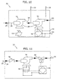
- adapter 22 includes two pumps, first manual pump 52 and second electronic pump 54.
- Electronic pump 54 is connected to logic control unit 46.
- Logic control unit 46 receives power from power source 40 external to adapter 22 and fuel level information through contacts 44.
- power source 40 is second fuel cell 16 inside second electronic device 18. Since fuel chamber 14 may be empty, manual pump 52 is used to transfer fuel to fuel chamber 14 until there is sufficient fuel for fuel cell 16 to provide power to logic control unit 46 and electronic pump 54 via electrical contacts 44. At that point, manual pumping can stop and electronic pump 54 can take over.
- Manual pump 52 and be positioned in series or in parallel with electronic pump 54.
- manual pump 52 can be replaced by solar cells and panels 53 that can convert natural light and artificial light to electricity to power pump 54.
- manual pump 54 can be replaced by other external power sources such as batteries.
- one or more pressure relief valves 33 can be provided in communication with micro-channels 34.
- pump 38 can be combined with various arrangements of valves and other flow controllers to achieve the desired amount of control in the fuel flow transfer.
- pump 38 can be in fluid communication with solenoid valve 39 and check valve 56.
- Pump 38 and solenoid valve 39 are in communication with power supply 40 and logic control unit 46 are necessary to control the operation of adapter 22 and the flow of fuel from fuel cartridge 12 to fuel chamber 14.
- filling system 10 provides a method for in-situ filling of fuel chambers or cartridges disposed within electronic devices that contain fuel cells for providing power the necessary power for the electronic device.
- a spare fuel container or fuel cartridge containing the proper type of fuel for the fuel cell is selected.
- a fuel cartridge is selected that has a substantially larger volume of fuel than the fuel chamber.
- the fuel chamber can be disposed in a cellular telephone, and the fuel cartridge is from a laptop computer.
- the fuel cartridge is then brought into contact and fluid communication with the fuel chamber.
- fluid communication between the cartridge and container is not established until the two components are completely and adequately connected together.
- the fusel cartridge is brought into direct contact with the fuel chamber.
- the fuel cartridge and fuel chamber are brought into contact using a manifold system or an adapter.
- an adapter When an adapter is used, the fuel cartridge is connected to an input of the adapter and the fuel chamber is connected to an output of the adapter.
- the desired amount of fuel is transferred from the fuel supply to the receiving fuel cartridge or fuel chamber.
- the level of fuel in the receiving fuel cartridge chamber is monitored. When the fuel level in the fuel cartridge or chamber reaches a predetermined value, the transfer of fuel is stopped. Typically, the transfer of fuel is stopped when the fuel level reaches about 85% to about 95% of the capacity of the fuel chamber. Monitoring of the fuel level and halting the fuel transfer can be accomplished manually or automatically. Once the chamber has been re-filled to the desired level, the fuel supply and the fuel chamber are disconnected. The connection points are then sealed to prevent leakage. This sealing may take place automatically or manually. The connections points may also be retracted into the cartridge or the electronic device containing the fuel chamber to prevent damage to the connectors.
Abstract
Description
- This invention generally relates to fuel containers for fuel cells, and more particularly this invention relates to refillable fuel cartridges.
- Fuel cells are devices that directly convert chemical energy of reactants, i.e., fuel and oxidant, into direct current (DC) electricity. For an increasing number of applications, fuel cells are more efficient than conventional power generation, such as combustion of fossil fuel and more efficient than portable power storage, such as lithium-ion batteries.
- In general, fuel cell technologies include a variety of different fuel cells, such as alkali fuel cells, polymer electrolyte fuel cells, phosphoric acid fuel cells, molten carbonate fuel cells, solid oxide fuel cells and enzyme fuel cells. Today's more important fuel cells can be divided into three general categories, namely, fuel cells utilizing compressed hydrogen (H2) as fuel; proton exchange membrane (PEM) fuel cells that use methanol (CH3OH), sodium borohydride (NaBH4), hydrocarbons (such as butane) or other fuels reformed into hydrogen fuel; and PEM fuel cells that use methanol (CH3OH) fuel directly ("direct methanol fuel cells" or DMFC). Compressed hydrogen is generally kept under high pressure and is therefore difficult to handle. Furthermore, large storage tanks are typically required and cannot be made sufficiently small for consumer electronic devices. Conventional reformat fuel cells require reformers and other vaporization and auxiliary systems to convert fuels to hydrogen to react with oxidant in the fuel cell. Recent advances make reformer or reformat fuel cells promising for consumer electronic devices. DMFC, where methanol is reacted directly with oxidant in the fuel cell, is the simplest and potentially smallest fuel cell, and also has promising power application for consumer electronic devices.
- DMFC for relatively larger applications typically comprises a fan or compressor to supply an oxidant, typically air or oxygen, to the cathode electrode, a pump to supply a water/methanol mixture to the anode electrode and a membrane electrode assembly (MEA). The MEA typically includes a cathode, a PEM and an anode. During operation, the water/methanol liquid fuel mixture is supplied directly to the anode and the oxidant is supplied to the cathode. The chemical-electrical reaction at each electrode and the overall reaction for a direct methanol fuel cell are described as follows:
- Reaction at the anode:
CH3OH + H2O → CO2 + 6H+ + 6e-
- Reaction at the cathode:
O2 + 4H+ + 4e- → 2 H2O
- The overall fuel cell reaction:
CH3OH + 1.5 O2 - CO2 + 2 H2O
- Due to the migration of the hydrogen ions (H+) through the PEM from the anode through the cathode and due to the inability of the free electrons (e-) to pass through the PEM, the electrons must flow through an external circuit, which produces an electrical current through the external circuit. The external circuit may be any useful consumer electronic devices, such as mobile or cell phones, calculators, personal digital assistants, laptop computers, and power tools, among others. DMFC is discussed in United States patent nos.
5,992,008 and5,945,231 , which are incorporated by reference in their entireties. Generally, the PEM is made from a polymer, such as Nafion® available from DuPont, which is a perfluorinated material having a thickness in the range of about 0.05 mm to about 0.50 mm, or other suitable membranes. The anode is typically made from a Teflonized carbon paper support with a thin layer of catalyst, such as platinum-ruthenium, deposited thereon. The cathode is typically a gas diffusion electrode in which platinum particles are bonded to one side of the membrane. - The cell reaction for a sodium borohydride reformer fuel cell is as follows:
NaBH4 (aqueous) + 2H2O → (heat or catalyst) → 4(H2) + (NaBO2) (aqueous) H2 → 2H+ + 2e- (at the anode)
2(2H+ + 2e-) + O2 → 2H2O (at the cathode)
Suitable catalysts include platinum and ruthenium, among other metals. The hydrogen fuel produced from reforming sodium borohydride is reacted in the fuel cell with an oxidant, such as O2, to create electricity (or a flow of electrons) and water byproduct. Sodium borate (NaBO2) byproduct is also produced by the reforming process. Sodium borohydride fuel cell is discussed in United States published patent application no.2003/0082427 , which is incorporated herein by reference. - One of the important features for fuel cell applications is fuel storage. Another important feature is the regulation of the transport of fuel out of the fuel cartridge to the MEA. To be commercially useful, fuel cells such as DMFC systems should have the capability of storing sufficient fuel to satisfy a consumer's normal usage. For example, for mobile or cell phones, for notebook computers, and for personal digital assistants (PDAs), fuel cells need to power these devices for at least as long as the current batteries, and preferably much longer. Additionally, fuel cells should have easily replaceable or refillable fuel supplies to minimize or obviate the need for lengthy recharges required by the current rechargeable batteries.
- Suitable fuel supplies can be either disposable cartridges or refillable cartridges. For the disposable cartridges, the consumer must carry a sufficient supply of spare fuel cartridges for each electronic device. Absent a correct spare cartridge, fuel cannot be supplied to the fuel cell. In addition, once these fuel cartridges are empty, they cannot be refilled and are simply discarded.
- Refillable fuel cartridges alleviate having to discard empty cartridges. However, it is desirable to be able to refill these fuel cartridges in a simple and efficient manner, and to be able to refill the empty cartridges in-situ without having to remove them from the electronic device. Additionally, it is desirable to provide a system for transferring fuel from the fuel cartridge in one electronic device to the fuel cartridge or to an internal fuel chamber in a second electronic device. Therefore, fuel can be shared among various electronic devices. Suitable fuel filling and transfer systems would be arranged to handle a wide variety of fuel cartridges.
- The present invention is directed to a filling system or filling device for transferring fuel from one fuel supply to another fuel supply, or from a fuel supply directly into an internal chamber or cartridge disposed in the electronic device. The fuel supply can be a stand-alone fuel container, another fuel cartridge or internal fuel chamber disposed within another electronic device, or an unused fuel cartridge.
- In one embodiment, the filling system includes a first fuel chamber arranged to supply fuel to a first fuel cell disposed in a first electronic device through a first fuel connector. The filling system further includes a second electronic device having a second fuel cell and a second fuel chamber. A second fuel connector is attached to the second fuel chamber and is arranged to connect to the first fuel connector to facilitate the transfer of fuel from the first fuel chamber to the second fuel chamber. The fuel connectors are preferably valve connectors, so that the fuel connectors provide a seal to the fuel supply, fuel cartridges or chambers when they are unconnected.
- In another embodiment, the filling device includes an adapter for connecting a fuel supply to a refillable fuel cartridge or a fuel chamber. The adapter includes an input connector to connect the adapter to the fuel supply and an output connector to connect the adapter to the fuel cartridge or chamber. The adapter can be arranged as a passive device for use with pressurized fuel supplies and gravity feed systems, or as an active device using a pump and valve system.
- In an active system, the adapter includes at least one pump in communication with the input and output connectors. The pump is arranged to transfer fuel from the fuel supply to the refillable fuel cartridge or chamber. The pump can be a manual/mechanical pump or electric pump. In addition, the adapter can include one or more valves between the connectors to selectively stop or regulate the flow of fuel from the fuel supply to the fuel cartridge or chamber. In addition to internal valves, both the input and output connectors can be one half of a two-component valve system. The corresponding second halves of the two-component valve system are attached to the fuel supply and fuel refillable cartridge or chamber.
- The filling device also may include the necessary power sources and controllers to control the operation of the adapter and to run the pumps and valves. These power sources and controllers can be located in the first electronic device, the second electronic device or the adapter. All of these components can be in communication with each other through electrical contacts. The filling device can also include a fuel monitoring system to provide for adequate and proper filling of the fuel chamber. The entire system can be arranged to be operated manually or automatically, and the status of the system can be indicated on a display mounted to the adapter, electric device or cartridge.
- In the accompanying drawings, which form a part of the specification and are to be read in conjunction therewith and in which like reference numerals are used to indicate like parts in the various views:
-
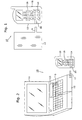
FIG. 1 is a plan view of an embodiment of the filling system in accordance with the present invention; -
FIG. 2 is a perspective view of another embodiment of the filling system; -
FIG. 3 is a schematic representation of an embodiment of a retractable connector in a retracted position for use in the filling system; -
FIG. 4 is a schematic representation of the retractable connector in an extended position; -
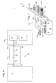
FIG. 5 is a schematic representation of an embodiment of a manifold for use with the filling system; -
FIG. 6 is a schematic representation of another embodiment of the filling system including an adapter; -
FIG. 7 is a plan view of another embodiment of the adapter for use in the filling system; -
FIG. 8 is a schematic representation of another embodiment of the adapter for use in the filling system; -
FIG. 9 is a schematic representation of another embodiment of the filling system; -
FIG. 10 is a schematic representation of another embodiment of an adapter for use in the filling system; and -
FIG. 11 is a schematic representation of yet another embodiment of an adapter for use in the filling system. - The present invention is directed to a system for use in filling or re-filling fuel supplies and can be used with a wide variety of fuel cartridges storing fuel cell fuels including methanol and water, methanol/water mixture, methanol/water mixtures of varying concentrations and pure methanol. These fuel cartridges can also contain other types of fuel cell fuels, for example ethanol, or other chemicals that may improve the performance or efficiency of fuel cells. Suitable fuel cartridges are disclosed and described in co-pending, U.S. patent application entitled "Fuel Cartridge for Fuel Cells," filed on January 31, 2003, bearing serial no.
10/356,793 10/629,004 - The term "fuel" as used herein includes all fuels that can be reacted in fuel cells, and includes all of the above listed suitable fuels, liquids, chemicals and mixtures thereof. The fuel cartridge may contain other types of fuel cell fuels, such as ethanol or other alcohols, chemicals that can be reformatted into hydrogen, or other chemicals that may improve the performance or efficiency of fuel cells. Suitable fuels also include potassium hydroxide (KOH) electrolytic solution, which is usable with metal fuel cells or alkali fuel cells, and can be stored in fuel cartridges. For metal fuel cells, fuel is in the form of fluid borne zinc particles immersed in a KOH electrolytic reaction solution, and the anodes within the cell cavities are particulate anodes formed of the zinc particles. KOH electrolytic solution is disclosed in United States published patent application no.
2003/0077493 , entitled "Method of Using Fuel Cell System Configured to Provide Power to One or More Loads," published on April 24, 2003, which is incorporated herein by reference in its entirety. - Fuels also include a mixture of methanol, hydrogen peroxide and sulfuric acid, which flows past a catalyst formed on silicon chips to create the fuel cell reaction. Additional fuels include the aqueous sodium borohydride (NaBH4) and water discussed above. Fuels further include hydrocarbon fuels, disclosed in United States published patent application no.
2003/0096150 , entitled "Liquid Hereto-Interface Fuel Cell Device," published on May 22, 2003, which is incorporated herein by reference in its entirety. The present invention is, therefore, not limited to any particular arrangement of fuel cartridge or to any particular type of fuels or liquids contained in the cartridge. - Unless otherwise noted, as used herein, the term "fuel supply" includes, but is not limited to cartridge, fuel cartridge, fuel container, fuel tanks, fuel reservoir, fuel refilling tank, fuel chamber including refillable fuel chamber disposed inside the electronic device and other containers that store fuel. "Fuel supply" also includes those with single or multiple internal compartments and further includes those that contain one or more fuels. "Fuel supply" may be large or small and may have multiple fluid connections. The term "cartridge" or "fuel cartridge" include, but are not limited to, cartridge, fuel cartridge, disposable cartridges, refillable/reusable cartridges, cartridges that reside inside an electronic device, cartridges that reside outside of the electronic devices. "Fuel chamber" includes "cartridge" or "fuel cartridge" and any internal chamber including refillable chamber inside a device adapted to store fuel.
- The fuel supply of the present invention can also be used to store fuels that are not used in fuel cells. These applications include, but are not limited to, storing hydrocarbons and hydrogen fuels for micro gas-turbine engine built on silicon chips, discussed in "Here Come the Microengines," published in The Industrial Physicist, (Dec. 2001/Jan. 2002) at pp. 20-25. Other applications include storing traditional fuels for internal combustion engines, and hydrocarbons, such as butane for pocket and utility lighters and liquid propane.
- Referring initially to
Figs. 1 and 2 , the present invention is directed to fillingsystem 10 that includesfirst fuel supply 12 arranged to supply fuel tofirst fuel cell 13 disposed in firstelectronic device 11. Althoughfuel supply 12 is illustrated asfuel cartridge 12 inFig. 2 and is referred hereinafter asfuel cartridge 12, any fuel supply arranged to hold or store fuel cell fuel can be used.First fuel cartridge 12 can be a pressurized or a non-pressurized container. In order to supplyfirst fuel cell 13 with fuel,first fuel cartridge 12 includes firstfuel cartridge connector 9. Firstelectronic device 11 can be any consumer electronic device capable of being arranged to receive power fromfirst fuel cell 13. Examples of suitable consumer electronic devices include, but are not limited to, laptop or handheld computers, cellular phones, personal digital assistants (PDA's), text messaging systems, power tools, portable tape/radio/compact disc players, flashlights, clocks and electronic toys. - Preferably, first
electronic device 11 is selected such thatfirst fuel cartridge 12 has a relatively large capacity, for example a laptop computer in whichfirst fuel cartridge 12 can have a size comparable to conventional laptop batteries. Therefore, electronic devices having relatively large fuel cartridges, for example the laptop computer, can be used to re-fill smaller fuel cartridges, and small cartridges could be emptied into a larger cartridge for transportation, recycling or other environmental reasons.. This arrangement also obviates the need to carry a separate container specifically for holding spare fuel, since the fuel cartridges can be used directly with a fuel cell or as a spare fuel supply.First fuel cartridge 12 can be removed or be fixed within firstelectronic device 11. - Filling
system 10 also includes secondelectronic device 18 arranged to receive power fromsecond fuel cell 16 disposed therein. Suitable secondelectronic devices 18 are the same as for firstelectronic device 11. Secondelectronic device 18 includes internal,re-fillable fuel chamber 14 in fluid communication withsecond fuel cell 16 to deliver fuel thereto. Therefore,fuel cell 16 supplies the necessary power toelectronic device 18 using fuel supplied byfuel chamber 14. Preferably, secondelectronic device 18 is selected such thatinternal fuel chamber 14 has a smaller volume thanfirst fuel cartridge 12. - In one embodiment,
internal fuel chamber 14 is a second fuel cartridge. The second fuel cartridge is re-fillable and can be removed from secondelectronic device 18 or be fixed in place and refilled with a refilling valve exposed to the outside of the electronic device. Typically, empty fuel cartridges are removed from the electronic device and replaced with new fuel cartridges. In accordance with the present invention, the second fuel cartridge is refilled and not discarded. In one embodiment, the second fuel cartridge is removed fromelectronic device 18 and refilled with fuel. Following refilling, the second fuel cartridge is reinserted intoelectronic device 18. - In accordance to another aspect of the present invention,
fuel chamber 14 is refilled in-situ, i.e., refilling without removing from the electronic device. In order to facilitate in-situ refilling,fuel chamber 14 includes fuel chamber connector orre-filling connector 20.Fuel chamber connector 20 extends fromfuel chamber 14, can be arranged as either a female connector or a male connector and is arranged to be accessible throughelectronic device 18. This access can be provided through a hole or port inelectronic device 18 that exposes refillingconnection 20. Preferably,fuel chamber connector 20 is arranged to be flush withexterior surface 15 of secondelectronic device 18. In one embodiment as shown inFig. 1 ,fuel chamber connector 20 is arranged to connect to firstfuel cartridge connector 9 to facilitate the transfer of fuel fromfirst fuel cartridge 12 tofuel chamber 14 in-situ. In this embodiment,first fuel cartridge 12 is removed from firstelectronic device 11 before being connected to secondelectronic device 18. Therefore, firstfuel cartridge connector 9 is used as a fuel supply tofirst fuel cell 13 and to re-fillfuel chamber 14. - Generally,
fuel cartridge 12 can be a fuel supply adapted to power electronic devices and to refill other fuel cartridges and fuel chambers, or adapted only to refill fuel cartridges and chambers. Additionally, one or more smaller fuel supplies can be used to refill a larger fuel cartridge or chamber. - As illustrated, first
fuel cartridge connector 9 is a male connector, andfuel chamber connector 20 is a female connector. Fuel flow is either by gravity or under pressure fromfirst fuel cartridge 12 tointernal fuel chamber 14. Pressure can be supplied by hand squeezing the first cartridge, when the outer casing of the cartridge is relatively flexible. To prevent undesired leakage of fuel from eitherfirst fuel cartridge 12 orinternal fuel chamber 14, before firstfuel cartridge connector 9 andfuel chamber connector 20 are brought into proper contact, check valves, manual or spring-loaded closures, or other seals can be provided in both firstfuel cartridge connector 9 andfuel chamber connector 20. Therefore, fuel flow fromfirst fuel cartridge 12 tointernal fuel chamber 14 is not established until firstfuel cartridge connector 9 is brought into contact withfuel chamber connector 20. Such valves, valve components, seals and closures are disclosed in co-pending, commonly owned U.S. patent application entitled "Fuel Cartridge with Connecting Valve," filed on July 29, 2003, bearing serial no.10/629,006 - As shown in
Fig. 2 , in another embodiment,first fuel cartridge 12 can be used to re-fillinternal chamber 14 without removingfirst fuel cartridge 12 from firstelectronic device 11. In this embodiment,first fuel cartridge 12 further includessecond connector 17. As with firstfuel cartridge connector 9,second connector 17 is arranged to connect tofuel chamber connector 20 and can be either a male connector or a female connector. - It is desirable from the standpoint of both functionality and aesthetics not to have connectors protruding from either
first fuel cartridge 12 or secondelectronic device 18. In one embodiment, firstfuel cartridge connector 9,second connector 17 orfuel chamber connector 20 can be arranged asretractable connector 30. As illustrated inFigs. 3 and 4 forsecond connector 17,retractable connector 30 is in a retracted position such that it is flush withedge 32 offuel cartridge 12. By rotatingretractable connector 30 in the direction of arrow A,retractable connector 30 is moved to an extended position as shown inFig. 4 .Retractable connector 30 can also be constructed so that its internal passage is open in the extended position and closed in the retracted position, providing a seal or acting like a valve forsecond connector 17. Although illustrated as a rotating structure,retractable connector 30 can be any structure that provides for retraction to a position flush withedge 32 including sliding, folding and telescoping structures. - First
fuel cartridge connector 9,second connector 17 andfuel chamber connector 20 can be arranged as mating, two-component valve systems, as disclosed in the '006 application. Each valve component is capable of providing a seal. In one embodiment, firstfuel cartridge connector 9 orsecond connector 17 is one half of a two-component valve, andfuel chamber connector 20 is the complementary half of the two-component valve. In addition to providing for connectivity and fluid communication betweenfirst fuel cartridge 12 andinternal chamber 14, these valve halves sealfirst fuel cartridge 12 andinternal fuel chamber 14 when not connected together. Suitable two-component valves are fully disclosed in the '006 patent application, discussed above. These two-component valves can be uniquely arranged so that only specific halves fit together. This uniqueness can be used to provide a method to ensure that the proper fuel cartridges are matched to the internal fuel containers. Alternatively, the valve halves can be universal, mix-and-match type fittings. -
First fuel cartridge 12 can be used to re-fill more than one cartridge orinternal fuel chamber 14. Preferably,first fuel cartridge 12 can be used to simultaneously fill a plurality of cartridges orinternal fuel chambers 14 disposed in a plurality of secondelectronic devices 18. As illustrated inFig. 5 ,manifold 19 is provided to connectfirst fuel cartridge 12 to the plurality ofinternal chambers 14.Manifold 19 includes at least onemanifold input 21 arranged to connect to firstfuel cartridge connector 9 orsecond connector 17 and a plurality ofmanifold outputs 23 arranged to connect to one of the plurality offuel chamber connectors 20. Suitable connections formanifold input 21 andmanifold outputs 23 are the same as for firstfuel cartridge connector 9,second connector 17 andfuel chamber connector 20, discussed above. In general, any type of connection capable of providing a sufficient attachment and seal betweenfirst fuel cartridge 12,manifold 19 andfuel chambers 14 can be used including press fit connections, threaded connections, union fittings and the like. In one example,first fuel cartridges 12 is a relatively large fuel supply which is connected tomanifold input 21, and a plurality of electronic devices are connected tomanifold outputs 23 to be refilled or the fuel supply has multiple valves which can be connected to multiple devices. - The inputs and outputs of
manifold 19 are connected together using any suitable fixtures including micro-channel type tubing. These fixtures can be flexible type fittings or rigid fittings. In order to control the flow throughmanifold 19 to and amongfuel chambers 14,manifold 19 includes at least one and preferably a plurality ofvalves 25. These valves can provide simple on and off functionality or can control or limit the flow of fuel. Suitable valves include ball valves, needle valves, three-way and four-way valves, gate valves, butterfly valves, rotary valves and check valves. - Referring
Fig. 6 , in oneembodiment filling system 10 includesadapter 22 that provides an interface betweenfuel cartridge 12 andfuel chamber 14, and facilitates the transfer of fuel fromfuel cartridge 12 tofuel chamber 14.Adapter 22 includes at least oneinput connector 24 to connectadapter 22 tofuel cartridge 12, and at least oneoutput connector 26 to connectadapter 22 tofuel chamber 14.Input connector 24 is in fluid communication withoutput connector 26 throughadapter 22. Various arrangements forinput connector 24 andoutput connector 26 are possible and these connectors can either be the same type of connector or different types of connectors. Any type of connection capable of providing a sufficient attachment and seal with eitherfuel cartridge 12 orfuel chamber 14 can be used including press fit connections, threaded connections, union fittings and the like. Valve components disclosed in the '006 patent application are also usable in this embodiment. - In one embodiment, input and
output connectors output connectors output connectors output connectors 26 can be disposed on a rotatable orslideable rack 27 as illustrated inFig. 7 .Slideable rack 27 is then moved back and forth in the direction of arrow B until desiredoutput connector 26 is in fluid alignment withinput connector 24. Similar selectivity among a plurality of inputs and outputs can also be provided using a plurality of valves internal toadapter 22. - Input and
output connectors input connector 24 andoutput connector 26 are male connectors that engage complimentary female connectors infirst fuel cartridge 12 andfuel chamber 14 respectively. As with firstfuel cartridge connector 9,second connector 17 andfuel chamber connector 20, these male connectors can be arranged as retractable connections. This embodiment eliminates extensions or protrusions fromadapter 22 that can undesirably snag clothing or furniture. Additionally, a separate valve connector, which includes male and/or female connectors having different sizes, may be provided as an intermediate member to connect input connectors to output connectors. - In another embodiment,
input connector 24 is one half of a two-component valve, andfuel cartridge 12 contains the other mating half of the two-component valve. In addition to providing for connectivity and fluid communication betweenfuel cartridge 12 andadapter 22, these valve halves sealfuel cartridge 12 andadapter 22 when not connected together. Suitable two-component valves are fully disclosed in the '006 patent application, discussed above. In addition to this first two-component valve betweenfuel cartridge 12 andadapter 22, a second similar two-component valve can be placed betweenadapter 22 andfuel chamber 14.Output connector 26 is one half of the two-component valve, andconnector 20 offuel chamber 14 is the other complimentary half of the two-component valve. These valve halves can be connected toadapter 22,fuel container 14 andfuel cartridge 12 by any suitable method including press-fitting, pipe threads, adhesives and welds. In one embodiment, these two-component valves are uniquely arranged so that only specific halves fit together. This embodiment can be used to provide a method to ensure that the proper fuel containers are matched to the proper fuel cartridges. Alternatively, the valves halves are universal, mix-and-match type fittings. -
Adapter 22 can be a passive device or an active device. In one embodiment,adapter 22 is arranged as a passive device. This arrangement is suitable when used with pressurized fuel containers or when gravity feed is the preferred method of transferring fuel to fuelchamber 14. Whenadapter 22 is passive,input connector 24 andoutput connector 26 are in direct fluid connection through micro-channel sized piping 34 (Fig. 6 ) that passes throughadapter 22. In order to provide for the ability to control or stop the flow of fuel throughadapter 22,adapter 22 can include one ormore valves 36 disposed betweeninput connector 24 andoutput connector 26.Valves 36 can be arranged to simply provide an on-off function or can be arranged to restrict and control the flow and pressure of fluid throughadapter 22. Suitable valves include ball valves, needle valves, three-way and four-way valves, gate valves, butterfly valves, rotary valves and check valves. In addition,valves 36 can be used alone or in combination with the two-component valves in the input and output connectors. In one embodiment, internalfuel chamber connector 20 includescheck valve 37 to prevent the back-flow of fuel frominternal chamber 14 whenchamber connector 20 is disengaged fromadapter 22. Internalfuel chamber connector 20 or other valves, valve components or other connectors may also include a filler material to control the flow of fuel. Such filler materials are disclosed in the co-pending '793 application. - As is illustrated in
Fig. 8 ,adapter 22 can be arranged as an active device and can include one ormore pumps 38 disposed in piping 34 and in communication with input andoutput connectors fuel cartridge 12 tofuel chamber 14. Preferably, pump 38 is adapted for use with liquid flow rates and is available in small sizes.Pump 38 can be a manual pump or an electronic pump. Suitable manual pumps include blister or bladder type pumps that can be activated by hand pressure, and other manual hand pumps. - In one embodiment, pump 38 is an electric or electronic pump. Preferably, pump 38 has a minimal number of moving parts to minimize breakage. Suitable pumps include microelectromechanical systems (MEMS) pumps, such as those used to pump ink in inkjet printers, to meter drugs in drug delivery systems or to cool micro integrated circuit chips. In particular, suitable MEMS pumps include field-induced flow pumps and membrane-displacement pumps. Field induced pumps utilize an electric or magnetic field to produce fluid flow.
- A suitable field-induced pump is an electro-osmotic pump. Electro-osmotic pumps contain no moving parts and are capable of moving fluids through tight spaces. Electro-osmotic pumps advantageously can move fluid with low conductivity. An electro-osmotic flow is created when a DC potential is applied across a porous media. The liquid in the porous media is driven from the anode or positive electrode to the cathode or negative electrode, when exposed to the DC electrical field. Electro-osmotic pumps are particularly useful in micro-channels, such as those within
adapter 22. Electro-osmotic flow is discussed in detail inU.S. patent no. 3,923,426 entitled, "Electroosmotic Pump and Fluid Dispenser Including Same," issued on December 2, 1975, in "Electroosmotic flow pumps with polymer frits" by S. Zeng, C. Chen, J. Santiago, J. Chen, R. Zare, J. Tripp, F. Svec and J. Frechet, published in Sensors and Actuators B Chemical Journal, vol. 82, pp. 209-212 (2002), and in "A Large Flowrate Electroosmotic Pump with Micron Pores," by S. Yao, D. Huber, J. Mikkelsen and J. Santiago, proceedings of IMECE, 2001 ASME International Mechanical Engineering Congress and Exposition, November 11-16, 2001, New York, NY, among other references. These references are incorporated by reference herein in their entireties. - Other suitable field-induced pumps include, but are not limited to, electrohydrodynamic pumps and magnetohydrodynamic pumps. Membrane-displacement pumps utilize a force, e.g., an electrical charge, applied to a membrane, causing the membrane to move or vibrate to propel the fluid. Suitable membrane-displacement pumps include, but are not limited to piezoelectric pumps, electrostatic pumps and thermopneumatic pumps.
- Suitable piezoelectric pumps usable in
adapter 22 include those available from PAR Technologies, LLC of Newport News, VA. Piezoelectric pumps have no moving parts and are lightweight, compact, rugged, quiet and efficient. These pumps have excitation voltages of greater than about 50 V and current draw, for example from as low as about 15 milliamps up to about 130 milliamps at an input voltage from about 2.2 VDC up to about 12 VDC. The flow rate for piezoelectric pumps is from about 10 ml/hour up to about 900 ml/hour at pressures in the range of about 0 to about 5 psi. The size of the pump is from about 0.5 inch2 up to about 1.5 inch2 by less than about 0.5 inches thick. The piezoelectric pump is constructed from materials that are compatible with the fuels to be used with fuel cells and fuel cartridges. These pumps also operate in a wide range and have long cycle life. - In order to provide the necessary power to drive
pump 38,adapter 22 includes at least onepower source 40 electrically connected to pump 38. Any power source capable of providing sufficient power to operatepump 38 and any other electrical or electronic system contained inadapter 22 can be used.Suitable power sources 40 include batteries, fuel cells and solar cells or panels.Power source 40 can be located internal toadapter 22, external toadapter 22 or both. As illustrated inFig. 8 ,power source 40 is a battery contained withinadapter 22. - In one embodiment as shown in
Fig. 9 ,power source 40 is disposed in at least one of firstelectronic device 11 and secondelectronic device 18. Ifadapter 22 is connected to a fuel container, then power source can be contained within this fuel container. Preferably, when contained in firstelectronic device 11,electronic device 18 or a fuel container,power source 40 is a fuel cell or battery, such asfuel cells first fuel cell 13 orsecond fuel cell 16. - When
power source 40 is located external toadapter 22, electrical connectors are needed to connect the power leads from the external power source to the necessary components withinadapter 22. In one embodiment, at least one offuel cartridge 12, firstelectronic device 11,first fuel cell 13, secondelectronic device 18,fuel chamber 14 andsecond fuel cell 16 includes a first set ofelectrical connectors 42, andadapter 22 contains a second set ofelectrical connectors 44 in contact with the first set ofelectrical connectors 42. These electrical connectors provide sufficient electrical connectivity among the various components of fillingsystem 10 and supply power frompower supply 40 toadapter 22. Any type of electrical connector known and available in the art can be used. For example, first and second sets ofelectrical connectors output connectors fuel cartridge 12 andfuel chamber 14. In addition to supplying electric power, first and second set ofelectrical connectors system 10. - In one embodiment as shown in
Fig. 8 ,electric pump 38 can be started and stopped manually usingelectrical switch 29 located inadapter 22 betweenpower source 40 andpump 38. As shown inFig. 7 ,electrical switch 29 is accessible to the user ofadapter 22 to turnpump 38 on and off. Althoughswitch 29 is illustrated as a hard-wired electrical switch, switch 29 could alternatively be in communication withlogic control unit 46 disposed withinadapter 22.Logic control unit 46 is connected to pump 38 and any other electronic device located withinadapter 22 including electronically controllable valves, lights and displays.Logic control unit 46 can also be in communication with logic control units and other electronic systems located infuel cartridge 12 andelectronic device 18. First and second sets ofelectrical connectors Logic control unit 46 can also include the necessary driver and control circuitry forpump 38, or this circuitry can be provided separately. Power is supplied tologic control unit 46 bypower source 40.Logic control unit 46 can also be positioned on the fuel cell or on the device that the fuel cell powers, and be in electrical contact withadapter 22 through electrical connectors, such asconnectors - Suitable logic control units include programmable logic controllers, hard-wired logic controllers and electrically erasable programmable read-only memory (EEPROM). Examples of suitable EEPROMs can be found in co-pending and co-owned U.S. patent application no. 1 O1725,237, entitled "Fuel Cell Supply Including an Information Storage Device and Control System" filed on even date herewith. This application is incorporated herein by reference in its entirety.
- In another embodiment of filling
device 10 in accordance with the present invention, filling device includes a system for monitoring the amount of fuel infuel chamber 14 or the amount of fuel that has been transferred fromfuel cartridge 12 tofuel chamber 14. The fuel monitoring system can automatically halt the transfer of fuel when the level of fuel reaches a predetermined value by stoppingpump 38 or closingvalve 36. Suitable values for the level of fuel include up to about 85% to about 95% of the capacity offuel chamber 14. - Although the fuel monitoring system is preferably arranged to automatically stop the flow of fuel, the system can also provide a notification to the user that
fuel chamber 14 is sufficiently full. The user would then stop the transfer of fuel in response to this indication. Notification of the status or operation ofadapter 22 can be provided to the user through one ormore displays 50 orindicator lights 31 mounted onadapter 22, on the electrical device or on the cartridge to be readily viewable by the user as shown inFigs. 7 and8 .Suitable displays 50 andindicator lights 31 include light emitting diodes and liquid crystal displays.Display 50 andindicator lights 31 provide visual indication of the various functions and information regarding fillingsystem 10 including "Power On", "Battery Low", "Pump On", "Fuel Level" and "Fuel Cartridge Full" among others.Display 50 andindicator lights 31 are connected to and controlled bylogic control unit 46. - This fuel monitoring system is connected to
adapter 22 and in one embodiment is completely contained withinadapter 22. Suitable systems monitor information such as the back pressure fromfuel chamber 14 or the cumulative amount of fuel transferred to determine when a sufficient amount of fuel has been transferred tofuel chamber 14. In this embodiment, the fuel monitoring system includeslogic control unit 46. In another embodiment as illustrated inFig. 9 , the fuel monitoring system includesfuel gauge 48 connected to fuelchamber 14 to measure the amount of remaining fuel infuel chamber 14. Examples of suitable electronically readably fuel gauges are shown in commonly owned, co-pendingU.S. patent application no. 10/725,236 , entitled "Fuel Gauge for Fuel Cartridges" filed on even date herewith. This application is incorporated herein by reference in its entirety.Fuel gauge 48 can be in contact withlogic control unit 46 through the first and set sets ofelectric contacts - Other embodiments of pumps and valves in
adapter 22 in accordance with the present invention are illustrated inFigs. 10 and 11 . As shown inFig. 10 ,adapter 22 includes two pumps, firstmanual pump 52 and secondelectronic pump 54.Electronic pump 54 is connected tologic control unit 46.Logic control unit 46 receives power frompower source 40 external toadapter 22 and fuel level information throughcontacts 44. Preferably,power source 40 issecond fuel cell 16 inside secondelectronic device 18. Sincefuel chamber 14 may be empty,manual pump 52 is used to transfer fuel to fuelchamber 14 until there is sufficient fuel forfuel cell 16 to provide power tologic control unit 46 andelectronic pump 54 viaelectrical contacts 44. At that point, manual pumping can stop andelectronic pump 54 can take over.Manual pump 52 and be positioned in series or in parallel withelectronic pump 54. Alternatively,manual pump 52 can be replaced by solar cells andpanels 53 that can convert natural light and artificial light to electricity topower pump 54. Additionally,manual pump 54 can be replaced by other external power sources such as batteries. To prevent damage to any of the components of fillingsystem 10 that could result from obstructions inmicro-channels 34 and from attempted overfilling offuel chamber 14, one or morepressure relief valves 33 can be provided in communication withmicro-channels 34. - In the embodiment illustrated in
Fig. 11 , pump 38 can be combined with various arrangements of valves and other flow controllers to achieve the desired amount of control in the fuel flow transfer. For example, pump 38 can be in fluid communication withsolenoid valve 39 andcheck valve 56.Pump 38 andsolenoid valve 39 are in communication withpower supply 40 andlogic control unit 46 are necessary to control the operation ofadapter 22 and the flow of fuel fromfuel cartridge 12 tofuel chamber 14. - In operation, filling
system 10 provides a method for in-situ filling of fuel chambers or cartridges disposed within electronic devices that contain fuel cells for providing power the necessary power for the electronic device. In order to re-fill the fuel chamber within the electronic device, a spare fuel container or fuel cartridge containing the proper type of fuel for the fuel cell is selected. Preferably, a fuel cartridge is selected that has a substantially larger volume of fuel than the fuel chamber. For example, the fuel chamber can be disposed in a cellular telephone, and the fuel cartridge is from a laptop computer. The fuel cartridge is then brought into contact and fluid communication with the fuel chamber. Preferably, fluid communication between the cartridge and container is not established until the two components are completely and adequately connected together. In one embodiment, the fusel cartridge is brought into direct contact with the fuel chamber. In another embodiment, the fuel cartridge and fuel chamber are brought into contact using a manifold system or an adapter. When an adapter is used, the fuel cartridge is connected to an input of the adapter and the fuel chamber is connected to an output of the adapter. - Once the fuel supply is brought into contact with the fuel cartridge or fuel chamber, the desired amount of fuel is transferred from the fuel supply to the receiving fuel cartridge or fuel chamber. In order to control the amount of fuel transferred to the fuel chamber, the level of fuel in the receiving fuel cartridge chamber is monitored. When the fuel level in the fuel cartridge or chamber reaches a predetermined value, the transfer of fuel is stopped. Typically, the transfer of fuel is stopped when the fuel level reaches about 85% to about 95% of the capacity of the fuel chamber. Monitoring of the fuel level and halting the fuel transfer can be accomplished manually or automatically. Once the chamber has been re-filled to the desired level, the fuel supply and the fuel chamber are disconnected. The connection points are then sealed to prevent leakage. This sealing may take place automatically or manually. The connections points may also be retracted into the cartridge or the electronic device containing the fuel chamber to prevent damage to the connectors.
- While it is apparent that the illustrative embodiments of the invention disclosed herein fulfill the objectives of the present invention, it is appreciated that numerous modifications and other embodiments may be devised by those skilled in the art. Additionally, feature(s) and/or element(s) from any embodiment may be used singly or in combination with other embodiment(s). Therefore, it will be understood that the appended claims are intended to cover all such modifications and embodiments, which would come within the spirit and scope of the present invention.
Claims (30)
- An adapter for connecting a first fuel supply to a second fuel supply comprising: an input connector to connect the adapter to the first fuel supply; and an output connector to connect the adapter to the second fuel supply; and wherein the adapter is arranged to transfer fuel from the first fuel supply to the second fuel supply.
- The adapter of claim 1, wherein the adapter further comprises a pump.
- The adapter of claim 2, wherein the pump is a manual pump.
- The adapter of claim 2, wherein the pump is an electric pump.
- The adapter of claim 4, wherein the adapter further comprises a power source to supply power to the electric pump.
- The adapter of claim 5, wherein the power source comprises a battery.
- The adapter of claim 5, wherein the power source comprises a solar panel.
- The adapter of claim 5, wherein the power source comprises a fuel cell.
- The adapter of claim 1, wherein a power source disposed in at least one of the fuel supplies and is adapted to supply power to an electric pump disposed in the adapter and adapted to transfer fuel from the first fuel supply to the second fuel supply.
- The adapter of claim 9, wherein said at least one of the fuel supplies comprises a first set of electrical connectors and the adapter contains a second set of electrical connectors in contact with the first set of electrical connectors to supply power from the power source to the adapter.
- The adapter of claim 5, wherein the adapter further comprises an electrical switch in communication with the pump.
- The adapter of claim 1 further comprising at least one valve arranged to selectively stop the flow of fuel from the first fuel supply to the second fuel supply.
- The adapter of claim 1, wherein the first fuel supply comprises a first half of a twocomponent valve and the input connector comprises a second half of the two-component valve.
- The adapter of claim 1, wherein the second fuel supply is disposed in an electronic device and the adapter transfers fuel to the second fuel supply in-situ.
- The adapter of claim 14, wherein the electronic device comprises a retractable valve connector connectable to the output connector on the adapter.
- The adapter of claim 1, wherein one of the fuel supplies comprises a system for monitoring the amount of fuel contained therein and the adapter is in communication with the fuel monitoring system.
- The adapter of claim 16, wherein said one of the fuel supplies comprises a first set of electrical connectors in contact with the fuel monitoring system and the adapter contains a second set of electrical connectors in contact with the first set of electrical connectors to receive information from the fuel monitoring system.
- The adapter of claim 1 further comprises a display.
- The adapter of claim 18, wherein the display comprises a light emitting diode or a liquid crystal display.
- The adapter of claim 1, wherein the adapter comprises a logic control unit controlling the operation of the adapter.
- The adapter of claim 1, wherein the adapter further comprises a system to monitor a level of fuel within the second fuel supply and the monitoring system stops the flow of fuel from the first fuel supply when the level in the second fuel supply reaches a predetermined level.
- The adapter of claim 21, wherein the second fuel supply comprises a fuel gauge to measure the amount of fuel in the second fuel supply and the monitoring system is in communication with the fuel gauge.
- The adapter of claim 21, wherein the monitoring system comprises a logic control unit to control operation of the adapter.
- The adapter of claim 21, wherein the predetermined value is less than about 85% to about 95% of fuel chamber capacity.
- A method for in-situ filling a fuel chamber disposed within an electronic device that contains a fuel cell for providing power, the method comprising: selecting a fuel supply containing fuel for the fuel cell;
bringing the fuel supply into fluid communication with the fuel chamber; wherein the step of bringing the fuel supply into fluid communication with the fuel chamber comprises bringing a fuel supply connector in fluid communication with a fuel chamber connector, and transferring the fuel from the fuel supply to the fuel chamber. - The method of claim 25 further comprising the step of monitoring the level of fuel in the fuel chamber.
- The method of claim 26 further comprising the step of stopping the transfer of fuel when the fuel level in the fuel chamber reaches a predetermined value.
- The method of claim , wherein the transfer of fuel is stopped when the fuel level reaches about 85% to about 95% of the capacity of the fuel chamber.
- The method of claim 37, wherein the step of bringing the fuel supply into fluid communication with the fuel chamber further comprises the step of providing an adapter between the fuel supply connector and the fuel chamber connector.
- The method of claim 41, wherein the adapter monitors the level of fuel in the fuel chamber; and stops the transfer of fuel when the fuel level in the fuel chamber reaches a predetermined value.
Priority Applications (1)
| Application Number | Priority Date | Filing Date | Title |
|---|---|---|---|
| EP10167699.7A EP2236423B1 (en) | 2003-12-01 | 2004-11-24 | Method and apparatus for filling a fuel container |
Applications Claiming Priority (4)
| Application Number | Priority Date | Filing Date | Title |
|---|---|---|---|
| US10/725,264 US7156131B2 (en) | 2003-12-01 | 2003-12-01 | Method and apparatus for filling a fuel container |
| PCT/US2004/039242 WO2005055339A2 (en) | 2003-12-01 | 2004-11-24 | Method and apparatus for filling a fuel containers |
| EP04816975A EP1699700A4 (en) | 2003-12-01 | 2004-11-24 | Method and apparatus for filling a fuel container |
| EP10167699.7A EP2236423B1 (en) | 2003-12-01 | 2004-11-24 | Method and apparatus for filling a fuel container |
Related Parent Applications (2)
| Application Number | Title | Priority Date | Filing Date |
|---|---|---|---|
| EP04816975.9 Division | 2004-11-24 | ||
| EP04816975A Division EP1699700A4 (en) | 2003-12-01 | 2004-11-24 | Method and apparatus for filling a fuel container |
Publications (3)
| Publication Number | Publication Date |
|---|---|
| EP2236423A2 true EP2236423A2 (en) | 2010-10-06 |
| EP2236423A3 EP2236423A3 (en) | 2011-03-02 |
| EP2236423B1 EP2236423B1 (en) | 2018-09-26 |
Family
ID=34620272
Family Applications (2)
| Application Number | Title | Priority Date | Filing Date |
|---|---|---|---|
| EP10167699.7A Not-in-force EP2236423B1 (en) | 2003-12-01 | 2004-11-24 | Method and apparatus for filling a fuel container |
| EP04816975A Withdrawn EP1699700A4 (en) | 2003-12-01 | 2004-11-24 | Method and apparatus for filling a fuel container |
Family Applications After (1)
| Application Number | Title | Priority Date | Filing Date |
|---|---|---|---|
| EP04816975A Withdrawn EP1699700A4 (en) | 2003-12-01 | 2004-11-24 | Method and apparatus for filling a fuel container |
Country Status (14)
| Country | Link |
|---|---|
| US (2) | US7156131B2 (en) |
| EP (2) | EP2236423B1 (en) |
| JP (1) | JP2007513482A (en) |
| KR (1) | KR101155850B1 (en) |
| CN (2) | CN102616720B (en) |
| AR (1) | AR046730A1 (en) |
| AU (1) | AU2004296033A1 (en) |
| BR (1) | BRPI0416465A (en) |
| CA (1) | CA2544408C (en) |
| MY (1) | MY145019A (en) |
| RU (1) | RU2360331C2 (en) |
| TW (1) | TWI298558B (en) |
| WO (1) | WO2005055339A2 (en) |
| ZA (1) | ZA200604457B (en) |
Cited By (2)
| Publication number | Priority date | Publication date | Assignee | Title |
|---|---|---|---|---|
| EP2441681A3 (en) * | 2005-02-16 | 2012-05-02 | Société BIC | Fuel supply systems having operational resistance |
| US8613297B2 (en) | 2003-07-29 | 2013-12-24 | Societe Bic | Fuel supply systems having operational resistance |
Families Citing this family (38)
| Publication number | Priority date | Publication date | Assignee | Title |
|---|---|---|---|---|
| US20050008908A1 (en) * | 2003-06-27 | 2005-01-13 | Ultracell Corporation | Portable fuel cartridge for fuel cells |
| US20060127711A1 (en) * | 2004-06-25 | 2006-06-15 | Ultracell Corporation, A California Corporation | Systems and methods for fuel cartridge distribution |
| US20050106441A1 (en) * | 2003-09-30 | 2005-05-19 | Canon Kabushiki Kaisha | Hydrogen cartridge, fuel cell system and method of attaching hydrogen cartridge |
| US7156131B2 (en) * | 2003-12-01 | 2007-01-02 | Societe Bic | Method and apparatus for filling a fuel container |
| US7655331B2 (en) | 2003-12-01 | 2010-02-02 | Societe Bic | Fuel cell supply including information storage device and control system |
| US20050162122A1 (en) * | 2004-01-22 | 2005-07-28 | Dunn Glenn M. | Fuel cell power and management system, and technique for controlling and/or operating same |
| US7117906B2 (en) | 2004-02-06 | 2006-10-10 | Societe Bic | Datum based interchangeable fuel cell cartridges |
| US7968250B2 (en) * | 2004-06-25 | 2011-06-28 | Ultracell Corporation | Fuel cartridge connectivity |
| US7648792B2 (en) * | 2004-06-25 | 2010-01-19 | Ultracell Corporation | Disposable component on a fuel cartridge and for use with a portable fuel cell system |
| JP5855328B2 (en) | 2005-07-18 | 2016-02-09 | インテリジェント エナジー リミテッドIntelligent Energy Limited | Separable fuel cartridge |
| JP4632910B2 (en) * | 2005-09-15 | 2011-02-16 | Necパーソナルプロダクツ株式会社 | Fuel supply system and fuel supply method |
| US7992599B2 (en) * | 2005-09-23 | 2011-08-09 | Angstrom Power Incorporated | Refueling station |
| JP4911562B2 (en) * | 2005-09-30 | 2012-04-04 | 三洋電機株式会社 | Fuel cell system |
| JP5068657B2 (en) * | 2005-09-30 | 2012-11-07 | 京セラ株式会社 | FUEL CELL AND ELECTRONIC DEVICE HAVING THE FUEL CELL |
| JP4835222B2 (en) * | 2006-03-24 | 2011-12-14 | 株式会社デンソー | Vehicle power generation system |
| TW200806392A (en) | 2006-06-20 | 2008-02-01 | Lynntech Inc | Microcartridge hydrogen generator |
| US8235077B2 (en) * | 2006-09-14 | 2012-08-07 | Societe Bic | Device for refilling a fuel cartridge for a fuel cell |
| JP2008078076A (en) * | 2006-09-25 | 2008-04-03 | Suzuki Motor Corp | Fuel supply device of fuel cell system |
| US8822888B2 (en) * | 2006-11-16 | 2014-09-02 | Societe Bic | Fuel cartridge for fuel cells |
| US20080157918A1 (en) * | 2006-12-29 | 2008-07-03 | Motorola, Inc. | System for validating refillable fuel cartridges |
| JP5025288B2 (en) * | 2007-03-05 | 2012-09-12 | 株式会社東芝 | Fuel cell system and electronic device |
| TW200905964A (en) * | 2007-07-23 | 2009-02-01 | Coretronic Corp | Fuel cell system |
| JP2009070594A (en) * | 2007-09-11 | 2009-04-02 | Panasonic Corp | Fuel supply adapter device and fuel supply device |
| JP2009104873A (en) * | 2007-10-23 | 2009-05-14 | Panasonic Corp | Fuel supply device |
| JP2009117268A (en) * | 2007-11-09 | 2009-05-28 | Panasonic Corp | Fuel supply system |
| DE102008023945A1 (en) | 2008-05-16 | 2009-11-19 | Evgueni, Levotmann | Converting heat into electrical energy during the continuous application of heat on working fluid, which occurs from the electrochemical reaction in the fuel cell using water-soluble electrolytes and bromine as oxygen carrier |
| JP2009277560A (en) * | 2008-05-16 | 2009-11-26 | Sony Corp | Fuel cartridge and fuel cell system |
| JP2009301961A (en) * | 2008-06-16 | 2009-12-24 | Sony Corp | Fuel filling kit and fuel filling method |
| US8703358B2 (en) * | 2008-11-20 | 2014-04-22 | Mti Microfuel Cells, Inc. | Fuel cell feed systems |
| US8019839B2 (en) | 2009-05-11 | 2011-09-13 | Accenture Global Services Limited | Enhanced network adapter framework |
| US9112199B2 (en) * | 2011-02-04 | 2015-08-18 | Raytheon Company | Fuel cell system and method |
| JP2012189498A (en) * | 2011-03-11 | 2012-10-04 | Sharp Corp | Electric field generation device and electric field generation method |
| WO2012129266A1 (en) | 2011-03-22 | 2012-09-27 | Raytheon Company | Systems and methods providing a wearable power generator |
| EP2756740B1 (en) * | 2011-09-15 | 2018-04-11 | Cold Plasma Medical Technologies, Inc. | Cold plasma treatment devices and associated methods |
| KR101500629B1 (en) * | 2013-11-15 | 2015-03-09 | 주식회사 경동나비엔 | Device for fire pressure reduction in oil burner using orifice |
| CN103811784A (en) * | 2014-02-19 | 2014-05-21 | 四川上恩科技发展有限公司 | Hydrogen inlet device for fuel cell |
| GB2531303B (en) | 2014-10-15 | 2019-12-25 | Intelligent Energy Ltd | A gas connector |
| CA3138041A1 (en) * | 2019-04-30 | 2020-11-05 | B & T Products Ltd. | A fuel container |
Citations (6)
| Publication number | Priority date | Publication date | Assignee | Title |
|---|---|---|---|---|
| US3923426A (en) | 1974-08-15 | 1975-12-02 | Alza Corp | Electroosmotic pump and fluid dispenser including same |
| US5945231A (en) | 1996-03-26 | 1999-08-31 | California Institute Of Technology | Direct liquid-feed fuel cell with membrane electrolyte and manufacturing thereof |
| US5992008A (en) | 1998-02-10 | 1999-11-30 | California Institute Of Technology | Direct methanol feed fuel cell with reduced catalyst loading |
| US20030077493A1 (en) | 2001-08-15 | 2003-04-24 | Colborn Jeffrey A. | Methods of using fuel cell system configured to provide power to one or more loads |
| US20030082427A1 (en) | 2001-10-29 | 2003-05-01 | Ravi Prasad | Fuel supply for a fuel cell |
| US20030096150A1 (en) | 2001-11-21 | 2003-05-22 | The Boeing Company | Liquid hetero-interface fuel cell device |
Family Cites Families (44)
| Publication number | Priority date | Publication date | Assignee | Title |
|---|---|---|---|---|
| US3908718A (en) * | 1972-12-29 | 1975-09-30 | Emco Wheaton | Vapour recovery systems of liquid fuel storage |
| US5244367A (en) * | 1990-11-30 | 1993-09-14 | Aeroquip Corporation | Gear pump with a resilient means for biasing a side wear plate |
| US5273085A (en) * | 1992-01-22 | 1993-12-28 | Tokheim Corporation | Fluid exchanger with fluid reconciliation |
| US5467806A (en) * | 1994-05-10 | 1995-11-21 | Scholle Corporation | Two-part coupling structure having cooperating parts effecting fluid flow upon connection an mutual resealing upon disconnection |
| US5535849A (en) * | 1995-03-13 | 1996-07-16 | Flo-Dynamics, Inc. | Hand held transmission fluid changer |
| US5752552A (en) * | 1996-03-20 | 1998-05-19 | Gas Research Institute | Method and apparatus for dispensing compressed natural gas |
| JPH1064567A (en) * | 1996-06-14 | 1998-03-06 | Matsushita Electric Ind Co Ltd | Fuel cell hydrogen supply system and portable electrical machinery and apparatus |
| CA2269237A1 (en) * | 1996-10-24 | 1998-04-30 | Metallic Power, Inc. | Method and apparatus for refueling an electrochemical power source |
| US5952117A (en) | 1996-10-24 | 1999-09-14 | Metallic Power, Inc. | Method and apparatus for refueling an electrochemical power source |
| US5878798A (en) * | 1997-02-28 | 1999-03-09 | Eastman Kodak Company | Valve system |
| JPH10255829A (en) * | 1997-03-11 | 1998-09-25 | Sanyo Electric Co Ltd | Portable fuel cell |
| US5932365A (en) | 1997-06-09 | 1999-08-03 | Industrial Technology Research Institute | Hydrogen canister fuel cell battery |
| US6558829B1 (en) | 1997-10-06 | 2003-05-06 | Reveo, Inc. | Appliance with refuelable and rechargeable metal-air fuel cell battery power supply unit integrated therein |
| US6569555B1 (en) | 1997-10-06 | 2003-05-27 | Reveo, Inc. | Refuelable and rechargeable metal-air fuel cell battery power supply unit for integration into an appliance |
| US6326097B1 (en) | 1998-12-10 | 2001-12-04 | Manhattan Scientifics, Inc. | Micro-fuel cell power devices |
| DE19913977C2 (en) * | 1999-03-18 | 2001-11-22 | Mannesmann Ag | Fuel tank |
| AUPQ060299A0 (en) * | 1999-05-27 | 1999-06-17 | Multiflo Australia Pty Ltd | Flow control valve assembly |
| US6708740B2 (en) * | 2000-04-07 | 2004-03-23 | Kaj Wessberg | Method when tanking up using a tanking up valve |
| US6382264B1 (en) | 2000-06-21 | 2002-05-07 | Reveo, Inc. | Recyclable fuel distribution, storage, delivery and supply system |
| CN1339841A (en) * | 2000-08-25 | 2002-03-13 | 北京世纪富原燃料电池有限公司 | Micro fuel cell |
| FR2814857B1 (en) | 2000-10-04 | 2004-11-26 | Sagem | FUEL MICROPILES ESPECIALLY USED IN PORTABLE ELECTRONIC DEVICES, IN AUTOMOTIVE EQUIPMENT AND IN TELECOMMUNICATION DEVICES |
| JP2003007322A (en) | 2001-06-20 | 2003-01-10 | Sony Corp | Fuel cell system |
| JP4042101B2 (en) | 2001-07-06 | 2008-02-06 | ソニー株式会社 | FUEL CELL AND POWER SUPPLY METHOD USING FUEL CELL |
| JP2003043576A (en) * | 2001-07-31 | 2003-02-13 | Sony Corp | Portable projector device |
| JP2003045468A (en) * | 2001-08-01 | 2003-02-14 | Matsushita Electric Ind Co Ltd | Fuel cell device, fuel vessel used for it and fuel supply machine for it |
| CN1237638C (en) * | 2001-08-16 | 2006-01-18 | 亚太燃料电池科技股份有限公司 | Hydrogen source supply device |
| JP4041961B2 (en) | 2001-09-26 | 2008-02-06 | ソニー株式会社 | FUEL CELL, ELECTRIC DEVICE AND FUEL CELL MOUNTING METHOD |
| JP2003113983A (en) * | 2001-10-01 | 2003-04-18 | Sony Corp | Fluid connector device |
| ITBS20010070A1 (en) * | 2001-10-01 | 2003-04-01 | Emer Srl | ELECTRONICALLY CONTROLLED MULTI-VALVE, ESPECIALLY FOR TANKS. |
| JP4281315B2 (en) * | 2001-10-02 | 2009-06-17 | ソニー株式会社 | Fuel fluid joint |
| US6828049B2 (en) * | 2001-10-29 | 2004-12-07 | Hewlett-Packard Development Company, L.P. | Replaceable fuel cell apparatus having information storage device |
| US7074511B2 (en) * | 2002-01-08 | 2006-07-11 | The Gillette Company | Fuel container and delivery apparatus for a liquid feed fuel cell system |
| US6924055B2 (en) * | 2002-02-27 | 2005-08-02 | The Gillette Company | Fuel delivery cartridge and anodic fuel receptor for a fuel cell |
| TW517822U (en) | 2002-03-12 | 2003-01-11 | Wen-Jang Lin | Oxyhydrogen fuel generating machine capable of automatic replenishing electrolyzing liquid and decreasing liquid temperature, and detecting gas leakage |
| EP1355371B1 (en) | 2002-04-10 | 2007-06-13 | SFC Smart Fuel Cell AG | Adapter as alternative for a fuel cartridge |
| US6824911B2 (en) * | 2002-04-18 | 2004-11-30 | Altergy Systems | Integrated fuel cell power system |
| JP2004296163A (en) * | 2003-03-26 | 2004-10-21 | Toshiba Corp | Electronic equipment system and fuel supply method therefor |
| US7128106B2 (en) | 2003-04-15 | 2006-10-31 | The Gillette Company | Apparatus for refueling a direct oxidation fuel cell |
| JP4437016B2 (en) * | 2003-06-18 | 2010-03-24 | パナソニック株式会社 | Fuel cell filling and collecting device, fuel cell system, and fuel cell filling and collecting device regenerator |
| JP2005038805A (en) * | 2003-06-25 | 2005-02-10 | Fuji Photo Film Co Ltd | Fuel replenishing system, automobile, mobile body, and robot |
| US7674536B2 (en) | 2003-06-27 | 2010-03-09 | Nokia Corporation | Fuel supply device and fuel supply system |
| US7093623B2 (en) | 2003-06-27 | 2006-08-22 | The Gillette Company | Methods of providing refueling for fuel cell-powered devices |
| US7482091B2 (en) | 2003-07-09 | 2009-01-27 | The Gillette Company | Fuel cartridge interconnect for portable fuel cells |
| US7156131B2 (en) * | 2003-12-01 | 2007-01-02 | Societe Bic | Method and apparatus for filling a fuel container |
-
2003
- 2003-12-01 US US10/725,264 patent/US7156131B2/en not_active Expired - Lifetime
-
2004
- 2004-11-09 TW TW093134167A patent/TWI298558B/en not_active IP Right Cessation
- 2004-11-10 MY MYPI20044689A patent/MY145019A/en unknown
- 2004-11-24 CA CA2544408A patent/CA2544408C/en not_active Expired - Fee Related
- 2004-11-24 EP EP10167699.7A patent/EP2236423B1/en not_active Not-in-force
- 2004-11-24 CN CN201210085830.XA patent/CN102616720B/en not_active Expired - Fee Related
- 2004-11-24 WO PCT/US2004/039242 patent/WO2005055339A2/en active Application Filing
- 2004-11-24 CN CN2004800356294A patent/CN1890150B/en not_active Expired - Fee Related
- 2004-11-24 AU AU2004296033A patent/AU2004296033A1/en not_active Abandoned
- 2004-11-24 RU RU2006122332/11A patent/RU2360331C2/en not_active IP Right Cessation
- 2004-11-24 JP JP2006542623A patent/JP2007513482A/en active Pending
- 2004-11-24 BR BRPI0416465-2A patent/BRPI0416465A/en not_active IP Right Cessation
- 2004-11-24 KR KR1020067010434A patent/KR101155850B1/en active IP Right Grant
- 2004-11-24 EP EP04816975A patent/EP1699700A4/en not_active Withdrawn
- 2004-11-29 AR ARP040104431A patent/AR046730A1/en unknown
-
2006
- 2006-05-31 ZA ZA200604457A patent/ZA200604457B/en unknown
- 2006-11-10 US US11/558,751 patent/US7779873B2/en active Active
Patent Citations (6)
| Publication number | Priority date | Publication date | Assignee | Title |
|---|---|---|---|---|
| US3923426A (en) | 1974-08-15 | 1975-12-02 | Alza Corp | Electroosmotic pump and fluid dispenser including same |
| US5945231A (en) | 1996-03-26 | 1999-08-31 | California Institute Of Technology | Direct liquid-feed fuel cell with membrane electrolyte and manufacturing thereof |
| US5992008A (en) | 1998-02-10 | 1999-11-30 | California Institute Of Technology | Direct methanol feed fuel cell with reduced catalyst loading |
| US20030077493A1 (en) | 2001-08-15 | 2003-04-24 | Colborn Jeffrey A. | Methods of using fuel cell system configured to provide power to one or more loads |
| US20030082427A1 (en) | 2001-10-29 | 2003-05-01 | Ravi Prasad | Fuel supply for a fuel cell |
| US20030096150A1 (en) | 2001-11-21 | 2003-05-22 | The Boeing Company | Liquid hetero-interface fuel cell device |
Non-Patent Citations (3)
| Title |
|---|
| "Here Come the Microengines", THE INDUSTRIAL PHYSICIST, December 2001 (2001-12-01), pages 20 - 25 |
| S. YAO; D. HUBER; J. MIKKELSEN; J. SANTIAGO: "A Large Flowrate Electroosmotic Pump with Micron Pores", PROCEEDINGS OFIMECE, 2001 ASME INTERNATIONAL MECHANICAL ENGINEERING CONGRESS AND EXPOSITION, 11 November 2001 (2001-11-11) |
| S. ZENG; C. CHEN; J. SANTIAGO; J. CHEN; R. ZARE; J. TRIPP; F. SVEC; J. FRECHET: "Electroosmotic flow pumps with polymer frits", SENSORS AND ACTUATORS B CHEMICAL JOURNAL, vol. 82, 2002, pages 209 - 212, XP004343651, DOI: doi:10.1016/S0925-4005(01)01007-3 |
Cited By (2)
| Publication number | Priority date | Publication date | Assignee | Title |
|---|---|---|---|---|
| US8613297B2 (en) | 2003-07-29 | 2013-12-24 | Societe Bic | Fuel supply systems having operational resistance |
| EP2441681A3 (en) * | 2005-02-16 | 2012-05-02 | Société BIC | Fuel supply systems having operational resistance |
Also Published As
| Publication number | Publication date |
|---|---|
| KR101155850B1 (en) | 2012-06-20 |
| EP2236423B1 (en) | 2018-09-26 |
| US20070065706A1 (en) | 2007-03-22 |
| CA2544408A1 (en) | 2005-06-16 |
| KR20060111538A (en) | 2006-10-27 |
| EP1699700A2 (en) | 2006-09-13 |
| AR046730A1 (en) | 2005-12-21 |
| RU2006122332A (en) | 2008-01-20 |
| US7156131B2 (en) | 2007-01-02 |
| BRPI0416465A (en) | 2007-03-06 |
| ZA200604457B (en) | 2007-04-25 |
| TWI298558B (en) | 2008-07-01 |
| CN102616720A (en) | 2012-08-01 |
| WO2005055339A2 (en) | 2005-06-16 |
| US20050115637A1 (en) | 2005-06-02 |
| JP2007513482A (en) | 2007-05-24 |
| EP1699700A4 (en) | 2009-10-28 |
| EP2236423A3 (en) | 2011-03-02 |
| CN1890150B (en) | 2012-06-06 |
| MY145019A (en) | 2011-12-15 |
| US7779873B2 (en) | 2010-08-24 |
| AU2004296033A1 (en) | 2005-06-16 |
| CN1890150A (en) | 2007-01-03 |
| CA2544408C (en) | 2013-02-19 |
| RU2360331C2 (en) | 2009-06-27 |
| CN102616720B (en) | 2014-08-13 |
| TW200527745A (en) | 2005-08-16 |
| WO2005055339A3 (en) | 2005-11-03 |
Similar Documents
| Publication | Publication Date | Title |
|---|---|---|
| EP2236423B1 (en) | Method and apparatus for filling a fuel container | |
| US10090547B2 (en) | Fuel cell supply including information storage device and control system | |
| AU2004208231B2 (en) | Fuel cartridge for fuel cells | |
| JP5518114B2 (en) | Cartridge with fuel supply and membrane electrode assembly stack | |
| CA2554916C (en) | Datum based interchangeable fuel cell cartridges | |
| CA2614290C (en) | Fuel cell system |
Legal Events
| Date | Code | Title | Description |
|---|---|---|---|
| PUAI | Public reference made under article 153(3) epc to a published international application that has entered the european phase |
Free format text: ORIGINAL CODE: 0009012 |
|
| AC | Divisional application: reference to earlier application |
Ref document number: 1699700 Country of ref document: EP Kind code of ref document: P |
|
| AK | Designated contracting states |
Kind code of ref document: A2 Designated state(s): AT BE BG CH CY CZ DE DK EE ES FI FR GB GR HU IE IS IT LI LU MC NL PL PT RO SE SI SK TR |
|
| AX | Request for extension of the european patent |
Extension state: AL HR LT LV MK YU |
|
| PUAL | Search report despatched |
Free format text: ORIGINAL CODE: 0009013 |
|
| AK | Designated contracting states |
Kind code of ref document: A3 Designated state(s): AT BE BG CH CY CZ DE DK EE ES FI FR GB GR HU IE IS IT LI LU MC NL PL PT RO SE SI SK TR |
|
| AX | Request for extension of the european patent |
Extension state: AL HR LT LV MK YU |
|
| RIC1 | Information provided on ipc code assigned before grant |
Ipc: B67D 7/20 20100101ALI20110126BHEP Ipc: B65B 1/04 20060101AFI20100902BHEP Ipc: F17C 13/02 20060101ALI20110126BHEP Ipc: F17C 13/00 20060101ALI20110126BHEP |
|
| 17P | Request for examination filed |
Effective date: 20110831 |
|
| 17Q | First examination report despatched |
Effective date: 20120524 |
|
| RAP1 | Party data changed (applicant data changed or rights of an application transferred) |
Owner name: INTELLIGENT ENERGY LIMITED |
|
| REG | Reference to a national code |
Ref country code: DE Ref legal event code: R079 Ref document number: 602004053227 Country of ref document: DE Free format text: PREVIOUS MAIN CLASS: B65B0001040000 Ipc: F17C0007000000 |
|
| GRAP | Despatch of communication of intention to grant a patent |
Free format text: ORIGINAL CODE: EPIDOSNIGR1 |
|
| RIC1 | Information provided on ipc code assigned before grant |
Ipc: H01M 8/04082 20160101ALI20180312BHEP Ipc: F17C 7/00 20060101AFI20180312BHEP Ipc: H01M 8/04186 20160101ALI20180312BHEP Ipc: H01M 8/1009 20160101ALN20180312BHEP Ipc: H01M 8/1011 20160101ALN20180312BHEP Ipc: F17C 5/06 20060101ALI20180312BHEP |
|
| INTG | Intention to grant announced |
Effective date: 20180411 |
|
| GRAS | Grant fee paid |
Free format text: ORIGINAL CODE: EPIDOSNIGR3 |
|
| GRAA | (expected) grant |
Free format text: ORIGINAL CODE: 0009210 |
|
| AC | Divisional application: reference to earlier application |
Ref document number: 1699700 Country of ref document: EP Kind code of ref document: P |
|
| AK | Designated contracting states |
Kind code of ref document: B1 Designated state(s): AT BE BG CH CY CZ DE DK EE ES FI FR GB GR HU IE IS IT LI LU MC NL PL PT RO SE SI SK TR |
|
| REG | Reference to a national code |
Ref country code: GB Ref legal event code: FG4D |
|
| REG | Reference to a national code |
Ref country code: CH Ref legal event code: EP |
|
| REG | Reference to a national code |
Ref country code: AT Ref legal event code: REF Ref document number: 1046436 Country of ref document: AT Kind code of ref document: T Effective date: 20181015 |
|
| REG | Reference to a national code |
Ref country code: IE Ref legal event code: FG4D |
|
| REG | Reference to a national code |
Ref country code: DE Ref legal event code: R096 Ref document number: 602004053227 Country of ref document: DE |
|
| REG | Reference to a national code |
Ref country code: NL Ref legal event code: MP Effective date: 20180926 |
|
| PG25 | Lapsed in a contracting state [announced via postgrant information from national office to epo] |
Ref country code: GR Free format text: LAPSE BECAUSE OF FAILURE TO SUBMIT A TRANSLATION OF THE DESCRIPTION OR TO PAY THE FEE WITHIN THE PRESCRIBED TIME-LIMIT Effective date: 20181227 Ref country code: SE Free format text: LAPSE BECAUSE OF FAILURE TO SUBMIT A TRANSLATION OF THE DESCRIPTION OR TO PAY THE FEE WITHIN THE PRESCRIBED TIME-LIMIT Effective date: 20180926 Ref country code: BG Free format text: LAPSE BECAUSE OF FAILURE TO SUBMIT A TRANSLATION OF THE DESCRIPTION OR TO PAY THE FEE WITHIN THE PRESCRIBED TIME-LIMIT Effective date: 20181226 Ref country code: FI Free format text: LAPSE BECAUSE OF FAILURE TO SUBMIT A TRANSLATION OF THE DESCRIPTION OR TO PAY THE FEE WITHIN THE PRESCRIBED TIME-LIMIT Effective date: 20180926 |
|
| PGFP | Annual fee paid to national office [announced via postgrant information from national office to epo] |
Ref country code: DE Payment date: 20181128 Year of fee payment: 15 |
|
| PGFP | Annual fee paid to national office [announced via postgrant information from national office to epo] |
Ref country code: BE Payment date: 20181022 Year of fee payment: 8 |
|
| REG | Reference to a national code |
Ref country code: AT Ref legal event code: MK05 Ref document number: 1046436 Country of ref document: AT Kind code of ref document: T Effective date: 20180926 |
|
| PG25 | Lapsed in a contracting state [announced via postgrant information from national office to epo] |
Ref country code: PL Free format text: LAPSE BECAUSE OF FAILURE TO SUBMIT A TRANSLATION OF THE DESCRIPTION OR TO PAY THE FEE WITHIN THE PRESCRIBED TIME-LIMIT Effective date: 20180926 Ref country code: EE Free format text: LAPSE BECAUSE OF FAILURE TO SUBMIT A TRANSLATION OF THE DESCRIPTION OR TO PAY THE FEE WITHIN THE PRESCRIBED TIME-LIMIT Effective date: 20180926 Ref country code: AT Free format text: LAPSE BECAUSE OF FAILURE TO SUBMIT A TRANSLATION OF THE DESCRIPTION OR TO PAY THE FEE WITHIN THE PRESCRIBED TIME-LIMIT Effective date: 20180926 Ref country code: IT Free format text: LAPSE BECAUSE OF FAILURE TO SUBMIT A TRANSLATION OF THE DESCRIPTION OR TO PAY THE FEE WITHIN THE PRESCRIBED TIME-LIMIT Effective date: 20180926 Ref country code: NL Free format text: LAPSE BECAUSE OF FAILURE TO SUBMIT A TRANSLATION OF THE DESCRIPTION OR TO PAY THE FEE WITHIN THE PRESCRIBED TIME-LIMIT Effective date: 20180926 Ref country code: IS Free format text: LAPSE BECAUSE OF FAILURE TO SUBMIT A TRANSLATION OF THE DESCRIPTION OR TO PAY THE FEE WITHIN THE PRESCRIBED TIME-LIMIT Effective date: 20190126 Ref country code: RO Free format text: LAPSE BECAUSE OF FAILURE TO SUBMIT A TRANSLATION OF THE DESCRIPTION OR TO PAY THE FEE WITHIN THE PRESCRIBED TIME-LIMIT Effective date: 20180926 Ref country code: CZ Free format text: LAPSE BECAUSE OF FAILURE TO SUBMIT A TRANSLATION OF THE DESCRIPTION OR TO PAY THE FEE WITHIN THE PRESCRIBED TIME-LIMIT Effective date: 20180926 Ref country code: ES Free format text: LAPSE BECAUSE OF FAILURE TO SUBMIT A TRANSLATION OF THE DESCRIPTION OR TO PAY THE FEE WITHIN THE PRESCRIBED TIME-LIMIT Effective date: 20180926 |
|
| PG25 | Lapsed in a contracting state [announced via postgrant information from national office to epo] |
Ref country code: SK Free format text: LAPSE BECAUSE OF FAILURE TO SUBMIT A TRANSLATION OF THE DESCRIPTION OR TO PAY THE FEE WITHIN THE PRESCRIBED TIME-LIMIT Effective date: 20180926 Ref country code: PT Free format text: LAPSE BECAUSE OF FAILURE TO SUBMIT A TRANSLATION OF THE DESCRIPTION OR TO PAY THE FEE WITHIN THE PRESCRIBED TIME-LIMIT Effective date: 20190126 |
|
| REG | Reference to a national code |
Ref country code: DE Ref legal event code: R097 Ref document number: 602004053227 Country of ref document: DE |
|
| REG | Reference to a national code |
Ref country code: CH Ref legal event code: PL |
|
| PG25 | Lapsed in a contracting state [announced via postgrant information from national office to epo] |
Ref country code: MC Free format text: LAPSE BECAUSE OF FAILURE TO SUBMIT A TRANSLATION OF THE DESCRIPTION OR TO PAY THE FEE WITHIN THE PRESCRIBED TIME-LIMIT Effective date: 20180926 Ref country code: LU Free format text: LAPSE BECAUSE OF NON-PAYMENT OF DUE FEES Effective date: 20181124 Ref country code: DK Free format text: LAPSE BECAUSE OF FAILURE TO SUBMIT A TRANSLATION OF THE DESCRIPTION OR TO PAY THE FEE WITHIN THE PRESCRIBED TIME-LIMIT Effective date: 20180926 |
|
| PLBE | No opposition filed within time limit |
Free format text: ORIGINAL CODE: 0009261 |
|
| STAA | Information on the status of an ep patent application or granted ep patent |
Free format text: STATUS: NO OPPOSITION FILED WITHIN TIME LIMIT |
|
| REG | Reference to a national code |
Ref country code: BE Ref legal event code: MM Effective date: 20181130 |
|
| REG | Reference to a national code |
Ref country code: IE Ref legal event code: MM4A |
|
| PG25 | Lapsed in a contracting state [announced via postgrant information from national office to epo] |
Ref country code: CH Free format text: LAPSE BECAUSE OF NON-PAYMENT OF DUE FEES Effective date: 20181130 Ref country code: LI Free format text: LAPSE BECAUSE OF NON-PAYMENT OF DUE FEES Effective date: 20181130 |
|
| 26N | No opposition filed |
Effective date: 20190627 |
|
| PG25 | Lapsed in a contracting state [announced via postgrant information from national office to epo] |
Ref country code: SI Free format text: LAPSE BECAUSE OF FAILURE TO SUBMIT A TRANSLATION OF THE DESCRIPTION OR TO PAY THE FEE WITHIN THE PRESCRIBED TIME-LIMIT Effective date: 20180926 Ref country code: IE Free format text: LAPSE BECAUSE OF NON-PAYMENT OF DUE FEES Effective date: 20181124 |
|
| PG25 | Lapsed in a contracting state [announced via postgrant information from national office to epo] |
Ref country code: BE Free format text: LAPSE BECAUSE OF NON-PAYMENT OF DUE FEES Effective date: 20181130 |
|
| PGFP | Annual fee paid to national office [announced via postgrant information from national office to epo] |
Ref country code: FR Payment date: 20191125 Year of fee payment: 16 |
|
| PG25 | Lapsed in a contracting state [announced via postgrant information from national office to epo] |
Ref country code: TR Free format text: LAPSE BECAUSE OF FAILURE TO SUBMIT A TRANSLATION OF THE DESCRIPTION OR TO PAY THE FEE WITHIN THE PRESCRIBED TIME-LIMIT Effective date: 20180926 |
|
| REG | Reference to a national code |
Ref country code: DE Ref legal event code: R119 Ref document number: 602004053227 Country of ref document: DE |
|
| PG25 | Lapsed in a contracting state [announced via postgrant information from national office to epo] |
Ref country code: HU Free format text: LAPSE BECAUSE OF FAILURE TO SUBMIT A TRANSLATION OF THE DESCRIPTION OR TO PAY THE FEE WITHIN THE PRESCRIBED TIME-LIMIT; INVALID AB INITIO Effective date: 20041124 Ref country code: CY Free format text: LAPSE BECAUSE OF FAILURE TO SUBMIT A TRANSLATION OF THE DESCRIPTION OR TO PAY THE FEE WITHIN THE PRESCRIBED TIME-LIMIT Effective date: 20180926 |
|
| GBPC | Gb: european patent ceased through non-payment of renewal fee |
Effective date: 20191124 |
|
| PG25 | Lapsed in a contracting state [announced via postgrant information from national office to epo] |
Ref country code: DE Free format text: LAPSE BECAUSE OF NON-PAYMENT OF DUE FEES Effective date: 20200603 Ref country code: GB Free format text: LAPSE BECAUSE OF NON-PAYMENT OF DUE FEES Effective date: 20191124 |
|
| PG25 | Lapsed in a contracting state [announced via postgrant information from national office to epo] |
Ref country code: FR Free format text: LAPSE BECAUSE OF NON-PAYMENT OF DUE FEES Effective date: 20201130 |