EP2087407B1 - Prozesskartusche, elektrophotographische bilderzeugungsvorrichtung und photosensitive elektrophotographische trommeleinheit - Google Patents
Prozesskartusche, elektrophotographische bilderzeugungsvorrichtung und photosensitive elektrophotographische trommeleinheit Download PDFInfo
- Publication number
- EP2087407B1 EP2087407B1 EP07860559.9A EP07860559A EP2087407B1 EP 2087407 B1 EP2087407 B1 EP 2087407B1 EP 07860559 A EP07860559 A EP 07860559A EP 2087407 B1 EP2087407 B1 EP 2087407B1
- Authority
- EP
- European Patent Office
- Prior art keywords
- coupling
- axis
- coupling member
- rotational force
- cartridge
- Prior art date
- Legal status (The legal status is an assumption and is not a legal conclusion. Google has not performed a legal analysis and makes no representation as to the accuracy of the status listed.)
- Active
Links
- 238000000034 method Methods 0.000 title claims description 178
- 230000008569 process Effects 0.000 title claims description 154
- 230000008878 coupling Effects 0.000 claims description 1019
- 238000010168 coupling process Methods 0.000 claims description 1019
- 238000005859 coupling reaction Methods 0.000 claims description 1019
- 230000033001 locomotion Effects 0.000 claims description 54
- 238000011144 upstream manufacturing Methods 0.000 claims description 32
- 230000002093 peripheral effect Effects 0.000 claims description 15
- 230000004044 response Effects 0.000 claims description 13
- 230000001105 regulatory effect Effects 0.000 description 57
- 230000005540 biological transmission Effects 0.000 description 39
- 230000000694 effects Effects 0.000 description 24
- 239000000463 material Substances 0.000 description 24
- 230000006870 function Effects 0.000 description 19
- 230000014759 maintenance of location Effects 0.000 description 13
- 239000011347 resin Substances 0.000 description 13
- 229920005989 resin Polymers 0.000 description 13
- 238000012546 transfer Methods 0.000 description 12
- 238000004140 cleaning Methods 0.000 description 10
- 238000003780 insertion Methods 0.000 description 9
- 230000037431 insertion Effects 0.000 description 9
- 238000003754 machining Methods 0.000 description 9
- 229910052751 metal Inorganic materials 0.000 description 8
- 239000002184 metal Substances 0.000 description 8
- 230000002829 reductive effect Effects 0.000 description 7
- 230000033228 biological regulation Effects 0.000 description 6
- 238000000465 moulding Methods 0.000 description 6
- 238000009434 installation Methods 0.000 description 5
- 239000000696 magnetic material Substances 0.000 description 5
- 238000012423 maintenance Methods 0.000 description 5
- 238000004519 manufacturing process Methods 0.000 description 5
- 238000013459 approach Methods 0.000 description 4
- 230000008859 change Effects 0.000 description 4
- 238000006243 chemical reaction Methods 0.000 description 4
- 230000006835 compression Effects 0.000 description 4
- 238000007906 compression Methods 0.000 description 4
- 238000001746 injection moulding Methods 0.000 description 4
- 238000003825 pressing Methods 0.000 description 4
- 239000012260 resinous material Substances 0.000 description 4
- 229930182556 Polyacetal Natural products 0.000 description 3
- 230000015572 biosynthetic process Effects 0.000 description 3
- 230000003247 decreasing effect Effects 0.000 description 3
- 229920001971 elastomer Polymers 0.000 description 3
- 230000007246 mechanism Effects 0.000 description 3
- 230000003287 optical effect Effects 0.000 description 3
- 229920000515 polycarbonate Polymers 0.000 description 3
- 239000004417 polycarbonate Substances 0.000 description 3
- 229920006324 polyoxymethylene Polymers 0.000 description 3
- 238000012545 processing Methods 0.000 description 3
- 230000009467 reduction Effects 0.000 description 3
- 229920000049 Carbon (fiber) Polymers 0.000 description 2
- XEEYBQQBJWHFJM-UHFFFAOYSA-N Iron Chemical compound [Fe] XEEYBQQBJWHFJM-UHFFFAOYSA-N 0.000 description 2
- 239000004917 carbon fiber Substances 0.000 description 2
- 238000005520 cutting process Methods 0.000 description 2
- 230000000994 depressogenic effect Effects 0.000 description 2
- 239000013013 elastic material Substances 0.000 description 2
- 239000003365 glass fiber Substances 0.000 description 2
- 230000012447 hatching Effects 0.000 description 2
- 230000002452 interceptive effect Effects 0.000 description 2
- 239000007769 metal material Substances 0.000 description 2
- 238000003756 stirring Methods 0.000 description 2
- 230000009471 action Effects 0.000 description 1
- 229910052782 aluminium Inorganic materials 0.000 description 1
- XAGFODPZIPBFFR-UHFFFAOYSA-N aluminium Chemical compound [Al] XAGFODPZIPBFFR-UHFFFAOYSA-N 0.000 description 1
- 238000004873 anchoring Methods 0.000 description 1
- 230000008901 benefit Effects 0.000 description 1
- 239000003086 colorant Substances 0.000 description 1
- 238000002788 crimping Methods 0.000 description 1
- 230000001419 dependent effect Effects 0.000 description 1
- 238000013461 design Methods 0.000 description 1
- 239000000806 elastomer Substances 0.000 description 1
- 229910052742 iron Inorganic materials 0.000 description 1
- 230000000670 limiting effect Effects 0.000 description 1
- VNWKTOKETHGBQD-UHFFFAOYSA-N methane Chemical compound C VNWKTOKETHGBQD-UHFFFAOYSA-N 0.000 description 1
- 238000002156 mixing Methods 0.000 description 1
- 238000012986 modification Methods 0.000 description 1
- 230000004048 modification Effects 0.000 description 1
- 230000000149 penetrating effect Effects 0.000 description 1
- 230000035515 penetration Effects 0.000 description 1
- 230000002265 prevention Effects 0.000 description 1
- 230000000717 retained effect Effects 0.000 description 1
- 238000000926 separation method Methods 0.000 description 1
- 239000007787 solid Substances 0.000 description 1
- 230000006641 stabilisation Effects 0.000 description 1
- 238000011105 stabilization Methods 0.000 description 1
- 229910001220 stainless steel Inorganic materials 0.000 description 1
- 239000010935 stainless steel Substances 0.000 description 1
- 238000003466 welding Methods 0.000 description 1
Images


Classifications
-
- G—PHYSICS
- G03—PHOTOGRAPHY; CINEMATOGRAPHY; ANALOGOUS TECHNIQUES USING WAVES OTHER THAN OPTICAL WAVES; ELECTROGRAPHY; HOLOGRAPHY
- G03G—ELECTROGRAPHY; ELECTROPHOTOGRAPHY; MAGNETOGRAPHY
- G03G15/00—Apparatus for electrographic processes using a charge pattern
-
- G—PHYSICS
- G03—PHOTOGRAPHY; CINEMATOGRAPHY; ANALOGOUS TECHNIQUES USING WAVES OTHER THAN OPTICAL WAVES; ELECTROGRAPHY; HOLOGRAPHY
- G03G—ELECTROGRAPHY; ELECTROPHOTOGRAPHY; MAGNETOGRAPHY
- G03G21/00—Arrangements not provided for by groups G03G13/00 - G03G19/00, e.g. cleaning, elimination of residual charge
- G03G21/16—Mechanical means for facilitating the maintenance of the apparatus, e.g. modular arrangements
- G03G21/18—Mechanical means for facilitating the maintenance of the apparatus, e.g. modular arrangements using a processing cartridge, whereby the process cartridge comprises at least two image processing means in a single unit
- G03G21/1839—Means for handling the process cartridge in the apparatus body
- G03G21/1842—Means for handling the process cartridge in the apparatus body for guiding and mounting the process cartridge, positioning, alignment, locks
-
- G—PHYSICS
- G03—PHOTOGRAPHY; CINEMATOGRAPHY; ANALOGOUS TECHNIQUES USING WAVES OTHER THAN OPTICAL WAVES; ELECTROGRAPHY; HOLOGRAPHY
- G03G—ELECTROGRAPHY; ELECTROPHOTOGRAPHY; MAGNETOGRAPHY
- G03G21/00—Arrangements not provided for by groups G03G13/00 - G03G19/00, e.g. cleaning, elimination of residual charge
- G03G21/16—Mechanical means for facilitating the maintenance of the apparatus, e.g. modular arrangements
- G03G21/18—Mechanical means for facilitating the maintenance of the apparatus, e.g. modular arrangements using a processing cartridge, whereby the process cartridge comprises at least two image processing means in a single unit
- G03G21/1803—Arrangements or disposition of the complete process cartridge or parts thereof
-
- G—PHYSICS
- G03—PHOTOGRAPHY; CINEMATOGRAPHY; ANALOGOUS TECHNIQUES USING WAVES OTHER THAN OPTICAL WAVES; ELECTROGRAPHY; HOLOGRAPHY
- G03G—ELECTROGRAPHY; ELECTROPHOTOGRAPHY; MAGNETOGRAPHY
- G03G15/00—Apparatus for electrographic processes using a charge pattern
- G03G15/75—Details relating to xerographic drum, band or plate, e.g. replacing, testing
- G03G15/751—Details relating to xerographic drum, band or plate, e.g. replacing, testing relating to drum
-
- G—PHYSICS
- G03—PHOTOGRAPHY; CINEMATOGRAPHY; ANALOGOUS TECHNIQUES USING WAVES OTHER THAN OPTICAL WAVES; ELECTROGRAPHY; HOLOGRAPHY
- G03G—ELECTROGRAPHY; ELECTROPHOTOGRAPHY; MAGNETOGRAPHY
- G03G15/00—Apparatus for electrographic processes using a charge pattern
- G03G15/75—Details relating to xerographic drum, band or plate, e.g. replacing, testing
- G03G15/757—Drive mechanisms for photosensitive medium, e.g. gears
-
- G—PHYSICS
- G03—PHOTOGRAPHY; CINEMATOGRAPHY; ANALOGOUS TECHNIQUES USING WAVES OTHER THAN OPTICAL WAVES; ELECTROGRAPHY; HOLOGRAPHY
- G03G—ELECTROGRAPHY; ELECTROPHOTOGRAPHY; MAGNETOGRAPHY
- G03G21/00—Arrangements not provided for by groups G03G13/00 - G03G19/00, e.g. cleaning, elimination of residual charge
- G03G21/16—Mechanical means for facilitating the maintenance of the apparatus, e.g. modular arrangements
- G03G21/1642—Mechanical means for facilitating the maintenance of the apparatus, e.g. modular arrangements for connecting the different parts of the apparatus
- G03G21/1647—Mechanical connection means
-
- G—PHYSICS
- G03—PHOTOGRAPHY; CINEMATOGRAPHY; ANALOGOUS TECHNIQUES USING WAVES OTHER THAN OPTICAL WAVES; ELECTROGRAPHY; HOLOGRAPHY
- G03G—ELECTROGRAPHY; ELECTROPHOTOGRAPHY; MAGNETOGRAPHY
- G03G21/00—Arrangements not provided for by groups G03G13/00 - G03G19/00, e.g. cleaning, elimination of residual charge
- G03G21/16—Mechanical means for facilitating the maintenance of the apparatus, e.g. modular arrangements
- G03G21/18—Mechanical means for facilitating the maintenance of the apparatus, e.g. modular arrangements using a processing cartridge, whereby the process cartridge comprises at least two image processing means in a single unit
- G03G21/1803—Arrangements or disposition of the complete process cartridge or parts thereof
- G03G21/1814—Details of parts of process cartridge, e.g. for charging, transfer, cleaning, developing
-
- G—PHYSICS
- G03—PHOTOGRAPHY; CINEMATOGRAPHY; ANALOGOUS TECHNIQUES USING WAVES OTHER THAN OPTICAL WAVES; ELECTROGRAPHY; HOLOGRAPHY
- G03G—ELECTROGRAPHY; ELECTROPHOTOGRAPHY; MAGNETOGRAPHY
- G03G21/00—Arrangements not provided for by groups G03G13/00 - G03G19/00, e.g. cleaning, elimination of residual charge
- G03G21/16—Mechanical means for facilitating the maintenance of the apparatus, e.g. modular arrangements
- G03G21/18—Mechanical means for facilitating the maintenance of the apparatus, e.g. modular arrangements using a processing cartridge, whereby the process cartridge comprises at least two image processing means in a single unit
- G03G21/1803—Arrangements or disposition of the complete process cartridge or parts thereof
- G03G21/1817—Arrangements or disposition of the complete process cartridge or parts thereof having a submodular arrangement
- G03G21/1821—Arrangements or disposition of the complete process cartridge or parts thereof having a submodular arrangement means for connecting the different parts of the process cartridge, e.g. attachment, positioning of parts with each other, pressure/distance regulation
-
- G—PHYSICS
- G03—PHOTOGRAPHY; CINEMATOGRAPHY; ANALOGOUS TECHNIQUES USING WAVES OTHER THAN OPTICAL WAVES; ELECTROGRAPHY; HOLOGRAPHY
- G03G—ELECTROGRAPHY; ELECTROPHOTOGRAPHY; MAGNETOGRAPHY
- G03G21/00—Arrangements not provided for by groups G03G13/00 - G03G19/00, e.g. cleaning, elimination of residual charge
- G03G21/16—Mechanical means for facilitating the maintenance of the apparatus, e.g. modular arrangements
- G03G21/18—Mechanical means for facilitating the maintenance of the apparatus, e.g. modular arrangements using a processing cartridge, whereby the process cartridge comprises at least two image processing means in a single unit
- G03G21/1839—Means for handling the process cartridge in the apparatus body
- G03G21/1842—Means for handling the process cartridge in the apparatus body for guiding and mounting the process cartridge, positioning, alignment, locks
- G03G21/185—Means for handling the process cartridge in the apparatus body for guiding and mounting the process cartridge, positioning, alignment, locks the process cartridge being mounted parallel to the axis of the photosensitive member
-
- G—PHYSICS
- G03—PHOTOGRAPHY; CINEMATOGRAPHY; ANALOGOUS TECHNIQUES USING WAVES OTHER THAN OPTICAL WAVES; ELECTROGRAPHY; HOLOGRAPHY
- G03G—ELECTROGRAPHY; ELECTROPHOTOGRAPHY; MAGNETOGRAPHY
- G03G21/00—Arrangements not provided for by groups G03G13/00 - G03G19/00, e.g. cleaning, elimination of residual charge
- G03G21/16—Mechanical means for facilitating the maintenance of the apparatus, e.g. modular arrangements
- G03G21/18—Mechanical means for facilitating the maintenance of the apparatus, e.g. modular arrangements using a processing cartridge, whereby the process cartridge comprises at least two image processing means in a single unit
- G03G21/1839—Means for handling the process cartridge in the apparatus body
- G03G21/1842—Means for handling the process cartridge in the apparatus body for guiding and mounting the process cartridge, positioning, alignment, locks
- G03G21/1853—Means for handling the process cartridge in the apparatus body for guiding and mounting the process cartridge, positioning, alignment, locks the process cartridge being mounted perpendicular to the axis of the photosensitive member
-
- G—PHYSICS
- G03—PHOTOGRAPHY; CINEMATOGRAPHY; ANALOGOUS TECHNIQUES USING WAVES OTHER THAN OPTICAL WAVES; ELECTROGRAPHY; HOLOGRAPHY
- G03G—ELECTROGRAPHY; ELECTROPHOTOGRAPHY; MAGNETOGRAPHY
- G03G21/00—Arrangements not provided for by groups G03G13/00 - G03G19/00, e.g. cleaning, elimination of residual charge
- G03G21/16—Mechanical means for facilitating the maintenance of the apparatus, e.g. modular arrangements
- G03G21/18—Mechanical means for facilitating the maintenance of the apparatus, e.g. modular arrangements using a processing cartridge, whereby the process cartridge comprises at least two image processing means in a single unit
- G03G21/1839—Means for handling the process cartridge in the apparatus body
- G03G21/1857—Means for handling the process cartridge in the apparatus body for transmitting mechanical drive power to the process cartridge, drive mechanisms, gears, couplings, braking mechanisms
- G03G21/186—Axial couplings
-
- G—PHYSICS
- G03—PHOTOGRAPHY; CINEMATOGRAPHY; ANALOGOUS TECHNIQUES USING WAVES OTHER THAN OPTICAL WAVES; ELECTROGRAPHY; HOLOGRAPHY
- G03G—ELECTROGRAPHY; ELECTROPHOTOGRAPHY; MAGNETOGRAPHY
- G03G2221/00—Processes not provided for by group G03G2215/00, e.g. cleaning or residual charge elimination
- G03G2221/16—Mechanical means for facilitating the maintenance of the apparatus, e.g. modular arrangements and complete machine concepts
- G03G2221/1651—Mechanical means for facilitating the maintenance of the apparatus, e.g. modular arrangements and complete machine concepts for connecting the different parts
- G03G2221/1657—Mechanical means for facilitating the maintenance of the apparatus, e.g. modular arrangements and complete machine concepts for connecting the different parts transmitting mechanical drive power
Definitions
- the present invention relates to a process cartridge, an electrophotographic image forming apparatus to which the process cartridge is detachably mountable, and an electrophotographic photosensitive drum unit.
- Examples of the electrophotographic image forming apparatus include an electrophotographic copying machine, an electrophotographic printer (a laser beam printer, an LED printer, and so on), and the like.
- the process cartridge is prepared by integrally assembling an electrophotographic photosensitive member and process means acting on the electrophotographic photosensitive member into a unit (cartridge) and is mounted to and demounted from a main assembly of the electrophotographic image forming apparatus.
- the process cartridge is prepared by integrally assembling the electrophotographic photosensitive member and at least one of a developing means, a charging means, and a cleaning means as the process means into a cartridge.
- examples of the process cartridge include a process cartridge prepared by integrally assembling the electrophotographic photosensitive member and three process means consisting of the developing means, the charging means, and the cleaning means into a cartridge; a process cartridge prepared by integrally assembling the electrophotographic photosensitive member and the charging means as the process means into a cartridge; and a process cartridge prepared by integrally assembling the electrophotographic photosensitive member and two process means consisting of the charging means and the cleaning means.
- the process cartridge is detachably mountable to an apparatus main assembly by a user by himself (herself). Accordingly, maintenance of the apparatus can be performed by the user by himself without relying on a service person. As a result, operability of the maintenance of the electrophotographic image forming apparatus.
- a rotatable member for transmitting a driving force of a motor and a non circular twisted hole which is provided at a center portion of the rotatable member and has a cross section integrally rotatable with the rotatable member and provided with a plurality of corners, are provided.
- a non circular twisted projection which is provided at one of longitudinal ends of a photosensitive drum and has a cross section provided with a plurality of corners, is provided.
- the rotatable member is required to be moved in a horizontal direction when the process cartridge is mounted to or demounted from the main assembly by being moved in a direction substantially perpendicular to an axial line of the rotatable member. That is, the rotatable member is required to be horizontally moved by an opening and closing operation of a main assembly cover provided to the apparatus main assembly. By the opening operation of the main assembly cover, the hole is moved apart from the projection. On the other hand, by the closing operation of the main assembly cover, the hole is moved toward the projection so as to be engaged with the projection.
- a constitution for moving the rotatable member in a rotational axis direction by the opening and closing operation of the.main assembly cover is required to be provided to the main assembly.
- the cartridge can be mounted to and demounted from the main assembly by being moved in a direction substantially perpendicular to the axial line.
- a driving connection portion between the main assembly and the cartridge is an engaging portion between gears, so that it is difficult to prevent rotation non uniformity of the photosensitive drum.
- the image forming apparatus includes a process unit detachably mountable to a main assembly of the apparatus, the process unit including an image bearing member for bearing an electrostatic image and process means actable on the image bearing member, the process means having a rotational shaft, a driving shaft, substantially co-axial with the rotational shaft, for rotating the rotational shaft, and a drive transmitting member, engaged with the driving shaft and with the rotational shaft, for transmitting a driving force to the rotational shaft from the driving shaft, wherein the drive transmitting member is engaged with the driving shaft with a play and is engaged with the rotational shaft with a play.
- a principal object of the present invention is to provide a process cartridge, a photosensitive drum unit used in the process cartridge, and an electrophotographic image forming apparatus to which the process cartridge is detachably mountable, capable of solving the above described problems of the conventional process cartridges.
- Another object of the present invention is to provide a process cartridge capable of smoothly rotating a photosensitive drum by being mounted to a main assembly provided with no mechanism for moving a main assembly side coupling member, in its axial line direction, for transmitting a rotational force to the photosensitive drum by an opening and closing operation of a main assembly cover.
- a further object of the present invention is to provide a photosensitive drum unit used in the process cartridge and an electrophotographic image forming apparatus to which the process cartridge is mountable and from which the process cartridge is demountable.
- a further object of the present invention is to provide a process cartridge demountable from a main assembly of an electrophotographic image forming apparatus provided with a driving shaft in a direction perpendicular to an axial line of the driving shaft.
- a further object of the present invention is to provide a photosensitive drum unit used in the process cartridge and an electrophotographic image forming apparatus to which the process cartridge is detachably mountable.
- a further object of the present invention is to provide a process cartridge mountable to a main assembly of an electrophotographic image forming apparatus provided with a driving shaft in a direction substantially perpendicular to an axial line of the driving shaft.
- a further object of the present invention is to provide a photosensitive drum unit used in the process cartridge and an electrophotographic image forming apparatus to which the process cartridge is detachably mountable.
- a further object of the present invention is to provide a process cartridge mountable to and demountable from a main assembly of an electrophotographic image forming apparatus provided with a driving shaft in a direction substantially perpendicular to an axial line of the driving shaft.
- a further object of the present invention is to provide a photosensitive drum unit used in the process cartridge and an electrophotographic image forming apparatus to which the process cartridge is detachably mountable.
- a further object of the present invention is to provide a process cartridge which compatibly realized that the process cartridge is demountable from a main assembly provided with a driving shaft in a direction substantially perpendicular to an axial line of the driving shaft and is capable of smoothly rotating the photosensitive drum.
- a further object of the present invention is to provide a photosensitive drum unit used in the process cartridge and an electrophotographic image forming apparatus to which the process cartridge is detachably mountable.
- a further object of the present invention is to provide a process cartridge which compatibly realizes that the process cartridge is mountable to a main assembly provided with a driving shaft in a direction substantially perpendicular to an axial line of the driving shaft and is capable of smoothly rotating the photosensitive drum.
- a further object of the present invention is to provide a photosensitive drum unit used in the process cartridge and an electrophotographic image forming apparatus to which the process cartridge is detachably mountable.
- a further object of the present invention is to provide a process cartridge which compatibly realizes that the process cartridge is mountable to and demountable from a main assembly provided with a driving shaft in a direction substantially perpendicular to an axial line of the driving shaft and is capable of smoothly rotating the photosensitive drum.
- a further object of the present invention is to provide a photosensitive drum unit used in the process cartridge and an electrophotographic image forming apparatus to which the process cartridge is detachably mountable.
- FIG. 1 is a sectional view of the cartridge B.
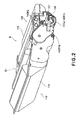
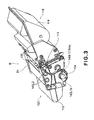
- Figures 2 and 3 are perspective views of the cartridge B.
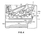
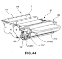
- Figure 4 is a sectional view of an electrophotographic image forming apparatus main assembly A (hereinafter referred to as an "apparatus main assembly A").
- the apparatus main assembly A corresponds to a portion of the electrophotographic image forming apparatus from which the cartridge B is excluded.
- the cartridge B includes an electrophotographic photosensitive drum 107.
- the photosensitive drum 107 is rotated by receiving a rotational force from the apparatus main assembly A by a coupling mechanism when the cartridge B is mounted in the apparatus main assembly A as shown in Figure 4 .
- the cartridge B is mountable to and demountable from the apparatus main assembly A by a user.
- a charging roller 108 as a charging means is provided in contact with an outer peripheral surface of the photosensitive drum 107.
- the charging roller 108 electrically charges the photosensitive drum 107 by voltage application from the apparatus main assembly A.
- the charging roller 108 is rotated by the rotation of the photosensitive drum 107.
- the cartridge B includes a developing roller 110 as a developing means (process means).
- the developing roller 110 supplies a developer to a developing area of the photosensitive drum 107.
- the developing roller 110 develops an electrostatic latent image formed on the photosensitive drum 107 with the developer t.
- the developing roller 110 contains therein a magnet roller (fixed magnet) 111.
- a developing blade 112 is provided in contact with a peripheral surface of the developing roller 110.
- the developing blade 112 defines an amount of the developer t to be deposited on the peripheral surface of the developing roller 110.
- the developing blade 112 imparts triboelectric charges to the developer t.
- the developer t contained in a developer accommodating container 114 is sent to a developing chamber 113a by rotation of stirring members 115 and 116, so that the developing roller 110 supplied with a voltage is rotated. As a result, a developer layer to which the electric charges are imparted by the developing blade 112 is formed on the surface of the developing roller 110.
- the developer t is transferred onto the photosensitive drum 107 depending on the latent image. As a result, the latent image is developed.
- the developer image formed on the photosensitive drum 107 is transferred onto a recording medium 102 by a transfer roller 104.
- the recording medium 102 is used for forming an image of the developer thereon and, e.g., is recording paper, label, OHP sheet, and so on
- an elastic cleaning blade 117a as a cleaning means is disposed in contact with the outer peripheral surface of the photosensitive drum 107.
- the cleaning blade 117a elastically contacts the photosensitive drum 107 at its end and removes the developer t remaining on the photosensitive drum 107 after the developer image is transferred onto the recording medium 102.
- the developer t removed from the surface of the photosensitive drum 107 by the cleaning blade 117a is accommodated in a removed developer reservoir 117b.
- the cartridge B is integrally constituted by a first frame unit 119 and a second frame unit 120.
- the first frame unit.119 is constituted by a first frame 113 as a part of a cartridge frame B1.
- the first frame unit 119 includes the developing roller 110, the developing blade 112, the developing chamber 113a, the developer accommodating container 114, and the stirring members 115 and 116.
- the second frame unit 120 is constituted by a second frame 118 as a part of the cartridge frame B1.
- the second frame unit 120 includes the photosensitive drum 107, the cleaning blade 117a, the removed developer reservoir 117b, and the charging roller 108.
- the first frame unit 119 and the second frame unit 120 are rotatably connected with each other by a pin P.
- an elastic member 135 ( Figure 3 ) provided between the first and second frame units 119 and 120, the developing roller 110 is pressed against the photosensitive drum 107.
- the user attaches (mounts) the cartridge B to a cartridge mounting portion 130a of the apparatus main assembly A by gripping a grip.
- a driving shaft 180 ( Figure 17 ) of the apparatus main assembly A and a coupling member 150 (described later) as a rotational force transmitting part of the cartridge B are connected with each other in synchronism with the mounting operation of the cartridge B.
- the photosensitive drum 107 or the like is rotated by receiving the rotational force from the apparatus main assembly A.
- the surface of the rotating photosensitive drum 107 is electrically charged uniformly by the charging roller 108. Then, the surface of the photosensitive drum 107 is irradiated with laser light, depending on image information, emitted from an optical means 101 including unshown members such as a laser diode, a polygonal mirror, a lens, and a reflecting mirror. As a result, on the photosensitive drum 107, an electrostatic latent image depending on the image information is formed. The latent image is developed by the above described developing roller 110.
- the recording medium 102 set in a cassette 103a is conveyed to a transfer position by a feeding roller 103b and conveying roller pairs 103c, 103d and 103e.
- the transfer roller 104 as a transfer means is disposed.
- a voltage is applied to the transfer roller 104.
- the developer image formed on the photosensitive drum 107 is transferred onto the recording medium 102.
- the recording medium 102 onto which the developer image is transferred is conveyed to a fixing means 105 through a guide 103f.
- the fixing means 105 includes a driving roller 105c and a fixing roller 105b containing therein a heater 105a.
- heat and pressure are applied, so that the developer image is fixed on the recording medium 102.
- an image is formed on the recording medium 102.
- the recording medium 102 is conveyed by roller pairs 103g and 103h and discharged on a tray 106.
- the above described roller 103b, the conveying roller pairs 103c, 103d and 103e, the guide 103f, the roller pairs 103g and 103h, and the like constitute a conveying means 103 for conveying the recording medium 102.
- the cartridge mounting portion 130a is a portion (space) for mounting the cartridge B therein.
- the coupling member 150 (described later) of the cartridge B is connected with the driving shaft of the apparatus main assembly A.
- the mounting of the cartridge B to the mounting portion 130a is referred to as mounting of the cartridge B to the apparatus main assembly A.
- demounting (removal) of the cartridge B from the mounting portion 130b is referred to as demounting of the cartridge B from the apparatus main assembly A.
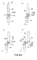
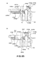
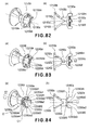
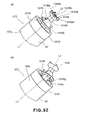
- FIG. 5(a) is a perspective view of the drum flange at the drive side
- Figure 5(b) is a sectional view of the drum flange taken along S1 - S1 line shown in Figure 5(a) .
- a side opposite from the drive side is referred to as a "non- drive side”).
- a drum flange 151 is formed of a resinous material by ejection molding.
- the resinous material may include polyacetal, polycarbonate, and so on
- a drum shaft 153 is formed of a metallic material such as iron, stainless steel, or the like.
- the drum flange 151 may also be formed of the metallic material and the drum shaft 153 may also be formed of the resinous material.
- both of the drum flange 151 and the drum shaft 153 are formed of the resinous material, they can be integrally molded.
- the flange 151 is provided with an engaging portion 151a which engages with an inner surface of the photosensitive drum 107, a gear portion (helical gear or spur gear) 151c for transmitting a rotational force to the developing roller 110, and an engaging portion 151d rotatably supported on a drum bearing. More specifically, as for the flange 151, the engaging portion 151a engages with one end of a cylindrical drum 107a as will be described hereinafter. These are disposed co-axially with a rotation axis L1 of the photosensitive drum 107. And, the drum engaging portion 151a has a cylindrical shape, and a base 151b perpendicular thereto is provided.
- the base 151b is provided with a drum shaft 153 outwardly projected with respect to the direction of the axis L1.
- This drum shaft 153 is co-axial with the drum engaging portion 151a. These are fixed so as to be co-axial with the rotation axis L1.
- the fixing method thereof the press-fitting, the bonding, the insert molding, and so on are available, and they are selected properly.
- the drum shaft 153 comprises the circular column portion 153a which has a projection configuration, and is disposed so as to be co-axially with the rotation axis of the photosensitive drum 107.
- the drum shaft 153 is provided on the end part of the photosensitive drum 107 on the axis L1 of the photosensitive drum 107.
- the drum shaft 153 is about 5 - 15mm in diameter in consideration of the material, the load, and the space.
- a free end portion 153b of the circular column portion 153a has a semi-spherical surface configuration so that it can incline smoothly, when an axis of a drum coupling member 150 which is a rotating force transmitting portion inclines, as will be described in detail hereinafter.
- a rotating force transmitting pin (rotating force receiving member (portion) 155 are provided on the photosensitive drum 107 side of the free end of the drum shaft 153.
- the pin 155 is extended in the direction substantially perpendicular to the axis of the drum shaft 153.
- the pin 155 as the rotational force receiving member has a cylindrical shape which has a diameter smaller than that of the circular column portion 153a of the drum shaft 153, and is made of the metal or the resin material. And, it is fixed by press-fitting, bonding, and so on to the drum shaft 153. And, the pin 155 is fixed in the direction which the axis thereof intersects the axis L1 of the photosensitive drum 107. Preferably, it is desirable to dispose the axis of the pin 155 so as to pass the center P2 of the spherical surface of the free end portion 153b of the drum shaft 153 ( figure 5 (b) ).
- the center P2 is the center of a phantom spherical surface that the semispherical surface makes the part thereof.
- the number of the pins 155 can be selected properly. In this embodiment, a single pin 155 is used from the standpoint of the assembling property and in order to transmit driving torque assuredly.
- the pin 155 passes said center P2, and is through the drum shaft 153.
- the pin 155 is outwardly projected at the positions of the peripheral surface of the drum shaft 153 which are diametrically opposite (155a1, 155a2).
- the pin 155 is projected in the direction perpendicular to the axis (axis L1) of the drum shaft 153 relative to the drum shaft 153 at the two opposite places (155a1, 155a2). By this, the drum shaft 153 receives the rotational force from the drum coupling member 150 at the two places.
- the pin 155 is mounted to the drum shaft 153 in the range of 5mm from the free end of the drum shaft 153. However, this does not limit the present invention.
- a space portion 151e formed by the engaging portion 151d and the base 151b receives a part of drum coupling member 150, in mounting the drum coupling member 150 (which will be described hereinafter) to the flange 151.
- the gear portion 151a for transmitting the rotational force to the developing roller 110 is mounted to the flange 151.
- the rotation of the developing roller 110 may be transmitted not through the flange 151.
- the gear portion 151c is unnecessary.
- integral molding, with the flange 151, of the gear portion 151a can be utilized.
- the flange 151, the drum shaft 153, and the pin 155 function as the rotational force receiving member which receives the rotational force from the drum coupling member 150 as will be described hereinafter.
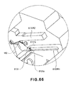
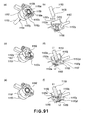
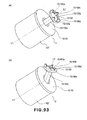
- FIG. 6 (a) is a perspective view, as seen from the driving side, of the drum unit U1
- Figure 6 (b) is a perspective view as seen from the non-driving side.
- Figure 7 is a sectional view taken along S2-S2 of Figure 6 (a) .
- the photosensitive drum 107 has a cylindrical drum 107a coated with a photosensitive layer 107b on the peripheral surface.
- the cylindrical drum 107a has an electroconductive cylinder, such as the aluminum, and the photosensitive layer 107b applied thereon. The opposite ends thereof are provided with the drum surface and the substantially co-axial opening 107a1, 107a2, in order to engage the drum flange (151, 152). More particularly, the drum shaft 153 is provided on the end part of the cylindrical drum 107a co-axially with the cylindrical drum 107a.
- Designated by 151c is a gear and transmits a rotational force which the coupling 150 received from a drive shaft 180 to a developing roller 110.
- the gear 151c is integrally molded with the flange 15.
- the cylinder 107a may be hollow or solid.
- a drum flange 152 of the non-driving side is made of the resin material similarly to the driving side with injection molding. And, a drum engaging portion 152b and a bearing portion 152a are substantially co-axially disposed with each other.
- the flange 152 is provided with a drum grounding plate 156.
- the drum grounding plate 156 is an electroconductive thin plate (metal).
- the drum grounding plate 156 includes contact portions 156b1, 156b2 which contact the inner surface of the electroconductive cylindrical drum 107a, and a contact portion 156a which contacts the drum grounding shaft 154 (which will be described hereinafter). And, for the purpose of grounding the photosensitive drum 107, the drum grounding plate 156 is electrically connected with the apparatus main assembly A.
- a drum flange 152 of the non-driving side is made of the resin material, similarly to the driving side with injection molding. And, a drum engaging portion 152b and a bearing portion 152a are substantially co-axially disposed with each other.
- the flange 152 is provided with a drum grounding plate 156.
- the drum grounding plate 156 is an electroconductive thin plate (metal).
- the drum grounding plate 156 includes contact portions 156b1, 156b2 which contact the inner surface of the electroconductive cylindrical drum 107a, and a contact portion 156a which contacts the drum grounding shaft 154 (which will be described hereinafter). And, for the purpose of grounding the photosensitive drum 107, the drum grounding plate 156 is electrically connected with the apparatus main assembly A.
- drum grounding plate 156 is provided in the flange 152, the present invention is not limited to such an example.
- the drum grounding plate 156 may be disposed at the drum flange 151, and it is possible to select properly the position which can be connected with the ground.
- the drum unit U1 comprises the photosensitive drum 107 which has the cylinder 107a, the flange 151, the flange 152, the drum shaft 153, the pin 155, and the drum grounding plate 156.
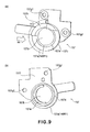
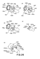
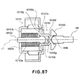
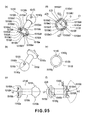
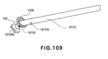
- Figure 8 is a perspective view, as seen from the apparatus main assembly side, of the drum coupling member
- Figure 8 (b) is a perspective view, as seen from the photosensitive drum side, of the drum coupling member
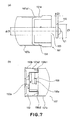
- Figure 8 (c) is a view seen in the direction perpendicular to the direction of the coupling rotation shaft L2.
- Figure 8 (d) is the side view, as seen from the apparatus main assembly side, of the drum coupling member
- Figure 8 (e) is the Figure, as seen from the photosensitive drum side
- Figure 8 (f) is a sectional view taken along S3 in Figure 8 (d) .
- the drum coupling member (“coupling") 150 engages with a drive shaft 180 ( Figure 17 ) of the apparatus main assembly A in the state where the cartridge B is mounted set to the installation section 130a. In addition, the coupling 150 is disengaged from the drive shaft 180, when the cartridge B is taken out from the apparatus main assembly A. And, the coupling 150 receives a rotational force from a motor provided in the apparatus main assembly A through the drive shaft 180 in the state where it is engaged with the drive shaft 180. In addition, the coupling 150 transmits the rotational force thereof to the photosensitive drum 107.
- the materials available for the coupling 150 are the resin materials, such as polyacetal and the polycarbonate PPS.
- the glass fibers, the carbon fibers, and so on may be mixed in the above described resin material correspondingly to a required load torque.
- the rigidity of the coupling 150 can be raised.
- the metal may be inserted, then the rigidity may further be raised, and the whole coupling may be manufactured from the metal and so on.
- the coupling 150 mainly comprises three portions.
- the first portion is engageable with the drive shaft 180 (which will be described hereinafter), and it is a coupling side driven portion 150a for receiving the rotational force from the rotational force transmitting pin 182 which is a rotational force applying portion (main assembly side rotational force transmitting portion) provided on the drive shaft 180.
- the second portion is engageable with the pin 155, and it is a coupling side driving portion 150b for transmitting the rotational force to the drum shaft 153.
- the third portion is a connecting portion 150c for connecting the driven portion 150a and the driving portion 150b with each other ( Figure 8 (c) and (f) ).
- the driven portion 150a, the driving portion 150b, and the connecting portion 150c may be molded integrally, or, alternatively, the separate parts may be connected with each other. In this embodiment, these are integrally molded with resin material. By this, the manufacturing of the coupling 150 is easy and the accuracy as the parts is high.
- the driven portion 150a is provided with a drive shaft insertion opening portion 150m which expands toward the rotation axis L2 of the coupling 150.
- the driving portion 150b has a drum shaft insertion opening portion 1501. which expands toward the rotation axis L2.
- the opening 150m has a conical driving shaft receiving surface 150f as an expanded part which expands toward the drive shaft 180 side in the state where the coupling 150 is mounted to the apparatus main assembly A.
- the receiving surface 150f constitutes a recess 150z as shown in Figure 8 (f) .
- the recess 150z includes the opening 150m at a position opposite the side adjecent the photosensitive drum 107 with respect to the direction of the axis L2.
- the coupling 150 can pivot among a rotational force transmitting angular position, a pre-engagement angular position, and a disengaging angular position relative to the axis L1 of the photosensitive drum 107 without being prevented by the free end portion of the drive shaft 180.
- the rotational force transmitting angular position, the pre-engagement angular position, and the disengaging angular position will be described hereinafter.
- a plurality of projections (the engaging portions) 150d1 - 150d4 are provided at equal intervals on a circumference about the axis L2 on an end surface of the recess 150z. Between the adjacent projections 150d 1, 150d 2, 150d3, 150d4, the standing-by portions 150k1, 150k2, 150k3, 150k4 are provided. An intervals between the adjacent projections 150d1 - 150d4 is larger than the outer diameter of the pin 182, so that the rotational force transmitting pins of the drive shaft 180 provided in the apparatus main assembly A (rotational force applying portions) 182 are received. The recesses between the adjacent projections are the standing-by portions 150k1-k4.
- the transmission pins 182a1, 182a2 are received by any of the standing-by portions 150k1-k4.
- the rotational force reception surfaces (rotational force receiving portions) 150e crossing with a rotational direction of the coupling 150 and (150e1-150e4) are provided in the downstream with respect to the clockwise direction (X1) of each projection 150d. More particularly, the projection 150d1 has a receiving surface 150e1, the projection 150d2 has a receiving surface 150e2, the projection 150d3 has a receiving surface 150e3, and, and, a projection 150d4 has a receiving surface 150e4.
- the pin 182a1, 182a2 contacts to any of the receiving surface 150e1-150e4.
- the receiving surface 150e contacted by the pin 182a1, 182a2 is pushed by the pin 182.
- the coupling 150 rotates about the axis L2.
- the receiving surface 150e1-150e4 is extended in the direction crossing with the rotational direction of the coupling 150.
- the rotational force receiving surfaces 150e are disposed on the same circumference that has the center on the axis L2. By this, the rotational force transmission radius is constant and the running torque transmitted to the coupling 150 is stabilized.
- the projections 150d1-150d4 it is preferable that the position of the by coupling 150 is stabilized by the balance of the forces which the coupling receives. For that reason, in this embodiment, the receiving surfaces 150e are disposed at the diametrically opposed positions (180 degrees).
- the receiving surface 150e1 and the receiving surface 150e3 are diametrically opposed relative to each other, and the receiving surface 150e2 and the surface 150e4 are diametrically opposed relative to each other ( Figure 8 (d) ).
- the forces which the coupling 150 receives constitute a force couple. Therefore, the coupling 150 can continue rotary motion only by receiving the force couple. For this reason, the coupling 150 can rotate without the necessity of being specified in the position of the rotation axis L2 thereof.
- the number thereof as long as the pins 182 of the drive shaft 180 (the rotational force applying portion) can enter the standing-by portions 150k1-150k2, it is possible to select suitably.
- the four receiving surfaces are provided.
- This embodiment is not limited to this example.
- the receiving surfaces 150e projections 150d1-150d4 do not need to be disposed on the same circumference (the phantom circle C1 and Figure 8(d) ). Or, it is not necessary to dispose at the diametrically opposed positions.
- the effects described above can be provided by disposing the receiving surfaces 150e as described above.
- the diameter of the pin is approximately 2 mm
- a circumferential length of the stand-by portion 150k is approximately 8 mm.
- the circumferential length of the stand-by portion 150k is an interval between adjacent projections 150d (on the phantom circle). The dimensions are not limiting to the present invention.
- a drum shaft insertion opening portion 1501 has a conical rotational force receiving surface 150i of an as an expanded part which expands toward the drum shaft 153 in the state where it is mounted to the cartridge B.
- the receiving surface 150i constitutes a recess 150q, as shown in Figure 8 (f) .
- the coupling 150 can pivot among a rotational force transmitting angular position, a pre-engagement angular position, and a disengaging angular position to the drum axix L1 without being prevented by the free end portion of the drum shaft 153.
- the recess 150q is constituted in the illustrated example by a conical receiving surface 150i which it has centering on the axis L2.
- the standby openings 150g 1 or 150g2 (“opening") are provided in the receiving surface 150i ( Figure 8b ).
- the pins 155 can be inserted into the inside of this opening 150g 1 or 150g2 so that it may be mounted to the drum shaft 153.
- the size of the openings 150g 1 or 150g2 is larger than the outer diameter of the pin 155.
- the projection 150d is provided adjacent to the free end of the recess 150z. And, the projections (projections) 150d project in the intersection direction crossing with the rotational direction in which the coupling 150 rotates, and are provided with the intervals along the rotational direction. And, in the state where the cartridge B is mounted to the apparatus main assembly A, the receiving surfaces 150e engage to or abutted to the pin 182, and are pushed by the pin 182.
- the receiving surfaces 150e receive the rotational force from the drive shaft 180.
- the receiving surfaces 150e are disposed in equidistant from the axis L2, and constitute a pair interposing the axis L2 they are constituted by the surface in the intersection direction in the projections 150d.
- the standing-by portions (recesses) 150k are provided along the rotational direction, and they are depressed in the direction of the axis L2.
- the standing-by portion 150k is formed as a space between the adjacent projections 150d.
- the pin 182 enters the standing-by portion 150k, and it stands by for being driven. And, when the drive shaft 180 rotates, the pin 182 pushes the receiving surface 150e.
- the rotational force receiving surface (rotational force receiving member (portion)) 150e may be disposed inside of the driving shaft receiving surface 150f. Or, the receiving surface 150e may be provided in the portion outwardly projected from the receiving surface 150f with respect to the direction of the axis L2. When the receiving surface 150e is disposed inside of the receiving surface 150f, the standing-by portion 150k is disposed inside of the receiving surface 150f
- the standing-by-portion 150k is the recess provided between the projections 150d in the inside of the arc part of the receiving surface 150f.
- the standing-by portion 150k is the recess positioned between the projections 150d.
- the recess may be a through hole extended in the direction of the axis L2, or it may be closed at one end thereof. More particularly, the recess is provided by the space region provided between the projection 150d. And, what is necessary is just to be able to enter the pin 182 into the region in the state where the cartridge B is mounted to the apparatus main assembly A.
- the rotational force transmission surfaces (the rotational force transmitting portions) 150h and (150h 1 or 150h2) are provided in the upstream, with respect to the clockwise direction (X1), of the opening 150g 1 or 150g2. And, the rotational force is transmitted to the photosensitive drum 107 from the coupling 150 by the convection sections 150h 1 or 150h2 contacting to any of the pins 155a1, 155a2. More particularly, the transmitting surfaces 150h 1 or 150h2 push the side surface of the pin 155. By this, the coupling 150 rotates with the center thereof aligned with the axis L2. The transmitting surface 150h 1 or 150h2 is extended in the direction crossing with the rotational direction of the coupling 150.
- the connecting portion 150c may become thin. This is because the coupling is manufactured so that the driving force receiving portion 150a, the driving portion 150b and the connecting portion 150c have a substantially uniform thickness. When the rigidity of the connecting portion 150c is insufficient, therefore, it is possible to make the connecting portion 150c thick so that driven portion 150a, the driving portion 150b, and the connecting portion 150c have the substantially equivalent thickness.
- Figure 9 is a perspective view, as seen from a drive shaft side
- Figure 9 (b) is a perspective view, as seen from the photosensitive drum side.
- the drum bearing member 157 rotatably supports the photosensitive drum 107 on the second frame 118.
- the bearing member 157 has a function of positioning the second frame unit 120 in the apparatus main assembly A. Further, it has the function of retaining the coupling 150 so that the rotational force can be transmitted to the photosensitive drum 107.
- an engaging portion 157d positioned to the second frame 118 and a peripheral part 157c positioned in the apparatus main assembly A are substantially co-axially disposed.
- the engaging portion 157d and the peripheral part 157c are annular.
- the coupling 150 is disposed in the space portion 157b inside thereof.
- the engaging portion 157d and the peripheral part 157c are provided with a rib 157e for retaining the coupling 150 in the cartridge B in the neighborhood of the central portion with respect to the axial direction.
- the bearing member 157 is provided with holes 157g 1 or 157g2 which penetrate the abutment surface 157f and the fixing screw for fixing the bearing member 157 to the second frame 118.
- the guide portion 157a for mounting and demounting on and the cartridge B relative to the apparatus main assembly A is integrally provided on the bearing member 157.
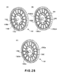
- Figure 10 (a) is an enlarged view, as seen from the driving side surface, of the major part around the photosensitive drum.
- Figure 10 (b) is an enlarged view, as seen from the non-driving side surface, of the major part.
- Figure 10 (c) is a sectional view taken along S4-S4 of Figure 10 (a) .
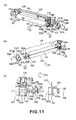
- Figure 11 (a) and (b) are an exploded perspective views which illustrate the state before attachment of the primary members of the second frame unit.
- Figure 11 (c) is a sectional view taken along S5-S5 in Figure 11 (a) .
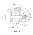
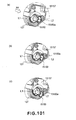
- Figure 12 is a sectional view which illustrates a state after attaching.
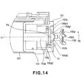
- Figure 13 is a sectional view taken along S6-S6 of Figure 11 (a) .
- Figure 14 is a sectional view which illustrates a state after rotating the coupling and the photosensitive drum through 90 degrees from the state of Figure 13 .
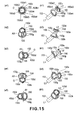
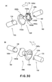
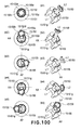
- Figure 15 is a perspective view which illustrates the combined state of the drum shaft and the coupling.
- Figure 15(a1)-(a5) are front views, as seen from the axial direction of the photosensitive drum, and
- Figure 15(b1)-(b5) are perspective views.
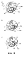
- Figure 16 is a perspective view which illustrates the state where the coupling is inclined in the process cartridge.
- the coupling 150 is mounted so that the axis L2 thereof can incline in any direction relative to the axis L1 of the drum shaft 153 (coaxial with the photosensitive drum 107).
- the inclination is made by combining the rotations in the axes AX and the directions of AY.
- the axis L2 can be pivoted in any direction relative to the axis L1.
- the transmitting surface (rotational force transmitting portion) 150h is movable relative to the pin (rotational force receiving portion) 155.
- the pin 155 has the transmitting surface 150 in the movable condition.
- the transmitting surface 150h and the pin 155 are engaged to each other in the rotational direction of the coupling 150.
- the coupling 150 is mounted to the cartridge.
- the gap is provided between the transmitting surface 150h and the pin 155.
- the coupling 150 is pivotable in all directions substantially relative to the axis L1.
- the opening 150g is extended in the direction (the rotational axis direction of the coupling 150) crossing with the projection direction of the pins 155 at least. Therefore, as has been described hereinbefore, the coupling 150 is pivotable in all the directions.
- the axis L2 is slantable or inclinable in any direction relative to the axis L1.
- the axis L2 does not necessarily need to be linearly slantable to the predetermined angle in the full range of 360-degree direction in the coupling 150.
- the opening 150g can be selected to be slightly wider in the circumferential direction. By doing so, the time of the axis L2 inclining relative to the axis L1, even if it is the case where it cannot incline to the predetermined angle linearly, the coupling 150 can rotate to a slight degree around the axis L2. Therefore, it can be inclined to the predetermined angle. In other words, the amount of the play in the rotational direction of the opening 150g is selected properly if necessary.
- the coupling 150 is revolvable or swingable over the full-circumference substantially relative to drum shaft (rotational force receiving member) 153. More particularly, the coupling 150 is pivotable over the full-circumference thereof substantially relative to the drum shaft 153.
- the coupling 150 is capable of whirling in and substantially over the circumferential direction of the drum shaft 153.
- the whirling motion is not a motion with which the coupling itself rotates about the axis L2, but the inclined axis L2 rotates about the axis L1 of the photosensitive drum, although the whirling here does not preclude the rotation of the coupling per se about the axis L2 of the coupling 150.
- the photosensitive drum 107 is mounted in the direction X1 in Figure 11 (a) and Figure 11 (b) .
- the bearing portion 151d of the flange 151 is made to substantially co-axially engage with the centering portion 118h of the second frame 118.
- bearing hole 152a Figure 7 of the flange 152 (a)) is substantially co-axially engaged with the centering portion 118g of the second frame 118.
- the drum grounding shaft 154 is inserted into the direction X2. And, the centering portion 154b is penetrated through the bearing hole 152a ( Figure 6b ) and the centering hole 118g ( Figure 10 (b) ). At this time, the centering portion 154b and the bearing hole 152a are supported so that the photosensitive drum 107 is rotatable. On the other hand, the centering portion 154b and.the centering hole 118g are supported fixedly by the press-fitting and so on. By this, the photosensitive drum 107 is rotatably supported relative to the second frame. Alternatively, it may be fixed non-rotatably relative to the flange 152, and the drum grounding shaft 154 (centering portion 154b) may be rotatably mounted to the second frame 118.
- the coupling 150 and the bearing member 157 are inserted in the direction X3.
- the driving portion 150b is inserted toward the direction X3 downstream, while maintaining the axis L2 ( Figure 11c ) in parallel with X3.
- the phase of the pin 155 and the phase of the opening 150g are matched with each other, and the pin 155 is made inserted into the openings 150g 1 or 150g2.
- the free end portion 153b of the drum shaft 153 is abutted to the drum bearing surface 150i.
- the free end potion 153b is the spherical surface and the drum bearing surface 150i is a conic surface.
- the pin 155 positioned in the opening 150g will be pushed by the rotational force transmission surfaces (the rotational force transmitting portions) 150h 1 or 150h2 and ( Figure 8b ). By this, the rotational force is transmitted to the photosensitive drum 107. Thereafter, the engaging portion 157d is inserted downstream with respect to the direction X3.
- the engaging portion 157d supports the bearing portion 151d of the flange 151, so that the photosensitive drum 107 is rotatable.
- the engaging portion 157d engages with the centering portion 118h of the second frame 118.
- the abutment surface 157f of the bearing member 157 abuts to the abutment surface 118j of the second frame 118.
- the screws 158a, 158b are penetrated.through the holes 157g 1 or 157g2, and they are fixed to the screw holes 118k1, 118k2 of the second frame 118, so that the bearing member 157 is fixed to the second frame 118 ( Figure 12 ).
- a maximum outer diameter of the driven portion 150a is ⁇ D2
- a maximum outer diameter of the driving portion 150b is ⁇ D1
- a small diameter of the standby opening 150g is ⁇ D3.
- a maximum outer diameter of the pin 155 is ⁇ D5
- an inner diameter of the retention rib 157e of the bearing member 157 is ⁇ D4.
- the maximum outer diameter is the outer diameter of a maximum rotation locus about the axis L1 or the axis L2.
- the coupling 150 can be assembled to the predetermined position by the straight mounting operation in the direction X3 therefore, the assembling property is high (the state after the assembly is shown in Figure 12 ).
- the diameter of the inner surface ⁇ D4 of the retention rib 157e of the bearing member 157 is larger than ⁇ D2 of the coupling 150, and smaller than ⁇ D1 ( ⁇ D2 ⁇ ⁇ D4 ⁇ ⁇ D1).
- the retention rib 157e of the bearing member 157 is disposed closely to a flange portion 150j of the coupling 150 in the direction of the axis L1. More specifically, in the direction of the axis L1, the distance from an end surface 150j1 of the flange portion 150j to the axis L4 of the pin 155 is n1. In addition, the distance from an end surface 157el of the rib 157e to the other end surface 157j2 of the flange portion 150j is n2. The distance n2 ⁇ distance n1 is satisfied.
- the flange portion 150j and the rib 157e are disposed so that they are overlapped relative to each other. More specifically, the distance n4 from the inner surface 157e3 of the rib 157e to the outer surface 150j3 of the flange portion 150j is the overlap amount n4 with respect to the orthogonality direction of the axis L1.
- the pin 155 is prevented from disengaging from the opening 150g. That is, the movement of the coupling 150 is limited by the bearing member 157. Thus, the coupling 150 does not disengage from the cartridge. The prevention of disengagement can be accomplished without additional parts.
- the dimensions described above are desirable from the standpoint of reduction of manufacturing and assemblying costs. However, the present invention is not limited to these dimensions.
- the receiving surface 150i which is the recess 150q of the coupling 150 is in contact with the free end surface 153b of the drum shaft 153 which is the projection. Therefore, the coupling 150 is swung along the free end portion (the spherical surface) 153b about the center P2 of the free end portion (the spherical surface) 153b in other words, the axis L2 is pivotable substantially in all directions irrespective of the phase of the drum shaft 153.
- the axis L2 of the coupling 150 is pivotable in all directions substantially.
- the axis L2 is inclined toward the downstream with respect to the mounting direction of the cartridge B relative to the axis L1, just before the engagement.
- the axis L2 inclines so that the driven portion 150a positions at the downstream side with respect to the mounting direction X4 relative to the axis L1 of the photosensitive drum 107 (the drum shaft 153).
- Figures 16 (a)-(c) although the positions of the driven portion 150a slightly differ relative to each other, they are positioned at the downstream side with respect to the mounting direction X4 in any case.
- a distance n3 between a maximum outer diameter part and bearing member 157 of the driving portion 150b is selected so that a slight gap is provided between them.
- the rib 157e is a semi-circular rib.
- the rib 157e is disposed at the downstream with respect to the mounting direction X4 of the cartridge B. Therefore, as shown in Figure 10 (c) , the driven portion 150a side of the axis L2 is greatly pivotable in the direction X4. In other words, the driving portion 150b side of the axis L2 is greatly pivotable in the direction of angle ⁇ 3) at phase ( Figure 9(a) at which the rib 157e is not disposed.
- Figure 10 (c) illustrates the state where the axis L2 inclined.
- the rib 157e is disposed.
- the coupling 150 can be mounted by the simple method to the cartridge B.
- the axis L2 is pivotable relative to the axis L1.
- the rib is not limited to the semi-circular rib. As long as the coupling 150 is pivotable to the predetermined direction, and it is possible to mount the coupling 150 to Cartridge B (photosensitive drum 107), any rib is usable. In this manner, the rib 157e has a function as the regulating means for regulating the inclining direction of the coupling 150.
- a distance n2 ( Figure 12 ) in the direction of the axis L1 from the rib 157e to the flange portion 150j is shorter than a distance n1 from the center of the pin 155 to the driving portion 150b side edge. By this, the pin 155 does not disengage from the opening 150g.
- the coupling 150 is supported by the both of the drum shaft 153 and the drum bearing 157 substantially. More particularly, the coupling 150 is mounted to the cartridge B by the drum shaft 153 and the drum bearing 157 substantially.
- the coupling 150 has a play (the distance n2) in the direction of the axis L1 relative to the drum shaft 153. Therefore, the receiving surface 150i (the conic surface) may not contact snuggly the drum shaft free end portion 153b (the spherical surface). In other words, the center of the pivoting may deviate from the center of curvature P2 of the spherical surface. However, even in such a case, the axis L2 is pivotable relative to the axis L1. For this reason, the purpose of this embodiment can be accomplished.
- maximum possible inclination angle ⁇ 4 ( Figure 10 (c) ) between the axis L1 and the axis L2 is the one half of the taper angle ( ⁇ 1, Figure 8(f) ) between the axis L2 and the receiving surface 150i.
- the receiving surface 150i has conical shape and the drum shaft 153 has the cylindrical shape. For this reason, the gap g of angle ⁇ 1/2 is provided between them.
- the taper angle ⁇ 1 changes, and therefore, the inclination angle ⁇ 4 of the coupling 150 are set to the optimal value.
- the receiving surface 150i is the conic surface
- the circular column portion 153a of the drum shaft 153 is satisfactory with the simple cylindrical shape. In other words, the drum shaft does not need to have a complicated configuration. Therefore, the machining cost of the drum shaft can be suppressed.
- the coupling 150 is mounted so that a part of a coupling 150 may locate at the position which overlaps the gear portion 151c with respect to the direction of the axis L2. In the case of the flange which does not have the gear portion 151c, a part of coupling 150 can further enter into the cylinder 107a.
- the width of the opening 150g is selected in consideration of the size of the pin 155 so that the pin 155 may not interfere.
- the transmitting surface (rotational force transmitting portion) 150h is movable relative to the pin (rotational force receiving portion) 155.
- the pin 155 has the transmitting surface 150 in the movable condition.
- the transmitting surface 150h and the pin 155 are engaged to each other in the rotational direction of the coupling 150.
- the coupling 150 is mounted to the cartridge.
- the gap is provided between the transmitting surface 150h and the pin 155.
- the coupling 150 is pivotable in all directions substantially relative to the axis L1.
- the locus of the flange portion 150j when the driven portion 150a side inclines in the direction X5 is illustrated by the region T1 in Figure 14 .
- the flange portion 150j can be provided over the full-circumference of the coupling 150 ( Figure 8 (b) ).
- the shaft receiving surface 150i has conical shape, and therefore, when the coupling 150 inclines, the pin 155 does not enter in the region T1. For this reason, the cutting away range of the coupling 150 is minimized. Therefore, the rigidity of the coupling 150 can be assured.
- the process (the non-driving side) in the direction X2 and the process (the driving side) in the direction X3 may be exchanged.
- the bearing member 157 has been described as being fixed on the screws to the second frame 118. However, the present invention is not limited to such an example. For example, like the bonding, if the bearing member 157 is fixable to the second frame 118, the any method will be usable.
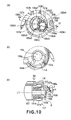
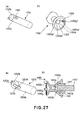
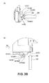
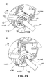
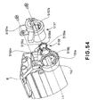
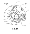
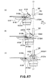
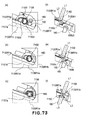
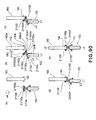
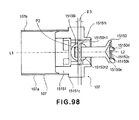
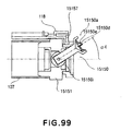
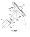
- Figure 17 is a partly broken perspective view of the side plate of the driving side in the state where the cartridge B is not mounted to the apparatus main assembly A.
- Figure 17 (b) is a perspective view which illustrates only the drum driving structure.
- Figure 17 (c) is the sectional view taken along S7-S7 of Figure 17 (b) .
- the drive shaft 180 has the substantially similar structure as the above described drum shaft 153.
- the free end portion 180b thereof forms a semispherical surface.
- it has a rotational force transmitting pin 182 as a rotational force applying portion of the main part 180a of the cylindrical shape which penetrates the center substantially. The rotational force is transmitted to the coupling 150 by this pin 182.
- a drum driving gear 181 substantially co-axial with the axis of the drive shaft 180 is provided on the longitudinally opposite side of the free end portion 180b of the drive shaft 180.
- the gear 181 is fixed non-rotatably relative to the drive shaft 180. Therefore, the rotation of the gear 181 will also rotate the drive shaft 180.
- the gear 181 is engaged with a pinion gear 187 for receiving the rotational force from the motor 186. Therefore, the rotation of the motor 186 will rotate the drive shaft 180 through the gear 181.
- the gear 181 is rotatably mounted to the apparatus main assembly A by the bearing members 183, 184.
- the gear 181 does not move relative to the direction of the axial direction L3 of the drive shaft 180 (the gear 181), that is, it is positioned with respect to the axial direction L3. Therefore, the gears 181 and the bearing members 183 and 184 can be closely disposed relative to each other with respect to the axial direction.
- the drive shaft 180 does not move with respect to the direction thereof of the axis L3. Therefore, the drive shaft 180 and the gap between the bearing members 183 and 184 have the sizes which permit the rotation of the drive shaft 180. For this reason, the position of the gear 181 with respect to the diametrical direction relative to the gear 187 is determined correctly.
- the drive is directly transmitted to the gear 181 from the gear 187
- the present invention is not limited to such an example.
- it is the satisfactory using a plurality of gears on account of the motor disposed at the apparatus main assembly A.
- the mounting means 130 of this embodiment includes main assembly guides 130R1, 130R2, 130L1, 130L2 provided in the apparatus main assembly A.
- the main assembly guides 130R1, 130R2 are provided in the main assembly opposed to the driving side of the cartridge B, and they are extended along the mounting direction of the cartridge B.
- the main assembly guides 130L1, 130L2 are provided in the main assembly side opposed to the non-driving side of the cartridge B, and they are extended along the mounting direction of the cartridge B.
- the main assembly guides 130R1, 130R2 and the main assembly guides 130L1, 130L2 are opposed to each other.
- the outer periphery 157a of the outside end of the bearing member 157 functions also as a cartridge guide 140R1.
- the outer periphery 154a of the outside end of the drum grounding shaft 154 functions also as a cartridge guide 140L1.
- the one longitudinal end (the driving side) of the second frame unit 120 is provided with the cartridge guide 140R2 on the upper portion of the cartridge guide 140R1.
- the other end (the non-driving side) in the longitudinal direction is provided with the cartridge guide 140L2 on the upper portion of the cartridge guide 140L1.
- the one longitudinal end of the photosensitive drum 107 is provided with the cartridge side guides 140R1, 140R2 outwardly projected from the cartridge frame B1.
- the other end in the longitudinal direction is provided with the cartridge side guides 140L1, 140L2 outwardly projected from the cartridge frame B1.
- the guides 140R1, 140R2, 140L1, 140L2 is projected toward the along said longitudinal direction here and there outside. More particularly, the guides 140R1, 140R2, 140L1, 140L2 are projected from the cartridge frame B1 along the axis L1. And, at the time of mounting the cartridge B to the apparatus main assembly A, and at the time of demounting the cartridge B from the apparatus main assembly A the guide 140R1 is guided by the guide 130R1, and the guide 140R2 is guided by the guide 130R2.
- the guide 140L1 is guided by the guide 130L1, and the guide 140L2 is guided by the guide 130L2.
- the cartridge B is mounted to the apparatus main assembly A, moving in the direction substantially perpendicular to the axial direction L3 of the drive shaft 180, and it is similarly demounted from the apparatus main assembly A.
- the cartridge guides 140R1, 140R2 are molded integrally with the second frame 118. However, separate members are usable as the cartridge guides 140R1, 140R2.
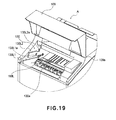
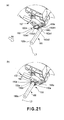
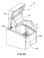
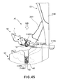
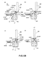
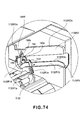
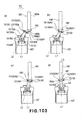
- Figure 20 shows the mounting process.
- Figure 20 is a sectional view taken along S9-S9 of Figure 18 .
- the door 109 is opened by the user.
- the cartridge B is dismountably mounted relative to the cartridge mounting means 130 (the installation section 130a) provided in the apparatus main assembly A.
- the cartridge guides 140R1, 140R2 are inserted along the main assembly guides 130R1, 130R2, as shown in Figure 20 (b) .
- the cartridge guides 140L1, 140L2 ( Figure 3 ) are inserted along the main assembly guides 130L1, 130L2 ( Figure 19 ).
- the cartridge guide 140R1 contacts to the positioning portion 130R1a of the main assembly guide 130R1, and the cartridge guide 140R2 contacts to the positioning portion 130R2a of the main assembly guide 130R2.
- the cartridge guide 140L1 contacts to the positioning portion 130L1a ( Figure 19 ) of the main assembly guide 130L1, and the cartridge guide 140L2 contacts to the positioning portion 130L2a of the main assembly guide 130L2 since this state is substantially symmetrical, the illustration is not made.
- the cartridge B is dismountably mounted to the installation section 130a by the mounting means 130. More particularly, the cartridge B is mounted in the state positioned in the apparatus main assembly A. And, in the state where the cartridge B is mounted to the installation section 130a, the drive shaft 180 and the coupling 150 are in the engaged state relative to each other.
- the coupling 150 is in a rotational force transmitting angular position as will be described hereinafter.
- the image forming operation is enabled by the cartridge B being mounted to the set portion 130a.
- a pressing receptor portion 140R1b ( Figure 2 ) of the cartridge B receives the urging force from an urging spring 188R ( Figure 18 , Figure 19 , and Figure 20 ).
- a pressing receptor portion 140L1b ( Figure 3 ) of the cartridge B receives the urging force.
- the user may enter the cartridge B to the set portion 130a as described above.
- the user enters the cartridge B to the position halfway, and the last mounting operation may be effected by another means.
- a part of door 109 acts on the cartridge B which is in the position in the course of the mounting to push the cartridge B into the final mounted position.
- the user pushes, into the cartridge B to the middle, the cartridge B, and lets it fall into the set portion 130a by the weight, after that.
- the mounting and demounting of the cartridge B relative to the apparatus main assembly A is effected by the movement in the direction substantially perpendicular to the .direction of the axis L3 of the drive shaft 180 ( Figure 21 ) corresponding to these operations, the position between the drive shaft 180 and the coupling 150 change between the engaged state and the disengagement state.
- the small gaps are provided. More specifically, the small gaps are provided $ between the guide 140R1 and the guide 130R1 with respect to the longitudinal direction, between the guide 140R2 and the guide 130R2 with respect to the longitudinal direction, between the guide 140L1 and the guide 130L1 with respect to the longitudinal direction, and between the guide 140L2 and the guide 130L2 with respect to the longitudinal direction. Therefore, at the time of the mounting and demounting of the cartridge B relative to the apparatus main assembly A, the whole cartridge B can slightly incline within the limits of the gaps. For this reason, the perpendicularity is not meant strictly. However, even in such a case, the present invention is accomplished with the effects thereof. Therefore, the term "perpendicular substantially" covers the case where the cartridge slightly inclines.
- the coupling 150 is engaged with the drive shaft 180. More particularly, the coupling 150 positions at the rotational force transmitting angular position.
- the predetermined position is the set portion 130a.
- Figure 21 is a perspective view which illustrates the major part of the drive shaft and the driving side of the cartridge.
- Figure 22 is a longitudinal sectional view, as seen from the lower part of the apparatus main assembly.
- Figure 23 is a longitudinal sectional view, as seen from the lower part of the apparatus main assembly.
- the engagement means the state in which the axis L2 and the axis L3 are substantially co-axial relative to each other, and the drive transmission is possible.
- the cartridge B is mounted to the apparatus main assembly A in the direction (arrow X4) substantially perpendicular to the axis L3 of the drive shaft 180. Or, it is demounted from the apparatus main assembly A.
- the axis L2 ( Figure 22 a ) of the coupling 150 inclines toward downstream with respect to the mounting direction X4 beforehand relative to the axis L1 ( Figure 22(a) of the drum shaft 153 ( Figure 21 a and Figure 22(a) .
- the downstream free end 150A1 with respect to the mounting direction X4 is closer to the photosensitive drum 107 than the drive shaft free end 180b3 in the direction of the axis L1.
- the upstream free end 150A2 with respect to the mounting direction is closer to the pin 182 than the drive shaft free end 180b3 ( Figure 22(a), (b) ).
- the free end position is the position nearest to the drive shaft of the driven portion 150a shown in Figure 8(a) and (c) with respect to the direction of the axis L2, and it is the remotest position from the axis L2.
- it is an edge line of the driven portion 150a of the coupling 150, or an edge line of the projection 150d depending on the rotation phase of the coupling 150 (150A) in Figure 8(a) and (c) .
- the free end position 150A1 of the coupling 150 passes by the drive shaft free end 180b3. And, after the coupling 150 carries out by passage of the drive shaft free end 180b3, the receiving surface (cartridge side contact portion) 150f or the projection (cartridge side contact portion) 150d contacts with the free end portion 180b of drive shaft (main assembly side engaging portion) 180, or pin (main assembly side engaging portion) (rotational force applying portion) 182. And, corresponding to the mounting operation of the cartridge (B), the axis L2 is inclined so that it may align substantially with the axis L1 ( Figure 22 (c) ).
- the coupling 150 inclines from said pre-engagement angular position and the axis L2 thereof aligns substantially with the axis L1, the rotational force transmitting angular position is reached.
- the position of the cartridge (B) is determined relative to the apparatus main assembly (A).
- the drive shaft 180 and the drum shaft 153 are substantially co-axial relative to each other.
- the receiving surface 150f opposes to the spherical free end portion 180b of the drive shaft 180.
- This state is the engaged state between the coupling 150 and the drive shaft 180 ( Figure 21 (b) and Figure 22 (d) ).
- the pin 155 (unshown) is positioned in the opening 150g ( Figure 8 (b) ).
- the pin 182 takes the standing-by portion 150k.
- the coupling 150 covers the free end portion 180b.
- the receiving surface 150f constitutes the recess 150z. And, the recess 150z has the conical shape.
- the coupling 150 is pivotable relative to the axis L1. And, corresponding to the movement of the cartridge (B), a part of coupling 150 (the receiving surface 150f and/or 150d of projections) which is the cartridge side contact portion contacts to the main assembly side engaging portion (the drive shaft 180 and/or the pin 182). By this, the pivoting motion of the coupling 150 is effected.
- the coupling 150 is mounted with the state of overlapping, with respect to the direction of the axis L1, with the drive shaft 180. However, the coupling 150 and the drive shaft 180 are engageable relative to each other with the overlapping state by the pivoting motion of the couplings, as described above.
- Figure 23 illustrates the phase relation between the coupling and the drive shaft.
- the pin 182 and the receiving surface 150f face to each other.
- the pin 182 and the projection 150d face to each other.
- the free end portion 180b and the projection 150d face to each other.
- the free end portion 180b and the receiving surface 150f face to each other.
- the coupling 150 is pivotably mounted in any direction relative to the drum shaft 153. More particularly, the coupling 150 is revolvable. Therefore, as shown in Figure 23 , it can incline toward the mounting direction X4 irrespective of the phase of the drum shaft 153 relative to the mounting direction X4 of the cartridge (B). In addition, the inclination angle of the coupling 150 is set, so that regardless of the phases of the drive shaft 180 and the coupling 150, the free end position 150A1 is made closer to the photosensitive drum 107 than the axial free end 180b3 with respect to the direction of the axis L1.
- the inclination angle of the coupling 150 is set, so that the free end position 150A2 is made closer to the pin 182 than the axial free end 180b3.
- the receiving surface 150f contacts the pin 182.
- the projection (the engaging portion) 150d contacts the pin (rotational force applying portion) 182.
- the projection 150d contacts to the free end portion 180b.
- the receiving surface 150f contacts to the free end portion 180b.
- the axis L2 of the coupling 150 moves so that it substantially becomes co-axial with the axis L1.
- the coupling 150 is engaged with the drive shaft 180.
- the coupling recess 150z covers the free end portion 180b. For this reason, the coupling 150 can be engaged with the drive shaft 180 (the pin 182) irrespective of the phases of the drive shaft 180, the coupling 150 and the drum shaft 153.
- the gap is provided between the drum shaft 153 and the coupling 150, so that the coupling is swingable (revolvable, pivotable).
- the coupling 150 moves in a plane of the sheet of the drawing of Figure 22 .
- the coupling 150 of this embodiment is capable of whirling, as described above. Therefore, the motion of the coupling 150 may include motion not included in the plane of the sheet of the drawing of Figure 22 . In such a case, the change from the state of Figure 22(a) to the state of Figure 22(d) occurs. This applies to the embodiments which will be described hereinafter unless otherwise stated.
- the drive shaft 180 rotates with the gear 181 in the direction ( Figure, X8) by the rotational force received from the driving source (the motor 186).
- the pin 182 integral with the drive shaft 180 (182a1, 182a2) contacts to any of the rotational force receiving surfaces (rotational force receiving portion) 150e1-150e4. More particularly, the pin 182a1 contacts any one of the rotational force receiving surfaces 150e1-150e4. In addition, the pin 182a2 contacts with any of the rotational force receiving surfaces 150e1-150e4. By this, the rotational force of the drive shaft 180 is transmitted to the coupling 150 to rotate the coupling 150.
- the rotational force transmission surfaces (the rotational force transmitting portion) 150h 1 or 150h2 of the coupling 150 contact to the pin 155 integral with the drum shaft 153.
- the rotational force of the drive shaft 180 is transmitted to the photosensitive drum 107 through the coupling 150, the rotational force transmission surface 150h 1 or 150h2, the pin 155, the drum shaft 153, and the drum flange 151. In this manner, the photosensitive drum 107 is rotated.
- the free end portion 153b is contacted with the receiving surface 150i.
- the free end portion (the positioning portion) 180b of the drive shaft 180 is contacted with the receiving surface (the positioning portion) 150f.
- the coupling 150 is positioned relative to the drive shaft 180 in the state where it is over the drive shaft 180 ( Figures 22(d) ).
- the coupling 150 can effect the transmission of the rotational force because the coupling 150 inclines slightly. Even if it is such a case, the coupling 150 can rotate without covering the large additional load over the drum shaft 153 and the drive shaft 180. Therefore, the high precision position arrangement operation of the drive shaft 180 and the drum shaft 153 at the time of the assembling is easy. For this reason, the assembling operativity can be improved.
- the position of the drive shaft 180 and the gear 181 is positioned with respect to the diametrical direction and the axial direction in the predetermined position (Set portion 130a) of the apparatus main assembly (A).
- the cartridge (B) is positioned in the predetermined position of the apparatus main assembly as described above.
- the drive shaft 180 positioned in said predetermined position and the cartridge (B) positioned in said predetermined position are coupled by the coupling 150.
- the coupling 150 is swingable (pivotable) relative to the photosensitive drum 107. For this reason, as described above, the coupling 150 can transmit the rotational force smoothly between the drive shaft 180 positioned in the predetermined position and the cartridge (B) positioned in the predetermined position. In other words, even if there is some axial deviation between the drive shaft 180 and the photoserisitive drum 107, the coupling 150 can transmit the rotational force smoothly.
- the cartridge (B) is positioned in the predetermined position. For this reason, the photosensitive drum 107 which is the constituent-element of the cartridge (B) is correctly positioned relative to the apparatus main assembly (A). Therefore, the spatial relationship between the photosensitive drum 107, and the optical means 101, the transfer roller 104 or recording material 102 can be maintained with high precision. In other words, those position deviations can be reduced.
- the coupling 150 contacts to the drive shaft 180.
- the coupling 150 swings from the pre-engagement angular position to the rotational force transmitting angular position
- the present invention is not limited to such an example.
- a part of coupling 150 (cartridge side contact portion) contacts with this abutting portion.
- the coupling can receive the force of the shaking direction (pivoting direction), and it can also be made to swing so that the axis L2 becomes substantially co-axial with the axis L3 (the pivoting).
- the axis L1 can substantially co-axially position with the axis L3 in interrelation with the mounting operation of the cartridge (B).
- Figure 25 is the longitudinal sectional view, as seen from the apparatus main assembly lower.
- the pin 182 is positioned at any 2 of the standing-by portions 150k1-150k4 ( Figure 8 ). And, the pin 155 is positioned in the opening 150g 1 or 150g2.
- the cartridge (B) is drawn out in the direction (the direction of the arrow X6) substantially perpendicular to the axis L3, at the time of demounting from the apparatus main assembly (A).
- the axis L2 is substantially co-axial relative to the axis L1 in the coupling 150 (rotational force transmitting angular position) ( Figure 25 (a) ).
- the drum shaft 153 moves in the dismounting direction X6 with the cartridge (B), and the receiving surface 150f or the projection 150d in the upstream of the coupling 150 with respect to the dismounting direction contacts at least to the free end portion 180b of the drive shaft 180( Figure 25 (a) ).
- the axis L2 begins to incline toward the upstream with respect to the dismounting direction X6 ( Figure 25 (b) ).
- This direction is the same as that of the inclination of the coupling 150 at the time of the mounting of the cartridge (B) (the pre-engagement angular position). It moves, while the upstream free end portion 150 A3 with respect to the dismounting direction X6 contacts to the free end portion 180b by the dismounting operation from the apparatus main assembly (A) of this cartridge (B).
- the coupling moves.
- the free end portion 150 A3 inclines to the free end 180b3 (disengaging angular position) ( Figure 25 (c) ). And, in this state, the coupling 150 is passed by the drive shaft 180, contacting to the free end 180b3, and is disengaged from the drive shaft 180 ( Figure 25 (d) ). Thereafter, the cartridge (B) follows the process opposite from that of the mounting process described in Figure 20 , and is taken out from the apparatus main assembly (A).
- the angle of the pre-engagement angular position relative to the axis L1 is larger than the angle of the disengaging angular position relative to the axis L1. This is because it is preferable that the free end position 150A1 passes assuredly by the free end portion 180b3 in the pre-engagement angular position in consideration of the dimensional tolerance of the parts at the time of the engagement of the coupling. More particularly, it is preferable that the gap exists between the coupling 150 and the free end portion 180b3 in the pre-engagement angular position ( Figure 22 (b) ).
- the cartridge (B) can be taken out irrespective of the phase difference between the coupling 150 and the pin 182.
- the angle relative to the axis L1 of the coupling 150 is such that in the state where the cartridge (B) is mounted to the apparatus main assembly (A), the coupling 150 receives the transmission of the rotational force from the drive shaft 180, and it rotates.
- the rotational force transmitting angular position of the coupling 150, the rotational force for rotating the photosensitive drum is transmitted to the drum.
- the angular position relative to the axis L1 of the coupling 150 is such that it is in the state immediately before the coupling 150 engages with the drive shaft 180 in the mounting operation to the apparatus main assembly (A) of the cartridge (B). More particularly, it is the angular position relative to the axis L1 which the downstream free end portion 150A1 of the coupling 150 can pass by the drive shaft 180 with respect to the mounting direction of the cartridge (B).
- the disengaging angular position of the coupling 150 is the angular position relative to the axis L1 of the coupling 150 at the time of taking out the cartridge (B) from the apparatus main assembly (A), in the case that the coupling 150 disengages from the drive shaft 180. More particularly, as shown in Figure 25 , it is the angular position relative to the axis L1 with which the free end portion 150 A3 of the coupling 150 can pass by the drive shaft 180 with respect to the removing direction of the cartridge (B).
- the angle theta 2 which the axis L2 makes with the axis L1 is larger than the angle theta 1 which the axis L2 makes with the axis L1 in the rotational force transmitting angular position.
- the angle theta 1 0 degree is preferable.
- the angle theta 1 is less than about 15 degrees, the smooth transmission of the rotational force is accomplished. This is also one of the effects of this embodiment.
- the angle theta 2 the range of about 20 - 60 degrees is preferable.
- the coupling is pivotably mounted to the axis L1. And, the coupling 150 in the state in which it overlaps with the drive shaft 180 with respect to the direction of the axis L1 can be disengaged from the drive shaft 180 because the coupling inclines correspondingly to the dismounting operation of the cartridge (B). More particularly, by moving the cartridge (B) in the direction substantially perpendicular to the axial direction of the drive shaft 180, the coupling 150 which covers the drive shaft 180 can be disengaged from the drive shaft 180.
- the receiving surface 150f of the coupling 150 or the projection 150d contacts with the free end portion 180b (the pin 182) in interrelation with the movement of the cartridge (B) in the dismounting direction X6.
- the axis L1 starts the inclination to the dismounting direction upstream.
- the coupling 150 has a structure beforehand, so that it is urged toward the upstream in the dismounting direction. And, corresponding to the movement of the cartridge (B), this urging force starts the inclination of the axis L1 toward the downstream in the dismounting direction.
- the free end 150 A3 passes by the free end 180b3, and the coupling 150 disengages from the drive shaft 180.
- the receiving surface 150f in the upstream side with respect to the dismounting direction or projection 150d does not contact with the free end portion 180b, and therefore, it can be disengaged from the drive shaft 180.
- the any structure can be applied if the axis L1 can be inclined in interrelation with the dismounting operation of the cartridge (B).
- the driven portion of the coupling 150 is inclined, so that it is inclines toward the downstream with respect to the mounting direction.
- the coupling 150 is beforehand put on in the state of the pre-engagement angular position.
- Figure 26 is a perspective view of the neighborhood of the drum shaft.
- Figure 27 illustrates a characteristic portion.
- the free end of the drum shaft 153 is formed into the spherical surface, and the coupling 150 is in contact with the spherical surface thereof.
- the free end 1153b of the drum shaft 1153 may be a flat surface.
- the edge portion 1153c of the peripheral surface thereof contacts the conic surface of the coupling 150, by which the rotation is transmitted. Even with such a structure, the axis L2 can be assuredly inclined relative to the axis L1.
- the opposite ends 1355a1, 1355a2 of rotational force transmitting pin (rotational force receiving member) 1355 are beforehand fixed by the press-fitting and so on to the standby opening 1350g 1 or 1350g2 of the coupling 1350. Thereafter, it is possible to insert the drum shaft 1353 which has a free end portion 1353c1, 1353c2 formed into a screw slotted shape (concave). At this time, in order to provide a pivotability of the coupling 1350, the engaging portion 1355b of the pin 1355 relative to the free end portion (unshown) of the drum shaft 1353 is formed into a spherical shape. Thus, the pin 1355 (rotational force applying portion) is fixed beforehand. By this, the size of the opening 1350g of the coupling 1350 can be reduced. Therefore, the rigidity of the coupling 1350 can be increased.
- the pin 1453c contacts to the rotational force transmission surface (the rotational force transmitting portion) 1450h of the coupling 1450. By this, the rotational force is transmitted to the drum 107. In this manner, the contact surface 1457a at the time of the coupling 1450 inclining is provided in the contact member 1457. By this, there is no necessity of processing the drum shaft directly. Therefore, the machining cost can be lowered.
- the spherical surface at the free end may be a molded resin part of separate member.
- the machining cost of the shaft can be lowered. This is because the configuration of the shaft to be processed by the cutting and so on can be simplified.
- the range of the spherical surface at the axial free end is decreased, the range of the processing which requires high degree of accuracy can be made small. By this, the machining cost can be lowered.
- Figure 28 is perspective views of a drive shaft and a drum driving gear.
- the range of the free end portion 1380b of the drive shaft 1380 is decreased.
- the outer diameter of the shaft free end 1380c smaller than the outer diameter of the main part 1380a.
- the free end portion 1380b requires a certain amount of accuracy, in order to determine the position of the coupling 150. Therefore, the spherical range is limited only to the contact portion of the coupling. By this, the portion other than the surface where accuracy of finishing is required is omitted. By this, the machining cost is lowered.
- Designated by 1382 is a pin (the rotational force applying portion).
- the coupling 1550 is provided with a tapered surface (the inclined plane) 1550e, 1550h. And, a force is produced in the thrust direction by the rotation of the drive shaft 181.
- the positioning, with respect to the direction of the axis L1, of the coupling 1550 and the photosensitive drum 107 is effected by this thrust force.
- Figure 29 and Figure 30 this will be described in detail.
- Figure 29 is a perspective view and a top plan view of the coupling alone.
- Figure 30 is an exploded perspective view which illustrates the drive shaft, the drum shaft, and the coupling.
- the rotational force receiving surface 1550e (the inclined plane) (rotational force receiving portion) is inclined by the angle ⁇ 5 relative to the axis L2.
- the pin 182 and the rotational force receiving surface 1550e contact to each other.
- a component force is applied to the coupling 1550 in the direction T2, and it moves in the direction T2.
- the coupling 1550 moves to the axial direction until the driving shaft receiving surface 1550f ( Figure 30a ) abuts to the free end 180b of the drive shaft 180.
- the position of the coupling 1550 with respect to the direction of the axis L2 is determined.
- the free end 180b of the drive shaft 180 is formed into the spherical surface, and the receiving surface 1550f has the conic surface. Therefore, with respect to the direction perpendicular to the axis L2, the position of the driven portion 1550a relative to the drive shaft 180 is determined.
- the drum 107 also moves to the axial direction depending on the size of the force in which it is added in the direction T2. In this case, with respect to the longitudinal direction, the position of the drum 107 relative to the apparatus main assembly is determined.
- the drum 107 is mounted with play in the longitudinal direction thereof in the cartridge frame B1.
- the rotational force transmission surface (the rotational force transmitting portion) 1550h is inclined by the angle ⁇ 6 relative to the axis L2.
- the coupling 1550 rotates in the direction T1
- the transmitting surface 1550h and the pin 155 abut relative to each other.
- a component force is applied to the pin 155 in the direction T2, and it moves in the direction T2.
- the drum shaft 153 moves until the free end 153b of the drum shaft 153 contacts to the drum bearing surface 15501 ( Figure 30 (b) ) of the coupling 1550.
- the position of the drum shaft 155 (the photosensitive drum) with respect to the direction of the axis L2 is determined.
- the drum bearing surface 1550i has a conic surface, and the free end 153b of the drum shaft 153 is formed into a spherical surface. Therefore, with respect to the direction perpendicular to the axis L2, the position of the driving portion 1550b relative to the drum shaft 153 is determined.
- the taper angles ⁇ 5 and ⁇ 6 are set to the degree with which the force effective to move the coupling and the photosensitive drum in the thrust direction is produced. However, the forces thereof differ depending on the running torque of the photosensitive drum 107. However, if there is provided means which is effective to determine the position in the thrust direction, the taper angles ⁇ 5 and ⁇ 6 may be small.
- the taper for being drawn in the coupling in the direction of the axis L2 and the conic surface for determining.the position at the axis L2 with respect to the orthogonality direction are provided.
- a position with respect to the direction of the axis L1 of the coupling and a position with respect to the direction perpendicular to the axis L1 are determined simultaneously.
- the coupling can transmit the rotational force assuredly.
- the contact between the rotational force applying portion of the drive shaft and the rotational force receiving portion of the coupling can be stabilized.
- the contact abutment between the rotational force receiving portion of the drum shaft and the rotational force transmitting portion of the coupling can be stabilized.
- the tapered surface (the inclined plane) for pulling in the coupling in the direction of the axis L2 and the conic surface for determining the position of the axis L2 with respect to the orthogonal direction may be omitted.
- the tapered surface and the conic surface are provided.
- the tapered surface and the conic surface are provided also in the coupling 150 described above.
- Figure 31 is a side view which illustrates the major part of the driving side of the process cartridge
- Figure 31 (b) is a sectional view taken along S7-S7 of Figure 31 (a) .
- the coupling 150 and the drive shaft 180 of the apparatus main assembly can be more assuredly engaged by providing the regulating means.
- the regulating portions 1557h 1 or 1557h2 are provided on the drum bearing member 1557.
- the coupling 150 can be regulated in swinging directions relative to the cartridge (B) by this regulating means.
- the structure is such that by the time, immediately before the coupling 150 engages with the drive shaft 180, this regulating portion 1557h 1 or 1557h2 is parallel to the mounting direction X4 of the cartridge (B).
- the intervals D6 is slightly larger than the outer diameter D7 of the driving portion 150b of the coupling 150. By doing so, the coupling 150 is pivotable only to the mounting direction X4 of the cartridge (B).
- the coupling 150 can be inclined in any direction relative to the drum shaft 153.
- the coupling 150 can be inclined in the regulated direction. Therefore, the opening 150m of the coupling 150 can receive the drive shaft 180 more assuredly. By this, the coupling 150 is more assuredly engageable with the drive shaft 180.
- Figure 32 is a perspective view which illustrates the inside of the apparatus main assembly driving side
- Figure 32 (b) is a side view of a cartridge, as seen from the upstream with respect to the mounting direction X4.
- the regulating portions 1557h 1 or 1557h2 are provided in the cartridge (B) in the above described description.
- a part of mounting guide 1630R1 of the driving side of the apparatus main assembly (A) is a rib-like regulating portion 1630R1a.
- the regulating portion 1630R1a is the regulating means for regulating the swinging directions of the coupling 150.
- the structure is such that, when the user inserts the cartridge (B), the outer periphery of a connecting portion 150c of the coupling 150 contacts to the upper surface 1630R1a-1 of the regulating portion 1630R1a.
- the coupling 150 is guided by the upper surface 1630R1a-1.
- the coupling 150 is inclined in the direction in which it regulated.
- the regulating portion 1630R1a is provided below the coupling 150 in the example shown in Figure 32 (a) . However, similarly to the regulating portion 1557h2 shown in Figure 31 , the more assured regulation can be accomplished when the regulating portion is added to the upper side.
- the coupling 150 is beforehand inclined downstream with respect to the mounting direction of the cartridge (B). And, the driving shaft receiving surface 150f of the coupling is enlarged. By this, the engagement between the drive shaft 180 and the coupling 150 can be established.
- the angle in the pre-engagement angular position of the coupling 150 relative to the drum axix L1 is larger than the angle in the disengaging angular position ( Figures 22 and 25 ).
- the present invention is not limited to such an example.
- Figure 33 is a longitudinal sectional view which illustrates the process for taking out the cartridge (B) from the apparatus main assembly (A).
- the angle in the disengaging angular position (in the state Figure 33c ) of the coupling 1750 relative to the axis L1 may be equivalent to the angle in the pre-engagement angular position of the coupling 1750 relative to the axis L1 at the time of the coupling 1750 engaging.
- the process in which the coupling 1750 disengages is shown by (a) - (b) - (c) - (d) in Figure 33 .
- the setting is such that, when the upstream free end portion 1750 A3 with respect to the dismounting direction X6 of the coupling 1750 passes by the free end portion 180b3 of the drive shaft 180, the distance between the free end portion 1750 A3 and the free end portion 180b3 is comparable as the distance at the time of the pre-engagement angular position.
- the coupling 1750 can be disengaged from the drive shaft 180.
- the downstream free end with respect to the mounting direction of the coupling is closer to the drum shaft than the free end of the drive shaft 180.
- the present invention is not limited to such an example.
- Figure 34 is a longitudinal sectional view for illustrating the mounting process of the cartridge (B).
- the downstream free end position 1850A1 with respect to the mounting direction X4 is closer to the direction of the pin 182 (the rotational force applying portion) than the drive shaft free end 180b3.
- the free end position 1850A1 is contacted to the free end portion 180b. At this time, the free end position 1850A1 moves toward the drum shaft 153 along the free end portion 180b.
- the shaft diameter of the drum shaft 153 is ⁇ Z1
- the shaft diameter of the pin 155 is ⁇ Z2
- the length is Z3 ( Figure 7 (a) ).
- the maximum outer diameter of the driven portion 150a of the coupling 150 is ⁇ Z4 the diameter of a phantom circle C1 which passes the inner ends of the projections 150d 1 or 150d 2 or 150d3, 150d4 is ⁇ Z 5, and the maximum outer diameter of the driving portion 150b is ⁇ Z6 ( Figure 8 (d), (f) ).
- the angle formed between the coupling 150 and the receiving surface 150f is ⁇ 2, and the angle formed between the coupling 150 and the receiving surface 150i is ⁇ 1.
- a shaft diameter of the drive shaft 180 is ⁇ Z7, the shaft diameter of the pin 182 is ⁇ Z 8, and the length is Z9 ( Figure 17 (b) ).
- the angle relative to the axis L1 in the rotational force transmitting angular position is ⁇ 1
- the angle in the pre-engagement angular position is ⁇ 2
- the angle in the disengaging angular position is ⁇ 3.
- the engagement between the coupling 150 and the drive shaft 180 is possible.
- these settings do not limit the present invention.
- the coupling 150 can transmit the rotational force to the drum 107 with high precision.
- the values given above are the examples, and the present invention is not limited to these values.
- the pin (the rotational force applying portion) 182 is disposed in the range of 5mm from the free end of the drive shaft 180.
- the rotational force receiving surface (rotational force receiving surface) 150e provided in the projection 150d is disposed at the range of 4mm from the free end of the coupling 150. In this manner, the pin 182 is disposed at the free end side of the drive shaft 180 in addition, the rotational force receiving surface 150e is disposed at the free end side of the coupling 150.
- the drive shaft 180 and the coupling 150 can engage smoothly with each other.
- the pin 182 and the rotational force receiving surface 150e can engage smoothly with each other.
- the drive shaft 180 and the coupling 150 can disengage smoothly from each other. More particularly, the pin 182 and the rotational force receiving'surface 150e can disengage smoothly from each other.
- the values are the examples, and the present invention is not limited to these values. However, the effects described above are further enhance(d) by the pin (rotational force applying portion) 182 and the rotational force receiving surface 150e being disposed in these numerical value ranges.
- the coupling member 150 is capable of taking the rotational force transmitting angular position for transmitting the rotational force for rotating the electrophotographic photosensitive drum to the electrophotographic photosensitive drum and the disengaging angular position in which the coupling member 150 is inclined away from the axis of the electrophotographic photosensitive drum from the rotational force transmitting angular position.
- the coupling member moves from the rotational force transmitting angular position to the disengaging angular position.
- the coupling member moves from the disengaging angular position to the rotational force transmitting angular position.
- the this embodiment is effective not only for the case of the mounting and the dismounting of the cartridge (B) relative to the apparatus main assembly (A) but also the case of the dismounting only of the cartridge (B) from the apparatus main assembly (A).
- the drive shaft 180 stops, the drive shaft 180 is stopped with the predetermined phase by the control of the apparatus main assembly (A) in other words, it stops so that the pin 182 may become at a predetermined position.
- the phase of the coupling 14150 (150) is set in alignment with the phase of the stopped drive shaft 180 for example, the position of standing-by portion 14150k (150k) is set so that it may align with the stop position of the pin 182 with such a setting, at the time of mounting the cartridge (B) to the apparatus main assembly (A), even if the coupling 14150 (150) is not pivoted, it will become in the state of being opposed to the drive shaft 180.
- the rotational force from the drive shaft 180 is transmitted to the coupling 14150 (150) by the drive shaft 180 rotating.
- the coupling 14150 (150) can rotate with high precision.
- this embodiment is effective at the time of demounting the cartridge (B) from the apparatus main assembly (A) by moving in the direction substantially perpendicular to the direction of the axis L3. This is because$ even if the drive shaft 180 stops with the predetermined phase, the pin 182 and rotational force receiving surface 14150e1, 14150e2 (150e) are in engagement relative to each other. For this reason, in order to disengage the coupling 14150 (150) from the drive shaft 180, the coupling 14150 (150) needs to pivot.
- the coupling 14150 (150) pivots. Therefor, the control of the apparatus main assembly (A) described above is unnecessary, and, at the time of mounting the cartridge (B) to the apparatus main assembly (A), it is not necessary to set the phase of the coupling 14150 (150) in accordance with the phase of the stopped drive shaft 180 beforehand.
- Figure 35 is a perspective view which illustrates the phase control means for the drive shaft, the driving gear, and the drive shaft of the apparatus main assembly.
- Figure 36 is a perspective view and a top plan view of the coupling.
- Figure 37 is a perspective view which illustrates the mounting operation of the cartridge.
- Figure 38 is a top plan view, as seen from the direction of the mounting direction at the time of the cartridge mounting.
- Figure 39 is a perspective view which illustrates in the state of the drive stop of the cartridge (the photosensitive drum).
- Figure 40 is a longitudinal sectional view and a perspective view which illustrate the operation for taking out the cartridge.
- the description will be made about the cartridge detachably mountable to apparatus main assembly (A) provided with the control means (unshown) which can control the phase of the stop position of the pin 182.
- the one end side (an unshown photosensitive drum 107 side) of the drive shaft 180 is the same as that of the first embodiment, as shown in Figure 35 (a) , and therefore, the description is omitted.
- the other end side is provided with a flag 14195 projected from the drive shaft 180 outer periphery of the drive shaft 180. And, the flag 14195 passes through the photo-interruptor 14196 fixed to the apparatus main assembly (A) by the rotation thereof.
- a control means effects the control, so that after the rotation (for example, image forming rotation) of the drive shaft 180, when the flag 14195 interrupts the photo-interruptor 14196 first, a motor 186 stops. By this, the pin 182 stops at a predetermined position relative to the rotation axis of the drive shaft 180.
- the motor 186 in the case of this embodiment, it is desirably a stepping motor with which the positioning control is easy.
- the coupling 14150 mainly comprises three portions. As shown in Figure 36 (c) , they are a driven portion 14150a for receiving the rotational force from the drive shaft 180, a driving portion 14150b for transmitting the rotational force to the drum shaft 153, and a connecting portion 14150c which connects the driven portion 14150a and the driving portion 14150b with each other.
- the driven portion 14150a has a drive shaft inserting portion 14150m constituted by 2 surfaces which expand in a direction away from an axis L2.
- the driving portion 14150b has a drum shaft inserting portion 14150v constituted in the two surfaces which expand away from the axis L2.
- the inserting portion 14150m has a tapered driving shaft receiving surfaces 14150f 1 or 14150f2. And, each end surface is provided with a projection 14150d 1 or 14150d2.
- the projections 14150d 1 or 14150d2 are disposed on a circumference about the axis L2 of the coupling 14150.
- the receiving surfaces 14150f 1, 14150f2 constitute a recess 14150z, as shown in the Figure.
- the downstream of the projection 14150d 1,14150d2 with respect to the clockwise direction is provided with a rotational force receiving surface (rotational force receiving portion) 14150e (14150e1', 14150e2).
- a pin (rotational force applying portion) 182 abuts to this receiving surface 14150e1, 14150e2. By this, the rotational force is transmitted to the coupling 14150.
- An interval (W) between the adjacent projections 14150d1-d2 is larger than the outer diameter of the pin 182, in order to permit the entrance of the pin 182. This interval is the standing-by portions 14150k.
- the inserting portion 14150v is constituted by the two surfaces 14150i1, 14150 i2. And, the standby openings 14150g 1 or 14150g2 are provided in these surfaces 14150i1, 14150 i2 (the Figure 36a Figure 36e ).
- a rotational force transmission surface (rotational force transmitting portion) 14150h 14150h 1 or 14150h2 is provided.
- the pin (the rotational force receiving portion) 155a contacts with the rotational force transmission surfaces 14150h 1 or 14150h2. By this, the rotational force is transmitted to the photosensitive drum 107 from the coupling 14150.
- coupling 1415 With the shape of coupling 1415, the coupling is over the free end of the driving shaft in the state that the cartridge is mounted to the main assembly of the apparatus.
- the coupling 14150 can be inclined in any direction relative to the drum shaft 153.
- Figure 37 (a) is a perspective view which illustrates the state before the coupling is mounted.
- Figure 37 (b) is a perspective view which illustrates the state where the coupling engaged.
- Figure 38 (a) is a top plan view thereof, as seen from the mounting direction.
- Figure 38 (b) is a top plan view thereof, as seen from the top relative to the mounting direction.
- any one side of the receiving surfaces 14150f 1 or 14150f2 is aligned with a mark 14157z provided on the bearing member 14157, as shown in the Figure, for example. This is carried out before shipping the cartridge from the plant. However, the user may carry out, before mounting the cartridge (B) to the apparatus main assembly.
- other phase adjusting means may be used.
- the coupling 14150 and the drive shaft 180 are not interfered with each other with respect to the mounting direction, as shown in Figure 38 (a) , in the positional relation. Therefore, the coupling 14150 and the drive shaft 180 are engageable without the problem ( Figure 37 (b) ). And, the drive shaft 180 rotates in the direction X8, so that the pin 182 contacts to the receiving surface 14150e1, 14150e2. By this, the rotational force is transmitted to the photosensitive drum 107,.
- the coupling 14150 takes the rotational force transmitting angular position and the axis L2 and the axis L1 are substantially co-axial with each other.
- the coupling 14150 can be inclined in any direction relative to the drum shaft 153 ( Figure 40 a1, Figure 40 b1). Therefore, the axis L2 inclines in the direction opposite from the dismounting direction relative to the axis L1 in interrelation.with the dismounting operation of the cartridge (B). More particularly, the cartridge (B) is demounted in the direction (the direction of the arrow X6) substantially perpendicular to the axis L3.
- the axis L2 is inclined until the free end 14150 A3 of the coupling 14150 becomes along the free end 180b of the drive shaft 180 (the disengaging angular position). Or, it is inclined until the axis L2 comes to the drum shaft 153 side with respect to the free end portion 180b3 ( Figure 40(a2), Figure 40(b2) . In this state, the coupling 14150 is passed by near the free end portion 180b3. By doing so, the coupling 14150 is demounted from the drive shaft 180.
- the axis of the pin 182 may stop in the state perpendicular to the cartridge dismounting direction X6.
- the pin 182 usually stops at the position shown in Figure 39 (b) by the control of the control means.
- the voltage source of the device (the printer) may become OFF and the control means may not work.
- the pin 182 may stop at the position as shown in Figure 39 (a) in such a case.
- the axis L2 is inclined relative to the axis L1 similarly to the above described case, and the removal operation is possible.
- the pin 182 is in the downstream beyond the projection 14150d2 with respect to the dismounting direction X6. Therefore, the free end 14150 A3 of the projection 14150d1 of the coupling passes the drum shaft 153 side beyond the pin 182 by the axis L2 inclining. By this, the coupling 14150 is demounted from the drive shaft 180.
- this embodiment is effective even for the case of demounting the cartridge from the main assembly of the apparatus, in addition to the case of mounting and demounting the cartridge (B) relative to the apparatus main assembly (A).
- Figure 41 is a sectional view which illustrates a state where a door of an apparatus main assembly A is open.
- Figure 42 is a perspective view which illustrates a mounting guide.
- Figure 43 is the enlarged view of a driving side surface of the cartridge.
- Figure 44 is a perspective view, as seen from a driving side, of the cartridge.
- Figure 45 shows a view which illustrates a state of inserting the cartridge into an apparatus main assembly.
- FIG. 41 A typical clamshell type image forming apparatus is shown in Figure 41 .
- the apparatus main assembly A2 comprises a lower casing D2 and an upper casing E2.
- the upper casing E2 is provided with a door 2109 and an inside exposure device 2101 of the door 2109. Therefore, when the upper casing E2 is opened upward, the exposure device 2101 retracts. And, an upper portion of the cartridge set portion 2130a is opened.
- the user mounts the cartridge B-2 to a set portion 2130a the user drops the cartridge B-2 on X4B downward. The mounting completes with this, and therefore, the mounting of the cartridge is easy.
- the jam clearance operation of the adjacent a fixing device 105 can effect from the device upper portion. Therefore, it excels in the easiness of the jam clearance.
- the jam clearance is the operation for a removing a recording material 102 jammed in the course of the feeding.
- the image forming device A2 is provided with a mounting guide 2130R in a driving side, and is provided with a mounting guide unshown in a non-driving side opposed to it As mounting means 2130.
- the set portion 2130a is formed as the space surrounded by the guides to oppose. The rotational force is transmitted to the coupling 150 of the cartridge B-2 provided at this set portion 2130a from the apparatus main assembly A.
- the mounting guide 2130R is provided with a groove 2130b which extends in the perpendicular direction substantially.
- an abutting portion 2130Ra for determining the cartridge B-2 at the predetermined position is provided in the lowermost portion thereof.
- a drive shaft 180 projects from the groove 2130b. In the state where the cartridge B-2 is positioned in the predetermined position, the drive shaft 180 transmits the rotational force to the coupling 150 from the apparatus main assembly A.
- an urging spring 2188R is provided in the lower part of the mounting guide 2130R.
- the cartridge B-2 is provided with the cartridge side mounting guides 2140R1 and 2140R2.
- the orientation of the cartridge B-2 is stabilized by this guide at the time of the mounting.
- the mounting guide 2140R1 is integrally formed on the drum bearing member 2157.
- the mounting guide 2140R2 is provided substantially above the mounting guide 2140R1.
- the guide 2140R2 is provided in the second frame 2118, and it is in the form of a rib.
- the mounting guides 2140R1, 2140R2 of the cartridge B-2 and the mounting guide 2130R of the apparatus main assembly A2 have the structures described above. More particularly, it is the same as that of the structure of the guide which has been described in conjunction with Figs. 2 and 3 . In addition, the structure of the guide of the other end is also the same. Therefore, the cartridge B-2 is mounted while being moved to the apparatus main assembly A2 in the direction substantially perpendicular to the direction of the axis L3 of the drive shaft 180, and, in addition, it is similarly demounted from the apparatus main assembly A2.
- the upper casing E2 is clockwisely rotated about a shaft 2109a and, the user brings the cartridge B-2 to the upper portion of the lower casing D2.
- the coupling 150 is inclined downwardly by the weight Figure 43 .
- the axis L2 of the coupling inclines relative to the drum axix L1 so that the driven portion 150a of the coupling 150 may face down the pre-engagement angular position.
- the user lowers the cartridge B-2 downwardly, aligning the mounting guides 2140R1, 2140R2 of the cartridge B-2 with the mounting guides 2130R of the apparatus main assembly A2.
- the cartridge B-2 can be mounted to the set portion 2130a of the apparatus main assembly A2 only by this operation.
- the coupling 150 can be engaged with the drive shaft 180 of the apparatus main assembly (the coupling takes the rotational force transmitting angular position in this state). More particularly, by moving in cartridge B-2 in the direction substantially perpendicular to the direction of the axis L3 of the drive shaft 180, the coupling 150 is engaged with the drive shaft 180.
- the coupling 150 can be disengaged.from the drive shaft 180 only by the operation which demounts the cartridge (the coupling moves to the disengaging angular position from the rotational force transmitting angular position, Figure 25 ). More particularly, by moving the cartridge B-2 in the direction substantially perpendicular to the direction of the axis L3 of the drive shaft 180, the coupling 150 is disengaged from the drive shaft 180.
- the present invention is not limited to such an example.
- the present embodiment can be applied if the mounting direction of the cartridge is downward.
- the mounting path thereof is not limited to straight downward.
- it may be inclined downward in initial mounting stage of the cartridge, and it may become downward finally.
- the present embodiment is effective if the mounting path immediately before reaching the predetermined position (the cartridge set portion) is downward.
- Figure 46 is a perspective view which illustrates a coupling locking member (this is peculiar to the present embodiment) pasted on the drum bearing member.
- Figure 47 is an exploded perspective view which illustrates the drum bearing member, the coupling, and the drum shaft.
- Figure 48 is an enlarged perspective view of a major part of the driving side of the cartridge.
- Figure 49 is a perspective view and a longitudinal sectional view which illustrate an engaged state between the drive shaft and the coupling.
- the drum bearing member 3157 has a space 3157b which surrounds a part of coupling.
- a coupling locking member 3159 as a maintaining member for maintaining the inclination of the coupling 3150 is pasted on a cylinder surface 3157i which constitutes the space thereof.
- this locking member 3159 is a member for maintaining temporarily the state where the axis L2 inclines relative to the axis L1.
- the flange portion 3150j of the coupling 3150 contacts to this locking member 3159.
- the axis L2 maintains the state of inclining toward the downstream with respect to the mounting direction (X4) of the cartridge relative to the axis L1 ( Figure 49 (a1)). Therefore, as shown in Figure 46 , the locking member 3159 is disposed on the upstream cylinder surface 3157i of the bearing member 3157 with respect to the mounting direction X4.
- the material of the locking member 3159 the material which has a relatively high coefficient of friction, such as the rubber and the elastomer, or the elastic materials, such as the sponge and the flat spring, are suitable. This is because, the inclination of the axis L2 can be maintained by the frictional force, the elastic force, and so on.
- the bearing member 3157 is provided with the inclining direction regulation rib 3157h.
- the inclining direction of the coupling 3150 can be assuredly determined by this rib 3157h.
- the flange portion 3150j and the locking member 3159 can contact relative to each other more assuredly.
- the assembly method of the coupling 3150 will be described. As shown in Figure 47 , the pin (rotational force receiving portion) 155 enters the standing-by space 3150g of the coupling 3150. In addition, a part of coupling 3150 is inserted into the space portion 3157b which the drum bearing member 3157 has.
- a distance D12 between an inner surface end of the rib 3157e and the locking member 3159 is set, so that it is larger than maximum outer diameter of the driven portion 3150a ⁇ D10.
- the distance D12 is set so that it is smaller than the maximum outer diameter of the driving portion 3150b ⁇ D11.
- Figure 49 the engaging operation (a part of mounting operation of the cartridge).for engaging the coupling 3150 with the drive shaft 180 will be described.
- Figures 49 (a1) and (b1) illustrate the state immediately before the engagement
- Figure 49 (a2) and (b2) illustrate the state of the completion of the engagement.
- the axis L2 of the coupling 3150 inclines toward the downstream with respect to the mounting direction X4 relative to the axis L1 beforehand by the force of the locking member 3159 (pre-engagement angular position).
- the downstream (with respect to the mounting direction) free end portion 3150A1 is closer to the photosensitive drum 107 direction side than the drive shaft free end 180b3.
- the upstream (with respect to the mounting direction) free end portion 3150A2 is closer to the pin 182 than the free end 180b3 of the drive shaft 180 in addition, at this time, as has been described in the foregoing, the flange portion 3150j is contacted to the locking member 3159. And, the inclined state of the axis L2 is maintained by the frictional force thereof.
- the cartridge B moves to the mounting direction X4.
- the free end surface 180b or the free end of the pin 182 contracts to the driving shaft receiving surface 3150f of the coupling 3150.
- the axis L2 approaches to the direction in parallel with the axis L1 by the contact force (mounting force of the cartridge) thereof.
- the flange portion 3150j is departed from the locking member 3159, and becomes into the non-contact state.
- the axis L1 and the axis L2 are substantially co-axial with each other.
- the coupling 3150 is in the waiting (stand-by) state for transmitting the rotational force ( Figure 49 (a2), (b2)). (rotational force transmitting angular position).
- the rotational force is transmitted through the drive shaft 180 to the coupling 3150, the pin (rotational force receiving portion) 155, the drum shaft 153, and the photosensitive drum 107.
- the axis L2 is substantially co-axial with the axis L1 at the time of the rotation. Therefore, the locking member 3159 is not in contact with the coupling 3150. Therefore, the locking member 3159 does not affect the rotation of the coupling 3150.
- the operations follow the step similar to Embodiment 1 in the process in which the cartridge B is taken out from the apparatus main assembly A ( Figure 25 ).
- the free end portion 180b of the drive shaft 180 pushes the driving shaft receiving surface 3150f of the coupling 3150.
- the axis L2 inclines relative to the axis L1, and the flange portion 3150j is brought into contact to the locking member 3159.
- the inclined state of the coupling 3150 is maintained again.
- the coupling 3150 moves to the pre-engagement angular position from the rotational force transmitting angular position.
- the inclined state of the axis L2 is maintained by the locking member 3159 (maintaining member).
- the coupling 3150 can be more assuredly engaged with the drive shaft 180.
- the locking member 3159 is pasted on the upstreammost portion, with respect to cartridge mounting direction X4, of the inner surface 3157i of the bearing member 3157.
- the present invention is not limited to this example.
- any position which can maintain the inclined state thereof is usable.
- the locking member 3159 is contacted to the flange portion 3150j provided in the driving portion 3150b ( Figure 49 (b1)) side.
- the contact position may be the driven portion 3150a.
- the locking member 3159 used in this embodiment is a separate member in the bearing member 3157.
- the present embodiment is not limited to this example.
- the locking member 3159 may be integrally molded with the bearing member 3157 (for example, two-color molding).
- the bearing member 3157 may be directly contacted to the coupling 3150 in place of the locking member 3159.
- the surface thereof may be roughened for the purpose of raising the coefficient of friction.
- the locking member 3159 is pasted on the bearing member 3157.
- the locking member 3159 is the member fixed to the cartridge B, it may be pasted on any position.
- Figure 50 is an exploded perspective view of the coupling urging member (it is peculiar to the present embodiment) mounted to the drum bearing member.
- Figure 51 is an exploded perspective view which illustrates the drum bearing member, the coupling, and the drum shaft.
- Figure 52 is an enlarged perspective view of a major part of the driving side of the cartridge.
- Figure 53 is a perspective view and a longitudinal sectional view which illustrate the drive shaft and the engaged state between the coupling.
- a retaining hole 4157j is provided in the retention rib 4157e of the drum bearing member 4157.
- a coupling urging members 4159a, 4159b as a maintaining member for maintaining the inclination of the coupling 4150 in the retaining hole 4157j thereof are mounted.
- the urging members 4159a, 4159b urge the coupling 4150, so that the axis L2 inclines toward the downstream with respect to the mounting direction of the cartridge B-2 relative to the axis L1.
- Each urging member 4159a, 4159b is a coiled compression spring (elastic material).
- the urging members 4159a, 4159b urge the flange portion 4150j of the coupling 4150 toward the axis L1 (arrow of Figure 51 an X13).
- the contact position where the urging members contact with the flange portion 4150j is the downstream of the center of the drum shaft 153 with respect to the cartridge mounting direction X4. Therefore, as for the axis L2, the driven portion 4150a side inclines toward the downstream with respect to the mounting direction (X4) of the cartridge relative to the axis L1 by the elastic force by the urging member 4159a, 4159b ( Figure 52 ).
- each urging member 4159a, 4159b which is the coil spring is provided with a contact member 4160a, 4160b.
- the contact member 4160a, 4160b contacts the flange portion 4150j. Therefore, the material of the contact member 4160a, 4160b is preferably material of the high slidability.
- the influence to the rotation of the coupling 4150 of an urging force by the urging member 4159a, 4159b is lessened. However, if the load relative to the rotation is sufficiently small, and the coupling 4150 satisfactorily rotates, the contact members 4160a, 4160b is not be inevitable).
- the axis L2 can incline toward the downstream with respect to the mounting direction of the cartridge relative to the axis L1
- the number of the urging members may be any.
- the single urging member as for the energizing position, it is desirably the downstreammost position with respect to the mounting direction X4 of the cartridge.
- the coupling 4150 can be stably inclined toward the downstream with respect to the mounting direction.
- the urging member is a compression coil spring in the present embodiment.
- the urging member if an elastic force can be produced as with the flat spring, the torsion spring, the rubber, the sponge, and so on, it may be any.
- a certain amount of stroke is required. Therefore, as with the coil spring etc, it is desirable that the stroke can be provided.
- the pin 155 enters the standing-by space 4150g of the coupling 4150. And, a part of coupling 4150 is inserted into the space 4157b of the drum bearing member 4157.
- the urging members 4159a, 4159b push the flange portion 4157j onto the predetermined position through the contact member 4160a, 4160b.
- the screw (4158a of Figure 52 , 4158b) is threaded into the hole 4157g 1 or 4157g2 provided in the bearing member 4157, by which, the bearing member 4157 is fixed to the second frame 118.
- the axis L2 is inclined relative to the axis L1 ( Figure 52 ).
- Figure 53 the operation (a part of mounting operation of the cartridge) of engaging the coupling 4150 with the drive shaft 180 will be described.
- Figure 53 (a1) and (b1) illustrate the state immediately before the engagement
- Figure 53 (a2) and (b2) illustrate the state of the engagement completion
- Figure 53 (c1) illustrates the state therebetween.
- the axis L2 of the coupling 4150 inclines toward the mounting direction X4 relative to the axis L1 beforehand (pre-engagement angular position).
- the coupling 4150 inclining the downstream free end position 4150A1 with respect to the direction of the axis L1 is closer to the photosensitive drum 107 than the free end 180b3.
- the free end position 4150A2 is closer to the pin 182 than the free end 180b3.
- the flange portion 4150j of the coupling 4150 is pressed by the urging member 4159. Therefore, the axis L2 is inclined relative to the axis L1 by the urging force thereof.
- Figure 53 (c1) illustrates the state where the pin 182 is in contact with the receiving surface 4150f.
- the axis L2 approaches toward the direction in parallel with the axis L1 by the contact force (mounting force of the cartridge).
- the pressing portion 4150j1 pressed by the elastic force of the spring 4159 provided in the flange portion 4150j moves in the compression direction of the spring 4159.
- the coupling 4150 takes the standby position for effecting the transmission of the rotational force (Figure (rotational force transmitting angular position) 53 (a2, b2)).
- the rotational force is transmitted to the coupling 4150, the pin 155, the drum shaft 153, and the photosensitive drum 107 through the drive shaft 180 from the motor 186.
- the urging force of the urging member 4159 act on the coupling 4150 at the time of the rotation.
- the urging force of the urging member 4159 act to the coupling 4150 through the contact member 4160. Therefore, the coupling 4150 can be rotated without high load.
- the contact member 4160 may not be provided if the driving torque of the motor 186 is sufficiently large. In this case, even if the contact member 4160 is not provided, the coupling 4150 can transmit the rotational force with high precision.
- the step opposite from the step to mount is followed.
- the coupling 4150 is normally urged to the downstream with respect to the mounting direction X4 by the urging member 4159. Therefore, in the dismounting process of the cartridge B, the receiving surface 4150f is in contact with the free end portion 182A of the pin 182 in the upstream side with respect to the mounting direction X4 ( Figure 53 (c1)).
- a gap n50 is necessarily provided between the free end 180b of the transmitting surface 4150f and the drive shaft 180 in the downstream with respect to the mounting direction X4.
- the receiving surface 150f or the projection 150d in the downstream with respect to the mounting direction X4 of the coupling has been described as contacting to the free end portion 180b of the drive shaft 180 at least (for example, Figure 25 ).
- the receiving surface 150f or the projection 4150d in the downstream with respect to the mounting direction X4 of the coupling does not contact to the free end portion 180b of the drive shaft 180 $, but corresponding to the dismounting operation of the cartridge B, the coupling 4150 can separate from the drive shaft 180.
- the axis L2 inclines toward the downstream with respect to the mounting direction X4 relative to the axis L1 (disengaging angular position). More particularly, in this embodiment, the angle of the pre-engagement angular position and the angle of the disengaging angular position relative to the axis L1 are equivalent relative to each other. This is because the coupling 4150 is urged by the elastic force of the spring.
- the urging member 4159 has the function of inclining the axis L2, and it further has the function of regulating the inclining direction of the coupling 4150. More particularly, the urging member 4159 functions also as the regulating means for regulating the inclining direction of the coupling 4150.
- the coupling 4150 is urged by the elastic force of the urging member 4159 provided in the bearing member 4157.
- the axis L2 is inclined relative to the axis L1. Therefore, the inclined state of the coupling 4150 is maintained. Therefore, the coupling 4150 can be assuredly engaged with the drive shaft 180.
- the urging member 4159 described in this embodiment is provided in the rib 4157e of the bearing member 4157.
- the present embodiment is not limited to such an example.
- it may be another portion of the bearing member 4157 and may be any member fixed to the cartridge B (other than the bearing member).
- the urging direction of the urging member 4159 is the direction of the axis L1.
- the urging direction may be any direction if the axis L2 inclines toward the downstream with respect to the mounting direction X4 of the cartridge B.
- a regulating portion for regulating the inclining direction of the coupling may be provided in the process cartridge ( Figure 31 ).
- the energizing position of the urging member 4159 is at the flange portion 4150j.
- the position of the coupling may be any if the axis L2 is inclined toward the downstream with respect to the mounting direction of the cartridge.
- the present embodiment may be implemented in combination with Embodiment 4. In this case, the mounting and dismounting operation of the coupling can further be ensured.
- Figure 54 is an exploded perspective view of the process cartridge of this embodiment.
- Figure 55 is an enlarged side view of the driving side of the cartridge.
- Figure 56 is a schematic longitudinal sectional view of the drum shaft, the coupling, and the bearing member.
- Figure 57 is a longitudinal sectional view which illustrates the operation which mounts the coupling relative to the drive shaft.
- Figure 58 is a sectional view which illustrates a modified example of a coupling locking member.
- the drum bearing member 5157 is provided with a coupling locking member 5157k.
- a part of a locking surface 5157k1 of the locking member 5157k engages with the upper surface 5150j1 of a flange portion 5150j, while contacting to the inclined surface 5150m of the coupling 5150.
- the flange portion 5150j is supported with the play (angle ⁇ 49), in the rotational direction, between locking surface 5157k1 of the locking portion 5157k, and circular column portion of the drum shaft 153 153a.
- the following effects are provided by providing this play (angle ⁇ 49). More particularly, even if the dimensions of the coupling 5150, the bearing member 5157, and the drum shaft 153 vary within the limits of the tolerance thereof, an upper surface 5150j1 can be locked assuredly in a lock face 5157k1.
- the driven portion 5150a side relative to the axis L1 inclines toward the downstream with respect to the mounting direction (X4) of the cartridge.
- the flange portion 5150j exists over the full-circumference, it can retain irrespective of the phase of the coupling 5150.
- the coupling 5150 can be inclined only in the mounting direction X4 by the regulating portion 5157h 1 or 5157h2 ( Figure 55 ) as the regulating means.
- the coupling locking member 5157k is provided in the downstreammost side with respect to the mounting direction (X4) of the cartridge.
- the rib 5157m is provided in order to protect from the user touching on the coupling easily.
- the rib 5157m is set to the substantially same height as the free end position in the inclined state of the coupling ( Figure 56 (a) ).
- FIG 57 the operation (a part of mounting operation of the cartridge) for engaging the coupling 5150 with the drive shaft 180 will be described.
- (a) illustrates the state of the coupling immediately before engaging
- (b) illustrates the state after a part of coupling 5150 passes the drive shaft 180
- (c) illustrates the state where the inclination of the coupling 5150 is released by the drive shaft 180
- (d) illustrates the engaged state.
- the axis L2 of the coupling 5150 inclines toward the mounting direction X4 relative to the axis L1 beforehand (pre-engagement angular position).
- the free end position 5150A1 is closer to the photosensitive drum than the free end 180b3 in the direction of the axis L1.
- the free end' position 5150A2 is closer to the pin 182 than the free end 180b3.
- the flange portion 5150j is in contact with the locking surface 5157k1, and the inclined state of the coupling 5150 is maintained.
- the receiving surface 5150f or the projection 5150d contacts to the free end portion 180b or the pin 182 by the cartridge B moving to the mounting direction X4.
- the flange portion 5150j separates from the locking surface 5157k1 by the contact force thereof.
- the lock relative to the bearing member 5157 of the coupling 5150 is released.
- the coupling is inclined so that the axis L2 thereof becomes substantially co-axial with the axis L1.
- the locking member 5157k returns to the previous position by restoring force.
- the coupling 5150 is free from the locking member 5157k.
- the axis L1 and the axis L2 become substantially co-axial, and the rotation stand-by state is established (rotational force transmitting angular position).
- the step similar to Embodiment 1 is followed in the process in which the cartridge B is demounted from the apparatus main assembly A ( Figure 25 ). More particularly, the coupling 5150 is changed in the order of (d), (c), (b), and (a) by the movement in the dismounting direction X6 of the cartridge.
- the free end portion 180b pushes the receiving surface 5150f (the cartridge side contact portion).
- the axis L2 inclines relative to the axis L1, and the lower surface 5150j2 of the flange portion begins to contact to the inclined surface 5157k2 of the locking member 5157k.
- an elastic portion 5157k3 of the locking member 5157k bends, and a locking surface free end 5157k4 departs from the inclining locus of the flange portion 5150j ( Figure 57 (c) ). Furthermore, the flange portion 5150j and the locking surface 5157k1 contact relative to each other as the cartridge advances in the dismounting direction (X6). By this, the inclination angle of the coupling 5150 is maintained ( Figure 57 (b) ). More particularly, the coupling 5150 is swung (pivoted) from the rotational force transmitting angular position to the disengaging angular position.
- the angular position of the coupling 5150 is maintained buy the locking member 5157k.
- the inclination angle of the coupling is maintained. Therefore, the coupling 5150 can be assuredly engaged with the drive shaft 180.
- the locking member 5157k is not in contact with the coupling 5150. Therefore, the stabilized rotation can be accomplished by the coupling 5150.
- the motion of the coupling shown in Figures 56 , 57 and 58 may include whirling motion.
- the locking member 5157k is provided with an elastic portion.
- it may be the rib which does not have the elastic portion. More particularly, an amount of engagement between the locking member 5157k and the flange portion 5150j is decreased. By this, the similar effect can be provided by making the flange portion 5150j deform to a slight degree ( Figure 58 (a) ).
- the locking member 5157k is provided in the downstreammost side with respect to the mounting direction X4. However, if the inclination toward the predetermined direction of the axis L2 can be maintained, the position of the locking member 5157k may be any.
- Figure 58 (b) and (c) illustrate the example in which the coupling locking portion 5357k ( Figure (58b )) and 5457k ( Figure 58c ) are provided in the upstream with respect to the mounting direction X4.
- the locking member 5157k has been constituted by a part of bearing member 5157 in the above-described embodiment. However, if it is fixed to the cartridge B, the locking member 5157k may be constituted as a part of a member other than the bearing member. In addition, the locking member may be a separate member.
- the present embodiment may be implemented with Embodiment 4 or Embodiment 5. In this case, the mounting and dismounting operation with the more assured coupling is accomplished.
- Figure 59 is a perspective view which illustrates the state of pasting a magnet member (peculiar to the present embodiment) on the drum bearing member.
- Figure 60 is an exploded perspective view.
- Figure 61 is an enlarged perspective view of a major part of the driving side of the cartridge.
- Figure 62 is a perspective view and a longitudinal sectional view which illustrate the drive shaft and an engaged state between the coupling.
- a drum bearing member 8157 constitutes a space 8157b which surrounds a part of coupling.
- a magnet member 8159 as a maintaining member for maintaining the inclination of the coupling 8150 is pasted on a cylinder surface 8157i which constitutes the space thereof.
- the magnet member 8159 is provided in the upstream (with respect to the mounting direction X4) of the cylinder surface 8157i.
- this magnet member 8159 is a member for maintaining temporarily the state where the axis L2 inclines relative to the axis L1.
- a part of coupling 8150 is made of magnetic material.
- the magnetic portion is attracted to the magnet member 8159 by a magnetic force of a magnet member 8159.
- the substantially full-circumference of the flange portion 8150j is made of the metal magnetic material 8160.
- the flange portion 8150j contacts to this magnet member 8159 by the magnetic force.
- the axis L2 maintains the state of inclining toward the downstream with respect to the mounting direction (X4) of the cartridge relative to the axis L1 ( Figure 62 (a1)).
- an inclining direction regulation rib 8157h is preferably provided in the bearing member 8157.
- the inclining direction of the coupling 8150 is more assuredly determined by provision of the rib 8157h. And, the flange portion 8150j of magnetic material and the magnet member 8159 can contact to each other more assuredly. Referring to Figure 60 , the description will be made about the assembly method of the coupling 8150.
- the pin 155 enters a standing-by space 8150g of the coupling 8150, and a part of coupling 8150 is inserted into a space portion 8157b of the drum bearing member 8157.
- a distance D12 between an inner surface end of a retention rib 8157e of the bearing member 8157 and the magnet member 8159 is larger than the maximum outer diameter of a driven portion 8150a ⁇ D10.
- the distance D12 is smaller than the maximum outer diameter of a driving portion 8150b ⁇ D11.
- Figure 62 the engaging operation (a part of mounting operation of the cartridge) for engaging the coupling 8150 with the drive shaft 180 will be described.
- Figure 62(a1) and (b1) illustrates the state immediately before the engagement
- Figure 62 (a2) and (b2) illustrate the state of the engagement completion.
- the axis L2 of the coupling 8150 inclines toward the downstream with respect to the mounting direction X4 relative to the axis L1 beforehand by the force of the magnet member (maintaining member) 8159 (pre-engagement angular position).
- the free end surface 180b or the pin 182 free end contacts to the driving shaft receiving surface 8150f of the coupling 8150 by the cartridge B moving to the mounting direction X4.
- the axis L2 approaches so that it may become substantially co-axial with the axis L1 by the contact force (mounting force of the cartridge) thereof.
- the flange portion 8150j separates from the magnet member 8159, and is in the non-contact state.
- the axis L1 and the axis L2 become substantially co-axial.
- the coupling 8150 is in the rotation latency state ( Figure 62 (a2), Figure (b2)) (rotational force transmitting angular position).
- the motion shown in Figure 62 may include whirling motion.
- the inclined state of the axis L2 is maintained by the magnetic force of the magnet member 8159 (maintaining member) pasted on the bearing member 8157.
- Figure 63 is a perspective view which illustrates a driving side of a cartridge.
- Figure 64 is an exploded perspective view which illustrates a state before assembling a drum bearing member.
- Figure 65 is a schematic longitudinal sectional view of a drum shaft, a coupling, and a drum bearing member.
- Figure 66 is a perspective view which illustrates a driving side of an apparatus main assembly guide.
- Figure 67 is a longitudinal sectional view which illustrates disengagement of a lock member.
- Figure 68 is a longitudinal sectional view which illustrates the engaging operation of the coupling to the drive shaft.
- the coupling 6150 is inclined toward the downstream with respect to the mounting direction (X4) by the locking member 6159 and the spring member 6158.
- the bearing member 6157 is provided with an opening 6157v. And, the opening 6157v and the locking portion (locking member) 6159a engage with each other. By this, a free end 6259a1 of the locking portion 6159a projects into a space portion 6157b of the bearing member 6157. As will be described hereinafter, the state of inclining the coupling 6150 by this locking portion 6159a is maintained.
- the locking member 6159 is mounted to the space 6157p of the bearing member 6157.
- the spring member 6158 is mounted by the boss 6157m of the hole 6159b and the bearing member 6157.
- the spring member 6158 in the present embodiment employs a compression coil spring which has a spring force (elastic force) of about 50g - 300g. However, if it is a spring which produces the predetermined spring force, any may be used.
- the locking member 6159 is the movable in the mounting direction X4 by the engagement with the slot 6159d and the rib 6157k.
- the coupling 6150 When the cartridge B is outside the apparatus main assembly A (state where the cartridge B is not mounted to the apparatus main assembly A), the coupling 6150 is in the state of inclining. In this state, a locking portion free end 6259a1 of the locking member 6159 is in the movable range T2 (hatching) of the flange portion 6150j.
- Figure 64 (a) shows an orientation of the coupling 6150. By this, the inclination orientation of the coupling can be maintained.
- the locking member 6159 is abutted to an outer surface 6157q ( Figure 64 (b) ) of the bearing member 6157 by the spring force of the spring member 6158. By this, the coupling 6150 can maintain the stabilized orientation.
- the main assembly guide 6130R1 is provided with the lock releasing member 6131.
- the releasing member 6131 and the locking member 6159 engage with each other. By this, the position of the locking member 6159 in the cartridge B changes. Therefore, the coupling 6150 becomes pivotable.
- the axis L2 of the coupling 6150 inclines toward the mounting direction X4 relative to the axis L1 beforehand (pre-engagement angular position).
- the free end position 6150A1 is closer to the photosensitive drum 107 than the shaft free-end 180b3 and, the free end position 6150A2 is closer to the pin 182 than the shaft free-end 180b3.
- the locking member (force receiving portion) 6159 is engaged in the state for receiving the force from the lock releasing member (contact portion) 6131.
- the locking portion free end 6259a1 retracts from the space portion 6157b.
- the coupling 6150 is released from the orientation maintenance state. More particularly, the coupling 6150 becomes swingable (pivotable).
- the timing at which the locking member 6159 retracts is as follows. More particularly, after the free end position 6150A1 passes by the shaft free-end 180b3, and before the receiving surface 6150f or the projection 6150d contacts to the free end portion 180b or the pin 182, the locking member 6159 retracts. By doing so, the coupling 6150 does not receive an excessive load, and the assured mounting operation is accomplished.
- the receiving surface 6150f has a tapered shape.
- the step opposite from the step to mount is followed. More particularly, by moving the cartridge B in the dismounting direction, the free end portion 180b of the drive shaft (the main assembly side engaging portion) 180 pushes the receiving surface 6150f (the cartridge side contact portion). By this, the axis L2 begins ( Figure 68 (c) ) to incline relative to the axis L1. And, the coupling 6150 passes by the shaft free-end 180b3 completely ( Figure 68 (b) ). The hook portion 6159c spaces from the rib 6131a immediately after that. And, the locking portion free end 6259a1 contacts to the lower surface 6150j2 of the flange portion. Therefore, the inclined state of the coupling 6150 is maintained ( Figure 68 (a) ). More particularly, the coupling 6150 is pivoted to the disengaging angular position from the rotational force transmitting angular position (swinging).
- the motion shown in Figures 67 and 68 may include whirling motion.
- the inclination angle position of the coupling 6150 is maintained by the locking member 6159.
- the inclined state of the coupling is maintained. Therefore, the coupling 6150 is more assuredly mounted relative to the drive shaft 180. Furthermore, at the time of the rotation, the locking member 6159 does not contact to the coupling 6150. Therefore, the coupling 6150 can effect more stabilized rotation.
- the locking member is provided in the upstream with respect to the mounting direction.
- the position of the locking member may be any if the inclination in the predetermined direction of the axis of the coupling is maintained.
- the present embodiment may be implemented with Embodiments 4-7. In this case, mounting and dismounting operations of the coupling can be ensured.
- Figure 69 is an enlarged side view of a driving side of a cartridge.
- Figure 70 is a perspective view which illustrates a driving side of an apparatus main assembly guide.
- Figure 71 is a side view which illustrates a relation between the cartridge and the main assembly guide.
- Figure 72 is a side view and a perspective view which illustrate a relation between the main assembly guide and the coupling.
- Figure 73 is a side view which illustrates a mounting process.
- Figure 69 (a1) and Figure 69 (b1) are a side views of the cartridge (as seen from the drive shaft side), and Figure 69 (a2) and Figure 69 (b2) are a side views of the drive shaft (as seen from the opposite side) of the cartridge.
- the coupling 7150 is mounted to the drum bearing member 7157.
- the inclining direction as has been described with respect to Embodiment 1, it is pivotable only to the downstream with respect to the mounting direction X4 by the retention rib (regulating means) 7157e.
- the main assembly guide 7130R1 includes a guide rib 7130R1a for guiding the cartridge B through the coupling 7150, and cartridge positioning portions 7130R1e, 7130R1f.
- the rib 7130R1a is on the mounting locus of the cartridge B.
- the rib 7130R1a is extended to just before the drive shaft 180 with respect to the cartridge mounting direction.
- the rib 7130R1b adjacent to the drive shaft 180 has the height to avoid interference When the coupling 7150 engages with the drive shaft 180.
- the main assembly guide 7130R2 mainly includes a guide portion 7130R2a and the cartridge positioning portion 7130R2c for determining the orientation at the time of the mounting of the cartridge by guiding a part cartridge frames B1.
- the reason for the inclination of the coupling 7150 is as follows.
- the connecting portion 7150c receives the reaction force corresponding to the weight of the cartridge B from the guide rib 7130R1a. And, the reaction force applies to the regulating portion 7157h 1 or 7157h2 for regulating the inclining direction. By this, the coupling is inclined to the predetermined direction.
- the coupling 7150 receives a force in the direction opposite from the mounting direction X4 by this frictional force.
- the frictional force produced by the coefficient of friction between the connecting portion 7150c and the guide rib 7130R1a is smaller than the force for pivoting the coupling 7150 to the downstream with respect to the mounting direction X4 by the reaction force. Therefore, the coupling 7150 overcomes the frictional force is pivoted to the downstream with respect to the mounting direction X4.
- the regulating portion 7157p ( Figure 69 ) of the bearing member 7157 may be used as the regulating means for regulating the inclination.
- the regulation of the inclining direction of the coupling is carried out at the different positions with respect to the direction of the axis L2 by the regulating portions 7157h 1, 7157h2 ( Figure 69 ) and the regulating portion 7157p.
- the direction which the coupling 7150 inclines can be regulated more assuredly.
- it can always be inclined toward the.angle of approximately ⁇ 60.
- the regulation of the inclining direction of the coupling 7150 may be made by another means.
- the guide rib 7130R1a is in the space 7150s constituted by the driven portion 7150a, the driving portion 7150b, and the connecting portion 7150c. Therefore, in the mounting process, the longitudinal position (the direction of the axis L2) in the inside of the apparatus main assembly A of the coupling 7150 is regulated ( Figure 71 ). By the longitudinal position of the coupling 7150 being regulated, the coupling 7150 can be more assuredly engaged relative to the drive shaft 180.
- the engaging operation for engaging the coupling 7150 with the drive shaft 180 will be described.
- the engaging operation is the same as that of Embodiment 1 substantially ( Figure 22 ).
- Figure 73 the description will be made about the relation among the main assembly guide main assembly guide 7130R2, the bearing member 7157, and the coupling 7150 to the process which the coupling engages with the drive shaft 180.
- the connecting portion 7150c contacts to the rib 7130R1a
- the cartridge guide 7157a is separate from the guide surface 7130R1c.
- the coupling 7150 is inclined ( Figure 73 (a)., Figure 73 (d) ) (pre-engagement angular position).
- the connecting portion 7150c is departed from the guide rib 7130R1a ( Figure 73 (b), Figure 73 (e) ).
- the cartridge guide 7157a passes the guide surface 7130R1c, and begins to contact to the positioning surface 7130R1e through the inclined surface 7130R1d ( Figure 73 (b), Figure 73 (e) ).
- the receiving surface 7150f or the projection 7150d contacts to the free end portion 180b or the pin 182.
- the axis L2 becomes substantially co-axial with the axis L1, and the center of the drum shaft and the center of the coupling align with each other. And, finally, as shown in Figure 73 (c) and Figure 73 (f) , the axis L1 and the axis L2 are co-axial relative to each other. And, the coupling 7150 is in the rotation latency state (rotational force transmitting angular position).
- the step substantially opposite from the engaging operation is followed in the process which takes out the cartridge B from the apparatus main assembly A.
- the cartridge B moves in the dismounting direction.
- the free end portion 180b pushes the receiving surface 7150f.
- the axis L2 begins to incline relative to the axis L1.
- the upstream free end portion 7150A1 with respect to the dismounting direction moves on the shaft free-end 180b by dismounting operation of the cartridge, and, the axis L2 inclines until the upper free end portion A1 reaches the drive shaft free-end 180b3.
- the coupling 7150 passes by the shaft free-end 180b3 completely in this state ( Figure 73 (b) ).
- the connecting portion 7150c contacts the coupling 7150 to the rib 7130R1a.
- the coupling 7150 is taken out in the state inclined toward the downstream with respect to the mounting direction.
- the coupling 5150 is pivoted to the disengaging angular position from the rotational force transmitting angular position (swinging).
- the coupling swings by the user mounting the cartridge to the main assembly, and it engages with the main assembly driving shaft.
- a special means for maintaining the orientation of the coupling is unnecessary.
- the orientation maintenance structure as in the embodiment 4-embodiment 8 may be used with the present embodiment.
- the coupling is inclined toward the mounting direction by applying the weight to the guide rib.
- the weight not only the weight, the spring force and so on may be utilized further.
- the coupling is inclined by the connecting portion of the coupling receiving the force.
- the present embodiment is not limited to this example.
- the coupling is inclined by receiving the force from a contact portion of the main assembly, the portion other than the connecting portion may be contacted to the contact portion.
- the present embodiment may be implemented with any of the embodiment 4-embodiment 8. In this case, the engagement and disengagement relative to the drive shaft of the coupling can be ensured.
- Figure 74 is a perspective view which illustrates a driving side of an apparatus main assembly.
- the present embodiment is effectively applied, in the case that the frictional force described in Embodiment 9 would be larger than the force of pivoting the coupling 7150 toward the downstream (mounting direction X4) by the reaction force,. More particularly, for example, even if the frictional force increases by rubbing action to the connecting portion or the main assembly guide, the coupling can be assuredly pivoted to the pre-engagement angular position, according to this embodiment,.
- the main assembly guide 1130R1 includes. A guide surface 1130R1b for guiding the cartridge B through the cartridge guide 140R1 ( Figure 2 ), A guide rib 1130R1c which guides the coupling 150, and cartridge positioning portion 1130R1a.
- the guide rib 1130R1c is on the mounting locus of the cartridge B. And, the guide rib 1130R1c is extended to just before the drive shaft 180 with respect to the cartridge mounting direction.
- a rib 1130R1d provided adjacent to the drive shaft 180 has a height not causing interference when the coupling 150 engages.
- a part of a rib 1130R1c is cut away. And, the main assembly guide slider 1131 is mounted to the rib 113091c slidably in the direction of an arrow W. The slider 1131 is pressed by an elastic force of an urging spring 1132. And, the position is determined by the slider 1131 abutting to the abutment surface 1130R1e of the main assembly guide 1130R1. In this state, the slider 1131 projects from the guide rib 1130R1c.
- the main assembly guide 1130R2 has a guide portion 1130R2b for determining the orientation at the time of the mounting of the cartridge B by guiding a part of cartridge frames B1, and a cartridge positioning portion 1130R2a.
- Figure 75 is a side view, as seen from the main assembly driving shaft 180 ( Figures 1 and 2 ) side, and Figure 76 is a perspective view thereof.
- Figure 77 is a sectional view taken along Z-Z of Figure 75 .
- Figure 80 - Figure 81 illustrate the operation after the coupling 150 rides over an apex 1131b of the slider 1131.
- Figure 80 - Figure 81 illustrate the state after the coupling 150 ride over the apex 1131b of the slider 131.
- the slider 1131 When the coupling 150 rides over the apex 1131b, the slider 1131 tends to return from the retreating position to the energizing position by the elastic force of the urging spring 132. In that case, a part of connecting portion 150c of the coupling 150 receives the force F from the inclined surface 1131c of the slider 1131. More particularly, the inclined surface 1131c functions as the force applying portion and it functions as the force receiving portion for a part of connecting portion 150c to receive this force. As shown in Figure 80 , the force receiving portion is provided in the upstream of the connecting portion 150c with respect to the cartridge mounting direction. Therefore, the coupling 150 can be inclined smoothly.
- the force F is divided into a component force F1 and a component force F2.
- the upper surface of the coupling 150 is regulated by the regulating portion 140R1a. Therefore, the coupling 150 is inclined toward the mounting direction (X4) by the component force F2. More particularly, the coupling 150 is inclined toward the pre-engagement angular position. By this, the coupling 150 becomes engageable with the drive shaft 180.
- the connecting portion receives the force and the coupling is inclined.
- the present embodiment is not limited to this example.
- the coupling is pivotable by receiving the force from the contact portion of the main assembly, the portion other than the connecting portion may contact with the contact portion.
- the present embodiment may be implemented with any of the embodiment 4-embodiment 9. In this case, the engagement and disengagement of the coupling relative to the drive shaft can be ensured.
- Figure 82 - Figure 84 (a) are perspective views of couplings
- Figure 82 - Figure 84 (b) are sectional views of the couplings.
- the driving shaft receiving surface and the drum bearing surface of the coupling have conical shapes, respectively.
- the different configuration will be described.
- a coupling 12150 shown in Figure 82 mainly comprises three portions similarly to the coupling shown in Figure 8 . More particularly, as shown in Figure 82 (b) , the coupling 12150 comprises an a driven portion 12150a for receiving the drive from the drive shaft, a driving portion 12150b for transmitting the drive to a drum shaft, and a connecting portion 12150c which connects the driven portion 12150a and the driving portion 12150b with each other.
- the driven portion 12150a has a drive shaft insertion opening portion 12150m as an expanded part which expands toward the drive shaft 180 relative to the axis L2
- the driving portion 12150b has a drum shaft insertion opening portion 12150v as an expanded part which expands toward the drum shaft 153.
- An opening 12150m and an opening 12150v are constituted by the driving shaft receiving surface 12150f of a divergent shape, and the drum bearing surface 12150i of a divergent shape, respectively.
- the receiving surface 12150f and the receiving surface 12150i have the recesses 12150x, 12150z as shown in the Figure.
- the recess 12150z opposes to the free end of the drive shaft 180. More particularly, the recess 12150z covers the free end of the drive.shaft 180.
- a driven portion 12250a has a drive shaft insertion opening portion 12250m as an expanded part which expands toward the drive shaft 180 relative to the axis L2
- a driving portion 12250b has a drum shaft insertion opening portion 12250v as the expanded part which expands toward the drum shaft 153 relative to the axis L2.
- An opening 12250m and an opening 12250v are constituted by the driving shaft receiving surface 12250f of a bell-like shape, and the drum bearing surface 12250i of a bell-like shape, respectively.
- a receiving surface 12250f and a receiving surface 12250i constitute the recesses 12250x, 12250z as shown in the Figure.
- the recess 12250z engages with the free end portion of the drive shaft 180. Referring to Figure 84 , a coupling 12350 will be described.
- a driven portion 12350a includes drive receiving projections 12350d 1 or 12350d 2 or 12350d3 and 12350d4 which are directly extended from a connecting portion 12350c and which expand radially toward the drive shaft 180 relative to the axis L2.
- the portion between the adjacent projections 12350d1-121350d4 constitutes the standing-by portion.
- the rotational force receiving surfaces (rotational force receiving portion) 12350e (12350e1-e4) are provided in the upstream with respect to the rotational direction X7.
- a rotational force is transmitted to the rotational force receiving surfaces 12350e1-e4 from the pin (rotational force applying portion) 182.
- the recess 12250z opposes to the free end portion of the drive shaft which is the projection of the apparatus main assembly. More particularly, the recess 12250z covers the free end of the drive shaft 180.
- the configuration of the opening 12350v may be any.
- the mounting method to the cartridge of the coupling is the same as that of Embodiment 1, and therefore, the description is omitted.
- the operation of mounting the cartridge to the apparatus main assembly, and the operation of extracting from the apparatus main assembly are the same as those of Embodiment 1 ( Figures 22 and 25 ), and therefore, the description is omitted.
- the drum bearing surface of the coupling has the expanding configuration, and the coupling can be mounted relative to the axis of the drum shaft for inclination.
- the driving shaft receiving surface of the coupling has the expanding configuration and can incline the coupling, without interfering with the drive shaft in response to the mounting operation or the dismounting operation of the cartridge B.
- the opening 12150m, 12250m and the opening 12150v, 12250v may be a combination of the divergent, bell-like shapes.
- FIG. 85 (a) is a perspective view of a coupling which has a substantially cylindrical shape
- Figure 85 (b) is a sectional view when the coupling mounted to the cartridge engages with a drive shaft.
- a drive side edge of the coupling 9150 is provided with a plurality of driven projections 9150d.
- a drive receiving stand-by portion 9150k is provided between the drive receiving projections 9150d.
- the projection 9150d is provided with a rotational force receiving surface (rotational force receiving portion) 9150e.
- a plurality of rotational force receiving surfaces 150e are desirably disposed on the same circumference (on the phantom circle C1 of Figure 8 (d) ). By the disposition in this manner, the rotational force transmission radius is constant and the torque transmitted is stabilized.
- the receiving surfaces 9150e are desirably provided on the opposed positions (180 degrees) diametrically.
- the number of the receiving surfaces 9150e may be any if the pin 9182 of the drive shaft 9180 can be received by the standing-by portion 9150k. In the present embodiment, the number is two.
- the rotational force receiving surfaces 9150e may not be on the same circumference, or they may not be disposed diametrically opposed positions.
- the cylinder surface of the coupling 9150 is provided with the standby opening 9150g.
- the opening 9150g is provided with the rotational force transmission surface (rotational force transmitting portion) 9150h.
- the rotational force transmission surface 9150h is desirably disposed diametrically opposed on the same circumference.
- the cylindrical end is a spherical surface.
- a diameter of a spherical free end portion 9153b of the drum shaft 9153 is larger than a diameter of a main part 9153a.
- the configuration of the free end portion 9180b is the spherical surface, and the diameter thereof is larger than the diameter of the main part 9180a of the cylindrical shape portion.
- the pin 9182 which pierces through the substantial center of the free end portion 9180b which is the spherical surface is provided the pin 9182 transmits the rotational force to the rotational force receiving surface 9150e of the coupling 9150.
- the drum shaft 9150 and the spherical surface of the drive shaft 9180 are in engagement with the inner surface 9150p of the coupling 9150. By this, the relative position between the drum shaft 9150 and the coupling 9150 of the drive shaft 9180 is determined.
- the operation with respect to the mounting and demounting of the coupling 9150 is the same as Embodiment 1, and therefore, the description thereof is omitted.
- the coupling has the cylindrical shape, and therefore, the position with respect to the direction perpendicular to the direction of the axis L2 of the coupling 9150 can be determined relative to the drum shaft or the drive shaft.
- a modified example of the coupling will be described further.
- a cylindrical shape and a conical shape are put together.
- Figure 85 (d) is a sectional view of the coupling of this modified example.
- a driven portion 9250a of the coupling 9250 has a cylindrical shape, and an inner surface 9250p thereof engages with the spherical surface of the drive shaft.
- the driving portion 9250b has a conical shape, and, similarly to Embodiment 1, the position relative to the drum shaft 153 is determined by the drum bearing surface 9250i.
- the configuration of the coupling 9350 shown in Figure 85 (e) is a combination of a cylindrical shape and a conical shape.
- Figure 85 (f) is a sectional view of this modified example the driven portion 9350a of the coupling 9350 has a cylindrical shape, and the inner surface 9350p thereof engages with the spherical surface of the drive shaft 180. The positioning in the axial direction is effected by abutting the spherical surface of the drive shaft to the edge portion 9350q formed between the cylindrical portions having different diameters.
- the configuration of the coupling 9450 shown in Figure 85 (g) is a combination of a spherical surface, a cylindrical shape, and a conical shape.
- Figure 85 (h) is a sectional view of this modified example a driven portion 9450a of the coupling 9450 has a cylindrical shape, and the inner surface 9450p thereof engages with the spherical surface of the drive shaft 180.
- a spherical surface of the drive shaft 180 is contacted to a spherical surface 9450q which is a part of the spherical surface.
- the coupling has the substantially cylindrical shape and the free end portions of the drum shaft or the drive shaft have the spherical configurations in addition, it has been described that the diameter thereof is larger than the diameter of the main part of the drum shaft or the drive shaft.
- the coupling has a cylindrical shape and the drum shaft or the drive shaft has a cylindrical shape and, a diameter of the drum shaft or the drive shaft is small relative to an inner diameter of an inner surface of the coupling within limits in which the pin does not disengage from the coupling.
- the coupling is pivotable relative to the axis L1 the coupling can be inclined without interfering with the drive shaft in response to the mounting operation or the dismounting operation of the cartridge B.
- the effects similar to Embodiment 1 or Embodiment 2 can be provided.
- the drive shaft side may be formed into a conical shape
- the drum shaft side may be formed into a cylindrical shape
- FIG 86 is a perspective view which illustrates a configuration of a coupling 10150 of the present embodiment.
- the configuration of the coupling 10150 is a.combination of the cylindrical shape and conical shape which have been described in Embodiment 10.
- a tapered surface 10150r is provided on the free end side of a coupling 10150.
- the surface of an opposite side of the drive receiving projection 10150d with respect to the direction of the axis L1 is provided with an urging force receiving surface 10150s.
- An inner surface 10150p and a spherical surface 10153b of a drum shaft 10153 of the coupling 10150 are in engagement with each other.
- An urging member 10634 is interposed between a receiving surface 10150s described in the foregoing and a bottom surface 10151b of a drum flange 10151. By this, the coupling 10150 is urged toward the drive shaft 180.
- a retention rib 10157e is provided in the drive shaft 180 side of the flange portion 10150j with respect to the direction of the axis L1. By this, the disengagement of the coupling 10150 from the cartridge is prevented the inner surface 10150p of the coupling 10150 is cylindrical. Therefore, it is the movable in the direction of the axis L2.
- Figure 88 is for illustrating the orientation of the coupling in the case that the coupling engages with the drive shaft.
- Figure 88 (a) is a sectional view of the coupling 150 of Embodiment 1
- Figure 88 (c) is a sectional view of a coupling 10150 of the present embodiment.
- Figure 88 (b) is a sectional view before reaching the state of Figure 88 (c) the mounting direction is shown by X4 and the chain line L5 is a line drawn in parallel with the mounting direction from the free end of the drive shaft 180.
- the downstream free end position 10150A1 with respect to the mounting direction needs to pass the free end portion 180b3 of the drive shaft 180.
- the axis L2 inclines by more than angle ⁇ 104. By this, the coupling moves to the position where the free end position 150A1 does not interfere with the free end portion 180b3 ( Figure 88 (a) ).
- the coupling 10150 of the present embodiment it in the state where it does not be in engagement with the drive shaft 180, the coupling 10150 takes the position.nearest to the drive shaft 180 by the restoring force of the urging member 10634.
- a part of drive shafts 180 contact the cartridge B at the tapered surface 10150r of the coupling 10150 ( Figure 88 (b) ).
- the force is applied to the tapered surface 10150r in the direction opposite the X4 direction therefore, the coupling 10150 is retracted in the longitudinal direction X11 by a component force thereof.
- the rotation according to the drive shaft 180 of the coupling 10150 is the same as Embodiment 1, and therefore, the description thereof is omitted.
- the free end portion 180b is forced on the conical shape driving shaft receiving surface 10150f of the coupling 10150 by removing force.
- the coupling 10150 is pivoted by this force, while retracting toward the direction of the axis L2 by this, the coupling is demounted from the drive shaft 180.
- the moving operation in the direction of the axis L2 and the pivoting motion are combined (whirling motion may be includes), the coupling can be pivoted to the disengaging angular position from the rotational force transmitting angular position.
- Embodiment 1 The point in which the present embodiment is different from Embodiment 1 is in the engaging operation and the structure with respect to it relative to the drive shaft of the coupling.
- Figure 89 is a perspective view which illustrates only the coupling 21150 and the drum shaft 153
- Figure 90 is a longitudinal sectional view, as seen from the lower of the apparatus main assembly
- the magnet member 21100 is mounted to the end of the driving portion 21150a of the coupling 21150
- the drive shaft 180 shown in Figure 90 comprises magnetic material Therefore, in this embodiment, the magnet member 21100 is inclined in the coupling 21150 by the magnetic force between the drive shaft 180 of it and magnetic material.
- the coupling 21150 is not particularly inclined relative to the drum shaft 153 at this time, the magnet member 21100 is positioned in the driving portion 21150a in the upstream with respect to the mounting direction X4.
- the leading end position 21150A1 of the coupling 21150 with respect to the mounting direction (X4) passes by the drive shaft free-end 180b3 which has the spherical surface
- the driving shaft receiving_surface 21150f of a conical shape or the driven projection 21150d (the cartridge side contact portion) which constitutes the recess 21150z of the coupling 21150 contacts the free end portion 180b or 182 after the passage ( Figure 90 (c) ).
- Motion of the coupling shown in Figure 90 may also include the revolution.
- Embodiment 1 The point in which the present embodiment is different from Embodiment 1 is the manner of support of the coupling.
- the axis L2 of the coupling thereof is pivotable, while being interposed between the free end portion of the drum shaft and the retention rib.
- the axis L2 of the coupling is pivotable only by the drum bearing member this will be described in more detail.
- Figure 91 (a) is a perspective view which illustrates the state in the course of mounting the coupling.
- Figure 91 (b) is a longitudinal sectional view thereof.
- Figure 91 (c) is a perspective view which illustrates the state where the axis L2 inclines relative to the axis L1.
- Figure 91 (d) is a longitudinal sectional view thereof.
- Figure 91 (e) is a perspective view which illustrates the state where the coupling rotates.
- Figure 91 (f) is a longitudinal sectional view thereof.
- the drum shaft 153 is place(d) in a space defend by an inner surface of a space portion 11157b of a drum bearing member 11157 in addition, the rib 11157e and the rib 11157p are provided on the inner surface opposite from the drum shaft 153 (at the different positions with respect to the direction of the axis L1).
- a flange portion 11150j and a drum bearing surface 11150i are regulated by an inner end surface 11157p1 and circular column portion 11153a of the rib in the state in which the axis L2 is inclined ( Figure 91 (d) ).
- the end surface 11157p1 is provided in the bearing member 11157.
- the circular column portion 11153a is a part of drum shaft 11153.
- the flange portion 11150j and the taper outer surface 11150q are regulated by the outer end 11157p2 of the rib 11157e and the rib of the bearing member 11157.
- the coupling 11150 is retained in the bearing member 11157 by selecting the configuration of the bearing member 11157 to the appropriate in addition, the coupling 11150 can be pivotably mounted relative to the axis L1.
- drum shaft 11153 has only the drive transmitting portion in the free end thereof and, the spherical surface portion for regulating the movement of the coupling 11150 and so on is unnecessary therefore, the processing of the drum shaft 11153 is easy.
- the rib 11157e and the rib 11157p are disposed offset.
- the coupling 11150 is assembled into the bearing member 11157 in a slightly oblique direction (in the Figure X12) more particularly, the special method of assemblying is unnecessary thereafter, the bearing member 11157 to which the coupling 11150 was mounted temporarily is assembled into the drum shaft 11153 (in the Figure the X13 direction).
- Embodiment 1 The point of difference of the present embodiment from Embodiment 1 is in the mounting method of the coupling.
- the coupling is interposed between the free end portion and the retention rib of the drum shaft.
- the retention of the coupling is effected by a rotational force transmitting pin (rotational force receiving member) 13155 of a drum shaft 13153.
- a coupling 13150 is held by a pin 13155.
- Figure 92 illustrates the coupling held at the end of the photosensitive drum 107 (cylindrical drum 107a) a part of driving side of the photosensitive drum 107 is shown, and the others are omitted for simplicity.
- a coupling 13150 receives a rotational force from a drive shaft 180 at a driven portion 13150a. And, the coupling 13150 transmits the rotational force to the photosensitive drum 107.
- the coupling 13150 is mounted to a drum shaft 13153 so that it is pivotable in any direction relative to the axis L1.
- the configuration of the driven portion 13150a may be the same as the configuration of the driven portion described with respect to Figure 82 - Figure 85 and, this photosensitive drum unit U13 is assembled into the second frame in the manner described with respect to Embodiment 1.
- the coupling is engageable and detachable relative to the drive shaft.
- the mounting method according to the present embodiment will be described.
- the free end (unshown) of the drum shaft 13153 is covered by the coupling 13150 thereafter, the pin (rotational force receiving member) 13155 is inserted into a hole (unshown) of the drum shaft 13153 in the direction perpendicular to the axis L1.
- the opposite ends of the pin 13155 outwardly project beyond an internal surface of a flange portion 13150j.
- the pin 13155 is prevented from separating from the standby opening 13150g by these settings. By this, it is not necessary to add a part for preventing the disengagement of the coupling 13150.
- the drum unit U13 is constituted by the cylindrical drum 107a, the coupling 13150, the photosensitive drum 107, the drum flange 13151, the drum shaft 13153, the drive transmission pin 13155, and so on.
- the structure of the drum unit U13 is not limited to this example.
- the inclining direction of the coupling is regulated by the bearing member. By this, the coupling can be more assuredly engaged with the drive shaft.
- the coupling 13150 is a part of the photosensitive drum unit integral with the photosensitive drum. Therefore, at the time of the assembling, handling is easy, and therefore, the assembling property can be improved.
- the coupling is mounted to the free end side of the drum shaft, so that, the axis L2 is slantable in any direction relative to axis L1.
- the coupling 15150 is directly mounted to the end of the cylindrical drum 107a of the photosensitive drum 107, so that it is slantable in any direction.
- FIG 93 shows an electrophotographic photosensitive member drum unit ("drum unit") U.
- a coupling 15150 is mounted to an end part of the photosensitive drum 107 (cylindrical drum 107a) in this Figure.
- the photosensitive drum 107 a part of driving side is shown and the others are omitted for the simplification.
- the axis L2 is substantially co-axial relative to the axis L1 in Figure 93 (a) .
- the coupling 15150 receives a rotational force from the drive shaft 180 at a driven portion 15150a. And, the coupling 15150 transmits the received rotational force to the photosensitive drum 107.
- FIG 93 (b) an example is shown in Figure 93 (b) , wherein the coupling 15150 is mounted to the end part of the cylindrical drum 107a of the photosensitive drum 107, so that it is slantable in any direction.
- one end of the coupling is mounted not to the drum shaft (projection) but into the recess (rotational force receiving member) provided at the end part of the cylinder 107a.
- the coupling 15150 is pivotable also in any direction relative to the axis L1.
- the driven portion 15150a the configuration described with respect to Embodiment 1 is shown, but it may be a configuration of the driven portion of the coupling described in Embodiment 10 or Embodiment 11.
- this drum unit U is assembled into the second frame 118 (drum frame), and it is constituted as the detachably mountable cartridge to the apparatus main assembly.
- the drum unit U is constituted by the coupling 15150, the photosensitive drum 107 (cylindrical drum 107a), the drum flange 15151, and so on.
- any of embodiment 3-embodiment 9 is usable.
- the drum bearing member is provided with regulating means for regulating inclining direction of the coupling relative to axis L1.
- the coupling can be slantably mounted without the drum shaft which was described heretofore in any direction relative to the photosensitive drum. Therefore, the cost reduction can be accomplished.
- the coupling 15150 is a part of the drum units comprising the photosensitive drum as a unit. Therefore, in the cartridge, handling is easy at the time of the assembling, and the assembling property is improved.
- Figure 94 is a perspective view of the process cartridge B-2 which uses the coupling 15150 of the present embodiment.
- the outer periphery 15157a of an outside end of a drum bearing member 15157 provided at the driving side functions as a cartridge guide 140R1.
- a cartridge guide 140R2 which outwardly projects is provided substantially above a cartridge guide 140R1 which outwardly projects.
- the process cartridge is supported detachably in the apparatus main assembly by these cartridge guides 140R1, 1402 and a cartridge guide (unshown) provided at the non-driving side. More particularly, the cartridge B is moved to the apparatus main assembly A in the direction substantially perpendicular to the direction of the axis L3 of the drive shaft 180, when it is mounted to the apparatus main assembly A2 or is demounted from it.
- Figure 95 (a) is a perspective view of the coupling, as seen from the driving side
- Figure 95 (b) is a perspective view of the coupling, as seen from the photosensitive drum side
- Figure 95 (c) shows a view of the coupling, as seen from the direction perpendicular to the axis L2.
- Figure 95 (d) is a side view of the coupling, as seen from the driving side
- Figure 95 (e) shows a view, as seen from the photosensitive drum side
- Figure 95 (f) is a sectional view taken along S21-S21 of Figure 95 (d) .
- the coupling 15150 is engaged with the drive shaft 180 in the state where the cartridge B is mounted to the set portion 130a provided in the apparatus main assembly A. And, by removing the cartridge B from the set portion 103a, it is disengaged from the drive shaft 180. And, in the state where it engaged with the drive shaft 180, the coupling 15150 receives the rotational force from the motor 186, and transmits a rotational force to the photosensitive drum 107.
- the coupling 15150 mainly comprises three portions ( Figure 95 (c) ).
- a first portion is a driven portion (a portion to be driven) 15150a which has a rotational force reception surface (rotational force receiving portion) 15150e (15150e1-15150e4) for engaging with a drive shaft 180 and receiving a rotational force from a pin 182.
- a second portion is a driving portion 15150b which engages with a drum flange 15151 (pin 15155 (rotational force receiving member)), and transmits a rotational force.
- a third portion is a connecting portion 15150c which connects the driven portion 15150a and the driving portion 15150b.
- the materials of these portions are resin materials, such as polyacetal, the polycarbonate, and PPS.
- the glass fiber, the carbon fiber, and so on may be mixed in the resin material depending on the required load torque.
- the rigidity may further be enhance(d) by inserting metal in the above described resin material, and the whole coupling may be made with the metal and so on.
- the driven portion 15150a is provided with a drive shaft insertion opening portion 15150m in the form of an expanded part which expands into a conical shape relative to the axis L2 as shown in Figure 95 (f) .
- the opening 15150m constitutes a recess 15150z as shown in the Figure.
- the driving portion 15150b has a spherical driving shaft receiving surface 15150i.
- the coupling 15150 can pivot between the rotational force transmitting angular position and the pre-engagement angular position (disengaging angular position) relative to the axis L1 by the receiving surface 15150i. By this, the coupling 15150 is engaged with the drive shaft 180 without being prevented by the free end portion 180b of the drive shaft 180 irrespective of the rotation phase of the photosensitive drum 107.
- the driving portion 15150b has the convex configuration as shown in the Figure.
- a plurality of drive receiving projections 15150d1-d4 are provided on a circumference (phantom circle in Figure 8 (d) C1) of an end surface of the driven portion 15150a.
- the spaces between the adjacent projections 15150d 1 or 15150d 2 or 15150d3 and 15150d4 function as drive receiving stand-by portions 15150k1, 15150k2, 15150k3, 15150k4.
- Each interval between the adjacent projections 15150d1-d4 are larger than the outer diameter of the pin 182, so that the pin (rotational force applying portion) 182 is received these intervals are standing-by portions 15150k1-k4.
- the driving portion 15150b has a spherical surface.
- the coupling 15150 can be pivoted between the rotational force transmitting angular position and the pre-engagement angular position (or disengaging angular position) by the provision of the spherical surface irrespective of the rotation phase of the photosensitive drum 107 in the cartridge B (swinging).
- spherical surface is a spherical drum bearing surface 15150i which has its axis aligned with the axis L2.
- a hole 15150g for penetration anchoring for the pin (rotational force transmitting portion) 15155 is formed through the center thereof.
- Figure 96 shows a view as seen from the drive shaft side
- Figure 96 (b) is a sectional view taken along S22-S22 of Figure 96 (a) .
- the openings 15151g 1, 15151g2 shown in Figure 96 (a) are in the form of grooves extended in the circumferential direction of the flange 15151.
- An opening 15151g3 is provided between the opening 15151g1 and the opening 15151g2.
- the pin 15155 is accommodated in these openings 15151g 1, 15151g2.
- the drum bearing surface 15150i is accommodated in the opening 15151g3.
- the coupling 15150 is pivotable (swingable) between the rotational force transmitting angular position and the pre-engagement angular positions (or disengaging angular position).
- the rotational force transmission surfaces (rotational force receiving members) 15151h 1, 15151h2 are provided in the clockwise upstream of the openings 15151g 1 or 15151g2. And, the side surfaces of the rotational force transmitting pin (rotational force transmitting portion) 15155 of the coupling 15150 contact to the rotational force transmission surfaces 15151h 1, 15151h2. By this, a rotational force is transmitted from the coupling 15150 to the photosensitive drum 107.
- the transmitting surfaces 15151h 1 - 15151h2 are faced in the circumferential direction of the rotational movement of the flange 15151. By this, the transmitting surfaces 15151h 1 - 15151h2 are pushed to the side surfaces of the pin 15155. And, in the state of the axis L1 and the axis L2 being substantially co-axial, the coupling 15150 rotates about the axis L2.
- the flange 15151 has a transmission receiving portion 15151h 1, 15151h2, and therefore, it functions as a rotational force receiving member.
- the retaining portion 15151i shown in Figure 96 (b) has the function of retaining the coupling 15150 to the flange 15151, so that the coupling can pivot between the rotational force transmitting angular position and the pre-engagement angular positions (or disengaging angular position) in addition, it has the function of regulating the movement of the coupling 15150 in the direction of the axis L2. Therefore, the opening 15151j has diameter ⁇ 15 smaller than the diameter of the bearing surface 15150i. Thus, the motion of the coupling is limited by the flange 15151. Because of this, the coupling 15150 des not disengage from the photosensitive drum (cartridge).
- the driving portion 15150b of the coupling 15150 is in engagement with the recess provided in the flange 15151.
- Figure 96 (c) is a sectional view which illustrates the process in which the coupling 15150 is assembled to the flange 15151.
- the driven portion 15150a and the connecting portion 15150c are inserted in the direction X33 into the flange 15151.
- the positioning member 15150p (driving portion 15150b) which has the bearing surface 15150i is put in the direction of an arrow X32.
- the pin 15155 penetrates a fixing hole 15150g of the positioning member 15150p, and the fixing hole 15150r of the connecting portion 15150c. By this, the positioning member 15150p is fixed to the connecting portion 15150c.
- Figure 96 (d) shows a sectional view which illustrates the process in which the coupling 15150 is fixed to the flange 15151.
- the coupling 15150 is moved in the X32 direction, so that the bearing surface 15150i is brought into contact or proximity with the retaining portion 15151i.
- the retaining portion material 15156 is inserted in the direction of the arrow X32, and it is fixed to the flange 15151.
- the coupling 15150 is mounted to the flange 15151 with a play (gap) to the positioning member 15150p in this mounting method. By this, the coupling 15150 can change the direction thereof.
- the rotational force transmission surfaces 15150h 1, 15150h2 are desirably disposed diametrically opposed (180 degrees) on the same circumference.
- Figure 97 (a) is a perspective view of the drum unit, as seen from the driving side
- Figure 97 (b) is a perspective view, as seen from the non-driving side
- Figure 98 is a sectional view taken along S23-S23 of Figure 97 (a) .
- a drum flange 15151 mounted to the coupling 15150 is fixed to one end side of the photosensitive drum 107 (cylindrical drum 107a), so that a transmission part 15150a is exposed.
- the drum flange 152 of the non-driving side is fixed to the other end side of the photosensitive drum 107 (cylindrical drum 107a).
- This fixing method is crimping, bonding, welding, or the like.
- the drum unit U3 is rotatably supported by the second frame 118. And, it is unified into the process cartridge by mounting the first frame unit 119 to the second frame unit 120 ( Figure 94 ).
- Designated by 15151c is a gear, and has a function of transmitting a rotational force received by the coupling 15150 from the drive shaft 180 to the developing roller 110.
- the gear 15151c is integrally molded with the flange 15151.
- the drum unit U3 described in this embodiment comprises the coupling 15150, the photosensitive drum 107 (cylindrical drum 107a), and the drum flange 15151.
- the peripheral surface of the cylindrical drum 107a is coated with a photosensitive layer 107b.
- the drum unit comprises the photosensitive drum coated with the photosensitive layer 107b, and the coupling mounted to one end thereof.
- the structure of the coupling is not limited to the structure described in this embodiment. For example, it may have the structure described hereinbefore as the embodiments of the coupling. In addition, it may be another structure if it has the structure in which the effects of the present invention are provided.
- the coupling 15150 is mounted so that it can incline in any direction relative to the axis L1 of the axis L2 thereof.
- Figures 100(a1)- (a5) are views as seen from the drive shaft 180
- Figures 100(b1)- (b5) are perspective views thereof.
- Figures 100(b1)- (b5) is partly broken views of substantially the entirety of the coupling 15150, wherein a part of a flange 15151 is cut away for better illustration.
- the coupling 15150 is inclined rightward in Figure 100 (a3) (b3). As shown in this Figure, when the coupling 15150 inclines in the orthogonal direction of the opening 15151g, it rotates in the opening 15151g.
- the pin 15155 rotates about the axis line AY of the pin 15155.
- the rotation in the direction different from these inclining directions is provided by a combination of the rotations around the rotation axes AX, AY.
- the axis L2 can be inclined in any directions relative to the axis L1.
- the opening 15151g is extended in the direction crossing with the projection direction of the pin 15155.
- the transmitting surfaces (rotational force transmitting portions) 15151h (15151h1, 15151h2) are in the operative positions relative to the pins 15155 (the rotational force transmitting portion).
- the pin 15155 is movable relative to the transmitting surface 15151h.
- the transmitting surface 15151h and the pin 15155 are engaged or abutted to each other.
- a gap is provided between the pin 15155 and the transmitting surface 15155h.
- the coupling 15150 is pivotable relative to the axis L1 in all directions. In this manner, the coupling 15150 is mounted to the end of the photosensitive drum 107.
- the axis L2 has been mentioned as being pivotable in any direction relative to the axis L1.
- the coupling 15150 does not necessarily need to be linearly pivotable to the predetermined angle over the 360-degree range. This is applied to all the couplings described as the embodiments in the foregoing.
- the opening 15151g is formed slightly overwidely in the circumferential direction.
- the coupling 15150 is pivotable in all the directions substantially. Therefore, the coupling 15150 is revolvable (pivotable) over the full-circumference substantially relative to the flange 15151.
- the spherical surface 15150i of the coupling 15150 contacts to the retaining portion (a part of recess) 15151i. Therefore, the center P2 of the spherical surface 15150i aligns with the rotation axis, and the coupling 15150 is mounted. More particularly, the axis L2 of the coupling 15150 is pivotable irrespective of the phase of the flange 15151.
- the axis L2 is inclined toward the downstream with respect to the mounting direction of the cartridge B-2 relative to the axis L1 just before the engagement. More particularly, as shown in Figure 101 , the axis L2 is inclined relative to the axis L1, so that the driven portion 15150a is the downstream with respect to the mounting direction X4. In Figures 101 (a) - (c) , the position of the driven portion 15150a is downstream with respect to the mounting direction X4, in any case.
- Figure 94 illustrates the state where the axis L2 is inclined relative to the axis L1.
- Figure 98 is a sectional view taken along S24-S24 of Figure 94 .
- the maximum possible inclination angle ⁇ 4 ( Figure 99 ) between the axis L1 and the axis L2 is the angle at the time of inclining until the driven potion 15150a or the connecting portion 15150c contacts with the flange 15151 or the bearing member 15157.
- This inclination angle is the value required for engagement and disengagement relative to the drive shaft of the coupling at the time of mounting and demounting the cartridge relative to the apparatus main assembly.
- FIG. 102 is a perspective view which illustrates the major parts of the drive shaft and driving side of the cartridge.
- Figure 103 is a longitudinal sectional view, as seen from the lower part of the apparatus main assembly.
- the cartridge B is mounted into the apparatus main assembly A in the direction (the direction of the arrow X4) substantially perpendicular to the axis L3.
- the axis L2 of the coupling 15150 inclines to the downstream with respect to the mounting direction X4 relative to the axis L1 beforehand (pre-engagement angular position) ( Figure 102 (a) , Figure 103 (a) ).
- the free end position 15150A1 is closer to the photosensitive drum 107 than the shaft free-end 180b3 with respect to the direction of the axis L1.
- the free end position 15150A2 is closer to the pin 182 than the shaft free-end 180b3 with respect to the direction of the axis L1 ( Figure 103 (a) ).
- the free end position 15150A1 passes by the drive shaft free-end 180b3. Thereafter, the driving shaft receiving surface 150f of conical shape or the driven projection 150d contacts to the free end portion 180b of the drive shaft 180, or the rotational force drive transmission pin 182.
- the receiving surface 150f and/or the projection 150d are the contact portions of the cartridge side.
- the free end portion 180b and/or the pin 182 are the engaging portions of the main assembly side.
- the coupling 15150 is inclined so that the axis L2 becomes substantially co-axial with the axis L1 ( Figure 103 (c) ).
- the drive shaft 180 and the photosensitive drum 107 are substantially co-axial. More particularly, in the state of the contact portion of the cartridge side contacting with the engaging portion of the main assembly side, in response to the insertion toward the back side of the apparatus main assembly A of the cartridge B, the coupling 15150 is pivoted to the rotational force transmitting angular position from the pre-engagement angular position, so that the axis L2 becomes substantially co-axial with the axis L1. And, the coupling 15150 and the drive shaft 180 are engaged with each other ( Figure 102 (b) , Figure 103 (d) ).
- the coupling 15150 is mounted for inclining motion relative to the axis L1. And, it can be engaged with the drive shaft 180 by the pivoting of the coupling 15150 corresponding to the mounting operation of the cartridge B.
- the coupling 15150 is mounted for revolving or whirling motion (swinging) around the axis L1 substantially.
- the motion illustrated in Figure 103 may include the whirling motion.
- the drive shaft 180 rotates with the drum driving gear 181 in the direction of X8 in the Figure by the rotational force received from the motor 186.
- the gear 181 is a helical gear and the diameter thereof is the approx. 80mm.
- the pin 182 integral with the drive shaft 180 contacts to any two of receiving surfaces 150e (four places) (rotational force receiving portions) of the coupling 15150.
- the coupling 15150 rotates by the pin 182 pushing the receiving surface 150e.
- the rotational force transmitting pin 15155 (coupling side engaging portion, rotational force transmitting portion) contacts to the rotational force transmission surface (rotational force receiving member) 15151h 1, 15151h2.
- the coupling 15150 is coupled, for transmission of driving force, with the photosensitive drum 107. Therefore, the photosensitive drum 107 rotates through the flange 15151 by the rotation of the coupling 15150.
- the coupling 15150 inclines a little.
- the coupling 15150 can rotate without applying large load to the photosensitive drum 107 and the drive shaft 180. Therefore, at the time of assembling the drive shaft 180 and the photosensitive drum 107, no precise adjustment is necessary. Therefore, the manufacturing can be reduced.
- Figure 105 is a longitudinal sectional view, as seen from the lower part of the apparatus main assembly.
- the cartridge B is demounted from the apparatus main assembly A as shown in Figure 105 , it is moved in the direction (the direction of the arrow X6) substantially perpendicular to the axis L3.
- the drive transmission pin 182 of the drive shaft 180 is positioned in any two of standing-by portions 15150k1-15150k4 ( Figure).
- the coupling 15150 takes the rotational force transmitting angular position, wherein the axis L2 is substantially co-axial with the axis L1.
- the cartridge B moves toward the front side of the apparatus main assembly A (the dismounting direction X6)
- the photosensitive drum 107 is moved toward the front side.
- shaft receiving surface 15150f or the projection 15150d in the upstream with respect to the dismounting direction of the coupling 15150 contacts at least to the free end portion 180b of the drive shaft 180 ( Figure 105a ).
- the axis L2 begins ( Figure 105 (b) ) to incline upstream with respect to the dismounting direction X6.
- This inclining direction is the same as the inclination of the coupling 15150 at the time of the mounting of the cartridge B.
- the cartridge B is moved while the upstream free end portion 15150 A3 with respect to the dismounting direction X6 contacts to the free end portion 180b.
- the coupling 15150 is inclined until the upstream free end portion 15150 A3 reaches to the drive shaft free-end 180b3 ( Figure 105 (c) ).
- the angular position of the coupling 15150 in this case is the disengaging angular position.
- the coupling 15150 is passed by the drive shaft free-end 180b3, contacting with the drive shaft free-end 180b3 ( Figure 105 (d) ). Thereafter, the cartridge B-2 is taken out of the apparatus main assembly A.
- the coupling 15150 is mounted for pivoting motion relative to the axis L1. And, the coupling 15150 can be disengaged from the drive shaft 180 by the coupling 15150 pivoting correspondingly to the dismounting operation of the cartridge B-2.
- the motion illustrated in Figure 105 may include the whirling motion.
- the coupling 15150 is integral part of the photosensitive drum as the photosensitive drum unit. Therefore, at the time of the assembling, handling is easy and the assembling property is improved.
- any one of structures of the embodiment 3-embodiment 9 is usable.
- the drum flange of the driving side is a separate member from the photosensitive drum.
- the present invention is not limited to such an example.
- the rotational force receiving portion may be directly provided on the cylindrical drum, not on the drum flange.
- the present embodiment is a modified example of the coupling described in Embodiment 17.
- the configurations of the drum flange and retaining member of the driving side differ in Embodiment 17.
- the coupling is pivotable in the given direction irrespective of the phase of the photosensitive drum.
- the structure for mounting of the photosensitive drum unit to the second frame as will be described below is the same as that of the foregoing embodiment, and therefore, the description is omitted.
- Figure 106 (a) and (b) illustrate a first modified example of the photosensitive drum unit.
- Figure 106 (a) and (b) since the photosensitive drum and the non-driving side drum flange are the same as those of Embodiment 16, these are not illustrated.
- the coupling 16150 is provided with a supporting portion 16150p of a ring shape which is pierced by the pin 155.
- the edge lines 16150p1, 16150p2 of the peripheral part of the supporting portion 16150p are equidistant from the axis of the pin 155.
- an inner periphery of the drum flange (rotational force receiving member) 16151 constitutes a spherical surface portion 16151i (recess).
- a center of the spherical surface portion 16151i is disposed on the axis of the pin 155.
- a slot 16151u is provided and this is the hole which extends in the direction of the axis L1. By the provision of this hole, the pin 155 is not interfered when the axis L2 inclines.
- a retaining member 16156 is provided between the driven portion 16150a and the supporting portion 16150p. And, the portion opposed to the supporting portion 16150p is provided with the spherical surface portion 16156a.
- the spherical surface portion 16156a is concentric with the spherical surface portion 16151i.
- a slot 16156u is disposed so that it is continuous with the slot 16151u in the direction of the axis L1. Therefore, when the axis L1 pivots, the pin 155 can move the inside of the slots 16151u, 16156u.
- the drum flange, the coupling, and the retaining member for these driving side structures are mounted to the photosensitive drum.
- the photosensitive drum unit is constituted.
- the supporting portion 16150p is pivotable relative to the spherical surface portion 16151i that is, the suitable gap is provided between the flange 16151 and the coupling 16150, so that the coupling 16150 is swingable.
- Figure 107 (a) and (b) illustrate a second modified example of the photosensitive drum unit.
- the photosensitive drum and the non-driving side drum flange are the same as those of Embodiment 17, the illustration is omitted.
- a coupling 17150 is provided with a spherical supporting portion 17150p which has an intersection between axis of the pin 155, and axis L2 as the center substantially.
- a drum flange 17151 is provided with a conical portion 17151i contacted on the surface of the supporting portion 17150p (recess).
- a retaining member 17156 is provided between the driven portion 17150a and the supporting portion 17150p.
- an edge line portion 17156a contacts with the surface of the supporting portion 17150p.
- the structure (the drum flange, coupling, and retaining member) of this driving side is mounted to the photosensitive drum.
- the photosensitive drum unit is constituted.
- the supporting portion 17150p becomes movable along the conical portion 17151i and the edge line 17156a of retaining member.
- the coupling 17150 can be inclined assuredly.
- the supporting portion 17150p is pivotable (swingable) relative to the conical portion 17151i.
- a gap is provided in order to permit the pivoting of the coupling 17150. Therefore, the effects similar to the effects described in Embodiment 17 are provided.
- Figure 108 (a) and (b) illustrate a third modified example of the photosensitive drum unit U7.
- the photosensitive drum and the non-driving side drum flange are the same as that of Embodiment 17 in the modified example of Figure 108 (a) and (b) , and therefore, the illustration is omitted.
- a coupling 20150 has a flat surface portion 20150r perpendicular to the axis L2.
- a semi-spherical supporting portion 20150p which has an intersection between axis of a pin 20155 and the axis L2 as the center substantially.
- the flange 20151 is provided with the conical portion 20151i which has an apex 20151g on the axis thereof.
- the apex 20151g is contacted with the flat surface portion 20150r of the coupling.
- a retaining member 20156 is provided between the driven portion 20150a and the supporting portion 20150p.
- an edge line portion 20156a contacts with a surface of the supporting portion 20150p.
- the structure (the drum flange, coupling, and retaining member) of this driving side is mounted to the photosensitive drum.
- the photosensitive drum unit is constituted.
- the coupling 20150 and the flange 20151 are always in contact to each other substantially at the one point. Therefore, the coupling 20150 can be inclined assuredly.
- the flat surface portion 20150r of the coupling is swingable relative to the conical portion 20151i. Between the flange 20151 and the coupling 20150, in order to permit the swinging of the coupling 17150, a gap is provided.
- any one of the structures of Embodiment 3 to the embodiment 9 is used.
- the point in which the present embodiment is different from Embodiment 1 is the mounting structure of the photosensitive drum, and rotational force transmission structure from the coupling to the photosensitive drum.
- Figure 109 is a perspective view which illustrates a drum shaft and a coupling.
- Figure 111 is a perspective view of a second frame unit, as seen from the driving side.
- Figure 110 is a sectional view taken along S20-S20 of Figure 111 .
- the photosensitive drum 107 is supported by a drum shaft 18153 extended from a driving side of a second frame 18118 to a non-driving side thereof. By this, a position of the photosensitive drum 107 can further accurately be determined. This will be described more in the detail.
- the drum shaft (rotational force receiving member) 18153 supports a positioning hole 18151g, 18152g of flanges 18151 and 18152 at the opposite ends of the photosensitive drum 107.
- the drum shaft 18153 rotates integrally with the photosensitive drum 107 by a drive transmitting portion 18153c.
- the drum shaft 18153 is rotatably supported by the second frame 18118 through bearing.members 18158 and 18159 in the neighborhood of the opposite ends thereof.
- a free end portion 18153b of the drum shaft 18153 has the same as configuration as the configuration described with respect to Embodiment 1. More particularly, the free end portion 18153b has a spherical surface and its drum bearing surface 150f of the coupling 150 is slidable along the spherical surface. By doing so, the axis L2 is pivotable in any direction relative to the axis L1. In addition, the disengagement of the coupling 150 is prevented by the drum bearing member 18157. And, they are unified as the process cartridge by connecting a first frame unit (unshown) with the second frame 18118.
- the rotational force is transmitted from the coupling 150 through a pin (rotational force receiving member) 18155 to the photosensitive drum 107.
- the pin 18155 is through the center of the free end portion (spherical surface) 18153 of the drum shaft.
- the coupling 150 is prevented by the drum bearing member 18157 from disengagement.
- any one of the structures of the embodiment 3-embodiment 10 is usable.
- the structure will not be limited, if the rotational force receiving portion is provided to the end part of the photosensitive drum, and it rotates integrally with the photosensitive drum.
- it may be provided on the drum shaft provided at the end part of the photosensitive drum (cylindrical drum) as has been described with respect to Embodiment 1.
- it may be provided at the end part of the drum penetrating shaft which is through the photosensitive drum (cylindrical drum).
- it may be provided on the drum flange provided at the end part of the photosensitive drum (cylindrical drum).
- the engagement (coupling) between the drive shaft and the coupling means the state where the coupling is abutted to or contacted to the drive shaft and/or the rotational force applying portion in addition, in addition, it means that when the drive shaft in addition, starts the rotation to the meaning, the coupling abuts to or contacts to the rotational force applying portion and the rotational force can be received from the drive shaft.
- Figure 112 is a perspective view of a photosensitive drum unit U according to an embodiments of the present invention.
- the photosensitive drum 107 is provided with a helical gear 107c at the end which has the coupling 150.
- the helical gear 107c transmits the rotational force which the coupling 150 receives from the apparatus main assembly A to the developing roller (process means) 110. This structure is applied to the drum unit U3 shown in Figure 97 .
- the photosensitive drum 107 is provided with a gear 107d at the end opposite from the end which has the helical gear 107c.
- this gear 107d is a helical gear.
- the gear 107d transmits the rotational force which the coupling 150 receives from the apparatus main assembly A to the transfer roller 104 ( Figure 4 ) provided in the apparatus main assembly A.
- the charging roller (process means) 108 contacts over the longitudinal range to the photosensitive drum 107. By this, the charging roller 108 rotates with the photosensitive drum 107.
- the transfer roller 104 may be contacted to the photosensitive drum 107 over the longitudinal range thereof. By this, the transfer roller 104 may be rotated by the photosensitive drum 107. In this case, the gear for the rotation of the transfer roller 104 is unnecessary.
- the photosensitive drum 107 is provided with a helical gear 15151c at the end which has the coupling 15150.
- the gear 15151c transmits the rotational force received by the coupling 15150 from the apparatus main assembly A to the developing roller 110 and, with respect to the direction of the axis L1 of the photosensitive drum 107, the position in which the gear 15151c is provided, and the position in which the rotational force transmitting pin (rotational force transmitting portion) 15150h1, h2 is provided overlap relative to each other (the overlapping position is shown by 3 in Figure 98 ).
- the coupling (for example, the couplings 150, 1550, 1750, and 1850, 3150.4150, 5150, 6150, 7150, 8150, 1350, 1450, 11150, 12150 12250 12350, 13150, 14150, 15150, 16150, 17150, 20150, 21150, and so on) engages with the rotational force applying portion (for example, the pins 182, 1280, 1355, 1382, 9182 and so on) provided in the apparatus main assembly A. And, the coupling receives the rotational force for rotating the photosensitive drum 107.
- the rotational force applying portion for example, the pins 182, 1280, 1355, 1382, 9182 and so on
- this each coupling is pivotable between the rotational force transmitting angular position for transmitting the rotational force for rotating the photosensitive drum 107 by engaging with the rotational force applying portion to the photosensitive drum 107, and the disengaging angular position inclined in the direction away'from the axis L1 of the photosensitive drum 107 from the rotational force transmitting angular position.
- the coupling is pivoted from the rotational force transmitting angular position to the disengaging angular position.
- the rotational force transmitting angular position and the disengaging angular portion may be the same or equivalent to each other.
- the operation is as follows.
- the coupling is pivoted from the pre-engagement angular position to the rotational force transmitting angular position in response to moving the cartridge B in the direction substantially perpendicular to the axis L1, so as to permit the part of the coupling (for example, the portion at the downstream free end position A1) positioned in the downstream with respect to the direction in which the cartridge B is mounted to the apparatus main assembly A to circumvent the drive shaft.
- the coupling is positioned at the rotational force transmitting angular position.
- the coupling member has a recess (for example 150z, 12150z, 12250z, 14150z 15150z, 21150z) in which a rotational axis L2 the coupling member extends through a center of the shape defining the recess.
- the recess is over a free end of the driving shaft (for example, 180, 1180, 1280 1380, 9180) in the state in which the coupling member is positioned at the rotational force transmitting angular position.
- the rotating force receiving portion (for example rotating force receiving surface 150e, 9150e, 12350e, 14150e, 15150e) is projected from a portion adjacent the driving shaft in the direction perpendicular to the axis L3 and is engageable or abuttable to the rotating force applying portion in the rotational direction of the coupling. By doing so, the coupling receives the rotating force from the driving shaft thereby to rotate.
- the coupling member pivots from the rotational force transmitting angular position to the disengaging angular position so that part (upstream end portion 150A3, 1750A3, 14150A3, 15150A3 with respect to the dismounting direction) of the coupling member circumvents the driving shaft in response to movement of the process cartridge in the direction substantially perpendicular to the axis of the electrophotographic photosensitive drum. By doing so, the coupling is disengaged from the driving shaft.
- a plurality of such rotational force receiving portions are provided on a phantom circle C1 ( Figure 8, (d) , Figure 95 (d) ) having a center O ( Figures 8, (d) , Figure 95 (d) ) on the rotational axis of the coupling member at positions substantially diametrically opposite to each other.
- the recess of the coupling has an expanding portion (for example, Figures 8 , 29 , 33 , 34 , 36 , 47 , 51 , 54 , 60 , 63 , 69 , 72 , 82, 83 , 90 , 91 , 92 , 93 , 106 , 107 108 ) .
- a plurality of the rotational force receiving portions are provided at regular intervals along a rotational direction of the coupling member.
- the rotating force applying portion (for example, 182a, 182b) is projected at each of two positions and is extended in the direction perpendicular to the axis of the driving shaft. One of the rotating force receiving portions is engaged to one of the two rotating force applying portions.
- the other one of the rotating force receiving portions which is opposed to the one of the rotating force receiving portion is engaged to the other one of the two rotating force applying portions.
- the coupling receives the rotating force from the driving shaft thereby to rotate.
- the rotating force can be transmitted to the photosensitive drum by the coupling.
- the expanding portion has a conical shape.
- the conical shape has an apex on the rotational axis of the coupling member , and in the state in which coupling member is positioned at the rotational force transmitting angular position, the apex is opposed to the free end of the driving shaft.
- the coupling member is over the free end of the driving shaft when the rotational force is transmitted to the coupling member.
- the free end portion of the coupling covers the free end of the driving shaft. Therefore, the coupling may be easily disengaged from the driving shaft.
- the coupling can receive the rotating force with high accuracy from the driving shaft.
- the coupling having the expanding portion and therefore the driving shaft can be cylindrical. Because of this, the machining of the driving shaft is easy.
- the coupling has the expanding portion of a conical shape, so that above-described effects can be enhanced.
- the axis L2 and the axis L1 are substantially coaxial.
- the rotational axis of the coupling member is inclined relative to the axis of the electrophotographic photosensitive drum so as to permit an upstream portion of the coupling member passes by the free end of the driving shaft in a removing direction in which the process cartridge is dismounted from the main assembly of the electrophotographic image forming apparatus.
- the coupling member includes a rotating force transmitting portion (for example, 150h, 1550h, 9150h, 14150h, 15150h) for transmitting the rotating force to the electrophotographic photosensitive drum , and a connecting portion (for example, 7150c between the rotating force receiving portion and the rotating force transmitting portion, wherein the rotating force receiving portion, the connecting portion , the rotating force transmitting portion are arranged along the rotational axis direction.
- a rotating force transmitting portion for example, 150h, 1550h, 9150h, 14150h, 15150h
- a connecting portion for example, 7150c between the rotating force receiving portion and the rotating force transmitting portion, wherein the rotating force receiving portion, the connecting portion , the rotating force transmitting portion are arranged along the rotational axis direction.
- the cartridge B comprises a maintaining member (locking member 3159, urging member 4159a, 4159b, locking member 5157k, magnet member 8159) for maintaining the coupling member at the pre-engagement angular position, wherein the coupling member is maintained at the pre-engagement angular position by a force exerted by the maintaining member.
- the coupling is positioned at the pre-engagement angular position by the force of the maintaining member.
- the maintaining member may be an elastic member (urging member 4159a, 4159b) .By the elastic force of the elastic member, the coupling is maintained at the engagement angle position.
- the maintaining member may be a friction member (locking member 3159). By the frictional force of the friction member, the coupling is maintained at the engagement angle position.
- the maintaining member may be a locking member (locking member 5157k) .
- the maintaining member may be a magnetic member (portion 8159) provided on the coupling. By the magnetic force of the magnetic member, the coupling is maintained at the engagement angle position.
- the rotating force receiving portion is engaged with the rotating force applying portion which is rotatable integrally with the driving shaft.
- the rotating force receiving portion is engageable to the rotating force applying portion integrally rotatable with the driving shaft, wherein when the rotating force receiving portion receives the driving force for rotating the coupling member , and the rotating force receiving portion is inclined in a direction to receive a force toward the driving shaft.
- the coupling is assured to contact the free end of the driving shaft.
- the photosensitive drum 107 is also attracted, the position of the photosensitive drum 107 is determined relative to the main assembly of the apparatus with respect to the direction of the axis L1.
- the pulling force may be properly set by one skilled in the art.
- the coupling member is provided to an end of the electrophotographic photosensitive drum and is capable of tilting relative to the axis of the electrophotographic photosensitive drum substantially in all directions. By doing so, the coupling can pivot smoothly between the pre-engagement angular position and the rotational force transmitting angular position and between the rotational force transmitting angular position and the disengaging angular position.
- Substantially all directions is intended to mean that coupling can pivot to the rotational force transmitting angular position irrespective of the phase at which the rotating force applying portion stops.
- the coupling can pivot to the disengaging angular position irrespective of the phase at which the rotating force applying portion stops.
- a gap is provided between the rotating force transmitting portion (for example, 150h, 1550h, 9150h, 14150h, 15150h) and the rotating force receiving member for example, pin 155, 1355. 9155, 13155, 15155, 15151h) so that coupling member is capable- of tilting relative to the axis of the electrophotographic photosensitive drum substantially in all directions , wherein the rotating force transmitting portion is provided at an end of the electrophotographic photosensitive drum and is movable relative to the rotating force receiving member, and the rotating force transmitting portion and the rotating force receiving member are engageable to each other in a rotational direction of the coupling member.
- the coupling is mounted to the end of the drum in this manner.
- the coupling is capable of inclination substantially in all directions relative to the axis L1.
- the main assembly of the electrophotographic image forming apparatus includes an urging member (for example, slider 1131) movable between an urging position and a retracted position retracted from the urging position.
- the coupling member moves to the pre-engagement angular position by being urged by an elastic force of the urging member restoring to the urging position after being temporarily retracted to the retracted position by being contacted by the process cartridge.
- the photosensitive drum unit comprises the following structures.
- the photosensitive drum unit (U, U1, U3, U7, U13) is mountable to and dismountable from the main assembly of the electrophotographic image forming apparatus in a direction substantial perpendicular with an axial direction of the driving shaft.
- the drum unit has an electrophotographic photosensitive drum having a photosensitive layer (107b) at a peripheral surface thereof, the electrophotographic photosensitive drum being rotatable about an axis thereof. It also includes a coupling for engagement with the rotating force applying portion and for receiving the rotating force for rotating the photosensitive drum 107.
- the coupling may have the structures described in the foregoing.
- the drum unit is mounted into the cartridge.
- the drum unit may be mounted to the main assembly of the apparatus.
- the cartridge (B, B2) has the following structures.
- the cartridge is mountable to and dismountable from the main assembly of the apparatus in the direction substantial perpendicular to the axial direction of the driving shaft.
- the cartridge comprises a drum having a photosensitive layer (107b) at a peripheral surface thereof, the electrophotographic photosensitive drum being rotatable about an axis thereof. It further comprises process means actable on the photosensitive drum 107 (for example, cleaning blade 117a, charging roller 108, and developing roller 100) . It further comprises the coupling for receiving the rotating force for rotating the drum 107 through engagement with the rotating force applying portion.
- the coupling may have the structures described in the foregoing.
- the electrophotographic image forming apparatus can be loaded by the drum unit.
- the electrophotographic image forming apparatus can be loaded by the process cartridge.
- the axis L1 is an axis of rotation of the photosensitive drum.
- the axis L2 is an axis of rotation of the coupling.
- the axis L3 is an axis of rotation of the driving shaft.
- the whirling motion is not a motion with which the coupling itself rotates about the axis L2, but the inclined axis L2 rotates about the axis L1 of the photosensitive drum, although the whirling here does not preclude the rotation of the coupling per se about the axis L2 of the coupling 150.
- the mounting-and-demounting path extends in slanted or non-slanted up-down direction relative to the drive shaft of the apparatus main assembly in the embodiment described above
- the present invention is not limited to such examples
- the embodiments can suitably be applied to the process cartridge which can be mount and demounted in the direction perpendicular to the drive shaft depending on the structure of the apparatus main assembly, for example.
- the mounting path is rectilinear relative to the apparatus main assembly
- the present invention is not limited to such an example
- the mounting path may be a combination of the straight lines, or it may be a curvilinear path.
- the cartridges of the embodiment described above form the monochrome image
- the embodiments described above can suitably be applied to the cartridges for forming the images (for example, two color images, three color images, or full-color and so on) of the plural colors by a plurality of developing devices.
- the process cartridge described above includes an electrophotographic photosensitive member and the at least one process means, for example Therefore, the process cartridge may contain the photosensitive drum and the charging means as the process means integrally
- the process cartridge may contain the photosensitive drum and the developing means as the process means in unification
- the process cartridge may contain the photosensitive drum and the cleaning means as the process means integrally
- the process cartridge may contain the photosensitive drum and the two process means or more integrally.
- the process cartridge is mount and demounted by a user relative to the apparatus main assembly Therefore, the maintenance of the apparatus main assembly is in effect carried out by the user
- the process cartridge is detachably countable in the.direction substantially perpendicular to the axis of the drive shaft
- the photosensitive drum can be rotated smoothly
- the process cartridge can be demounted from the main assembly of the electrophotographic image forming device provided with the drive shaft in the direction substantially perpendicular to the axis of the drive shaft.
- the process cartridge can be mounted to the main assembly of the electrophotographic image forming device provided with the drive shaft in the direction substantially perpendicular to the axis of the drive shaft
- the process cartridge is mountable and demountable in the direction substantially perpendicular to the axis of the drive shaft relative to the main assembly of the electrophotographic image forming device provided with the drive shaft.
- the photosensitive drum in the drive connecting portion between the main assembly and the cartridge, can rotate smoothly as compared with the case of the engagement between gears.
- the process cartridge is detachably mountable in the direction substantially perpendicular to the axis of the drive shaft provided in the main assembly, and, simultaneously, the photosensitive drum can rotate smoothly
- the process cartridge is detachably mountable in the direction substantially perpendicular to the axis of the drive shaft provided in the main assembly, and, simultaneously, the smooth rotation of the photosensitive drum can be carried out.
- the axis of the drum coupling member can take the different angular positions relative to the axis of the photosensitive drum.
- the drum coupling member can be engaged with the drive shaft in the direction substantially perpendicular to the axis of the drive shaft provided in the main assembly by this structure.
- the drum coupling member can be disengaged from the drive shaft in the direction substantially perpendicular to the axis of the drive shaft.
- the present invention can be applied to the process cartridge, the electrophotographic photosensitive member drum unit, the rotational force transmitting portion (drum coupling member), and the electrophotographic image forming device.
Claims (56)
- Elektrofotografische fotosensitive Trommeleinheit (B), die mit einer Hauptbaugruppe einer elektrofotografischen Bilderzeugungsvorrichtung verwendbar ist, wobei die Hauptbaugruppe eine durch einen Motor anzutreibende Antriebswelle (180) mit einem Rotationskraftanwendabschnitt enthält, wobei die elektrofotografische Trommeleinheit von der Hauptbaugruppe in einer Demontagerichtung im Wesentlichen senkrecht zu einer axialen Richtung (L3) der Antriebswelle demontierbar ist, wobei die elektrofotografische Trommeleinheit aufweist:i) eine elektrofotografische fotosensitive Trommel (107) mit einer fotosensitiven Schicht (107b) auf einer Außenoberfläche davon, wobei die elektrofotografische fotosensitive Trommel rotierbar um eine Achse (L1) davon ist;ii) ein Kupplungsbauelement (150), das um eine Achse (L2) davon rotierbar ist, und das mit der Antriebswelle (180) in Eingriff bringbar ist, um eine Rotationskraft von dem Rotationskraftanwendabschnitt zu empfangen, um die elektrofotografische fotosensitive Trommel (107) zu rotieren, wobei das Kupplungsbauelement an einem axialen Ende der elektrofotografischen fotosensitiven Trommel (107) derart bereitgestellt ist, dass das Kupplungsbauelement (150) in der Lage ist, eine Rotationskraftübertragungswinkelposition im Wesentlichen gleichachsig mit der Achse (L1) der elektrofotografischen fotosensitiven Trommel (107) zur Übertragung der Rotationskraft zur Rotation der elektrofotografischen fotosensitiven Trommel (107) zu der elektrofotografischen fotosensitiven Trommel (107) und eine Löswinkelposition einzunehmen, in der das Kupplungsbauelement (150) weg von der Achse (L1) der elektrofotografischen fotosensitiven Trommel (107) der Rotationskraftübertragungswinkelposition geneigt ist zum Lösen des Kupplungsbauelements (150) von der Antriebswelle (180),wobei die elektrofotografische Trommeleinheit (B) derart eingerichtet ist, dass, wenn die elektrofotografische Trommeleinheit (B) von der Hauptbaugruppe in der Demontagerichtung im Wesentlichen senkrecht zu der Achse (L1) der elektrofotografischen fotosensitiven Trommel (107) demontiert ist, sich das Kupplungsbauelement (150) von der Rotationskraftübertragungswinkelposition zu der Löswinkelposition bewegt.
- Elektrofotografische Trommeleinheit nach Anspruch 1, wobei das Kupplungsbauelement von der Antriebswelle lösbar ist durch Bewegen von der Rotationskraftübertragungswinkelposition zu der Löswinkelposition.
- Elektrofotografische Trommeleinheit nach Anspruch 1 oder 2, wobei die elektrofotografische Trommeleinheit derart eingerichtet ist, dass in einem Zustand, in dem das Kupplungsbauelement an der Löswinkelposition positioniert ist, die Achse (L2) des Kupplungsbauelements mit Bezug auf die Demontagerichtung in Aufwärtsrichtung geneigt ist.
- Elektrofotografische Trommeleinheit nach Anspruch 1 bis 3, wobei die elektrofotografische Trommeleinheit derart eingerichtet ist, dass in einem Zustand, in dem die elektrofotografische Trommeleinheit an die Hauptbaugruppe montiert ist, ein Teil des Kupplungsbauelements in einer Richtung entgegen der Demontagerichtung gesehen hinter der Antriebswelle ist,
wobei, wenn die elektrofotografische Trommeleinheit von der Hauptbaugruppe demontiert ist, das Kupplungsbauelement von der Antriebswelle gelöst ist durch ein Bewegen des Kupplungsbauelements von der Rotationskraftübertragungswinkelposition zu der Löswinkelposition, um zuzulassen, dass der Teil des Kupplungsbauelements die Antriebswelle umgeht. - Elektrofotografische Trommeleinheit nach einem der Ansprüche 1 bis 4, wobei die elektrofotografische Trommeleinheit derart eingerichtet ist, dass, wenn die elektrofotografische Trommeleinheit von der Hauptbaugruppe demontiert ist, das Kupplungsbauelement von der Antriebswelle gelöst ist durch Bewegen von der Rotationskraftübertragungswinkelposition zu der Löswinkelposition als Reaktion auf eine Bewegung der elektrofotografischen Trommeleinheit in der Demontagerichtung.
- Elektrofotografische Trommeleinheit nach einem der Ansprüche 1 bis 5, ferner mit einem Rotationskraftempfangsbauelement (151, 153, 155, 15151) zum Empfang der Rotationskraft, wobei das Rotationskraftempfangsbauelement an einem Ende der elektrofotografischen fotosensitiven Trommel bereitgestellt ist, wobei das Kupplungsbauelement mit dem Rotationskraftempfangsbauelement gekuppelt ist, so dass das Kupplungsbauelement in der Lage ist, die Rotationskraftübertragungswinkelposition und die Löswinkelposition einzunehmen.
- Elektrofotografische Trommeleinheit nach einem der Ansprüche 1 bis 6, ferner mit einem Treibbauelement (10634) zum Treiben des Kupplungsbauelements in eine Richtung der Achse (L1) der elektrofotografischen fotosensitiven Trommel weg von der elektrofotografischen fotosensitiven Trommel.
- Elektrofotografische Trommeleinheit nach Anspruch 7, wobei das Kupplungsbauelement in Richtung der elektrofotografischen fotosensitiven Trommel gegen eine Treibkraft des Treibbauelements bewegbar ist, wenn sich das Kupplungsbauelement von der Rotationskraftübertragungswinkelposition zu der Löswinkelposition bewegt.
- Elektrofotografische Trommeleinheit nach einem der Ansprüche 1 bis 8, wobei das Kupplungsbauelement einen Rotationskraftempfangsabschnitt zum Eingreifen in den Rotationskraftanwendabschnitt zum Empfang der Rotationskraft von der Antriebswelle und einen Rotationskraftübertragungsabschnitt zum Übertragen der durch den Rotationskraftempfangsabschnitt empfangenen Rotationskraft zu der elektrofotografischen fotosensitiven Trommel enthält.
- Elektrofotografische Trommeleinheit nach Anspruch 9, wobei die elektrofotografische Trommeleinheit derart eingerichtet ist, dass, wenn der Rotationskraftempfangsabschnitt die Antriebskraft zum Rotieren des Kupplungsbauelements empfängt, der Rotationskraftempfangsabschnitt bezüglich der Achse (L2) des Kupplungsbauelements geneigt ist, um eine Kraft in Richtung der Antriebswelle zu empfangen.
- Elektrofotografische Trommeleinheit nach Anspruch 9 oder 10, wobei das Kupplungsbauelement einen Verbindungsabschnitt zwischen dem Rotationskraftempfangsabschnitt und dem Rotationskraftübertragungsabschnitt enthält.
- Elektrofotografische Trommeleinheit nach Anspruch 11, wobei der Verbindungsabschnitt eine Welle enthält, die entlang der Achse (L2) des Kupplungsbauelements gebildet ist.
- Elektrofotografische Trommeleinheit nach einem der Ansprüche 1 bis 12, wobei das Kupplungsbauelement eine Vertiefung aufweist, in die sich eine Achse (L2) des Kupplungsbauelements erstreckt, wobei die Vertiefung über einem freien Ende der Antriebswelle ist in dem Zustand, in dem die elektrofotografische Trommeleinheit an die Hauptbaugruppe montiert ist.
- Elektrofotografische Trommeleinheit nach Anspruch 13, wobei die Vertiefung einen sich in Richtung eines freien Endes des Kupplungsbauelements ausdehnenden Ausdehnungsabschnitt enthält.
- Elektrofotografische Trommeleinheit nach Anspruch 14, wobei
die Vertiefung (150z) durch eine konische Oberfläche gebildet ist, oder
die Vertiefung (14150z) durch zwei Oberflächen (14150f1, 14150f2) gebildet ist, die in einer Richtung weg von der Kupplungsbauelementachse (L2) ausgedehnt sind, oder
die Vertiefung eine divergente Form, eine glockenartige Form, eine zylindrische Form oder eine sphärische Form aufweist, oder
die Vertiefung durch eine Vielzahl von Vorsprüngen (12350d1, 12350d2, 12350d3, 12350d4) sternförmig in Richtung des freien Endes des Kupplungsbauelements gebildet ist. - Elektrofotografische Trommeleinheit nach einem der Ansprüche 1 bis 15, wobei eine Vielzahl von solchen Rotationskraftempfangsabschnitten auf einem fiktiven Kreis mit einem Zentrum auf der Achse (L2) des Kupplungsbauelements an Positionen im Wesentlichen zueinander diametral gegenüber liegend bereitgestellt ist.
- Elektrofotografische Trommeleinheit nach Anspruch 16, wobei eine Vielzahl der Rotationskraftempfangsabschnitte in regelmäßigen Abständen entlang einer Drehrichtung des Kupplungsbauelements bereitgestellt ist, wobei der Rotationskraftanwendabschnitt an jeder von zwei Positionen bereitgestellt ist, die einander diametral gegenüber liegen bezüglich der Achse (L3) der Antriebswelle.
- Elektrofotografische Trommeleinheit nach einem der Ansprüche 1 bis 17, wobei die elektrofotografische Trommeleinheit derart eingerichtet ist, dass sich das Kupplungsbauelement von der Rotationskraftübertragungswinkelposition zu der Löswinkelposition bewegt durch Empfang einer Kraft von der Antriebswelle, während die Trommeleinheit von der Hauptbaugruppe demontiert wird.
- Elektrofotografische Trommeleinheit nach einem der Ansprüche 1 bis 17, ferner mit einem weiteren Treibbauelement (4159) zum Treiben des Kupplungsbauelements von der Rotationskraftübertragungswinkelposition zu der Löskraftwinkelposition.
- Elektrofotografische Trommeleinheit nach einem der Ansprüche 1 bis 17, wobei die elektrofotografische Trommeleinheit derart eingerichtet ist, dass sich das Kupplungsbauelement von der Rotationskraftübertragungswinkelposition zu der Löskraftwinkelposition bewegt durch dessen Gewicht, während die Trommeleinheit aufwärts von der Hauptbaugruppe demontiert wird.
- Elektrofotografische Trommeleinheit nach einem der Ansprüche 1 bis 20, wobei in einem Zustand, in dem das Kupplungsbauelement an der Rotationskraftübertragungswinkelposition positioniert ist, die Achse (L2) des Kupplungsbauelements im Wesentlichen gleichachsig mit der Achse (L1) der elektrofotografischen fotosensitiven Trommel ist.
- Elektrofotografische Trommeleinheit nach einem der Ansprüche 1 bis 21, wobei ein Winkel zwischen der Achse (L2) des Kupplungsbauelements und der Achse (L1) der elektrofotografischen fotosensitiven Trommel etwa 20° bis etwa 60° beträgt, wenn das Kupplungsbauelement die Löswinkelposition einnimmt.
- Elektrofotografische Trommeleinheit nach einem der Ansprüche 1 bis 22, wobei das Kupplungsbauelement an einem Ende der elektrofotografischen fotosensitiven Trommel bereitgestellt ist und in der Lage ist, sich relativ zu der Achse (L1) der elektrofotografischen fotosensitiven Trommel im Wesentlichen in alle Richtungen zu neigen.
- Elektrofotografische Trommeleinheit nach einem der Ansprüche 1 bis 23, wobei die Richtung einer Demontage eine Kombination aus geraden Linien oder kurvenförmig ist.
- Prozesskartusche mit einer elektrofotografischen Trommeleinheit nach einem der vorstehenden Ansprüche und einer Verarbeitungseinrichtung, die in der Lage ist, mit der elektrofotografischen Trommel zu funktionieren, wobei die Prozesskartusche von der Hauptbaugruppe demontierbar ist.
- Prozesskartusche nach Anspruch 25, wobei die elektrofotografische fotosensitive Trommel versehen ist mit einem Zahnrad an dem gleichen Endabschnitt, der das Kupplungsbauelement aufweist, wobei das Zahnrad wirksam ist, um die von der Hauptbaugruppe mittels des Kupplungsbauelements empfangene Rotationskraft zu einer Entwicklungswalze als die Verarbeitungseinrichtung zu übertragen, und wobei das Zahnrad und der Rotationskraftübertragungsabschnitt einander überlappen bezüglich einer Richtung der Achse (L1) der elektrofotografischen fotosensitiven Trommel.
- Prozesskartusche nach Anspruch 26, wobei das Zahnrad ein Schrägzahnrad enthält.
- Prozesskartusche nach Anspruch 26, wobei das Zahnrad ein Stirnrad enthält.
- Elektrofotografische Bilderzeugungsvorrichtung, mit:i) einer Hauptbaugruppe mit einer durch einen Motor anzutreibenden Antriebswelle mit einem Rotationskraftanwendabschnitt, undii) einer elektrofotografischen fotosensitiven Trommeleinheit nach Anspruch 1.
- Vorrichtung nach Anspruch 29, wobei das Kupplungsbauelement von der Antriebswelle lösbar ist durch Bewegen von der Rotationskraftübertragungswinkelposition zu der Löswinkelposition.
- Vorrichtung nach Anspruch 29 oder 30, wobei die Vorrichtung derart eingerichtet ist, dass in einem Zustand, in dem das Kupplungsbauelement an der Löswinkelposition positioniert ist, die Achse (L2) des Kupplungsbauelements mit Bezug auf die Demontagerichtung in Aufwärtsrichtung geneigt ist.
- Vorrichtung nach Anspruch 29 bis 31, wobei die Vorrichtung derart eingerichtet ist, dass in einem Zustand, in dem die elektrofotografische Trommeleinheit an die Hauptbaugruppe montiert ist, ein Teil des Kupplungsbauelements in einer Richtung entgegen der Demontagerichtung gesehen hinter der Antriebswelle ist,
wobei, wenn die elektrofotografische Trommeleinheit von der Hauptbaugruppe demontiert ist, das Kupplungsbauelement von der Antriebswelle gelöst ist durch ein Bewegen des Kupplungsbauelements von der Rotationskraftübertragungswinkelposition zu der Löswinkelposition, um zuzulassen, dass der Teil des Kupplungsbauelements die Antriebswelle umgeht. - Vorrichtung nach einem der Ansprüche 29 bis 32, wobei die Vorrichtung derart eingerichtet ist, dass, wenn die elektrofotografische Trommeleinheit von der Hauptbaugruppe demontiert ist, das Kupplungsbauelement von der Antriebswelle gelöst ist durch Bewegen von der Rotationskraftübertragungswinkelposition zu der Löswinkelposition als Reaktion auf eine Bewegung der elektrofotografischen Trommeleinheit in der Demontagerichtung.
- Vorrichtung nach einem der Ansprüche 29 bis 33, wobei die Trommeleinheit ein Rotationskraftempfangsbauelement (151, 153, 155, 15151) zum Empfang der Rotationskraft enthält, wobei das Rotationskraftempfangsbauelement an einem Ende der elektrofotografischen fotosensitiven Trommel bereitgestellt ist, wobei das Kupplungsbauelement mit dem Rotationskraftempfangsbauelement gekuppelt ist, so dass das Kupplungsbauelement in der Lage ist, die Rotationskraftübertragungswinkelposition und die Löswinkelposition einzunehmen.
- Vorrichtung nach einem der Ansprüche 29 bis 34, wobei die Trommeleinheit ein Treibbauelement (10634) enthält zum Treiben des Kupplungsbauelements in eine Richtung der Achse (L1) der elektrofotografischen fotosensitiven Trommel weg von der elektrofotografischen fotosensitiven Trommel.
- Vorrichtung nach Anspruch 35, wobei die Vorrichtung derart eingerichtet ist, dass sich das Kupplungsbauelement zu der elektrofotografischen fotosensitiven Trommel gegen eine Treibkraft des Treibbauelements bewegt, wenn sich das Kupplungsbauelement von der Rotationskraftübertragungswinkelposition zu der Löswinkelposition bewegt.
- Vorrichtung nach einem der Ansprüche 29 bis 36, wobei das Kupplungsbauelement einen Rotationskraftempfangsabschnitt zum Eingreifen in den Rotationskraftanwendabschnitt zum Empfang der Rotationskraft von der Antriebswelle und einen Rotationskraftübertragungsabschnitt zum Übertragen der durch den Rotationskraftempfangsabschnitt empfangenen Rotationskraft zu der elektrofotografischen fotosensitiven Trommel enthält.
- Vorrichtung nach Anspruch 37, wobei die Vorrichtung derart eingerichtet ist, dass, wenn der Rotationskraftempfangsabschnitt die Antriebskraft zum Rotieren des Kupplungsbauelements empfängt, der Rotationskraftempfangsabschnitt bezüglich der Achse (L2) des Kupplungsbauelements geneigt ist, um eine Kraft in Richtung der Antriebswelle zu empfangen.
- Vorrichtung nach Anspruch 37 oder 38, wobei das Kupplungsbauelement einen Verbindungsabschnitt zwischen dem Rotationskraftempfangsabschnitt und dem Rotationskraftübertragungsabschnitt enthält.
- Vorrichtung nach Anspruch 39, wobei der Verbindungsabschnitt eine Welle enthält, die entlang der Achse (L2) des Kupplungsbauelements gebildet ist.
- Vorrichtung nach einem der Ansprüche 29 bis 40, wobei das Kupplungsbauelement eine Vertiefung aufweist, in die sich eine Achse (L2) des Kupplungsbauelements erstreckt, wobei die Vertiefung über einem freien Ende der Antriebswelle ist in dem Zustand, in dem die elektrofotografische Trommeleinheit an die Hauptbaugruppe montiert ist.
- Vorrichtung nach Anspruch 41, wobei die Vertiefung einen sich in Richtung eines freien Endes des Kupplungsbauelements ausdehnenden Ausdehnungsabschnitt enthält.
- Vorrichtung nach Anspruch 42, wobei
die Vertiefung (150z) durch eine konische Oberfläche gebildet ist, oder
die Vertiefung (14150z) durch zwei Oberflächen (14150f1, 14150f2) gebildet ist, die in einer Richtung weg von der Kupplungsbauelementachse (L2) ausgedehnt sind, oder
die Vertiefung eine divergente Form, eine glockenartige Form, eine zylindrische Form oder eine sphärische Form aufweist, oder
die Vertiefung durch eine Vielzahl von Vorsprüngen (12350d1, 12350d2, 12350d3, 12350d4) sternförmig in Richtung des freien Endes des Kupplungsbauelements gebildet ist. - Vorrichtung nach einem der Ansprüche 29 bis 43, wobei eine Vielzahl von solchen Rotationskraftempfangsabschnitten auf einem fiktiven Kreis mit einem Zentrum auf der Achse (L2) des Kupplungsbauelements an Positionen im Wesentlichen zueinander diametral gegenüber liegend bereitgestellt ist.
- Vorrichtung nach Anspruch 44, wobei eine Vielzahl der Rotationskraftempfangsabschnitte in regelmäßigen Abständen entlang einer Drehrichtung des Kupplungsbauelements bereitgestellt ist, wobei der Rotationskraftanwendabschnitt an jeder von zwei Positionen bereitgestellt ist, die einander diametral gegenüber liegen bezüglich der Achse (L3) der Antriebswelle.
- Vorrichtung nach einem der Ansprüche 29 bis 45, wobei die Vorrichtung derart eingerichtet ist, dass sich das Kupplungsbauelement von der Rotationskraftübertragungswinkelposition zu der Löswinkelposition bewegt durch Empfang einer Kraft von der Antriebswelle, während die Trommeleinheit von der Hauptbaugruppe demontiert wird.
- Vorrichtung nach einem der Ansprüche 29 bis 45, wobei die Trommeleinheit ein weiteres Treibbauelement (4159) zum Treiben des Kupplungsbauelements von der Rotationskraftübertragungswinkelposition zu der Löskraftwinkelposition enthält.
- Vorrichtung nach einem der Ansprüche 29 bis 45, wobei die Vorrichtung derart eingerichtet ist, dass sich das Kupplungsbauelement von der Rotationskraftübertragungswinkelposition zu der Löskraftwinkelposition bewegt durch dessen Gewicht, während die Trommeleinheit aufwärts von der Hauptbaugruppe demontiert wird.
- Vorrichtung nach einem der Ansprüche 29 bis 48, wobei die Vorrichtung derart eingerichtet ist, dass, in einem Zustand, in dem das Kupplungsbauelement an der Rotationskraftübertragungswinkelposition positioniert ist, die Achse (L2) des Kupplungsbauelements im Wesentlichen gleichachsig mit der Achse (L1) der elektrofotografischen fotosensitiven Trommel ist.
- Vorrichtung nach einem der Ansprüche 29 bis 49, wobei ein Winkel zwischen der Achse (L2) des Kupplungsbauelements und der Achse (L1) der elektrofotografischen fotosensitiven Trommel etwa 20° bis etwa 60° beträgt, wenn das Kupplungsbauelement die Löswinkelposition einnimmt.
- Vorrichtung nach einem der Ansprüche 29 bis 50, wobei das Kupplungsbauelement an einem Ende der elektrofotografischen fotosensitiven Trommel bereitgestellt ist und in der Lage ist, sich relativ zu der Achse (L1) der elektrofotografischen fotosensitiven Trommel im Wesentlichen in alle Richtungen zu neigen.
- Vorrichtung nach einem der Ansprüche 29 bis 51, wobei die Vorrichtung derart eingerichtet ist, dass die Richtung einer Demontage eine Kombination aus geraden Linien oder kurvenförmig ist.
- Vorrichtung nach einem der Ansprüche 29 bis 52, wobei die elektrofotografische Trommeleinheit eine Verarbeitungseinrichtung enthält, die mit der elektrofotografischen fotosensitiven Trommel funktionieren kann, um eine Prozesskartusche zu bilden.
- Vorrichtung nach Anspruch 53, wobei die elektrofotografische fotosensitive Trommel versehen ist mit einem Zahnrad an dem gleichen Endabschnitt, der das Kupplungsbauelement aufweist, wobei das Zahnrad wirksam ist, um die von der Hauptbaugruppe mittels des Kupplungsbauelements empfangene Rotationskraft zu einer Entwicklungswalze als die Verarbeitungseinrichtung zu übertragen, und wobei das Zahnrad und der Rotationskraftübertragungsabschnitt einander überlappen bezüglich einer Richtung der Achse (L1) der elektrofotografischen fotosensitiven Trommel.
- Vorrichtung nach Anspruch 54, wobei das Zahnrad ein Schrägzahnrad enthält.
- Vorrichtung nach Anspruch 54, wobei das Zahnrad ein Stirnrad enthält.
Priority Applications (8)
| Application Number | Priority Date | Filing Date | Title |
|---|---|---|---|
| EP13169112.3A EP2631718B1 (de) | 2006-12-22 | 2007-12-25 | Bilderzeugungsgerät und fotoempfindliche Trommeleinheit |
| EP13169114.9A EP2631719B1 (de) | 2006-12-22 | 2007-12-25 | Bilderzeugungsvorrichtung und einheit einer photoempfindlichen trommel |
| PL13169112T PL2631718T3 (pl) | 2006-12-22 | 2007-12-25 | Urządzenie tworzące obraz elektrofotograficzny i jednostka bębna światłoczułego |
| SI200731332T SI2087407T1 (sl) | 2006-12-22 | 2007-12-25 | Procesni vložek, elektrofotografska naprava za formiranje slik in elektrofotografska fotoobčutljiva enota bobna |
| EP17174142.4A EP3246762B1 (de) | 2006-12-22 | 2007-12-25 | Bilderzeugungsvorrichtung |
| PL07860559T PL2087407T3 (pl) | 2006-12-22 | 2007-12-25 | Wkład procesowy, elektrofotograficzne urządzenie do tworzenia obrazu i zespół elektrofotograficznego bębna światłoczułego |
| EP21189623.8A EP3936945A1 (de) | 2006-12-22 | 2007-12-25 | Prozesskartusche, elektrophotographische bilderzeugungsvorrichtung und elektrophotographische photosensitive trommeleinheit |
| PL13169114T PL2631719T3 (pl) | 2006-12-22 | 2007-12-25 | Urządzenie tworzące obrazy oraz jednostka bębna światłoczułego |
Applications Claiming Priority (4)
| Application Number | Priority Date | Filing Date | Title |
|---|---|---|---|
| JP2006346190 | 2006-12-22 | ||
| JP2007042665 | 2007-02-22 | ||
| JP2007330303A JP4498407B2 (ja) | 2006-12-22 | 2007-12-21 | プロセスカートリッジ、電子写真画像形成装置、及び、電子写真感光体ドラムユニット |
| PCT/JP2007/075364 WO2008078836A1 (en) | 2006-12-22 | 2007-12-25 | Process cartridge, electrophotographic image forming apparatus, and electrophotographic photosensitive drum unit |
Related Child Applications (6)
| Application Number | Title | Priority Date | Filing Date |
|---|---|---|---|
| EP13169114.9A Division EP2631719B1 (de) | 2006-12-22 | 2007-12-25 | Bilderzeugungsvorrichtung und einheit einer photoempfindlichen trommel |
| EP13169112.3A Division EP2631718B1 (de) | 2006-12-22 | 2007-12-25 | Bilderzeugungsgerät und fotoempfindliche Trommeleinheit |
| EP21189623.8A Division EP3936945A1 (de) | 2006-12-22 | 2007-12-25 | Prozesskartusche, elektrophotographische bilderzeugungsvorrichtung und elektrophotographische photosensitive trommeleinheit |
| EP17174142.4A Division EP3246762B1 (de) | 2006-12-22 | 2007-12-25 | Bilderzeugungsvorrichtung |
| EP13169112.3 Division-Into | 2013-05-24 | ||
| EP13169114.9 Division-Into | 2013-05-24 |
Publications (2)
| Publication Number | Publication Date |
|---|---|
| EP2087407A1 EP2087407A1 (de) | 2009-08-12 |
| EP2087407B1 true EP2087407B1 (de) | 2013-07-17 |
Family
ID=39906671
Family Applications (5)
| Application Number | Title | Priority Date | Filing Date |
|---|---|---|---|
| EP07860559.9A Active EP2087407B1 (de) | 2006-12-22 | 2007-12-25 | Prozesskartusche, elektrophotographische bilderzeugungsvorrichtung und photosensitive elektrophotographische trommeleinheit |
| EP17174142.4A Active EP3246762B1 (de) | 2006-12-22 | 2007-12-25 | Bilderzeugungsvorrichtung |
| EP21189623.8A Pending EP3936945A1 (de) | 2006-12-22 | 2007-12-25 | Prozesskartusche, elektrophotographische bilderzeugungsvorrichtung und elektrophotographische photosensitive trommeleinheit |
| EP13169114.9A Active EP2631719B1 (de) | 2006-12-22 | 2007-12-25 | Bilderzeugungsvorrichtung und einheit einer photoempfindlichen trommel |
| EP13169112.3A Active EP2631718B1 (de) | 2006-12-22 | 2007-12-25 | Bilderzeugungsgerät und fotoempfindliche Trommeleinheit |
Family Applications After (4)
| Application Number | Title | Priority Date | Filing Date |
|---|---|---|---|
| EP17174142.4A Active EP3246762B1 (de) | 2006-12-22 | 2007-12-25 | Bilderzeugungsvorrichtung |
| EP21189623.8A Pending EP3936945A1 (de) | 2006-12-22 | 2007-12-25 | Prozesskartusche, elektrophotographische bilderzeugungsvorrichtung und elektrophotographische photosensitive trommeleinheit |
| EP13169114.9A Active EP2631719B1 (de) | 2006-12-22 | 2007-12-25 | Bilderzeugungsvorrichtung und einheit einer photoempfindlichen trommel |
| EP13169112.3A Active EP2631718B1 (de) | 2006-12-22 | 2007-12-25 | Bilderzeugungsgerät und fotoempfindliche Trommeleinheit |
Country Status (22)
| Country | Link |
|---|---|
| US (28) | US8280278B2 (de) |
| EP (5) | EP2087407B1 (de) |
| JP (6) | JP4498407B2 (de) |
| KR (9) | KR101457751B1 (de) |
| CN (6) | CN103257563B (de) |
| AU (1) | AU2007339163B2 (de) |
| BR (3) | BR122015008872B1 (de) |
| CA (10) | CA3117031A1 (de) |
| DE (1) | DE112007003045B4 (de) |
| DK (1) | DK2087407T3 (de) |
| ES (3) | ES2640462T3 (de) |
| HK (3) | HK1131668A1 (de) |
| HU (2) | HUE036493T2 (de) |
| MX (3) | MX337215B (de) |
| MY (10) | MY162866A (de) |
| PL (3) | PL2631719T3 (de) |
| PT (3) | PT2631718T (de) |
| RU (21) | RU2467370C2 (de) |
| SG (16) | SG10201803110VA (de) |
| SI (1) | SI2087407T1 (de) |
| TW (8) | TWI747173B (de) |
| WO (1) | WO2008078836A1 (de) |
Cited By (2)
| Publication number | Priority date | Publication date | Assignee | Title |
|---|---|---|---|---|
| TWI588627B (zh) * | 2014-11-28 | 2017-06-21 | Canon Kk | A cassette, a member constituting a cassette, and a portrait forming device |
| TWI645268B (zh) * | 2014-11-28 | 2018-12-21 | 佳能股份有限公司 | 卡匣、構成卡匣的構件、及畫像形成裝置 |
Families Citing this family (155)
| Publication number | Priority date | Publication date | Assignee | Title |
|---|---|---|---|---|
| JP4498407B2 (ja) | 2006-12-22 | 2010-07-07 | キヤノン株式会社 | プロセスカートリッジ、電子写真画像形成装置、及び、電子写真感光体ドラムユニット |
| JP4948382B2 (ja) | 2006-12-22 | 2012-06-06 | キヤノン株式会社 | 感光ドラム取り付け用カップリング部材 |
| JP5311854B2 (ja) | 2007-03-23 | 2013-10-09 | キヤノン株式会社 | 電子写真画像形成装置、現像装置、及び、カップリング部材 |
| US7711287B2 (en) * | 2007-05-15 | 2010-05-04 | Canon Kabushiki Kaisha | Cartridge and electrophotographic image forming apparatus |
| JP4458377B2 (ja) * | 2007-06-29 | 2010-04-28 | キヤノン株式会社 | プロセスカートリッジ及び電子写真画像形成装置 |
| JP4979839B2 (ja) * | 2007-10-30 | 2012-07-18 | キヤノン株式会社 | 駆動伝達装置、及び画像形成装置 |
| US9261821B2 (en) | 2007-10-30 | 2016-02-16 | Canon Kabushiki Kaisha | Image forming apparatus |
| JP4912381B2 (ja) * | 2007-10-30 | 2012-04-11 | キヤノン株式会社 | 駆動伝達装置、及び画像形成装置 |
| US8064802B2 (en) * | 2007-12-28 | 2011-11-22 | Ricoh Company, Ltd. | Driving-force transmission device and image forming apparatus |
| JP5328230B2 (ja) * | 2008-06-10 | 2013-10-30 | キヤノン株式会社 | カートリッジ、及び、前記カートリッジを用いた電子写真画像形成装置 |
| AU2015203439B2 (en) * | 2008-06-10 | 2017-06-15 | Canon Kabushiki Kaisha | Cartridge, and electrophotgraphic image forming apparatus which uses cartridge |
| JP5420052B2 (ja) * | 2008-06-20 | 2014-02-19 | キヤノン株式会社 | 電子写真感光体ドラムユニット |
| JP5288900B2 (ja) * | 2008-06-20 | 2013-09-11 | キヤノン株式会社 | プロセスカートリッジ及び電子写真画像形成装置 |
| JP4558083B2 (ja) | 2008-06-20 | 2010-10-06 | キヤノン株式会社 | カートリッジ、前記カートリッジの組立て方法、及び、前記カートリッジの分解方法 |
| JP5159507B2 (ja) * | 2008-06-20 | 2013-03-06 | キヤノン株式会社 | カップリング部材の取り外し方法、カップリング部材の取り付け方法、及び、電子写真感光体ドラムユニット |
| AU2013202177C1 (en) * | 2008-06-20 | 2015-07-09 | Canon Kabushiki Kaisha | Process cartridge, electrophotographic image forming apparatus and electrographic photosensitive drum unit |
| JP5283986B2 (ja) * | 2008-06-20 | 2013-09-04 | キヤノン株式会社 | ドラムユニット、及び、電子写真画像形成装置 |
| JP5127584B2 (ja) * | 2008-06-20 | 2013-01-23 | キヤノン株式会社 | ドラムユニット、及び、電子写真画像形成装置 |
| AU2014277817B2 (en) * | 2008-06-20 | 2017-05-11 | Canon Kabushiki Kaisha | Process cartridge, electrophotographic image forming apparatus and electrographic photosensitive drum unit |
| JP5202162B2 (ja) * | 2008-07-29 | 2013-06-05 | キヤノン株式会社 | 画像形成装置 |
| TWI506383B (zh) * | 2008-08-11 | 2015-11-01 | Canon Kk | 用於耦接之分解及安裝方法以及電子照相感光鼓單元 |
| JP5371627B2 (ja) * | 2008-08-27 | 2013-12-18 | キヤノン株式会社 | 現像装置、現像カートリッジ、及び、電子写真画像形成装置 |
| AU2016201011B2 (en) * | 2008-08-27 | 2017-06-29 | Canon Kabushiki Kaisha | Developing device, developing cartridge, rotational force transmitting part and electrophotographic image forming apparatus |
| JP5495671B2 (ja) * | 2008-08-27 | 2014-05-21 | キヤノン株式会社 | 現像カートリッジ、及び、カップリング部材 |
| JP5523015B2 (ja) * | 2008-08-28 | 2014-06-18 | キヤノン株式会社 | 画像形成装置 |
| JP5335329B2 (ja) * | 2008-09-01 | 2013-11-06 | キヤノン株式会社 | 画像形成装置 |
| EP2333620A1 (de) | 2008-09-01 | 2011-06-15 | Canon Kabushiki Kaisha | Entwicklungskartusche, prozesskartusche und elektrofotografische bildgebungsvorrichtung |
| JP4663801B2 (ja) * | 2008-09-01 | 2011-04-06 | キヤノン株式会社 | プロセスカートリッジ及び画像形成装置 |
| JP5147607B2 (ja) * | 2008-09-01 | 2013-02-20 | キヤノン株式会社 | 画像形成装置 |
| JP5424749B2 (ja) * | 2008-09-01 | 2014-02-26 | キヤノン株式会社 | カートリッジ |
| JP5419584B2 (ja) * | 2008-09-01 | 2014-02-19 | キヤノン株式会社 | カートリッジ及び電子写真画像形成装置 |
| US8029284B2 (en) * | 2008-09-29 | 2011-10-04 | Maxillent Ltd. | Implants, tools, and methods for sinus lift and lateral ridge augmentation |
| JP4803267B2 (ja) * | 2009-02-17 | 2011-10-26 | 富士ゼロックス株式会社 | 画像形成装置 |
| JP5344580B2 (ja) * | 2009-02-27 | 2013-11-20 | キヤノン株式会社 | カートリッジ及び電子写真画像形成装置 |
| JP5506236B2 (ja) | 2009-04-30 | 2014-05-28 | キヤノン株式会社 | カートリッジ、及び電子写真画像形成装置 |
| CN201434968Y (zh) * | 2009-06-16 | 2010-03-31 | 珠海天威飞马打印耗材有限公司 | 一种感光鼓驱动组件 |
| JP5029664B2 (ja) * | 2009-09-09 | 2012-09-19 | ブラザー工業株式会社 | 画像形成装置およびカートリッジ |
| CN201532527U (zh) | 2009-10-27 | 2010-07-21 | 珠海天威飞马打印耗材有限公司 | 一种感光鼓驱动组件 |
| JP5430349B2 (ja) * | 2009-10-30 | 2014-02-26 | キヤノン株式会社 | 現像カートリッジ |
| JP5751779B2 (ja) * | 2009-10-30 | 2015-07-22 | キヤノン株式会社 | 現像装置、現像カートリッジ、プロセスカートリッジ、及び、画像形成装置 |
| JP5554963B2 (ja) * | 2009-10-30 | 2014-07-23 | キヤノン株式会社 | 現像カートリッジ及びプロセスカートリッジ |
| JP5704911B2 (ja) * | 2009-12-16 | 2015-04-22 | キヤノン株式会社 | カートリッジ、及び、電子写真画像形成装置 |
| JP5428846B2 (ja) * | 2009-12-24 | 2014-02-26 | ブラザー工業株式会社 | カートリッジ |
| PL2530532T3 (pl) * | 2010-01-28 | 2020-11-02 | Ninestar Corporation | Kartridż |
| CN101846955A (zh) * | 2010-01-28 | 2010-09-29 | 珠海赛纳科技有限公司 | 一种处理盒 |
| US9488958B2 (en) | 2010-01-28 | 2016-11-08 | Zhuhai Seine Technology Co., Ltd. | Process cartridge having a driving force receiver |
| JP5041014B2 (ja) * | 2010-01-28 | 2012-10-03 | ブラザー工業株式会社 | 駆動力伝達機構および画像形成装置 |
| JP5683281B2 (ja) * | 2010-02-02 | 2015-03-11 | キヤノン株式会社 | ドラムユニット |
| CN101995788B (zh) * | 2010-10-26 | 2012-10-10 | 富美科技有限公司 | 一种感光鼓轴端齿轮及传输件 |
| KR101579738B1 (ko) * | 2010-12-23 | 2016-01-05 | 삼성전자주식회사 | 현상기 및 이를 채용한 화상형성장치 |
| CN102073239A (zh) * | 2011-01-20 | 2011-05-25 | 珠海天威飞马打印耗材有限公司 | 驱动组件、感光鼓及处理盒 |
| CN102096352B (zh) * | 2011-02-21 | 2012-10-17 | 珠海天威飞马打印耗材有限公司 | 旋转驱动力接收头和驱动组件 |
| US8644733B2 (en) | 2011-03-29 | 2014-02-04 | Static Control Components, Inc. | Cartridge drive shaft gear |
| US8892004B2 (en) | 2011-03-29 | 2014-11-18 | Static Control Components, Inc. | Drive gear for extended drive shaft |
| CN102736461B (zh) * | 2011-04-10 | 2015-09-02 | 珠海赛纳打印科技股份有限公司 | 一种感光元件驱动组件 |
| KR101432480B1 (ko) | 2011-04-15 | 2014-08-21 | (주)백산오피씨 | 감광 드럼용 구동 결합체, 감광 드럼 조립체, 프로세스 카트리지, 및 이미지 생성장치 |
| CN106647209B (zh) * | 2011-11-26 | 2019-10-18 | 江西亿铂电子科技有限公司 | 一种处理盒 |
| KR102054637B1 (ko) * | 2011-12-06 | 2019-12-10 | 캐논 가부시끼가이샤 | 카트리지 |
| JP5355679B2 (ja) | 2011-12-27 | 2013-11-27 | キヤノン株式会社 | プロセスカートリッジ及び画像形成装置 |
| JP5901327B2 (ja) | 2012-02-09 | 2016-04-06 | キヤノン株式会社 | 現像装置、プロセスカートリッジ、および画像形成装置 |
| JP5678003B2 (ja) * | 2012-05-24 | 2015-02-25 | 京セラドキュメントソリューションズ株式会社 | 光走査装置の取付構造 |
| CN103513534B (zh) * | 2012-06-22 | 2016-06-29 | 珠海艾派克科技股份有限公司 | 一种旋转力驱动组件及包含该旋转力驱动组件的碳粉盒 |
| CN102722094A (zh) * | 2012-06-27 | 2012-10-10 | 富美科技有限公司 | 一种感光鼓的齿轮驱动组件 |
| JP6108728B2 (ja) | 2012-08-31 | 2017-04-05 | キヤノン株式会社 | 梱包材及びカートリッジ |
| US9182733B2 (en) | 2013-02-07 | 2015-11-10 | Canon Kabushiki Kaisha | Developer supply cartridge, process cartridge and image forming apparatus |
| JP6020237B2 (ja) * | 2013-02-15 | 2016-11-02 | 三菱化学株式会社 | 軸受部材、端部部材、感光体ドラムユニット、及び軸受部材の製造方法 |
| JP6299446B2 (ja) * | 2013-07-12 | 2018-03-28 | 三菱ケミカル株式会社 | 軸受部材、端部部材、感光体ドラムユニット、現像ローラユニット、プロセスカートリッジ、中間部材、及び軸受部材の本体 |
| CN103376696B (zh) | 2013-07-25 | 2015-10-21 | 珠海天威飞马打印耗材有限公司 | 扭矩传输装置、激光打印机用处理盒 |
| US9274500B2 (en) | 2013-07-25 | 2016-03-01 | Print-Rite • Unicorn Image Products Co., Ltd. of Zhuhai | Torque receiving assembly, photosensitive drum and process cartridge |
| JP6728292B2 (ja) * | 2013-09-12 | 2020-07-22 | キヤノン株式会社 | 電子写真画像形成装置に用いられるカートリッジ、ドラムユニット |
| JP6415198B2 (ja) | 2013-09-12 | 2018-10-31 | キヤノン株式会社 | カートリッジ |
| EP3029527B1 (de) * | 2013-09-29 | 2017-08-09 | Ninestar Corporation | Rotationskraftantriebsantriebsanordnung und prozessorbox |
| US9740163B2 (en) | 2013-09-29 | 2017-08-22 | Ninestar Corporation | Rotational force driving assembly process cartridge |
| WO2016011925A1 (zh) * | 2014-07-25 | 2016-01-28 | 珠海艾派克科技股份有限公司 | 旋转力驱动组件、处理盒及图像形成装置 |
| CN106200297B (zh) * | 2013-09-29 | 2018-11-20 | 纳思达股份有限公司 | 旋转力驱动组件及处理盒 |
| JP6376749B2 (ja) * | 2013-12-06 | 2018-08-22 | キヤノン株式会社 | プロセスカートリッジおよび電子写真画像形成装置 |
| CN103744272A (zh) * | 2014-01-15 | 2014-04-23 | 卢璐瑛 | 一种感光鼓 |
| JP6376782B2 (ja) | 2014-03-10 | 2018-08-22 | キヤノン株式会社 | カートリッジ及び画像形成装置 |
| CN103885306B (zh) * | 2014-03-10 | 2017-01-11 | 珠海天威飞马打印耗材有限公司 | 驱动组件、辊和处理盒 |
| JP5822969B2 (ja) * | 2014-03-20 | 2015-11-25 | キヤノン株式会社 | カートリッジ、及び電子写真画像形成装置 |
| CN203799183U (zh) * | 2014-04-02 | 2014-08-27 | 珠海天威飞马打印耗材有限公司 | 处理盒 |
| CN105093889A (zh) * | 2014-04-16 | 2015-11-25 | 珠海艾派克科技股份有限公司 | 一种处理盒 |
| US9846409B2 (en) | 2014-05-06 | 2017-12-19 | Apex Technology Co., Ltd. | Processing cartridge and driving assembly thereof |
| CN105093871B (zh) * | 2014-05-06 | 2017-12-29 | 纳思达股份有限公司 | 一种动力接收单元及处理盒 |
| JP2016014850A (ja) * | 2014-06-09 | 2016-01-28 | 三菱化学株式会社 | 軸部材、端部部材、感光体ドラムユニット、現像ローラユニット、プロセスカートリッジ |
| CN104035311B (zh) * | 2014-06-14 | 2016-09-21 | 江西镭博钛电子科技有限公司 | 一种处理盒 |
| CN104155863B (zh) * | 2014-08-20 | 2017-01-11 | 珠海天威飞马打印耗材有限公司 | 扭矩接收组件、感光鼓及处理盒 |
| US9329517B2 (en) | 2014-09-30 | 2016-05-03 | Clover Technologies Group, Llc | Drive receiving member for an imaging cartridge |
| KR20210080603A (ko) | 2014-11-28 | 2021-06-30 | 캐논 가부시끼가이샤 | 카트리지 |
| JP6643052B2 (ja) | 2014-11-28 | 2020-02-12 | キヤノン株式会社 | 画像形成装置 |
| JP6562655B2 (ja) * | 2015-02-27 | 2019-08-21 | キヤノン株式会社 | カートリッジおよび画像形成装置 |
| JP6512864B2 (ja) | 2015-02-27 | 2019-05-15 | キヤノン株式会社 | カートリッジ、プロセスカートリッジ、画像形成装置 |
| MA55067A (fr) | 2015-02-27 | 2022-01-05 | Canon Kk | Unité de tambour, cartouche et élément de couplage |
| CA3071424A1 (en) | 2015-02-27 | 2016-09-01 | Canon Kabushiki Kaisha | Cartridge |
| JP6771899B2 (ja) * | 2015-03-10 | 2020-10-21 | キヤノン株式会社 | カートリッジ、及び駆動伝達ユニットの組み立て方法 |
| JP6794117B2 (ja) | 2015-03-10 | 2020-12-02 | キヤノン株式会社 | ドラムシリンダユニット、カップリング部材の取り付け方法、ドラムユニット |
| CA2977914C (en) | 2015-03-10 | 2022-03-15 | Canon Kabushiki Kaisha | Drum cylinder unit, method for attaching coupling member, and drum unit |
| WO2016143912A1 (en) * | 2015-03-10 | 2016-09-15 | Canon Kabushiki Kaisha | Cartridge, image forming apparatus and assembling method of drive transmission unit |
| US20160282798A1 (en) | 2015-03-24 | 2016-09-29 | Mitsubishi Chemical Corporation | Transmission device for a photosensitive drum |
| CN108535987A (zh) * | 2015-05-13 | 2018-09-14 | 纳思达股份有限公司 | 一种将处理盒从电子成像装置中拆卸的方法 |
| JP6590534B2 (ja) | 2015-05-29 | 2019-10-16 | キヤノン株式会社 | プロセスカートリッジ及び画像形成装置 |
| JP6873604B2 (ja) | 2015-06-05 | 2021-05-19 | キヤノン株式会社 | プロセスカートリッジ、および、電子写真画像形成装置 |
| JP1543378S (de) * | 2015-07-22 | 2016-02-08 | ||
| TWI637247B (zh) | 2015-09-30 | 2018-10-01 | 日商佳能股份有限公司 | 滾筒單元、處理卡匣及畫像形成裝置 |
| JP6147312B2 (ja) * | 2015-10-08 | 2017-06-14 | キヤノン株式会社 | カートリッジ、及び電子写真画像形成装置 |
| US9939778B2 (en) | 2015-10-14 | 2018-04-10 | Canon Kabushiki Kaisha | Cartridge and cover member |
| JP6833402B2 (ja) * | 2015-10-14 | 2021-02-24 | キヤノン株式会社 | カートリッジ及び画像形成装置 |
| US9952555B2 (en) * | 2015-10-14 | 2018-04-24 | Canon Kabushiki Kaisha | Cartridge configured to be removably attachable to an image forming apparatus |
| CN106610575B (zh) * | 2015-10-26 | 2020-02-21 | 中山诚威科技有限公司 | 一种动力耦合装置以及处理盒 |
| CN106610572B (zh) | 2015-11-21 | 2019-04-02 | 江西镭博钛电子科技有限公司 | 一种感光鼓驱动组件 |
| US9964919B2 (en) * | 2015-12-18 | 2018-05-08 | Static Control Components, Inc. | Shipping cap for drum assembly |
| CN106896657A (zh) * | 2015-12-21 | 2017-06-27 | 邓平 | 一种感光鼓驱动组件及处理盒 |
| CN106959595A (zh) * | 2016-01-09 | 2017-07-18 | 珠海美佳音科技有限公司 | 感光鼓驱动组件和处理盒 |
| CN105511246B (zh) * | 2016-01-21 | 2022-12-09 | 珠海天威飞马打印耗材有限公司 | 处理盒 |
| EP3444681B1 (de) * | 2016-04-13 | 2021-11-10 | Ninestar Corporation | Prozesskartusche |
| CN205899249U (zh) * | 2016-05-25 | 2017-01-18 | 珠海艾派克科技股份有限公司 | 一种处理盒的驱动组件及包含该驱动组件的处理盒 |
| CN105785729B (zh) * | 2016-05-26 | 2019-11-12 | 邓平 | 一种感光鼓驱动组件和处理盒 |
| US11285748B2 (en) | 2016-05-26 | 2022-03-29 | Zhuhai Kingly Technology Co., Ltd | Drive head, drive assembly and processing box |
| CN105807585B (zh) * | 2016-05-30 | 2018-06-19 | 珠海天威飞马打印耗材有限公司 | 旋转力传递组件、感光鼓及处理盒 |
| KR102533446B1 (ko) | 2016-06-14 | 2023-05-16 | 캐논 가부시끼가이샤 | 프로세스 카트리지 및 전자 사진 화상 형성 장치 |
| AU2016420865B2 (en) | 2016-08-26 | 2020-07-02 | Canon Kabushiki Kaisha | Drum unit, cartridge, electrophotographic image forming apparatus and coupling member |
| WO2018037574A1 (ja) | 2016-08-26 | 2018-03-01 | キヤノン株式会社 | カートリッジおよび画像形成装置 |
| JP6786607B2 (ja) * | 2016-08-26 | 2020-11-18 | キヤノン株式会社 | ドラムユニット、カートリッジおよび電子写真画像形成装置 |
| CN206002844U (zh) * | 2016-09-07 | 2017-03-08 | 上福全球科技股份有限公司 | 墨粉盒 |
| US9588478B1 (en) | 2016-09-30 | 2017-03-07 | Roy Fan | Drive coupling and transmitting assembly for photosensitive drum and toner cartridges |
| CN106739558B (zh) * | 2016-12-07 | 2018-08-14 | 珠海市拓佳科技有限公司 | 一种与打印机驱动头自动连接的装置 |
| JP7091096B2 (ja) | 2017-03-15 | 2022-06-27 | キヤノン株式会社 | ドラムユニット、カートリッジ、プロセスカートリッジおよび電子写真画像形成装置 |
| JP6452755B2 (ja) * | 2017-05-15 | 2019-01-16 | キヤノン株式会社 | カートリッジ、及び電子写真画像形成装置 |
| US9989917B1 (en) * | 2017-05-17 | 2018-06-05 | Lexmark International, Inc. | Toner cartridge with positional control features |
| JP6957205B2 (ja) | 2017-05-31 | 2021-11-02 | キヤノン株式会社 | カートリッジおよび画像形成装置 |
| CN109212940B (zh) * | 2017-06-30 | 2023-08-11 | 珠海纳思达信息技术有限公司 | 动力接收单元、旋转部件、处理盒、安装方法及拆卸方法 |
| CN107390485A (zh) * | 2017-07-25 | 2017-11-24 | 上福全球科技股份有限公司 | 传动组件和传动件以及具有该传动件的感光鼓单元 |
| JP7009135B2 (ja) * | 2017-09-25 | 2022-01-25 | キヤノン株式会社 | 画像形成装置 |
| JP6921699B2 (ja) * | 2017-09-29 | 2021-08-18 | キヤノン株式会社 | 現像装置及び画像形成装置 |
| SG11202005446QA (en) * | 2017-12-13 | 2020-07-29 | Canon Kk | Cartridge and image forming apparatus |
| JP7146410B2 (ja) | 2018-02-21 | 2022-10-04 | キヤノン株式会社 | カートリッジおよびこれを用いた画像形成装置 |
| JP7080678B2 (ja) | 2018-03-13 | 2022-06-06 | キヤノン株式会社 | カートリッジ |
| TWM562227U (zh) * | 2018-03-13 | 2018-06-21 | General Plastic Industrial Co Ltd | 碳粉匣的側蓋 |
| US10338513B1 (en) | 2018-04-18 | 2019-07-02 | Jiangxi Yibo E-Tech Co., Ltd. | Process cartridge |
| US10416604B1 (en) | 2018-04-18 | 2019-09-17 | Jiangxi Yibo E-Tech Co.Ltd. | Process cartridge |
| WO2019221753A1 (en) | 2018-05-18 | 2019-11-21 | Hewlett-Packard Development Company, L.P. | Roller and coupler transitions |
| JP7366599B2 (ja) | 2018-06-25 | 2023-10-23 | キヤノン株式会社 | カートリッジ |
| US10782643B2 (en) | 2018-11-05 | 2020-09-22 | Lexmark International, Inc. | Toner cartridge having positioning features |
| CN115061342A (zh) * | 2018-12-10 | 2022-09-16 | 中山市鸿芃泰塑胶模具科技有限公司 | 显影盒和处理盒 |
| JP2020094688A (ja) * | 2018-12-12 | 2020-06-18 | 京セラドキュメントソリューションズ株式会社 | ジョイント機構及びこれを備えた液体噴射装置 |
| US10474093B1 (en) | 2019-02-05 | 2019-11-12 | Lexmark International, Inc. | Toner cartridge having a positioning boss |
| MX2021011280A (es) * | 2019-03-18 | 2021-10-01 | Canon Kk | Aparato que forma imagen electrofotografica, cartucho y unidad de tambor. |
| EP3985443A4 (de) * | 2019-06-12 | 2023-07-19 | Canon Kabushiki Kaisha | Trommeleinheit, antriebsübertragungseinheit, kassette und elektronische fotobilderzeugungsvorrichtung |
| JP6884826B2 (ja) * | 2019-07-23 | 2021-06-09 | キヤノン株式会社 | カートリッジおよび画像形成装置 |
| US11366423B2 (en) | 2019-10-11 | 2022-06-21 | Hewlett-Packard Development Company, L.P. | Drive adapter |
| JP7379148B2 (ja) | 2019-12-26 | 2023-11-14 | キヤノン株式会社 | プロセスカートリッジ |
| EP4202559A1 (de) * | 2020-09-17 | 2023-06-28 | Canon Kabushiki Kaisha | Kartusche, trommeleinheit und bilderzeugungsvorrichtung |
| KR20220041478A (ko) * | 2020-09-25 | 2022-04-01 | 휴렛-팩커드 디벨롭먼트 컴퍼니, 엘.피. | 토너 카트리지와의 연결을 위한 연결 구조 |
| CN112555290B (zh) * | 2020-11-18 | 2022-11-11 | 深圳市海蓝智能科技有限公司 | 一种提高驱动轴定位精度驱动轴组件 |
| CN113983301B (zh) * | 2021-11-05 | 2023-05-30 | 深圳市佰慧智能科技有限公司 | 一种便于智能运维的一体化智能监控设备箱 |
Citations (3)
| Publication number | Priority date | Publication date | Assignee | Title |
|---|---|---|---|---|
| JPH01164818A (ja) * | 1987-12-20 | 1989-06-28 | Konica Corp | 軸間接続装置 |
| JP2002031153A (ja) * | 2000-07-11 | 2002-01-31 | Canon Inc | カップリング装置及びこれを備えた画像形成装置 |
| US20050191092A1 (en) * | 2004-02-26 | 2005-09-01 | Konica Minolta Business Technologies, Inc. | Image forming apparatus |
Family Cites Families (408)
| Publication number | Priority date | Publication date | Assignee | Title |
|---|---|---|---|---|
| US647358A (en) * | 1899-08-07 | 1900-04-10 | Daniel W Balch | Leaching-tank. |
| US899913A (en) | 1907-12-13 | 1908-09-29 | Hugh Robertson Shaw | Power-transmission universal joint. |
| US2300514A (en) | 1940-02-21 | 1942-11-03 | Westinghouse Electric & Mfg Co | Dial attaching device |
| US2292676A (en) | 1941-08-21 | 1942-08-11 | Leon F Thiry | Rubber ball and socket joint |
| US3390546A (en) | 1966-05-13 | 1968-07-02 | Jewell Hollis | Flexible coupling member |
| US3406534A (en) | 1966-10-10 | 1968-10-22 | Chapper John | Universal coupling |
| US3381497A (en) | 1966-10-10 | 1968-05-07 | Borg Warner | Universal joint |
| US3490841A (en) | 1968-01-15 | 1970-01-20 | Ibm | Photoconductor drum locator |
| US3537275A (en) | 1968-11-13 | 1970-11-03 | Maytag Co | Flexible coupling |
| US3512375A (en) | 1968-11-27 | 1970-05-19 | Sealectro Corp | Flexible coupling for shafts |
| US3818380A (en) | 1969-03-28 | 1974-06-18 | R Tyre | Single component controlled rc bridge |
| FR2061305A5 (de) | 1970-09-11 | 1971-06-18 | Dba | |
| US3815386A (en) | 1971-02-02 | 1974-06-11 | Kamyr Ab | Device for bleaching of cellulosic pulp |
| US3922883A (en) | 1974-10-03 | 1975-12-02 | Motorola Inc | Anti-backlash universal coupling |
| US4106611A (en) | 1974-12-28 | 1978-08-15 | Ricoh Company, Ltd. | Serial printing apparatus |
| US3996821A (en) | 1975-04-30 | 1976-12-14 | Tri Research Corporation | Wrench adapter kit for by-passing obstructions |
| US4065941A (en) | 1975-05-16 | 1978-01-03 | Koto Sangyo Kabushiki Kaisha | Universal joint |
| US4167321A (en) | 1976-09-14 | 1979-09-11 | Olympus Optical Co., Ltd. | Photosensitive drum for electrographic apparatus |
| JPS5651054Y2 (de) | 1977-02-22 | 1981-11-30 | ||
| JPS5341589A (en) * | 1977-10-08 | 1978-04-15 | Daisho Kk | Method of disapear colour stain of near doble cloth when print of cloth |
| JPS55109137U (de) * | 1979-01-26 | 1980-07-31 | ||
| DE7903031U1 (de) | 1979-02-05 | 1979-07-12 | Basf Ag, 6700 Ludwigshafen | Andruckvorrichtung fuer flexible aufzeichnungstraeger, insbesondere solche in huellen |
| US4433767A (en) | 1979-07-16 | 1984-02-28 | Thor Charles C | Power transmission mechanism |
| JPS57153844A (en) | 1981-03-05 | 1982-09-22 | Sato Co Ltd | Device for printing and pasting label |
| US4457738A (en) | 1982-04-19 | 1984-07-03 | Xerox Corporation | Anti-backlash double universal flexible coupling |
| JPS59116951U (ja) | 1983-01-25 | 1984-08-07 | 京セラミタ株式会社 | 複写機の動力伝達装置 |
| DE3481737D1 (de) * | 1983-03-01 | 1990-04-26 | Sgs Thomson Microelectronics | Benutzerprogrammierbare buskonfiguration fuer mikrocomputer. |
| GB2141520B (en) | 1983-06-08 | 1986-08-28 | Xerox Corp | Drive shaft connector |
| JPS59228281A (ja) | 1983-06-10 | 1984-12-21 | Fuji Xerox Co Ltd | 電子複写機の感光体駆動装置 |
| US4451117A (en) | 1983-11-04 | 1984-05-29 | Goode Robert C | Digital watch magnifying element |
| JPS60249729A (ja) | 1984-05-23 | 1985-12-10 | Fuji Xerox Co Ltd | 脱着可能な2自由度接手 |
| ATE39552T1 (de) | 1984-06-13 | 1989-01-15 | Hasler Ag | Vorrichtung zum kraftschluessigen verbinden zweier wellen. |
| JPS6192967A (ja) | 1984-10-09 | 1986-05-10 | Nissan Motor Co Ltd | スペアタイヤ格納装置 |
| US4941862A (en) | 1985-02-22 | 1990-07-17 | Gkn Automotive Inc. | Quick disconnect constant velocity universal joint |
| US4753626A (en) | 1985-02-22 | 1988-06-28 | Gkn Automotive Components Inc. | Constant velocity universal joint and apparatus embodying the same |
| GB2172744B (en) | 1985-03-23 | 1989-07-19 | Stc Plc | Semiconductor devices |
| US4833502A (en) | 1985-07-11 | 1989-05-23 | Canon Kabushiki Kaisha | Image forming apparatus having an image bearing member reciprocally movable in the direction of the rotational axis thereof |
| DE3631495A1 (de) | 1985-09-17 | 1987-03-26 | Canon Kk | Mit einer bilderzeugungsvorrichtung verwendbares bildtraegerelement |
| DE3631494A1 (de) | 1985-09-17 | 1987-03-26 | Canon Kk | Bildtraegerelement mit zugehoerigem antriebsmechanismus |
| US4835565A (en) | 1986-06-11 | 1989-05-30 | Ricoh Company, Ltd. | Image developing device for electrophotography |
| JPS634252A (ja) | 1986-06-24 | 1988-01-09 | Canon Inc | プロセスカ−トリツジ及びこのカ−トリツジを使用する画像形成装置 |
| US4873549A (en) | 1987-03-03 | 1989-10-10 | Mita Industrial Co., Ltd. | Device for detecting the life of an image forming process unit, opening of a seal of the unit and attachment of the unit to an image forming apparatus |
| US4765155A (en) | 1987-07-27 | 1988-08-23 | Monarch Knitting Machinery Corporation | Circular knitting machine with cloth take up safety gate |
| US5036369A (en) | 1988-06-30 | 1991-07-30 | Minolta Camera Kabushiki Kaisha | Image forming apparatus |
| JPH0271278A (ja) | 1988-09-06 | 1990-03-09 | Ricoh Co Ltd | 画像形成装置 |
| US4915493A (en) | 1989-01-04 | 1990-04-10 | Magna International Inc. | Automotive rear view mirror assembly |
| US5009446A (en) | 1989-03-03 | 1991-04-23 | Davis Darrel B | Self aligning coupling apparatus |
| FR2645607B1 (fr) | 1989-04-07 | 1991-08-16 | Nacam | Dispositif rapide d'accouplement d'arbres menant et mene et son application, notamment a une direction d'automobile |
| JPH02304459A (ja) | 1989-05-19 | 1990-12-18 | Hitachi Ltd | 電子写真プリンタのドラム駆動装置 |
| JPH034252U (de) | 1989-05-31 | 1991-01-17 | ||
| JPH0330168A (ja) | 1989-06-27 | 1991-02-08 | Metaretsukusu Kenkyusho:Kk | カートリッジ型カセットテープ |
| US5094651A (en) | 1989-06-28 | 1992-03-10 | Cornay Paul J | Universal joint having hemispherical cup-shaped yoke and exterior, lubricating ring |
| US5290203A (en) | 1989-07-25 | 1994-03-01 | Gkn Automotive, Inc. | Constant velocity universal joint having high stress resistance |
| JPH03125166A (ja) | 1989-10-11 | 1991-05-28 | Ricoh Co Ltd | 現像装置 |
| US5128715A (en) | 1990-03-19 | 1992-07-07 | Fuji Xerox Co., Ltd. | Print cartidge and image forming apparatus employing the same |
| US5235383A (en) | 1990-08-31 | 1993-08-10 | Canon Kabushiki Kaisha | Process cartridge and image forming apparatus using same |
| JPH04116363A (ja) | 1990-09-05 | 1992-04-16 | Mitsubishi Electric Corp | 極低温装置 |
| JPH04119363A (ja) | 1990-09-10 | 1992-04-20 | Konica Corp | 画像形成装置 |
| JP3179153B2 (ja) | 1990-12-25 | 2001-06-25 | 株式会社リコー | 回転型現像装置 |
| JPH04240870A (ja) | 1991-01-25 | 1992-08-28 | Canon Inc | カラー画像形成装置の駆動伝達装置 |
| US5210574A (en) | 1991-03-08 | 1993-05-11 | Mita Industrial Co., Ltd. | Photosensitive drum body-mounting mechanism including a drive coupling member with a coupling protrusion adapted to bite into the inner surface of the mechanism's photosensitive drum |
| JPH0530857A (ja) | 1991-07-31 | 1993-02-09 | Iwasaki Electric Co Ltd | 植物育成装置 |
| KR940009803B1 (ko) | 1991-08-08 | 1994-10-17 | 구인회 | 일정각 속도비의 로울러-캠 치차장치 |
| JP2549684Y2 (ja) | 1991-08-28 | 1997-09-30 | 三洋電機株式会社 | 電子写真装置の回転伝達機構 |
| US5177854A (en) | 1991-10-03 | 1993-01-12 | Xerox Corp | Distortion-free method of mounting an end piece on a thin-walled hollow tube |
| JPH0530857U (ja) | 1991-10-04 | 1993-04-23 | 富士通株式会社 | 感光ドラムの連結構造 |
| US5903802A (en) | 1991-11-07 | 1999-05-11 | Canon Kabushiki Kaisha | Method for forming an image by absorbing a release agent using a release agent absorbing layer coated on feed passage member |
| JPH0519658A (ja) | 1991-12-20 | 1993-01-29 | Canon Inc | 画像記録装置 |
| JP3058213B2 (ja) | 1991-12-26 | 2000-07-04 | エヌティエヌ株式会社 | 等速自在継手 |
| US5331373A (en) | 1992-03-13 | 1994-07-19 | Canon Kabushiki Kaisha | Image forming apparatus, process cartridge mountable within it and method for attaching photosensitive drum to process cartridge |
| JP3347361B2 (ja) * | 1992-06-12 | 2002-11-20 | キヤノン株式会社 | 画像形成装置 |
| JP3352155B2 (ja) | 1992-06-30 | 2002-12-03 | キヤノン株式会社 | プロセスカートリッジ及び画像形成装置 |
| DE69330145T2 (de) | 1992-06-30 | 2001-08-30 | Canon Kk | Prozesskassette und Bildaufzeichnungssystem |
| JP2999636B2 (ja) | 1992-09-21 | 2000-01-17 | キヤノン株式会社 | 画像形成装置 |
| JP3253186B2 (ja) | 1992-09-24 | 2002-02-04 | キヤノン株式会社 | 円筒に係合部材を結合する結合方法、円筒部材及びプロセスカートリッジ |
| US5463446A (en) | 1993-05-20 | 1995-10-31 | Canon Kabushiki Kaisha | Rotary member a process cartridge and an assembling method for rolling members |
| JPH06332285A (ja) | 1993-05-25 | 1994-12-02 | Ricoh Co Ltd | 回転型現像装置 |
| JP2858408B2 (ja) | 1993-06-01 | 1999-02-17 | 株式会社クボタ | 漏水部補修用治具 |
| US5449736A (en) * | 1993-07-16 | 1995-09-12 | Research Foundation Of The State Of New York | Water soluble phosphorylated polysiloxanes |
| JPH0733253A (ja) | 1993-07-23 | 1995-02-03 | Daifuku Co Ltd | パレット段積み装置 |
| JP3517263B2 (ja) | 1994-02-03 | 2004-04-12 | Ntn株式会社 | 静圧気体軸受スピンドル |
| JPH07217665A (ja) | 1994-02-04 | 1995-08-15 | Sutanree Works Japan:Kk | 自在軸継手及び自在軸継手を含んでなる自在工具 |
| JP3869868B2 (ja) | 1994-04-27 | 2007-01-17 | キヤノン株式会社 | プロセスカートリッジ及び画像形成装置 |
| JPH07295461A (ja) | 1994-04-26 | 1995-11-10 | Nec Corp | 電子写真システム用epカートリッジ |
| JP3337859B2 (ja) | 1994-04-26 | 2002-10-28 | キヤノン株式会社 | プロセスカートリッジ及び画像形成装置 |
| US5583618A (en) | 1994-05-31 | 1996-12-10 | Matsushita Electric Industrial Co., Ltd. | Process cartridge and image generating apparatus |
| US5647802A (en) | 1994-06-02 | 1997-07-15 | Torvec, Inc. | Variable-angle gears |
| JPH0830168A (ja) | 1994-07-14 | 1996-02-02 | Tec Corp | 画像形成装置 |
| US5562357A (en) | 1994-08-10 | 1996-10-08 | Larry C. Y. Lee | Snap-fit ball joint |
| US5738586A (en) | 1994-09-09 | 1998-04-14 | Consolidated Devices Inc. | Semi-universal torque coupling |
| EP0804316B1 (de) | 1994-09-26 | 1999-10-13 | Heinrich Lippert Gmbh | Werkzeug für die mechanische oberflächenbehandlung |
| CA2160649C (en) | 1994-10-17 | 1999-11-23 | Yoshiya Nomura | Toner container, toner container assembling method, process cartridge, and electrophotographic image forming apparatus |
| JP2875203B2 (ja) | 1995-03-27 | 1999-03-31 | キヤノン株式会社 | 電子写真画像形成装置、プロセスカートリッジ、駆動力伝達部品、及び、電子写真感光体ドラム |
| JP3839932B2 (ja) | 1996-09-26 | 2006-11-01 | キヤノン株式会社 | プロセスカートリッジ及び電子写真画像形成装置及び電子写真感光体ドラム及びカップリング |
| US5791784A (en) | 1995-04-10 | 1998-08-11 | Nidec Corporation | Fluid dynamic pressure bearing and motor and magnetic disk apparatus using fluid dynamic pressure bearing |
| JPH08292704A (ja) | 1995-04-21 | 1996-11-05 | Canon Inc | プロセスカートリッジ及び電子写真画像形成装置 |
| JP3315560B2 (ja) | 1995-06-13 | 2002-08-19 | キヤノン株式会社 | プロセスカートリッジ及び電子写真画像形成装置及び電子写真感光体ドラムの取り付け方法 |
| JP3323696B2 (ja) | 1995-06-13 | 2002-09-09 | キヤノン株式会社 | アース部材及び電子写真感光体ドラム及びプロセスカートリッジ及び電子写真画像形成装置 |
| JP3372719B2 (ja) | 1995-07-11 | 2003-02-04 | キヤノン株式会社 | プロセスカートリッジ及び画像形成装置 |
| JP3251152B2 (ja) | 1995-07-26 | 2002-01-28 | キヤノン株式会社 | 現像装置及びプロセスカートリッジ |
| JP3530644B2 (ja) | 1995-07-31 | 2004-05-24 | キヤノン株式会社 | 現像フレーム及びプロセスカートリッジ及び電子写真画像形成装置 |
| JP3359194B2 (ja) | 1995-07-31 | 2002-12-24 | キヤノン株式会社 | 現像ホルダ及びプロセスカートリッジ及び電子写真画像形成装置 |
| JP3402872B2 (ja) | 1995-08-25 | 2003-05-06 | キヤノン株式会社 | プロセスカートリッジの再生方法及びプロセスカートリッジ |
| JPH0962079A (ja) | 1995-08-25 | 1997-03-07 | Canon Inc | プロセスカートリッジのトナー再充填方法及びプロセスカートリッジ |
| JP3656667B2 (ja) | 1995-12-08 | 2005-06-08 | セイコーエプソン株式会社 | 電子写真方式の像担持体及びこれを用いた画像形成装置 |
| JPH09177807A (ja) | 1995-12-21 | 1997-07-11 | Ricoh Co Ltd | 二軸のジョイント機構 |
| JP3505020B2 (ja) | 1995-12-26 | 2004-03-08 | Ntn株式会社 | 固定型等速自在継手 |
| JP3372418B2 (ja) | 1996-02-21 | 2003-02-04 | 株式会社リコー | 画像形成装置 |
| US5809380A (en) | 1996-03-14 | 1998-09-15 | Matsushita Electric Industrial Co., Ltd. | Color image forming apparatus with plural color units |
| US5983055A (en) | 1996-03-19 | 1999-11-09 | Sharp Kabushiki Kaisha | Photosensitive element for electrophotography |
| US6226478B1 (en) | 1996-03-21 | 2001-05-01 | Canon Kabushiki Kaisha | Process cartridge having drive mount for photosensitive drum |
| US6240266B1 (en) | 1996-03-21 | 2001-05-29 | Canon Kabushiki Kaisha | Process cartridge and drum mount for photosensitive drum |
| US5749028A (en) | 1996-06-26 | 1998-05-05 | Xerox Corporation | Multi-size photoreceptor flange bearing |
| JP3372772B2 (ja) | 1996-07-22 | 2003-02-04 | キヤノン株式会社 | プロセスカートリッジ及び電子写真画像形成装置 |
| JP3466831B2 (ja) | 1996-08-29 | 2003-11-17 | キヤノン株式会社 | プロセスカートリッジ及び電子写真画像形成装置 |
| JP3363751B2 (ja) * | 1996-08-29 | 2003-01-08 | キヤノン株式会社 | プロセスカートリッジ及び電子写真画像形成装置 |
| JP3332818B2 (ja) | 1996-08-29 | 2002-10-07 | キヤノン株式会社 | プロセスカートリッジ及び電子写真画像形成装置及び接続端子の接続方法 |
| JP3323754B2 (ja) | 1996-08-30 | 2002-09-09 | キヤノン株式会社 | プロセスカートリッジ及び電子写真画像形成装置 |
| JP3342362B2 (ja) | 1996-09-20 | 2002-11-05 | キヤノン株式会社 | プロセスカートリッジ及び電子写真画像形成装置 |
| JP3492109B2 (ja) | 1996-09-26 | 2004-02-03 | キヤノン株式会社 | プロセスカートリッジ及び電子写真画像形成装置 |
| JP3745047B2 (ja) | 1996-09-26 | 2006-02-15 | キヤノン株式会社 | 電子写真画像形成装置及びプロセスカートリッジ |
| DE69713236T2 (de) * | 1996-09-26 | 2002-12-05 | Canon Kk | Arbeitseinheit, Antriebkupplungsteil für elektrophotographisches Bilderzeugungsgerät und elektrophotographische photoempfindliche Trommel |
| JP3869913B2 (ja) | 1996-09-30 | 2007-01-17 | キヤノン株式会社 | 電子写真画像形成装置に用いられる円筒部材及びプロセスカートリッジ |
| DE19643630C2 (de) | 1996-10-22 | 2002-10-24 | Oce Printing Systems Gmbh | Lösbare Kopplungsvorrichtung |
| JPH10133450A (ja) | 1996-11-05 | 1998-05-22 | Matsushita Electric Ind Co Ltd | カラー画像形成装置 |
| JP3352370B2 (ja) | 1996-11-14 | 2002-12-03 | キヤノン株式会社 | プロセスカートリッジ及び電子写真画像形成装置 |
| US5848334A (en) | 1996-11-18 | 1998-12-08 | Xerox Corporation | Drive coupling with plural intimate planar contact |
| JPH10222041A (ja) | 1996-12-03 | 1998-08-21 | Canon Inc | プロセスカートリッジ及び電子写真画像形成装置 |
| US5766081A (en) | 1996-12-10 | 1998-06-16 | Hand Tool Design Corporation | Modified ear design to avoid lock up of universal joint |
| JP3363727B2 (ja) | 1996-12-12 | 2003-01-08 | キヤノン株式会社 | プロセスカートリッジ及び電子写真画像形成装置及びプロセスカートリッジの組立方法及び廃トナー容器の組立方法 |
| JPH10259038A (ja) | 1997-01-24 | 1998-09-29 | Samsung Corning Co Ltd | 耐久性撥水ガラス及びその製造方法 |
| JPH10240102A (ja) | 1997-02-26 | 1998-09-11 | Canon Inc | プロセスカートリッジ |
| JP3745111B2 (ja) | 1997-03-18 | 2006-02-15 | キヤノン株式会社 | 結合部材、プロセスカートリッジ、及び、プロセスカートリッジの組立方法 |
| JP3789040B2 (ja) * | 1997-03-28 | 2006-06-21 | キヤノン株式会社 | 電子写真画像形成装置 |
| JPH10331845A (ja) | 1997-05-29 | 1998-12-15 | Minolta Co Ltd | 円筒回転体の支持機構 |
| JP3609919B2 (ja) * | 1997-06-19 | 2005-01-12 | 京セラミタ株式会社 | 画像形成装置用の軸継手 |
| JPH1115265A (ja) | 1997-06-20 | 1999-01-22 | Ricoh Co Ltd | 画像形成装置 |
| JP3799162B2 (ja) | 1997-07-03 | 2006-07-19 | キヤノン株式会社 | 現像カートリッジ及び電子写真画像形成装置 |
| JP3728104B2 (ja) | 1997-07-03 | 2005-12-21 | キヤノン株式会社 | 現像カートリッジサイドカバー及び現像カートリッジ |
| JP3679614B2 (ja) | 1997-07-03 | 2005-08-03 | キヤノン株式会社 | シャッター及び現像カートリッジ及び電子写真画像形成装置 |
| JPH1173010A (ja) | 1997-07-03 | 1999-03-16 | Canon Inc | 現像カートリッジ及び電子写真画像形成装置 |
| JP3566507B2 (ja) | 1997-08-01 | 2004-09-15 | キヤノン株式会社 | 電子写真画像形成装置 |
| JP3332813B2 (ja) | 1997-08-01 | 2002-10-07 | キヤノン株式会社 | プロセスカートリッジ及び電子写真画像形成装置 |
| US6058280A (en) | 1997-11-14 | 2000-05-02 | Xerox Corporation | Molded quick change photoreceptor support |
| JPH11249495A (ja) | 1998-03-03 | 1999-09-17 | Canon Inc | アース部材、円筒部材、プロセスカートリッジ、電子写真画像形成装置 |
| JPH11249494A (ja) | 1998-03-03 | 1999-09-17 | Canon Inc | ドラムフランジ、円筒部材、プロセスカートリッジ、電子写真画像形成装置 |
| US6032008A (en) | 1998-03-16 | 2000-02-29 | Hewlett-Packard Company | Photoconductor wear reduction |
| JPH11282326A (ja) | 1998-03-26 | 1999-10-15 | Canon Inc | プロセスカートリッジ及び電子写真画像形成装置 |
| US5845175A (en) | 1998-03-27 | 1998-12-01 | Xerox Corporation | Rigid interference gear mount for enhanced motion quality |
| JPH11282250A (ja) | 1998-03-30 | 1999-10-15 | Canon Inc | 現像装置及びプロセスカートリッジ |
| JPH11282251A (ja) | 1998-03-30 | 1999-10-15 | Canon Inc | 現像装置及びプロセスカートリッジ |
| US6152826A (en) | 1998-04-29 | 2000-11-28 | Hand Tool Design Corporation | Impact universal joint |
| JPH11325097A (ja) | 1998-05-15 | 1999-11-26 | Koyo Seiko Co Ltd | 軸とヨークの結合構造 |
| JP3439342B2 (ja) | 1998-06-03 | 2003-08-25 | 京セラミタ株式会社 | 画像形成装置 |
| US6615006B2 (en) | 1998-06-30 | 2003-09-02 | Steven Bruce Michlin | Electrical contact device for a developer roller |
| JP2000137360A (ja) | 1998-08-28 | 2000-05-16 | Matsushita Electric Ind Co Ltd | 画像形成装置及びこれに用いる像形成ユニット |
| JP2000075732A (ja) | 1998-08-28 | 2000-03-14 | Matsushita Electric Ind Co Ltd | 像形成ユニット及び画像形成装置 |
| US6546220B1 (en) | 1998-08-28 | 2003-04-08 | Matsushita Electric Industrial Co., Ltd. | Image forming apparatus with plural color image forming units moveable into image forming position |
| JP3658202B2 (ja) | 1998-08-31 | 2005-06-08 | キヤノン株式会社 | 現像カートリッジの組み立て方法 |
| JP2000120715A (ja) | 1998-10-08 | 2000-04-25 | Shizuo Mishima | 回転運動伝達機構 |
| JP3673658B2 (ja) | 1998-10-28 | 2005-07-20 | キヤノン株式会社 | プロセスカートリッジ及び電子写真画像形成装置 |
| JP2000132040A (ja) | 1998-10-26 | 2000-05-12 | Canon Inc | プロセスカートリッジ |
| JP2000131945A (ja) | 1998-10-26 | 2000-05-12 | Canon Inc | 現像装置およびプロセスカートリッジ |
| JP3684092B2 (ja) | 1998-10-26 | 2005-08-17 | キヤノン株式会社 | 電子写真画像形成装置 |
| JP3697090B2 (ja) | 1998-10-26 | 2005-09-21 | キヤノン株式会社 | 電子写真画像形成装置 |
| JP3542731B2 (ja) | 1998-11-27 | 2004-07-14 | シャープ株式会社 | 画像形成装置 |
| JP2000170783A (ja) | 1998-12-03 | 2000-06-20 | Canon Inc | 回転力伝達機構、シート給送装置、及び画像形成装置 |
| DE29901561U1 (de) | 1999-01-29 | 1999-05-20 | Gen Plastic Ind Co | Anordnung eines Entwicklerzylinders und eines Antriebsrads |
| JP4737349B2 (ja) | 1999-02-26 | 2011-07-27 | ブラザー工業株式会社 | 画像形成装置 |
| US6330410B1 (en) | 1999-02-26 | 2001-12-11 | Brother Kogyo Kabushiki Kaisha | Photosensitive member cartridge |
| JP2000250310A (ja) | 1999-02-26 | 2000-09-14 | Brother Ind Ltd | 画像形成装置、感光体カートリッジ及び現像カートリッジ |
| JP4219469B2 (ja) | 1999-03-04 | 2009-02-04 | Ntn株式会社 | 等速自在継手 |
| JP3679645B2 (ja) | 1999-03-29 | 2005-08-03 | キヤノン株式会社 | プロセスカートリッジ |
| JP2000280348A (ja) | 1999-04-02 | 2000-10-10 | Canon Inc | 円筒部材およびこれを用いた電子写真感光体ドラム、プロセスカートリッジ |
| US6336012B1 (en) | 1999-04-30 | 2002-01-01 | Canon Kabushiki Kaisha | Developing device, process cartridge and electric energy supply part to developing roller |
| US6257798B1 (en) | 1999-05-07 | 2001-07-10 | Gkn Automotive, Inc. | Universal joint coupling |
| JP3320399B2 (ja) | 1999-05-20 | 2002-09-03 | キヤノン株式会社 | プロセスカートリッジ及びプロセスカートリッジの組み立て方法及び電子写真画像形成装置 |
| JP3320398B2 (ja) | 1999-05-20 | 2002-09-03 | キヤノン株式会社 | プロセスカートリッジおよび電子写真画像形成装置 |
| JP3748506B2 (ja) | 1999-05-20 | 2006-02-22 | キヤノン株式会社 | プロセスカートリッジ及びプロセスカートリッジの組立方法 |
| US6118962A (en) | 1999-05-26 | 2000-09-12 | Xerox Corporation | Automatic camming of a developer module |
| JP2000338842A (ja) | 1999-05-28 | 2000-12-08 | Canon Inc | 電子写真画像形成装置 |
| IT1313585B1 (it) | 1999-07-30 | 2002-09-09 | Neuroscienze S C A R L | Uso di agonisti dei recettori gabab per la terapia di mantenimentodell'astinenza da nicotina in soggetti nicotino-dipendenti. |
| JP3507372B2 (ja) | 1999-09-03 | 2004-03-15 | キヤノン株式会社 | 現像装置及びプロセスカートリッジ及び電子写真画像形成装置 |
| JP2001083753A (ja) | 1999-09-14 | 2001-03-30 | Fuji Xerox Co Ltd | 画像形成装置 |
| US6385420B1 (en) | 1999-10-06 | 2002-05-07 | Canon Kabushiki Kaisha | Charging apparatus for contacting and separating charging member by use of moving force of body to be charged |
| JP3679665B2 (ja) | 1999-11-19 | 2005-08-03 | キヤノン株式会社 | 間隙保証部材および現像装置および帯電装置およびプロセスカートリッジ |
| JP3478797B2 (ja) | 1999-12-28 | 2003-12-15 | キヤノン株式会社 | プロセスカートリッジ及び電子写真画像形成装置 |
| JP2001194954A (ja) | 2000-01-11 | 2001-07-19 | Fuji Xerox Co Ltd | 電子写真感光体に内在させる充填部材の固定方法、並びに、電子写真感光体および電子写真用プロセスカートリッジ |
| JP2001201996A (ja) | 2000-01-18 | 2001-07-27 | Canon Inc | 画像形成装置およびプロセスカートリッジ |
| US6549736B2 (en) | 2000-01-19 | 2003-04-15 | Canon Kabushiki Kaisha | Process cartridge, engaging member therefor and method for mounting developing roller and magnet |
| JP3188439B1 (ja) | 2000-03-07 | 2001-07-16 | キヤノン株式会社 | プロセスカートリッジの再生産方法 |
| JP2002062735A (ja) | 2000-06-09 | 2002-02-28 | Canon Inc | 現像装置 |
| US6603939B1 (en) | 2000-06-09 | 2003-08-05 | Canon Kabushiki Kaisha | Developing apparatus, process cartridge, connecting method between developing frame and developer frame, and flexible seal |
| JP3283501B2 (ja) | 2000-06-28 | 2002-05-20 | キヤノン株式会社 | プロセスカートリッジの再生産方法 |
| JP3716716B2 (ja) | 2000-07-10 | 2005-11-16 | 富士ゼロックス株式会社 | 回転体の駆動装置及びこれを用いた画像形成装置 |
| JP4046933B2 (ja) * | 2000-08-02 | 2008-02-13 | キヤノン株式会社 | 駆動伝達装置及びこれを備える画像形成装置 |
| US6301458B1 (en) | 2000-08-03 | 2001-10-09 | Toshiba Tec Kabushiki Kaisha | Image forming apparatus |
| US6549738B2 (en) | 2000-08-30 | 2003-04-15 | Oki Data Corporation | Image forming cartridge and image forming apparatus having a photoreceptor drum that rotates at a constant velocity and is stably grounded |
| US6349191B1 (en) | 2000-10-02 | 2002-02-19 | Xerox Corporation | Replaceable container assembly for storing material for delivery to or from a printing machine |
| JP2002182446A (ja) * | 2000-10-04 | 2002-06-26 | Canon Inc | 駆動力伝達部品および電子写真感光体ドラムおよびプロセスカートリッジおよび電子写真画像形成装置 |
| US6829455B2 (en) | 2000-10-20 | 2004-12-07 | Canon Kabushiki Kaisha | Driving force transmission mechanism, image forming apparatus equipped with such a mechanism, and process unit of such an apparatus |
| JP3762211B2 (ja) * | 2000-10-20 | 2006-04-05 | キヤノン株式会社 | 画像形成装置 |
| KR100402391B1 (ko) | 2000-10-26 | 2003-10-22 | 삼성전자주식회사 | 메모리 카드 시스템 |
| JP3432218B2 (ja) | 2000-10-31 | 2003-08-04 | キヤノン株式会社 | プロセスカートリッジ、負荷発生部材及び電子写真画像形成装置 |
| US6490426B1 (en) | 2000-11-03 | 2002-12-03 | Xerox Corporation | Modular imaging member flange assembly |
| JP3432208B2 (ja) | 2000-11-17 | 2003-08-04 | キヤノン株式会社 | プロセスカートリッジ及び電子写真画像形成装置及びカートリッジ装着方法 |
| JP3667243B2 (ja) | 2000-12-01 | 2005-07-06 | キヤノン株式会社 | プロセスカートリッジ及びプロセスカートリッジの装着機構及び電子写真画像形成装置 |
| JP2002244382A (ja) | 2000-12-13 | 2002-08-30 | Canon Inc | プロセスカートリッジ及び電気接点部材及び電子写真画像形成装置 |
| JP3658315B2 (ja) | 2000-12-19 | 2005-06-08 | キヤノン株式会社 | プロセスカートリッジ及び電子写真画像形成装置 |
| JP4677093B2 (ja) | 2000-12-25 | 2011-04-27 | キヤノン株式会社 | プロセスカートリッジ |
| US6654580B2 (en) | 2000-12-27 | 2003-11-25 | Matsushita Electric Industrial Co., Ltd. | Image forming apparatus |
| US6397029B1 (en) | 2001-01-11 | 2002-05-28 | Lexmark International, Inc | Coupler for an image-forming apparatus |
| JP3985453B2 (ja) | 2001-01-12 | 2007-10-03 | 松下電工株式会社 | 電力変換装置 |
| US6714746B2 (en) | 2001-01-23 | 2004-03-30 | Canon Kabushiki Kaisha | Image forming apparatus rotationally driving image bearing member and contact electrifying member of process cartridge and process cartridge comprising image bearing member and contact electrifying member |
| JP3542583B2 (ja) | 2001-02-02 | 2004-07-14 | キヤノン株式会社 | プロセスカートリッジ及び電子写真感光体ドラム及び電子写真画像形成装置及びカラー電子写真画像形成装置 |
| JP4240825B2 (ja) | 2001-02-21 | 2009-03-18 | いすゞ自動車株式会社 | 変速機のシフトアクチュエータ |
| JP2002258551A (ja) | 2001-02-28 | 2002-09-11 | Canon Inc | 電子写真画像形成装置及びプロセスカートリッジ |
| JP4672885B2 (ja) | 2001-03-01 | 2011-04-20 | キヤノン株式会社 | 現像装置及びプロセスカートリッジ |
| US6699550B2 (en) | 2001-04-12 | 2004-03-02 | Bridgestone Corporation | Base-body for photosensitive drum and photosensitive drum with the use of the same |
| JP3542569B2 (ja) | 2001-04-27 | 2004-07-14 | キヤノン株式会社 | プロセスカートリッジの再生産方法 |
| JP3564080B2 (ja) | 2001-04-27 | 2004-09-08 | キヤノン株式会社 | プロセスカートリッジの再生産方法 |
| JP4310069B2 (ja) | 2001-04-27 | 2009-08-05 | キヤノン株式会社 | 磁気シールを有する現像装置 |
| JP3840063B2 (ja) | 2001-04-27 | 2006-11-01 | キヤノン株式会社 | プロセスカートリッジ |
| DE10127645A1 (de) | 2001-06-07 | 2002-12-12 | Rheinmetall W & M Gmbh | Verpackungsbehälter für eine grosskalibrige Patrone |
| JP4119363B2 (ja) | 2001-07-05 | 2008-07-16 | ディーアイ/ディーティー, インコーポレーテッド | 電力コンバータの同期整流器を制御するための方法及び装置 |
| JP4447191B2 (ja) | 2001-09-12 | 2010-04-07 | 株式会社リコー | 駆動機構の軸受構造、画像読取装置および画像形成装置 |
| JP2003162203A (ja) | 2001-09-13 | 2003-06-06 | Canon Inc | ユニット及び現像カートリッジ及びプロセスカートリッジ及びトナーカートリッジ及び電子写真画像形成装置 |
| KR100381598B1 (ko) | 2001-09-18 | 2003-04-26 | 삼성전자주식회사 | 커플링장치와 현상카트리지 및 이를 채용한 전자사진방식인쇄기 |
| US6517439B1 (en) | 2001-09-19 | 2003-02-11 | Maytag Corporation | U-joint construction |
| KR100381601B1 (ko) | 2001-09-26 | 2003-04-26 | 삼성전자주식회사 | 커플링장치와 현상카트리지 및 이를 채용한 전자사진방식인쇄기 |
| JP4240870B2 (ja) | 2001-10-15 | 2009-03-18 | 出光興産株式会社 | プロピレン−エチレンランダム共重合体及びその製造方法 |
| KR100423475B1 (ko) | 2001-11-27 | 2004-03-18 | 삼성전자주식회사 | 커플링장치 |
| JP2003162137A (ja) | 2001-11-27 | 2003-06-06 | Canon Inc | トナーカートリッジ |
| US6572480B1 (en) | 2001-12-05 | 2003-06-03 | Visteon Global Technologies, Inc. | Polygon universal joint |
| JP3793457B2 (ja) | 2001-12-27 | 2006-07-05 | 京セラミタ株式会社 | 画像形成装置用の駆動機構 |
| JP2003202727A (ja) | 2002-01-08 | 2003-07-18 | Canon Inc | 画像形成装置 |
| US6795671B2 (en) | 2002-01-15 | 2004-09-21 | Canon Kabushiki Kaisha | Image forming apparatus featuring switchable, contact and spaced, clutch-operated developing units |
| JP2003215917A (ja) | 2002-01-24 | 2003-07-30 | Canon Inc | 現像装置、プロセスカートリッジ及び画像形成装置 |
| JP3595798B2 (ja) | 2002-01-31 | 2004-12-02 | キヤノン株式会社 | プロセスカートリッジおよび電子写真画像形成装置 |
| US6947677B2 (en) | 2002-02-26 | 2005-09-20 | Canon Kabushiki Kaisha | Image forming apparatus with developing apparatus and method thereof |
| JP2003247535A (ja) | 2002-02-26 | 2003-09-05 | Bridgestone Corp | 円筒状支持体 |
| JP4072362B2 (ja) | 2002-03-14 | 2008-04-09 | キヤノン株式会社 | 現像装置及びプロセスカートリッジ及び画像形成装置 |
| JP3997817B2 (ja) | 2002-04-02 | 2007-10-24 | ブラザー工業株式会社 | 現像装置および画像形成装置 |
| JP2003307931A (ja) | 2002-04-17 | 2003-10-31 | Canon Inc | プロセスカートリッジ及び電子写真画像形成装置 |
| JP2003307993A (ja) | 2002-04-17 | 2003-10-31 | Canon Inc | 電子写真感光体ドラム、プロセスカートリッジ及び電子写真画像形成装置 |
| JP2003307992A (ja) | 2002-04-17 | 2003-10-31 | Canon Inc | プロセスカートリッジ及び電子写真画像形成装置 |
| JP4174380B2 (ja) | 2002-07-04 | 2008-10-29 | キヤノン株式会社 | 電子写真感光体ドラム及びプロセスカートリッジ |
| JP2004045603A (ja) * | 2002-07-10 | 2004-02-12 | Konica Minolta Holdings Inc | 画像形成装置 |
| JP3903965B2 (ja) | 2002-07-12 | 2007-04-11 | 松下電器産業株式会社 | 画像形成装置 |
| JP3797295B2 (ja) | 2002-08-09 | 2006-07-12 | ブラザー工業株式会社 | 着脱部材、現像器、プロセス装置および画像形成装置 |
| JP4374834B2 (ja) | 2002-08-12 | 2009-12-02 | セイコーエプソン株式会社 | カートリッジおよび記録装置 |
| JP2004085593A (ja) | 2002-08-22 | 2004-03-18 | Ricoh Co Ltd | 現像担持体への駆動伝達装置および駆動伝達方法、ならびに画像形成装置 |
| JP2004101690A (ja) | 2002-09-06 | 2004-04-02 | Canon Inc | 現像装置及びプロセスカートリッジ及び電子写真画像形成装置 |
| CN100375671C (zh) | 2002-09-13 | 2008-03-19 | 波利莫尔德公司 | 包括插入喷吹芯棒支架中的温度可控喷吹芯棒的用于吹塑成型中空塑料体的注射装置 |
| US7035573B2 (en) | 2002-09-24 | 2006-04-25 | Canon Kabushiki Kaisha | Developing apparatus having developer carrying screw with a plurality of inclination angles |
| JP3913153B2 (ja) | 2002-09-30 | 2007-05-09 | キヤノン株式会社 | 給電接点部材及びプロセスカートリッジ及び画像形成装置 |
| JP3944045B2 (ja) | 2002-09-30 | 2007-07-11 | キヤノン株式会社 | 現像剤供給容器及び電子写真画像形成装置 |
| JP4314006B2 (ja) | 2002-09-30 | 2009-08-12 | キヤノン株式会社 | 画像形成装置 |
| JP2004144240A (ja) | 2002-10-25 | 2004-05-20 | Ntn Corp | トリポード型等速自在継手 |
| JP2004151563A (ja) | 2002-10-31 | 2004-05-27 | Canon Inc | プロセスカートリッジの再生産方法 |
| JP4047135B2 (ja) | 2002-10-31 | 2008-02-13 | キヤノン株式会社 | トナー補給容器の再生産方法 |
| JP2004170955A (ja) | 2002-11-08 | 2004-06-17 | Canon Inc | 画像形成装置及びカートリッジ、画像形成システム、カートリッジ用メモリ媒体 |
| JP3970161B2 (ja) | 2002-11-08 | 2007-09-05 | キヤノン株式会社 | プロセスカートリッジの再生産方法 |
| AU2003298612A1 (en) | 2002-11-19 | 2004-06-15 | William D. Himes | Developer cartridge including rim |
| JP4018517B2 (ja) | 2002-11-29 | 2007-12-05 | キヤノン株式会社 | 部品 |
| JP2004177835A (ja) | 2002-11-29 | 2004-06-24 | Canon Inc | 部品及び部品の供給方法 |
| US6771927B2 (en) | 2002-12-12 | 2004-08-03 | Xerox Corporation | Toner unit drive element for improved insertion |
| JP2004198822A (ja) | 2002-12-19 | 2004-07-15 | Fuji Xerox Co Ltd | 駆動力伝達装置、および画像形成装置 |
| US6869366B2 (en) | 2002-12-19 | 2005-03-22 | Easco Hand Tools Inc. | Universal joint |
| GB2397136A (en) | 2003-01-10 | 2004-07-14 | Gcc Man Ltd | A toner cartridge |
| JP2004233876A (ja) | 2003-01-31 | 2004-08-19 | Ricoh Co Ltd | 電子写真感光体及びその製造方法並びにそれを搭載した画像形成装置とプロセスカートリッジ |
| JP2004246058A (ja) | 2003-02-13 | 2004-09-02 | Fuji Xerox Co Ltd | 画像形成装置 |
| JP4228196B2 (ja) | 2003-02-21 | 2009-02-25 | Nok株式会社 | 画像形成ドラム用防振ゴム及びその組立方法 |
| US7121205B2 (en) | 2003-03-14 | 2006-10-17 | Ricoh Company, Limited | Device for and method of coupling shafts, image formation apparatus, process cartridge, and belt unit |
| AU2003235405A1 (en) | 2003-05-22 | 2004-12-13 | Mitsubishi Chemical Corporation | Light-sensitive body drum, method and device for assembling the drum, and image forming device using the drum |
| JP4126254B2 (ja) | 2003-06-30 | 2008-07-30 | 株式会社リコー | 画像形成装置 |
| RU2003123803A (ru) | 2003-07-29 | 2005-02-20 | Василий Маркович Ткачёв (RU) | Прибор для получения и использования магнитной волны в лечебных целях |
| JP2005077743A (ja) | 2003-08-29 | 2005-03-24 | Canon Inc | 現像フレーム、プロセスカートリッジ及び電子写真画像形成装置 |
| JP4227488B2 (ja) | 2003-08-29 | 2009-02-18 | キヤノン株式会社 | 駆動伝達装置及び画像形成装置 |
| JP3970217B2 (ja) | 2003-08-29 | 2007-09-05 | キヤノン株式会社 | 電子写真画像形成装置 |
| JP3673793B2 (ja) | 2003-08-29 | 2005-07-20 | キヤノン株式会社 | プロセスカートリッジ、プロセスカートリッジの装着機構及び電子写真画像形成装置 |
| JP4681833B2 (ja) | 2003-09-19 | 2011-05-11 | 株式会社リコー | 画像形成装置 |
| JP2005148445A (ja) | 2003-11-17 | 2005-06-09 | Canon Inc | 現像装置、プロセスカートリッジ、電子写真画像形成装置及び端部規制部材 |
| JP2005156654A (ja) | 2003-11-21 | 2005-06-16 | Canon Inc | 帯電装置、プロセスカートリッジおよび画像形成装置 |
| US7020410B2 (en) | 2003-11-21 | 2006-03-28 | Mitsubishi Chemical America, Inc. | Grounding plate assembly for a drum in an image forming apparatus |
| JP3782807B2 (ja) | 2003-11-28 | 2006-06-07 | キヤノン株式会社 | プロセスカートリッジ、及び電子写真感光体ドラムの取り付け方法 |
| JP4049736B2 (ja) | 2003-11-28 | 2008-02-20 | 京セラミタ株式会社 | 画像形成装置 |
| JP4652783B2 (ja) | 2003-12-10 | 2011-03-16 | キヤノン株式会社 | 現像剤供給容器 |
| JP4110143B2 (ja) | 2004-01-30 | 2008-07-02 | キヤノン株式会社 | 電子写真画像形成装置、電子写真画像形成装置に着脱可能なユニット及びプロセスカートリッジ |
| JP2005241946A (ja) * | 2004-02-26 | 2005-09-08 | Konica Minolta Business Technologies Inc | 画像形成装置および駆動伝達継ぎ手 |
| US7164875B2 (en) | 2004-03-30 | 2007-01-16 | Canon Kabushiki Kaisha | Electrophotographic image forming apparatus having a plurality of mounting portions for detachably mounting a plurality process cartridges |
| JP3885062B2 (ja) | 2004-03-30 | 2007-02-21 | キヤノン株式会社 | 電子写真感光体ドラム、プロセスカートリッジおよび電子写真画像形成装置 |
| JP3970274B2 (ja) | 2004-03-31 | 2007-09-05 | キヤノン株式会社 | プロセスカートリッジ及び電子写真画像形成装置 |
| JP4656558B2 (ja) | 2004-04-09 | 2011-03-23 | 株式会社三共 | 会員サービス提供システム |
| JP2005299788A (ja) | 2004-04-12 | 2005-10-27 | Kyocera Mita Corp | 軸継ぎ手及び画像形成装置 |
| JP4110128B2 (ja) | 2004-04-26 | 2008-07-02 | キヤノン株式会社 | プロセスカートリッジ、電子写真画像形成装置及び軸受部材 |
| JP2005316192A (ja) | 2004-04-28 | 2005-11-10 | Canon Inc | 電子写真画像形成装置 |
| JP3840232B2 (ja) | 2004-05-06 | 2006-11-01 | キヤノン株式会社 | プロセスカートリッジ |
| JP3885074B2 (ja) | 2004-05-11 | 2007-02-21 | キヤノン株式会社 | 電子写真感光体ドラム、プロセスカートリッジ、及び電子写真画像形成装置 |
| JP4604550B2 (ja) | 2004-05-24 | 2011-01-05 | ブラザー工業株式会社 | 画像形成装置およびプロセスカートリッジ |
| CN100585220C (zh) | 2004-06-22 | 2010-01-27 | 杉谷伸 | 齿轮机构、行星齿轮装置、旋转轴承装置、及奇异行星齿轮减速装置 |
| EP1610188B1 (de) | 2004-06-22 | 2012-03-07 | Brother Kogyo Kabushiki Kaisha | Bilderzeugungsvorrichtung |
| US7366443B2 (en) | 2004-06-22 | 2008-04-29 | Ntn Corporation | Constant-velocity joint and image-forming device |
| EP1613051A2 (de) | 2004-06-28 | 2006-01-04 | Samsung Electronics Co, Ltd | Bildaufzeichnungsvorrichtung mit verminderten Bildfehlern vom Bildträgerkörper und Herstellungsverfahren |
| KR20060000661A (ko) | 2004-06-29 | 2006-01-06 | 삼성전자주식회사 | 동력 커플링장치 및 그것을 갖는 화상형성장치 |
| US20060008289A1 (en) | 2004-07-06 | 2006-01-12 | Canon Kabushiki Kaisha | Electrophotographic image forming apparatus and process cartridge |
| EP1774411A2 (de) | 2004-07-26 | 2007-04-18 | GCC IP Pty Limited | Antriebskraftelement |
| JP2006039364A (ja) | 2004-07-29 | 2006-02-09 | Canon Inc | ドラム駆動力伝達装置、プロセスカートリッジ及び電子写真画像形成装置 |
| JP3970279B2 (ja) | 2004-07-30 | 2007-09-05 | キヤノン株式会社 | プロセスカートリッジ及び電子写真画像形成装置 |
| US7457570B2 (en) | 2004-08-06 | 2008-11-25 | Ricoh Company, Ltd. | Image forming apparatus including a magnetic brush developing system using a two-component developer comprising toner and carrier |
| KR100605165B1 (ko) | 2004-08-13 | 2006-07-28 | 삼성전자주식회사 | 화상형성장치 |
| JP3826148B2 (ja) | 2004-08-26 | 2006-09-27 | キヤノン株式会社 | プロセスカートリッジ及び電子写真画像形成装置 |
| JP4431467B2 (ja) * | 2004-09-03 | 2010-03-17 | 株式会社リコー | 画像形成装置。 |
| JP4617122B2 (ja) | 2004-09-08 | 2011-01-19 | キヤノン株式会社 | 現像剤搬送部材、現像装置、および、プロセスカートリッジ |
| JP4711755B2 (ja) | 2004-09-13 | 2011-06-29 | Ntn株式会社 | 画像形成装置 |
| JP2006084935A (ja) | 2004-09-17 | 2006-03-30 | Ricoh Co Ltd | 軸連結装置、その連結装置を有する伝動装置及び該伝動装置を有する画像形成装置 |
| JP4621094B2 (ja) | 2004-09-20 | 2011-01-26 | オセ−テクノロジーズ・ベー・ヴエー | 画像位置合せ装置 |
| US7289752B2 (en) | 2004-09-24 | 2007-10-30 | Ntn Corporation | Tripod type constant-velocity joint and image-forming device |
| JP4886182B2 (ja) | 2004-09-27 | 2012-02-29 | キヤノン株式会社 | カートリッジ、プロセスカートリッジ、及び、電子写真画像形成装置 |
| JP3950883B2 (ja) | 2004-10-06 | 2007-08-01 | キヤノン株式会社 | 電子写真画像形成装置 |
| JP3950882B2 (ja) | 2004-10-06 | 2007-08-01 | キヤノン株式会社 | 電子写真画像形成装置 |
| JP4652769B2 (ja) | 2004-10-22 | 2011-03-16 | キヤノン株式会社 | 誘導加熱定着装置 |
| JP4710476B2 (ja) | 2004-10-28 | 2011-06-29 | ブラザー工業株式会社 | 画像形成装置 |
| JP2006133436A (ja) | 2004-11-05 | 2006-05-25 | Oki Data Corp | 画像形成装置 |
| JP4799851B2 (ja) | 2004-11-15 | 2011-10-26 | 株式会社リコー | 画像形成装置 |
| JP4711669B2 (ja) * | 2004-12-10 | 2011-06-29 | Ntn株式会社 | 画像形成装置 |
| JP5049486B2 (ja) | 2004-12-13 | 2012-10-17 | キヤノン株式会社 | 画像形成装置及びそれに適用される像担持ユニット |
| JP4779357B2 (ja) | 2004-12-24 | 2011-09-28 | 富士ゼロックス株式会社 | 画像形成装置 |
| JP4526400B2 (ja) | 2005-01-26 | 2010-08-18 | 京セラミタ株式会社 | 軸継ぎ手及びこれを備えた画像形成装置 |
| JP4239100B2 (ja) | 2005-01-31 | 2009-03-18 | ブラザー工業株式会社 | 現像カートリッジ及び画像形成装置 |
| JP2006208916A (ja) | 2005-01-31 | 2006-08-10 | Ricoh Co Ltd | 画像形成装置 |
| JP2006284622A (ja) | 2005-03-31 | 2006-10-19 | Konica Minolta Business Technologies Inc | 画像形成装置 |
| JP4794892B2 (ja) | 2005-04-11 | 2011-10-19 | キヤノン株式会社 | プロセスカートリッジ及び電子写真画像形成装置 |
| JP2007052185A (ja) * | 2005-08-17 | 2007-03-01 | Ntn Corp | 画像形成装置 |
| CN1851282B (zh) * | 2005-04-21 | 2012-06-27 | Ntn株式会社 | 等速联轴器及图像形成装置 |
| JP4603441B2 (ja) | 2005-07-29 | 2010-12-22 | Ntn株式会社 | 等速ジョイント |
| KR100608067B1 (ko) | 2005-04-22 | 2006-08-02 | 삼성전자주식회사 | 감광드럼 및 이를 구비한 현상 카트리지와 화상형성장치 |
| JP4681946B2 (ja) | 2005-05-27 | 2011-05-11 | キヤノン株式会社 | プロセスカートリッジ、現像カートリッジ及び電子写真画像形成装置 |
| KR100636239B1 (ko) | 2005-06-02 | 2006-10-19 | 삼성전자주식회사 | 전자사진방식 칼라화상형성장치 |
| US8010011B2 (en) | 2005-07-05 | 2011-08-30 | Katun Corporation | Removably mountable frame for an image processsing apparatus, a removably mountable adaptor for an image processing apparatus and cartridges for use with a removably frame and removably mountable adaptor |
| US7424244B2 (en) | 2005-07-28 | 2008-09-09 | Static Control Components, Inc. | Systems and methods for remanufacturing imaging components |
| JP2007051692A (ja) | 2005-08-18 | 2007-03-01 | Mitsuya Kenkyusho:Kk | ユニバーサルジョイント |
| US7236722B2 (en) | 2005-08-25 | 2007-06-26 | Lexmark International, Inc. | Helically splined drive member for an image forming device |
| JP2007069868A (ja) | 2005-09-09 | 2007-03-22 | Nissan Motor Co Ltd | ステアリング装置のシャフトジョイント構造及びステアリング装置 |
| JP4765501B2 (ja) | 2005-09-14 | 2011-09-07 | ブラザー工業株式会社 | 画像形成装置および現像カートリッジ |
| JP4536628B2 (ja) | 2005-09-16 | 2010-09-01 | 株式会社リコー | 画像形成装置、プロセスカートリッジ、画像形成方法 |
| JP2007121774A (ja) | 2005-09-27 | 2007-05-17 | Ricoh Co Ltd | 回転体駆動装置及び画像形成装置 |
| JP2007147881A (ja) | 2005-11-25 | 2007-06-14 | Brother Ind Ltd | 現像カートリッジおよび画像形成装置 |
| JP4487927B2 (ja) | 2005-12-26 | 2010-06-23 | ブラザー工業株式会社 | 画像形成装置 |
| JP4386034B2 (ja) | 2005-12-27 | 2009-12-16 | ブラザー工業株式会社 | 画像形成装置 |
| JP4240326B2 (ja) | 2005-12-27 | 2009-03-18 | ブラザー工業株式会社 | 画像形成装置および現像カートリッジ |
| JP4796396B2 (ja) | 2006-01-27 | 2011-10-19 | 京セラミタ株式会社 | 画像形成装置 |
| JP4758247B2 (ja) | 2006-02-20 | 2011-08-24 | 株式会社東芝 | 駆動伝達機構およびこれを備えた画像形成装置 |
| JP2007256497A (ja) | 2006-03-22 | 2007-10-04 | Murata Mach Ltd | 画像形成装置 |
| JP4802796B2 (ja) | 2006-03-23 | 2011-10-26 | ブラザー工業株式会社 | 現像カートリッジ、像担持体ユニットおよび画像形成装置 |
| JP4600331B2 (ja) | 2006-03-29 | 2010-12-15 | ブラザー工業株式会社 | 画像形成装置 |
| KR100788037B1 (ko) | 2006-04-05 | 2007-12-24 | 주식회사 파캔오피씨 | 프린터 카트리지용 감광성 드럼 및 이의 장착방법 |
| JP4364214B2 (ja) | 2006-05-13 | 2009-11-11 | 村田機械株式会社 | 駆動伝達機構及びこれを用いた画像形成装置 |
| US7942426B2 (en) | 2006-07-12 | 2011-05-17 | Black & Decker Inc. | Pivotal/rigid accessories for power and hand tools |
| KR101248870B1 (ko) | 2006-08-25 | 2013-03-28 | 삼성전자주식회사 | 토너 공급장치, 그 토너 공급장치를 구비하는 현상장치 및화상형성장치 |
| US20080102966A1 (en) | 2006-10-27 | 2008-05-01 | Torvec, Inc. | Spherical Universal Coupling |
| US7537410B2 (en) | 2006-10-31 | 2009-05-26 | Xerox Corporation | Coupling apparatus |
| JP4729471B2 (ja) | 2006-11-16 | 2011-07-20 | 株式会社リコー | ユニット位置決め装置および画像形成装置 |
| US20080138113A1 (en) * | 2006-12-11 | 2008-06-12 | Niko Jay Murrell | Disturbance Feature to Promote Image Process Member Drive Train Engagement |
| JP4464435B2 (ja) * | 2006-12-11 | 2010-05-19 | キヤノン株式会社 | プロセスカートリッジ及び電子写真画像形成装置 |
| JP4444997B2 (ja) * | 2006-12-11 | 2010-03-31 | キヤノン株式会社 | プロセスカートリッジ及び電子写真画像形成装置 |
| JP4498407B2 (ja) | 2006-12-22 | 2010-07-07 | キヤノン株式会社 | プロセスカートリッジ、電子写真画像形成装置、及び、電子写真感光体ドラムユニット |
| JP4948382B2 (ja) | 2006-12-22 | 2012-06-06 | キヤノン株式会社 | 感光ドラム取り付け用カップリング部材 |
| JP4095649B1 (ja) | 2006-12-28 | 2008-06-04 | キヤノン株式会社 | 電子写真画像形成装置、プロセスカートリッジ、及び移動部材 |
| WO2008105556A1 (en) | 2007-02-28 | 2008-09-04 | Brother Kogyo Kabushiki Kaisha | Cartridge |
| JP5311854B2 (ja) | 2007-03-23 | 2013-10-09 | キヤノン株式会社 | 電子写真画像形成装置、現像装置、及び、カップリング部材 |
| US7630667B2 (en) | 2007-05-07 | 2009-12-08 | General Plastic Industrial Co., Ltd. | Supporting apparatus for a photosensitive drum |
| JP4604063B2 (ja) | 2007-06-11 | 2010-12-22 | キヤノン株式会社 | 画像形成装置 |
| JP2009000661A (ja) | 2007-06-25 | 2009-01-08 | Sumitomo Metal Mining Co Ltd | 攪拌装置およびこれを用いた反応槽 |
| JP5135031B2 (ja) | 2007-10-05 | 2013-01-30 | 株式会社リコー | 連結装置および画像形成装置 |
| JP4912381B2 (ja) | 2007-10-30 | 2012-04-11 | キヤノン株式会社 | 駆動伝達装置、及び画像形成装置 |
| KR20090044054A (ko) | 2007-10-31 | 2009-05-07 | 삼성전자주식회사 | 감광체, 이를 구비하는 화상형성장치 및 감광체의 조립방법 |
| JP5004870B2 (ja) | 2008-05-23 | 2012-08-22 | キヤノン株式会社 | プロセスカートリッジ、及び電子写真画像形成装置 |
| JP5328230B2 (ja) * | 2008-06-10 | 2013-10-30 | キヤノン株式会社 | カートリッジ、及び、前記カートリッジを用いた電子写真画像形成装置 |
| JP4558083B2 (ja) * | 2008-06-20 | 2010-10-06 | キヤノン株式会社 | カートリッジ、前記カートリッジの組立て方法、及び、前記カートリッジの分解方法 |
| JP5127584B2 (ja) * | 2008-06-20 | 2013-01-23 | キヤノン株式会社 | ドラムユニット、及び、電子写真画像形成装置 |
| JP5283986B2 (ja) * | 2008-06-20 | 2013-09-04 | キヤノン株式会社 | ドラムユニット、及び、電子写真画像形成装置 |
| JP5371627B2 (ja) | 2008-08-27 | 2013-12-18 | キヤノン株式会社 | 現像装置、現像カートリッジ、及び、電子写真画像形成装置 |
| JP5523015B2 (ja) | 2008-08-28 | 2014-06-18 | キヤノン株式会社 | 画像形成装置 |
| US8249483B2 (en) | 2008-12-08 | 2012-08-21 | Mitsubishi Kagaku Imaging Corporation | Method and devices for remanufacturing printer cartridges |
| JP4803267B2 (ja) | 2009-02-17 | 2011-10-26 | 富士ゼロックス株式会社 | 画像形成装置 |
| JP4569978B1 (ja) * | 2009-03-23 | 2010-10-27 | キヤノン株式会社 | カラー電子写真画像形成装置 |
| JP4569977B1 (ja) * | 2009-03-23 | 2010-10-27 | キヤノン株式会社 | 電子写真画像形成装置 |
| JP5341589B2 (ja) | 2009-03-25 | 2013-11-13 | 株式会社カーメイト | 整流板装置 |
| JP5029664B2 (ja) | 2009-09-09 | 2012-09-19 | ブラザー工業株式会社 | 画像形成装置およびカートリッジ |
| US9488958B2 (en) * | 2010-01-28 | 2016-11-08 | Zhuhai Seine Technology Co., Ltd. | Process cartridge having a driving force receiver |
| PL2530532T3 (pl) * | 2010-01-28 | 2020-11-02 | Ninestar Corporation | Kartridż |
| US8768202B2 (en) * | 2010-06-02 | 2014-07-01 | Canon Kabushiki Kaisha | Image forming apparatus |
| US9720345B2 (en) * | 2010-06-02 | 2017-08-01 | Canon Kabushiki Kaisha | Image forming apparatus |
| CN106647209B (zh) * | 2011-11-26 | 2019-10-18 | 江西亿铂电子科技有限公司 | 一种处理盒 |
| KR102054637B1 (ko) * | 2011-12-06 | 2019-12-10 | 캐논 가부시끼가이샤 | 카트리지 |
| JP5920268B2 (ja) * | 2013-03-26 | 2016-05-18 | 富士ゼロックス株式会社 | 画像形成装置 |
| JP2014191025A (ja) * | 2013-03-26 | 2014-10-06 | Mitsubishi Chemicals Corp | 軸受部材、端部部材、感光体ドラムユニット、及びプロセスカートリッジ |
| US9031465B2 (en) * | 2013-08-13 | 2015-05-12 | General Plastic Industrial Co., Ltd. | Transmission device for photosensitive drum |
| JP6299446B2 (ja) * | 2013-07-12 | 2018-03-28 | 三菱ケミカル株式会社 | 軸受部材、端部部材、感光体ドラムユニット、現像ローラユニット、プロセスカートリッジ、中間部材、及び軸受部材の本体 |
| US9740163B2 (en) * | 2013-09-29 | 2017-08-22 | Ninestar Corporation | Rotational force driving assembly process cartridge |
| TWI637247B (zh) * | 2015-09-30 | 2018-10-01 | 日商佳能股份有限公司 | 滾筒單元、處理卡匣及畫像形成裝置 |
| JP6922188B2 (ja) * | 2015-11-12 | 2021-08-18 | 三菱ケミカル株式会社 | 端部部材、感光体ドラムユニット、プロセスカートリッジ |
| JP2017107205A (ja) * | 2015-12-07 | 2017-06-15 | 三菱化学株式会社 | 端部部材、感光体ドラムユニット、プロセスカートリッジ |
| US9880518B2 (en) * | 2016-02-26 | 2018-01-30 | Zhongshan Kingway Image Tech Co., Ltd. | Cartridge mounting mechanism and process cartridge thereof |
| USD899913S1 (en) | 2017-07-19 | 2020-10-27 | Aaron Joseph Feldman | U-clip component of a modular bracket system for connecting multiple shelves at variable angles |
| JP7130998B2 (ja) * | 2018-03-13 | 2022-09-06 | 京セラドキュメントソリューションズ株式会社 | 画像形成装置、トナー容器 |
| JP7172469B2 (ja) * | 2018-11-09 | 2022-11-16 | 京セラドキュメントソリューションズ株式会社 | 画像形成装置 |
-
2007
- 2007-12-21 JP JP2007330303A patent/JP4498407B2/ja active Active
- 2007-12-24 TW TW109106076A patent/TWI747173B/zh active
- 2007-12-24 TW TW096149780A patent/TWI391797B/zh active
- 2007-12-24 TW TW102102869A patent/TWI534564B/zh active
- 2007-12-24 TW TW107111965A patent/TWI689797B/zh active
- 2007-12-24 TW TW105105936A patent/TWI627515B/zh active
- 2007-12-24 TW TW098135943A patent/TWI443481B/zh active
- 2007-12-24 TW TW110138994A patent/TWI780959B/zh active
- 2007-12-24 TW TW102102866A patent/TWI534563B/zh active
- 2007-12-25 CA CA3117031A patent/CA3117031A1/en active Pending
- 2007-12-25 SG SG10201803110VA patent/SG10201803110VA/en unknown
- 2007-12-25 MY MYPI20092602A patent/MY162866A/en unknown
- 2007-12-25 MX MX2015006761A patent/MX337215B/es unknown
- 2007-12-25 HU HUE13169112A patent/HUE036493T2/hu unknown
- 2007-12-25 SG SG10201803109PA patent/SG10201803109PA/en unknown
- 2007-12-25 AU AU2007339163A patent/AU2007339163B2/en active Active
- 2007-12-25 HU HUE13169114A patent/HUE036766T2/hu unknown
- 2007-12-25 CN CN201310224839.9A patent/CN103257563B/zh active Active
- 2007-12-25 EP EP07860559.9A patent/EP2087407B1/de active Active
- 2007-12-25 SG SG10201803106VA patent/SG10201803106VA/en unknown
- 2007-12-25 KR KR1020117016799A patent/KR101457751B1/ko active IP Right Grant
- 2007-12-25 SG SG10201803108YA patent/SG10201803108YA/en unknown
- 2007-12-25 KR KR1020127000629A patent/KR101457771B1/ko active IP Right Grant
- 2007-12-25 MY MYPI2018000508A patent/MY194914A/en unknown
- 2007-12-25 MY MYPI2018000507A patent/MY194913A/en unknown
- 2007-12-25 MY MYPI2018000511A patent/MY195802A/en unknown
- 2007-12-25 PT PT131691123T patent/PT2631718T/pt unknown
- 2007-12-25 CA CA3119274A patent/CA3119274A1/en active Pending
- 2007-12-25 CN CN2007800475846A patent/CN101568887B/zh active Active
- 2007-12-25 MY MYPI2018000509A patent/MY195776A/en unknown
- 2007-12-25 MX MX2016002101A patent/MX351316B/es unknown
- 2007-12-25 PL PL13169114T patent/PL2631719T3/pl unknown
- 2007-12-25 MX MX2009005512A patent/MX2009005512A/es active IP Right Grant
- 2007-12-25 PL PL07860559T patent/PL2087407T3/pl unknown
- 2007-12-25 KR KR1020127000630A patent/KR101457772B1/ko active IP Right Grant
- 2007-12-25 CA CA3119212A patent/CA3119212A1/en active Pending
- 2007-12-25 MY MYPI2018000515A patent/MY196030A/en unknown
- 2007-12-25 WO PCT/JP2007/075364 patent/WO2008078836A1/en active Application Filing
- 2007-12-25 CA CA3117024A patent/CA3117024A1/en active Pending
- 2007-12-25 MY MYPI2015002564A patent/MY175809A/en unknown
- 2007-12-25 SG SG10201803055YA patent/SG10201803055YA/en unknown
- 2007-12-25 BR BR122015008872A patent/BR122015008872B1/pt active IP Right Grant
- 2007-12-25 DK DK07860559.9T patent/DK2087407T3/da active
- 2007-12-25 CA CA2670502A patent/CA2670502C/en active Active
- 2007-12-25 CA CA3119205A patent/CA3119205A1/en active Pending
- 2007-12-25 DE DE112007003045.3T patent/DE112007003045B4/de active Active
- 2007-12-25 CN CN201310224820.4A patent/CN103279023B/zh active Active
- 2007-12-25 KR KR1020097022510A patent/KR101155190B1/ko active IP Right Grant
- 2007-12-25 MY MYPI2018000510A patent/MY195777A/en unknown
- 2007-12-25 EP EP17174142.4A patent/EP3246762B1/de active Active
- 2007-12-25 SG SG10201803058TA patent/SG10201803058TA/en unknown
- 2007-12-25 CN CN201310223491.1A patent/CN103279022B/zh active Active
- 2007-12-25 ES ES13169114.9T patent/ES2640462T3/es active Active
- 2007-12-25 SG SG2013057484A patent/SG193157A1/en unknown
- 2007-12-25 CN CN201310224834.6A patent/CN103293897B/zh active Active
- 2007-12-25 KR KR1020147013438A patent/KR101536546B1/ko active IP Right Grant
- 2007-12-25 SG SG10201803046QA patent/SG10201803046QA/en unknown
- 2007-12-25 CA CA3117038A patent/CA3117038A1/en active Pending
- 2007-12-25 CA CA3119461A patent/CA3119461A1/en active Pending
- 2007-12-25 BR BR122015008869A patent/BR122015008869B1/pt active IP Right Grant
- 2007-12-25 CN CN201310224833.1A patent/CN103293896B/zh active Active
- 2007-12-25 KR KR1020097015430A patent/KR101182006B1/ko active IP Right Grant
- 2007-12-25 BR BRPI0720506-6A patent/BRPI0720506B1/pt active IP Right Grant
- 2007-12-25 SG SG10201803047SA patent/SG10201803047SA/en unknown
- 2007-12-25 SG SG10201803048UA patent/SG10201803048UA/en unknown
- 2007-12-25 KR KR1020117016802A patent/KR101457752B1/ko active IP Right Grant
- 2007-12-25 PT PT131691149T patent/PT2631719T/pt unknown
- 2007-12-25 KR KR1020157002848A patent/KR101536553B1/ko active IP Right Grant
- 2007-12-25 CA CA3119466A patent/CA3119466A1/en active Pending
- 2007-12-25 PT PT78605599T patent/PT2087407E/pt unknown
- 2007-12-25 ES ES07860559T patent/ES2430559T3/es active Active
- 2007-12-25 SI SI200731332T patent/SI2087407T1/sl unknown
- 2007-12-25 SG SG10201700693SA patent/SG10201700693SA/en unknown
- 2007-12-25 MY MYPI2018000519A patent/MY196055A/en unknown
- 2007-12-25 SG SG10201706784PA patent/SG10201706784PA/en unknown
- 2007-12-25 RU RU2009128196/28A patent/RU2467370C2/ru active
- 2007-12-25 SG SG2011083664A patent/SG176480A1/en unknown
- 2007-12-25 SG SG10201803104TA patent/SG10201803104TA/en unknown
- 2007-12-25 PL PL13169112T patent/PL2631718T3/pl unknown
- 2007-12-25 CA CA2961034A patent/CA2961034C/en active Active
- 2007-12-25 ES ES13169112.3T patent/ES2642726T3/es active Active
- 2007-12-25 SG SG10201803113SA patent/SG10201803113SA/en unknown
- 2007-12-25 EP EP21189623.8A patent/EP3936945A1/de active Pending
- 2007-12-25 SG SG2011083656A patent/SG190459A1/en unknown
- 2007-12-25 EP EP13169114.9A patent/EP2631719B1/de active Active
- 2007-12-25 EP EP13169112.3A patent/EP2631718B1/de active Active
- 2007-12-25 KR KR1020147013436A patent/KR101536545B1/ko active IP Right Grant
- 2007-12-25 MY MYPI2018000513A patent/MY195805A/en unknown
- 2007-12-26 US US11/964,518 patent/US8280278B2/en active Active
-
2009
- 2009-12-09 HK HK09111541.2A patent/HK1131668A1/xx unknown
-
2010
- 2010-02-17 JP JP2010032693A patent/JP5005053B2/ja active Active
- 2010-02-17 JP JP2010032692A patent/JP4854791B2/ja active Active
- 2010-10-12 US US12/902,472 patent/US8275286B2/en active Active
-
2011
- 2011-02-25 JP JP2011040271A patent/JP5208233B2/ja active Active
-
2012
- 2012-07-18 RU RU2012130772/28A patent/RU2543681C2/ru active
- 2012-08-09 US US13/570,671 patent/US8630564B2/en active Active
-
2013
- 2013-02-13 JP JP2013025836A patent/JP5680123B2/ja active Active
- 2013-10-31 US US14/068,149 patent/US9678471B2/en active Active
- 2013-11-06 HK HK13112479.0A patent/HK1185153A1/zh unknown
- 2013-11-19 HK HK13112913.4A patent/HK1185670A1/zh unknown
- 2013-12-10 US US14/101,724 patent/US8682215B1/en active Active
-
2015
- 2015-01-08 JP JP2015002610A patent/JP5944020B2/ja active Active
- 2015-01-22 RU RU2015101995A patent/RU2624397C2/ru active
-
2016
- 2016-06-02 US US15/171,291 patent/US10551793B2/en active Active
- 2016-12-13 US US15/376,997 patent/US9857764B2/en active Active
- 2016-12-13 US US15/376,974 patent/US9733614B2/en active Active
- 2016-12-13 US US15/377,106 patent/US9746826B2/en active Active
- 2016-12-13 US US15/377,135 patent/US9857765B2/en active Active
- 2016-12-13 US US15/377,183 patent/US9836021B2/en active Active
- 2016-12-13 US US15/377,028 patent/US9864333B2/en active Active
- 2016-12-13 US US15/377,079 patent/US9841729B2/en active Active
- 2016-12-13 US US15/377,057 patent/US9846408B2/en active Active
-
2017
- 2017-03-10 US US15/455,615 patent/US9874854B2/en active Active
- 2017-03-10 US US15/455,740 patent/US9864331B2/en active Active
- 2017-03-10 US US15/455,820 patent/US9869960B2/en active Active
- 2017-03-10 US US15/455,624 patent/US9874846B2/en active Active
- 2017-04-24 US US15/494,692 patent/US9841727B2/en active Active
- 2017-04-24 US US15/494,720 patent/US9841728B2/en active Active
- 2017-06-27 RU RU2017122580A patent/RU2657119C1/ru active
-
2018
- 2018-04-27 RU RU2018115949A patent/RU2685781C1/ru active
- 2018-04-27 RU RU2018115943A patent/RU2686346C1/ru active
- 2018-04-27 RU RU2018115945A patent/RU2685776C1/ru active
- 2018-04-27 RU RU2018115959A patent/RU2685785C1/ru active
- 2018-04-27 RU RU2018115947A patent/RU2685779C1/ru active
- 2018-04-27 RU RU2018115962A patent/RU2685789C1/ru active
- 2018-04-27 RU RU2018115961A patent/RU2687871C1/ru active
- 2018-04-27 RU RU2018115964A patent/RU2685790C1/ru active
- 2018-04-27 RU RU2018115952A patent/RU2690085C1/ru active
- 2018-04-27 RU RU2018115941A patent/RU2685773C1/ru active
- 2018-04-27 RU RU2018115955A patent/RU2686444C1/ru active
- 2018-04-27 RU RU2018115958A patent/RU2686321C1/ru active
- 2018-04-27 RU RU2018115957A patent/RU2686320C1/ru active
- 2018-08-27 US US16/113,422 patent/US10539923B2/en active Active
-
2019
- 2019-05-24 US US16/421,617 patent/US10539924B2/en active Active
- 2019-05-24 US US16/421,553 patent/US10585391B2/en active Active
- 2019-05-24 RU RU2019116017A patent/RU2713101C1/ru active
- 2019-05-24 US US16/421,683 patent/US10671018B2/en active Active
-
2020
- 2020-01-24 RU RU2020102902A patent/RU2729179C1/ru active
- 2020-03-11 US US16/815,477 patent/US10877433B2/en active Active
- 2020-07-22 RU RU2020124264A patent/RU2743148C1/ru active
- 2020-11-25 US US17/104,379 patent/US11237517B2/en active Active
-
2021
- 2021-02-10 RU RU2021103157A patent/RU2759206C1/ru active
- 2021-11-17 US US17/528,299 patent/US11720054B2/en active Active
-
2023
- 2023-05-24 US US18/201,265 patent/US20230297023A1/en active Pending
Patent Citations (3)
| Publication number | Priority date | Publication date | Assignee | Title |
|---|---|---|---|---|
| JPH01164818A (ja) * | 1987-12-20 | 1989-06-28 | Konica Corp | 軸間接続装置 |
| JP2002031153A (ja) * | 2000-07-11 | 2002-01-31 | Canon Inc | カップリング装置及びこれを備えた画像形成装置 |
| US20050191092A1 (en) * | 2004-02-26 | 2005-09-01 | Konica Minolta Business Technologies, Inc. | Image forming apparatus |
Cited By (7)
| Publication number | Priority date | Publication date | Assignee | Title |
|---|---|---|---|---|
| TWI588627B (zh) * | 2014-11-28 | 2017-06-21 | Canon Kk | A cassette, a member constituting a cassette, and a portrait forming device |
| TWI645268B (zh) * | 2014-11-28 | 2018-12-21 | 佳能股份有限公司 | 卡匣、構成卡匣的構件、及畫像形成裝置 |
| US11131960B2 (en) | 2014-11-28 | 2021-09-28 | Canon Kabushiki Kaisha | Cartridge, member constituting cartridge, and image forming apparatus |
| US11307529B2 (en) | 2014-11-28 | 2022-04-19 | Canon Kabushiki Kaisha | Cartridge, member constituting cartridge, and image forming apparatus |
| US11314199B2 (en) | 2014-11-28 | 2022-04-26 | Canon Kabushiki Kaisha | Cartridge, member constituting cartridge, and image forming apparatus |
| US11693355B2 (en) | 2014-11-28 | 2023-07-04 | Canon Kabushiki Kaisha | Cartridge, member constituting cartridge, and image forming apparatus |
| US11698601B2 (en) | 2014-11-28 | 2023-07-11 | Canon Kabushiki Kaisha | Cartridge, member constituting cartridge, and image forming apparatus |
Also Published As
Similar Documents
| Publication | Publication Date | Title |
|---|---|---|
| EP2087407B1 (de) | Prozesskartusche, elektrophotographische bilderzeugungsvorrichtung und photosensitive elektrophotographische trommeleinheit | |
| EP2062099B1 (de) | Verwendung eines Kopplungsmittels oder Verwendung einer ein Kopplungsmittel aufweisenden elektrophotografischen photosensitiven Trommel | |
| AU2020260580B2 (en) | Rotational force transmitting part | |
| AU2018202428B2 (en) | Process cartridge, electrophotographic image forming apparatus, and electrophotographic photosensitive drum unit | |
| AU2015203129B2 (en) | Process cartridge, electrophotographic image forming apparatus, and electrophotographic photosensitive drum unit | |
| AU2014208277B2 (en) | Process cartridge, electrophotographic image forming apparatus, and electrophotographic photosensitive drum unit |
Legal Events
| Date | Code | Title | Description |
|---|---|---|---|
| PUAI | Public reference made under article 153(3) epc to a published international application that has entered the european phase |
Free format text: ORIGINAL CODE: 0009012 |
|
| 17P | Request for examination filed |
Effective date: 20090326 |
|
| AK | Designated contracting states |
Kind code of ref document: A1 Designated state(s): AT BE BG CH CY CZ DE DK EE ES FI FR GB GR HU IE IS IT LI LT LU LV MC MT NL PL PT RO SE SI SK TR |
|
| DAX | Request for extension of the european patent (deleted) | ||
| 17Q | First examination report despatched |
Effective date: 20120117 |
|
| GRAP | Despatch of communication of intention to grant a patent |
Free format text: ORIGINAL CODE: EPIDOSNIGR1 |
|
| GRAS | Grant fee paid |
Free format text: ORIGINAL CODE: EPIDOSNIGR3 |
|
| GRAA | (expected) grant |
Free format text: ORIGINAL CODE: 0009210 |
|
| AK | Designated contracting states |
Kind code of ref document: B1 Designated state(s): AT BE BG CH CY CZ DE DK EE ES FI FR GB GR HU IE IS IT LI LT LU LV MC MT NL PL PT RO SE SI SK TR |
|
| REG | Reference to a national code |
Ref country code: GB Ref legal event code: FG4D |
|
| REG | Reference to a national code |
Ref country code: CH Ref legal event code: EP Ref country code: CH Ref legal event code: NV Representative=s name: BOVARD AG, CH |
|
| REG | Reference to a national code |
Ref country code: IE Ref legal event code: FG4D |
|
| REG | Reference to a national code |
Ref country code: AT Ref legal event code: REF Ref document number: 622574 Country of ref document: AT Kind code of ref document: T Effective date: 20130815 |
|
| REG | Reference to a national code |
Ref country code: RO Ref legal event code: EPE |
|
| REG | Reference to a national code |
Ref country code: DE Ref legal event code: R096 Ref document number: 602007031766 Country of ref document: DE Effective date: 20130912 |
|
| REG | Reference to a national code |
Ref country code: DK Ref legal event code: T3 |
|
| REG | Reference to a national code |
Ref country code: PT Ref legal event code: SC4A Free format text: AVAILABILITY OF NATIONAL TRANSLATION Effective date: 20130912 |
|
| REG | Reference to a national code |
Ref country code: SE Ref legal event code: TRGR |
|
| REG | Reference to a national code |
Ref country code: GR Ref legal event code: EP Ref document number: 20130401785 Country of ref document: GR Effective date: 20130920 |
|
| REG | Reference to a national code |
Ref country code: NL Ref legal event code: T3 |
|
| REG | Reference to a national code |
Ref country code: ES Ref legal event code: FG2A Ref document number: 2430559 Country of ref document: ES Kind code of ref document: T3 Effective date: 20131121 |
|
| REG | Reference to a national code |
Ref country code: SK Ref legal event code: T3 Ref document number: E 14881 Country of ref document: SK |
|
| REG | Reference to a national code |
Ref country code: EE Ref legal event code: FG4A Ref document number: E008586 Country of ref document: EE Effective date: 20131009 |
|
| REG | Reference to a national code |
Ref country code: PL Ref legal event code: T3 |
|
| PG25 | Lapsed in a contracting state [announced via postgrant information from national office to epo] |
Ref country code: IS Free format text: LAPSE BECAUSE OF FAILURE TO SUBMIT A TRANSLATION OF THE DESCRIPTION OR TO PAY THE FEE WITHIN THE PRESCRIBED TIME-LIMIT Effective date: 20131117 Ref country code: CY Free format text: LAPSE BECAUSE OF FAILURE TO SUBMIT A TRANSLATION OF THE DESCRIPTION OR TO PAY THE FEE WITHIN THE PRESCRIBED TIME-LIMIT Effective date: 20130807 |
|
| PG25 | Lapsed in a contracting state [announced via postgrant information from national office to epo] |
Ref country code: CY Free format text: LAPSE BECAUSE OF FAILURE TO SUBMIT A TRANSLATION OF THE DESCRIPTION OR TO PAY THE FEE WITHIN THE PRESCRIBED TIME-LIMIT Effective date: 20130717 |
|
| REG | Reference to a national code |
Ref country code: NL Ref legal event code: T3 |
|
| PLBE | No opposition filed within time limit |
Free format text: ORIGINAL CODE: 0009261 |
|
| STAA | Information on the status of an ep patent application or granted ep patent |
Free format text: STATUS: NO OPPOSITION FILED WITHIN TIME LIMIT |
|
| 26N | No opposition filed |
Effective date: 20140422 |
|
| REG | Reference to a national code |
Ref country code: HU Ref legal event code: AG4A Ref document number: E019701 Country of ref document: HU |
|
| REG | Reference to a national code |
Ref country code: DE Ref legal event code: R097 Ref document number: 602007031766 Country of ref document: DE Effective date: 20140422 |
|
| PG25 | Lapsed in a contracting state [announced via postgrant information from national office to epo] |
Ref country code: LU Free format text: LAPSE BECAUSE OF FAILURE TO SUBMIT A TRANSLATION OF THE DESCRIPTION OR TO PAY THE FEE WITHIN THE PRESCRIBED TIME-LIMIT Effective date: 20131225 Ref country code: MC Free format text: LAPSE BECAUSE OF FAILURE TO SUBMIT A TRANSLATION OF THE DESCRIPTION OR TO PAY THE FEE WITHIN THE PRESCRIBED TIME-LIMIT Effective date: 20130717 |
|
| REG | Reference to a national code |
Ref country code: IE Ref legal event code: MM4A |
|
| PG25 | Lapsed in a contracting state [announced via postgrant information from national office to epo] |
Ref country code: IE Free format text: LAPSE BECAUSE OF NON-PAYMENT OF DUE FEES Effective date: 20131225 |
|
| REG | Reference to a national code |
Ref country code: GB Ref legal event code: S72Z Free format text: COUNTERCLAIM LODGED; COUNTERCLAIM FOR REVOCATION LODGED AT THE PATENTS COURT ON 07 OCTOBER 2014 (COURT ACTION NO: HP14 D01754) |
|
| PG25 | Lapsed in a contracting state [announced via postgrant information from national office to epo] |
Ref country code: MT Free format text: LAPSE BECAUSE OF FAILURE TO SUBMIT A TRANSLATION OF THE DESCRIPTION OR TO PAY THE FEE WITHIN THE PRESCRIBED TIME-LIMIT Effective date: 20130717 |
|
| REG | Reference to a national code |
Ref country code: FR Ref legal event code: PLFP Year of fee payment: 9 |
|
| REG | Reference to a national code |
Ref country code: GB Ref legal event code: S72Z Free format text: COUNTERCLAIM FOR REVOCATION DISMISSED; CLAIM NO: HP-2014-000020 FORMERLY HP14D01754) |
|
| REG | Reference to a national code |
Ref country code: FR Ref legal event code: PLFP Year of fee payment: 10 |
|
| REG | Reference to a national code |
Ref country code: FR Ref legal event code: PLFP Year of fee payment: 11 |
|
| PGFP | Annual fee paid to national office [announced via postgrant information from national office to epo] |
Ref country code: IT Payment date: 20221122 Year of fee payment: 16 |
|
| PGFP | Annual fee paid to national office [announced via postgrant information from national office to epo] |
Ref country code: PL Payment date: 20221129 Year of fee payment: 16 Ref country code: BE Payment date: 20221122 Year of fee payment: 16 |
|
| PGFP | Annual fee paid to national office [announced via postgrant information from national office to epo] |
Ref country code: ES Payment date: 20230102 Year of fee payment: 16 Ref country code: CH Payment date: 20230101 Year of fee payment: 16 |
|
| P01 | Opt-out of the competence of the unified patent court (upc) registered |
Effective date: 20230516 |
|
| PGFP | Annual fee paid to national office [announced via postgrant information from national office to epo] |
Ref country code: NL Payment date: 20231121 Year of fee payment: 17 |
|
| PGFP | Annual fee paid to national office [announced via postgrant information from national office to epo] |
Ref country code: SK Payment date: 20231128 Year of fee payment: 17 |
|
| PGFP | Annual fee paid to national office [announced via postgrant information from national office to epo] |
Ref country code: GB Payment date: 20231124 Year of fee payment: 17 Ref country code: GR Payment date: 20231123 Year of fee payment: 17 |
|
| PGFP | Annual fee paid to national office [announced via postgrant information from national office to epo] |
Ref country code: TR Payment date: 20231128 Year of fee payment: 17 Ref country code: SI Payment date: 20231212 Year of fee payment: 17 Ref country code: SE Payment date: 20231121 Year of fee payment: 17 Ref country code: RO Payment date: 20231129 Year of fee payment: 17 Ref country code: PT Payment date: 20231122 Year of fee payment: 17 Ref country code: LV Payment date: 20231121 Year of fee payment: 17 Ref country code: LT Payment date: 20231122 Year of fee payment: 17 Ref country code: HU Payment date: 20231204 Year of fee payment: 17 Ref country code: FR Payment date: 20231122 Year of fee payment: 17 Ref country code: FI Payment date: 20231121 Year of fee payment: 17 Ref country code: EE Payment date: 20231122 Year of fee payment: 17 Ref country code: DK Payment date: 20231121 Year of fee payment: 17 Ref country code: DE Payment date: 20231121 Year of fee payment: 17 Ref country code: CZ Payment date: 20231124 Year of fee payment: 17 Ref country code: BG Payment date: 20231128 Year of fee payment: 17 Ref country code: AT Payment date: 20231123 Year of fee payment: 17 |
|
| PGFP | Annual fee paid to national office [announced via postgrant information from national office to epo] |
Ref country code: PL Payment date: 20231122 Year of fee payment: 17 Ref country code: BE Payment date: 20231121 Year of fee payment: 17 |