EP1857065A1 - Longitudinal member for use in spinal or trauma surgery - Google Patents
Longitudinal member for use in spinal or trauma surgery Download PDFInfo
- Publication number
- EP1857065A1 EP1857065A1 EP06010070A EP06010070A EP1857065A1 EP 1857065 A1 EP1857065 A1 EP 1857065A1 EP 06010070 A EP06010070 A EP 06010070A EP 06010070 A EP06010070 A EP 06010070A EP 1857065 A1 EP1857065 A1 EP 1857065A1
- Authority
- EP
- European Patent Office
- Prior art keywords
- longitudinal member
- rod
- longitudinal
- polymer
- bone
- Prior art date
- Legal status (The legal status is an assumption and is not a legal conclusion. Google has not performed a legal analysis and makes no representation as to the accuracy of the status listed.)
- Granted
Links
Images


Classifications
-
- A—HUMAN NECESSITIES
- A61—MEDICAL OR VETERINARY SCIENCE; HYGIENE
- A61B—DIAGNOSIS; SURGERY; IDENTIFICATION
- A61B17/00—Surgical instruments, devices or methods, e.g. tourniquets
- A61B17/56—Surgical instruments or methods for treatment of bones or joints; Devices specially adapted therefor
- A61B17/58—Surgical instruments or methods for treatment of bones or joints; Devices specially adapted therefor for osteosynthesis, e.g. bone plates, screws, setting implements or the like
- A61B17/68—Internal fixation devices, including fasteners and spinal fixators, even if a part thereof projects from the skin
- A61B17/70—Spinal positioners or stabilisers ; Bone stabilisers comprising fluid filler in an implant
- A61B17/7001—Screws or hooks combined with longitudinal elements which do not contact vertebrae
- A61B17/7002—Longitudinal elements, e.g. rods
- A61B17/7019—Longitudinal elements having flexible parts, or parts connected together, such that after implantation the elements can move relative to each other
- A61B17/7031—Longitudinal elements having flexible parts, or parts connected together, such that after implantation the elements can move relative to each other made wholly or partly of flexible material
-
- A—HUMAN NECESSITIES
- A61—MEDICAL OR VETERINARY SCIENCE; HYGIENE
- A61B—DIAGNOSIS; SURGERY; IDENTIFICATION
- A61B17/00—Surgical instruments, devices or methods, e.g. tourniquets
- A61B17/56—Surgical instruments or methods for treatment of bones or joints; Devices specially adapted therefor
- A61B17/58—Surgical instruments or methods for treatment of bones or joints; Devices specially adapted therefor for osteosynthesis, e.g. bone plates, screws, setting implements or the like
- A61B17/68—Internal fixation devices, including fasteners and spinal fixators, even if a part thereof projects from the skin
- A61B17/70—Spinal positioners or stabilisers ; Bone stabilisers comprising fluid filler in an implant
- A61B17/7001—Screws or hooks combined with longitudinal elements which do not contact vertebrae
- A61B17/7002—Longitudinal elements, e.g. rods
- A61B17/701—Longitudinal elements with a non-circular, e.g. rectangular, cross-section
-
- A—HUMAN NECESSITIES
- A61—MEDICAL OR VETERINARY SCIENCE; HYGIENE
- A61B—DIAGNOSIS; SURGERY; IDENTIFICATION
- A61B17/00—Surgical instruments, devices or methods, e.g. tourniquets
- A61B17/56—Surgical instruments or methods for treatment of bones or joints; Devices specially adapted therefor
- A61B17/58—Surgical instruments or methods for treatment of bones or joints; Devices specially adapted therefor for osteosynthesis, e.g. bone plates, screws, setting implements or the like
- A61B17/68—Internal fixation devices, including fasteners and spinal fixators, even if a part thereof projects from the skin
- A61B17/70—Spinal positioners or stabilisers ; Bone stabilisers comprising fluid filler in an implant
- A61B17/7001—Screws or hooks combined with longitudinal elements which do not contact vertebrae
- A61B17/7035—Screws or hooks, wherein a rod-clamping part and a bone-anchoring part can pivot relative to each other
- A61B17/7037—Screws or hooks, wherein a rod-clamping part and a bone-anchoring part can pivot relative to each other wherein pivoting is blocked when the rod is clamped
-
- A—HUMAN NECESSITIES
- A61—MEDICAL OR VETERINARY SCIENCE; HYGIENE
- A61B—DIAGNOSIS; SURGERY; IDENTIFICATION
- A61B17/00—Surgical instruments, devices or methods, e.g. tourniquets
- A61B2017/00831—Material properties
Definitions
- the invention relates to a longitudinal member for use in spinal or trauma surgery and a stabilization device with such a longitudinal member.
- a dynamic stabilization system for segments of the spinal column which comprises a flexible rod made of an elastic material and bone anchors to anchor the rod in the vertebrae is known from EP 1 364 622 A2 and EP 1 527 742 A1 , respectively.
- the material of the rod is a biocompatible polymer material, for example a material on the basis of polyurethane.
- the rod has a corrugated surface with the corrugations extending in a direction transverse to the rod axis.
- the elastic rods are manufactured by injection molding whereby the molten plastic material is injected at high pressure into a mold which is the inverse of the desired shape.
- the polymer chains 100 of the material are entangled and may include filling particles 101 and transverse links 102 between them.
- a rod 103 which is made by injection molding comprises an isotropic structure of the polymer chains and is therefore non homogeneous in a sense that it comprises defects in its macromolecular structure.
- the known elastomer rods exhibit a local flow of material when pressure is exerted onto their surface in the process of fixing the rod within a receiving part of a bone anchoring element. This local flow of material may cause a loosening of the fixation of the rod within the bone anchoring element.
- the longitudinal member has the advantage that its tendency to flow when being fixed to the bone anchor is reduced in comparison to the known injection molded elastomer rods.
- the longitudinal member in form of the extruded elastomer rod exhibits a lower permanent set, which characterizes the deformation remaining after removal of the deforming stress, and a higher stiffness characterized by the e-modulus compared to the injection molded rod at identical dimensions of the rod. Therefore, under identical load conditions, an extruded elastomer rod with smaller dimensions can be used.
- the strength against mechanical tensile and/or compressive loads and the abrasion resistance is enhanced. The costs for manufacturing are reduced with regard to the necessary tools and machines which are less expensive compared to the costs for the manufacturing by injection molding.
- the rod can be cut to the desired length before or during surgery.
- Fig. 3 to 5 show an embodiment of the invention used as a spinal rod 1.
- the rod has a substantially circular cross section and a length which is suitable to span a distance between at least two vertebrae.
- the diameter of the rod can be selected so as to be compatible with that of known metallic spinal rods.
- the rod 1 can be connected to known bone screws.
- the cross-section of the rod is constant over the length of the rod.
- the rod is made of a biocompatible plastic material which can be molded by extrusion.
- the material can be a thermoplastic material such as polyaryletheretherketone (PEEK)
- PEEK polyaryletheretherketone
- the material is flexible, such as an elastomer. Suitable elastomers are for example polymer materials on the basis of polyurethane, polycarbonate-urethane (PCU) or silicone.
- PCU polycarbonate-urethane
- silicone silicone
- the macromolecular construction of the rod 1 is characterized by polymer chains 2 of the elastomer material which are substantially aligned in the longitudinal direction of the rod 1.
- the macromolecular structure of the rod is therefore substantially uniform in the longitudinal direction.
- the polymer chains 2 form a fiber-like structure with the fibers oriented in the longitudinal direction, thus being load-oriented.
- the rod 1 is preferably manufactured by extrusion.
- the solid or fluid raw material is filled in an extruder and then pressed through an opening.
- the parameters such as temperature and pressure during the extrusion process depend on the material used and will be recognized by those skilled in the art.
- the rod 1 can be distinguished from a conventional rod made of the same material but manufactured for example by injection molding, as shown in Fig. 2.
- the extruded rod has enhanced mechanical strength compared to a rod made of the same material by means of injection molding. For example, the strength against mechanical tensile and/or compressive loads is enhanced. Furthermore, the wear resistance is enhanced. Therefore, the rod implant has an improved lifetime.
- the rod can have other shapes than a circular cross section. As can be seen in Figs. 6a) to g), different cross sections such as circular (Fig. 6a)), square (Fig. 6b)), rounded square (Fig. 6c)), oval-shaped (Fig. 6d)), rectangular (Fig. 6e)), rounded rectangular (Fig. 6f)) or star-shaped (Fig. 6g)) or triangular are possible.
- the cross-section is constant over the length of the rod. With a non-circular cross-section of the rod a rotation of the rod in the bone anchoring element to which it is connected can be prevented.
- the shape of the cross-section can be used to achieve bending properties in flexion/extension movement and lateral bending which can differ from each other.
- a stabilization device using the rod according to the invention comprises at least two bone anchoring elements for connection of the rod to the bone.
- the bone anchoring elements are monoaxial bone screws 10, 10' each comprising a threaded shaft 11 which is to be anchored in a vertebra and a receiving part 12 which is rigidly connected to the threaded shaft.
- the receiving part 12 has a substantially U-shaped recess to receive the rod 1.
- a locking element for example an inner screw to be screwed into the recess or, as shown, an outer nut 13 is provided to fix the rod 1 in the recess.
- the bone anchoring elements are made of a biocompatible rigid material, for example of a biocompatible metal, such as titanium or a metal alloy.
- the bone anchoring elements 10, 10' are screwed into the vertebrae which shall be stabilized.
- the rod 1 is inserted into the receiving parts 12 and, after adjustment of its position, fixed in the receiving part by means of the locking element 13. Due to the uniformly aligned macromolecular structure of the rod the tendency to flow under pressure of the locking element is reduced. Therefore, the risk of loosening of the fixation between the rod and the bone anchoring element is reduced.
- the rod exhibits elasticity under flexion, extension and torsion of the spinal segment, the spinal segment can be dynamically stabilized. The elasticity required for a certain application can be obtained by selecting the material and/or the size and/or the shape of the cross-section of the extruded rod.
- the rod 1 is used in a straight state.
- the vertebral segment can perform a limited motion in all planes controlled by the elasticity of the rod.
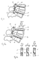
- Fig. 8a shows a second example of a stabilization device using the extruded rod 1.
- the stabilization device has at least two polyaxial bone anchoring elements 14 and 14' having a threaded shaft 15 to be anchored in the bone and a spherically-shaped head 16 at one end.
- the head 16 is pivotably held in a receiving part 17 which also receives the rod 1 in a recess.
- a pressure element (not shown) is provided which presses onto the head to fix the head in the receiving part in its angular position.
- a locking element (not shown) is also provided to fix the rod in the recess.
- the bone anchoring elements 14 and 14' are screwed into the vertebrae and thereafter the rod 1 is inserted. Since the head 16 is pivotably held in the receiving part 17 the position of the receiving parts can be adjusted relative to the heads. After adjustment of the position of the receiving parts relative to the heads and of the rod relative to the receiving part, the connection is locked by means of the locking element.
- Fig. 8b schematically shows the forces acting onto the rod under axial (A) and flexural (F) load during motion of the spinal segment shown in Fig. 8a.
- the force components of the axial and flexural load are mainly oriented in the direction of the alignment of the polymer chains 2. This renders the extruded rod particularly suitable for the application in dynamic stabilization of the spinal column. This also applies to the stabilization device shown in Fig. 7 using monoaxial screws.
- Fig. 9 and 10 show an example of a clinical application of a correction device.
- the correction device which includes two bone anchoring elements 10 and the extruded rod 1 is applied to a spinal section exhibiting scoliosis.
- the elastic rod is bent out of its neutral straight shape so as to be adapted to the curvature of the spinal deformity as shown in Fig. 9.
- a pretension is generated in the rod which urges the deformed part of the spine into a straight position as shown in Fig. 10.
- monoaxial or polyaxial screws can be used.
- Polyaxial screws have the advantage that the shaft and the head can be aligned for receiving the rod.
- Fig. 11 shows a schematic view in the direction of the longitudinal axis of the spine of one bone anchoring element anchored in a vertebra.
- the extruded rod is clamped in the receiving part 12 by the locking element 13.
- the polymer chains 2 are substantially aligned in the longitudinal direction of the rod. If required, additional fixation in the bone can be provided by means of clamps 20.
- Fig. 12 shows a modified example of a bone anchoring element with the rod inserted into the recess of the receiving part.
- the receiving part 18 comprises a recess 19 with a cross-section which differs from the cross-section of the rod.
- the cross section of the recess is oval-shaped while the cross-section of the rod is circular with a diameter smaller that that of the recess.
- Fixation can be achieved via a locking element (not shown) either directly or with a filling piece (not shown) between the locking element and the rod.
- the rod is not limited to the above described embodiments and examples of application. The features of the examples described can be combined with each other.
- the rod is shown to connect two bone anchoring elements, it can have a length sufficient to connect more than two bone anchoring elements. Since the rod is made of an elastomer, the length can be adapted before or at the time of surgery by cutting the rod.
- the rod can be made fully or partially of the polymer material. For certain applications it is sufficient that a section of the whole rod is made of extruded polymer material. The length of the section depends on the specific application and the required flexibility.
- a non isotropic shape for the cross-section such as for example a rectangular shape, can be used for providing a rod with elastic characteristics which differ dependent on the direction.
- the rod can be hollow and can include a core in its hollow interior for obtaining further characteristics.
- bone anchoring elements all known types can be used which are typically used with the known metallic rods.
- the invention is also not limited to the application for the spine.
- the rod can also be used in stabilizing a fractured bone, for example instead of a metallic rod in a fixateur adhere or interne.
- polymer material as described above means a single polymer material or mixtures of polymer materials including co-polymers and so-called block co-polymers having hard and soft segments. It also includes polymer materials with additions such as filling particles or strengthening fibres like carbon fibres or the like. Strengthening fibers can be used to enhance the stiffness, if required.
Abstract
Description
- The invention relates to a longitudinal member for use in spinal or trauma surgery and a stabilization device with such a longitudinal member.
- A dynamic stabilization system for segments of the spinal column which comprises a flexible rod made of an elastic material and bone anchors to anchor the rod in the vertebrae is known from
EP 1 364 622 A2EP 1 527 742 A1 - Usually, the elastic rods are manufactured by injection molding whereby the molten plastic material is injected at high pressure into a mold which is the inverse of the desired shape. As shown in Fig. 1, after injection molding, the
polymer chains 100 of the material are entangled and may includefilling particles 101 andtransverse links 102 between them. Arod 103 which is made by injection molding comprises an isotropic structure of the polymer chains and is therefore non homogeneous in a sense that it comprises defects in its macromolecular structure. The known elastomer rods exhibit a local flow of material when pressure is exerted onto their surface in the process of fixing the rod within a receiving part of a bone anchoring element. This local flow of material may cause a loosening of the fixation of the rod within the bone anchoring element. - It is the object of the invention to provide a longitudinal member for use in spinal or trauma surgery and a stabilization device using such a longitudinal member manufacturing which has improved mechanical properties as well as reduced manufacturing costs compared to the known polymer rods.
- The object is solved by a longitudinal member according to
claim claim 14. Further developments are given in the dependent claims. - The longitudinal member has the advantage that its tendency to flow when being fixed to the bone anchor is reduced in comparison to the known injection molded elastomer rods. In addition, the longitudinal member in form of the extruded elastomer rod exhibits a lower permanent set, which characterizes the deformation remaining after removal of the deforming stress, and a higher stiffness characterized by the e-modulus compared to the injection molded rod at identical dimensions of the rod. Therefore, under identical load conditions, an extruded elastomer rod with smaller dimensions can be used. Furthermore, the strength against mechanical tensile and/or compressive loads and the abrasion resistance is enhanced. The costs for manufacturing are reduced with regard to the necessary tools and machines which are less expensive compared to the costs for the manufacturing by injection molding.
- The rod can be cut to the desired length before or during surgery.
- Further features and advantages of the invention will become apparent and will be best understood by reference to the following detailed description of embodiments taken in conjunction with the accompanying drawings.
- Fig. 1 shows a schematic representation of an arrangement of polymer chains of a polymer plastic material after injection molding.
- Fig. 2 shows a schematic cross-section of a spinal rod made of a polymer plastic material produced by injection molding.
- Fig. 3 shows a perspective view of a rod according to the present invention.
- Fig. 4 shows a schematic cross-sectional view of the rod according to Fig. 3 in a plane including the longitudinal axis of the rod.
- Fig. 5 shows a schematic cross-sectional view of the rod according to Fig. 3 in a plane perpendicular to the longitudinal axis.
- Figs. 6a) to g) show examples of cross-sections of the rod.
- Fig. 7 shows a stabilization device for the spinal column including a rod according to the invention and two monoaxial bone screws.
- Fig. 8a shows a stabilization device for the spinal column including a rod according to the invention and two polyaxial bone screws.
- Fig. 8b schematically shows the forces acting onto the rod under axial load and flexion.
- Fig. 9 shows application of the stabilization device according to the invention to the spinal column for the purpose of correction of scoliosis, wherein the rod according to the invention is in a first, pre-stressed condition.
- Fig. 10 shows the stabilization device of Fig. 9 in a second condition.
- Fig. 11 is a schematic view showing a bone screw and a clamp anchored in a vertebra and fixing the rod.
- Fig. 12 shows a modified example of a bone anchoring element receiving the rod.
- Fig. 3 to 5 show an embodiment of the invention used as a
spinal rod 1. The rod has a substantially circular cross section and a length which is suitable to span a distance between at least two vertebrae. The diameter of the rod can be selected so as to be compatible with that of known metallic spinal rods. In this case, therod 1 can be connected to known bone screws. In the embodiment shown the cross-section of the rod is constant over the length of the rod. - The rod is made of a biocompatible plastic material which can be molded by extrusion. For example, the material can be a thermoplastic material such as polyaryletheretherketone (PEEK) Preferably, the material is flexible, such as an elastomer. Suitable elastomers are for example polymer materials on the basis of polyurethane, polycarbonate-urethane (PCU) or silicone. The rod exhibits a three-dimensional elasticity in such a way that a restoring force acts when the rod is put under load which restores the original shape of the rod.
- As can be seen in particular in Fig. 3 and 4, the macromolecular construction of the
rod 1 is characterized bypolymer chains 2 of the elastomer material which are substantially aligned in the longitudinal direction of therod 1. The macromolecular structure of the rod is therefore substantially uniform in the longitudinal direction. Thepolymer chains 2 form a fiber-like structure with the fibers oriented in the longitudinal direction, thus being load-oriented. - The
rod 1 is preferably manufactured by extrusion. In the well known manufacturing process of extrusion the solid or fluid raw material is filled in an extruder and then pressed through an opening. The parameters such as temperature and pressure during the extrusion process depend on the material used and will be recognized by those skilled in the art. - Hence, the
rod 1 can be distinguished from a conventional rod made of the same material but manufactured for example by injection molding, as shown in Fig. 2. The extruded rod has enhanced mechanical strength compared to a rod made of the same material by means of injection molding. For example, the strength against mechanical tensile and/or compressive loads is enhanced. Furthermore, the wear resistance is enhanced. Therefore, the rod implant has an improved lifetime. - The rod can have other shapes than a circular cross section. As can be seen in Figs. 6a) to g), different cross sections such as circular (Fig. 6a)), square (Fig. 6b)), rounded square (Fig. 6c)), oval-shaped (Fig. 6d)), rectangular (Fig. 6e)), rounded rectangular (Fig. 6f)) or star-shaped (Fig. 6g)) or triangular are possible. Preferably the cross-section is constant over the length of the rod. With a non-circular cross-section of the rod a rotation of the rod in the bone anchoring element to which it is connected can be prevented. In addition, the shape of the cross-section can be used to achieve bending properties in flexion/extension movement and lateral bending which can differ from each other.
- A stabilization device using the rod according to the invention comprises at least two bone anchoring elements for connection of the rod to the bone. As can be seen in Figs. 7 and 8, according to a first example the bone anchoring elements are monoaxial bone screws 10, 10' each comprising a threaded
shaft 11 which is to be anchored in a vertebra and a receivingpart 12 which is rigidly connected to the threaded shaft. The receivingpart 12 has a substantially U-shaped recess to receive therod 1. A locking element, for example an inner screw to be screwed into the recess or, as shown, anouter nut 13 is provided to fix therod 1 in the recess. The bone anchoring elements are made of a biocompatible rigid material, for example of a biocompatible metal, such as titanium or a metal alloy. - In use, first, the
bone anchoring elements 10, 10' are screwed into the vertebrae which shall be stabilized. Then therod 1 is inserted into the receivingparts 12 and, after adjustment of its position, fixed in the receiving part by means of the lockingelement 13. Due to the uniformly aligned macromolecular structure of the rod the tendency to flow under pressure of the locking element is reduced. Therefore, the risk of loosening of the fixation between the rod and the bone anchoring element is reduced. Since the rod exhibits elasticity under flexion, extension and torsion of the spinal segment, the spinal segment can be dynamically stabilized. The elasticity required for a certain application can be obtained by selecting the material and/or the size and/or the shape of the cross-section of the extruded rod. - In the stabilization device of Fig. 7 the
rod 1 is used in a straight state. The vertebral segment can perform a limited motion in all planes controlled by the elasticity of the rod. - Fig. 8a shows a second example of a stabilization device using the extruded
rod 1. The stabilization device has at least two polyaxialbone anchoring elements 14 and 14' having a threadedshaft 15 to be anchored in the bone and a spherically-shapedhead 16 at one end. Thehead 16 is pivotably held in a receivingpart 17 which also receives therod 1 in a recess. Preferably, a pressure element (not shown) is provided which presses onto the head to fix the head in the receiving part in its angular position. A locking element (not shown) is also provided to fix the rod in the recess. - In use, like in the first example, the
bone anchoring elements 14 and 14' are screwed into the vertebrae and thereafter therod 1 is inserted. Since thehead 16 is pivotably held in the receivingpart 17 the position of the receiving parts can be adjusted relative to the heads. After adjustment of the position of the receiving parts relative to the heads and of the rod relative to the receiving part, the connection is locked by means of the locking element. - Fig. 8b schematically shows the forces acting onto the rod under axial (A) and flexural (F) load during motion of the spinal segment shown in Fig. 8a. As can be seen, the force components of the axial and flexural load are mainly oriented in the direction of the alignment of the
polymer chains 2. This renders the extruded rod particularly suitable for the application in dynamic stabilization of the spinal column. This also applies to the stabilization device shown in Fig. 7 using monoaxial screws. - Fig. 9 and 10 show an example of a clinical application of a correction device. The correction device which includes two
bone anchoring elements 10 and the extrudedrod 1 is applied to a spinal section exhibiting scoliosis. The elastic rod is bent out of its neutral straight shape so as to be adapted to the curvature of the spinal deformity as shown in Fig. 9. By narrowing the distance between the screw heads of the correction device as indicated by the arrows in Fig. 9, a pretension is generated in the rod which urges the deformed part of the spine into a straight position as shown in Fig. 10. For the bone anchoring elements monoaxial or polyaxial screws can be used. Polyaxial screws have the advantage that the shaft and the head can be aligned for receiving the rod. - Fig. 11 shows a schematic view in the direction of the longitudinal axis of the spine of one bone anchoring element anchored in a vertebra. The extruded rod is clamped in the receiving
part 12 by the lockingelement 13. Thepolymer chains 2 are substantially aligned in the longitudinal direction of the rod. If required, additional fixation in the bone can be provided by means ofclamps 20. - Fig. 12 shows a modified example of a bone anchoring element with the rod inserted into the recess of the receiving part. The receiving part 18 comprises a
recess 19 with a cross-section which differs from the cross-section of the rod. In the example shown the cross section of the recess is oval-shaped while the cross-section of the rod is circular with a diameter smaller that that of the recess. Fixation can be achieved via a locking element (not shown) either directly or with a filling piece (not shown) between the locking element and the rod. - The invention is not limited to the above described embodiments and examples of application. The features of the examples described can be combined with each other. Although the rod is shown to connect two bone anchoring elements, it can have a length sufficient to connect more than two bone anchoring elements. Since the rod is made of an elastomer, the length can be adapted before or at the time of surgery by cutting the rod.
- The rod can be made fully or partially of the polymer material. For certain applications it is sufficient that a section of the whole rod is made of extruded polymer material. The length of the section depends on the specific application and the required flexibility. A non isotropic shape for the cross-section, such as for example a rectangular shape, can be used for providing a rod with elastic characteristics which differ dependent on the direction.
- The rod can be hollow and can include a core in its hollow interior for obtaining further characteristics.
- With the manufacturing method of extrusion it is possible to produce rods with different shapes and diameters of the cross-section at low costs, since it is not necessary to use complex molds and expensive machines like in the injection molding process.
- For the bone anchoring elements all known types can be used which are typically used with the known metallic rods.
- The invention is also not limited to the application for the spine. The rod can also be used in stabilizing a fractured bone, for example instead of a metallic rod in a fixateur externe or interne.
- The term polymer material as described above means a single polymer material or mixtures of polymer materials including co-polymers and so-called block co-polymers having hard and soft segments. It also includes polymer materials with additions such as filling particles or strengthening fibres like carbon fibres or the like. Strengthening fibers can be used to enhance the stiffness, if required.
Claims (17)
- A longitudinal member (1) for use in spinal or trauma surgery which is sized to span a distance between at least two vertebrae or two bone parts,
characterized in that the longitudinal member is made at least partially of an extruded polymer material. - The longitudinal member of claim 1, wherein the polymer chains (2) of the material are substantially aligned in the longitudinal direction of the member (1).
- A longitudinal member (1) for use in spinal or trauma surgery which is sized to span a distance between at least two vertebrae or two bone parts,
characterized in that the longitudinal member is made at least partially of polymer material the polymer chains (2) of which are substantially aligned in a longitudinal direction of the member and wherein the longitudinal member (1) is obtainable by extrusion. - The longitudinal member of one of claims 1 to 3, wherein the polymer material is an elastomer.
- The longitudinal member of one of claims 1 to 4, wherein said material is a polymer on the basis of polyurethane, polycarbonate-urethane (PCU) or silicone.
- The longitudinal member of one of claims 1 to 5, wherein the longitudinal member (1) is a rod.
- The longitudinal member of one of claims 1 to 6, wherein the cross-section of the member is constant over the length of the member.
- The longitudinal member of one of claims 1 to 7, wherein the member exhibits bending elasticity.
- The longitudinal member of one of claims 1 to 8, wherein the cross-section is substantially circular.
- The longitudinal member of one of claims 1 to 9, wherein the whole length of the member is made of said polymer material.
- A longitudinal member (1) for use in spinal or trauma surgery which is sized to span a distance between at least two vertebrae or two bone parts, the longitudinal member exhibiting bending and axial elasticity,
characterized in that the longitudinal member is made of load-oriented fibers and uniform cross-section. - The longitudinal member (1) of claim 11, characterized in that it is obtained by extrusion.
- The longitudinal member of claim 11 or 12, wherein the member is made of a polymer, preferable of an elastomer.
- Stabilization device for stabilizing vertebrae or bone parts, comprising
at least two bone anchoring elements having a shaft for anchoring in the bone and a receiving part for connection with a longitudinal member, characterized in that a longitudinal member according to one of claims 1 to 13 is provided for connection with the bone anchoring elements. - The stabilization device of claim 14, wherein the receiving part (12; 17; 18) comprises a recess (19) for receiving the longitudinal member, the cross-section of the part of the recess (19) receiving the longitudinal member being different from the cross section of the longitudinal member.
- Method of manufacturing a longitudinal member according to one of claims 1 to 13, characterized by the steps providing a biocompatible polymer material and
extruding it into the shape of the longitudinal member. - The method of claim 16, wherein an elastomer material, such as a polymer on the basis of polyurethane, polycarbonate-urethane (PCU) or silicone is used.
Priority Applications (9)
| Application Number | Priority Date | Filing Date | Title |
|---|---|---|---|
| DE602006016407T DE602006016407D1 (en) | 2006-05-16 | 2006-05-16 | Longitudinal part for spine or trauma surgery |
| ES06010070T ES2351157T3 (en) | 2006-05-16 | 2006-05-16 | LONGITUDINAL ELEMENT TO USE IN SPINAL OR TRAUMATOLOGICAL SURGERY. |
| EP06010070A EP1857065B1 (en) | 2006-05-16 | 2006-05-16 | Longitudinal member for use in spinal or trauma surgery |
| KR1020070045847A KR101414716B1 (en) | 2006-05-16 | 2007-05-11 | Longitudinal member for use in spinal or trauma surgery and stabilization device with such a longitudinal member |
| CN2007101029219A CN101073512B (en) | 2006-05-16 | 2007-05-11 | Longitudinal member for use in spinal or trauma surgery and stabilization device with such a longitudinal member |
| TW096116732A TWI398237B (en) | 2006-05-16 | 2007-05-11 | Longitudinal member for use in spinal or trauma surgery and stabilization device with such a longitudinal member |
| JP2007126593A JP5276799B2 (en) | 2006-05-16 | 2007-05-11 | Longitudinal material for use in spine or trauma surgery and stabilizing device comprising such a longitudinal material |
| US11/749,395 US8216274B2 (en) | 2006-05-16 | 2007-05-16 | Longitudinal member for use in spinal or trauma surgery and stabilization device with such a longitudinal member |
| US13/493,835 US20120277797A1 (en) | 2006-05-16 | 2012-06-11 | Longitudinal member for use in spinal or trauma surgery and stabilization device with such a longitudinal member |
Applications Claiming Priority (1)
| Application Number | Priority Date | Filing Date | Title |
|---|---|---|---|
| EP06010070A EP1857065B1 (en) | 2006-05-16 | 2006-05-16 | Longitudinal member for use in spinal or trauma surgery |
Publications (2)
| Publication Number | Publication Date |
|---|---|
| EP1857065A1 true EP1857065A1 (en) | 2007-11-21 |
| EP1857065B1 EP1857065B1 (en) | 2010-08-25 |
Family
ID=37198765
Family Applications (1)
| Application Number | Title | Priority Date | Filing Date |
|---|---|---|---|
| EP06010070A Not-in-force EP1857065B1 (en) | 2006-05-16 | 2006-05-16 | Longitudinal member for use in spinal or trauma surgery |
Country Status (6)
| Country | Link |
|---|---|
| US (2) | US8216274B2 (en) |
| EP (1) | EP1857065B1 (en) |
| CN (1) | CN101073512B (en) |
| DE (1) | DE602006016407D1 (en) |
| ES (1) | ES2351157T3 (en) |
| TW (1) | TWI398237B (en) |
Cited By (6)
| Publication number | Priority date | Publication date | Assignee | Title |
|---|---|---|---|---|
| EP1972289A3 (en) * | 2007-03-23 | 2009-05-13 | coLigne AG | Elongated stabilization member and bone anchor useful in bone and especially spinal repair processes |
| CH699333A1 (en) * | 2008-08-11 | 2010-02-15 | Sepitec Foundation | Connecting rod for a stabilization assembly and stabilization arrangement with at least one such connecting rod. |
| DE102010041264A1 (en) | 2010-09-23 | 2012-03-29 | Aces Gmbh | Dynamic stabilization device for the spine |
| DE102012202750A1 (en) | 2012-02-22 | 2013-08-22 | Aces Gmbh | Dynamic stabilization device for treating degenerative diseases of spinal column, has support- and mating surfaces formed for clamping by load of spring element, and retaining elements movably mounted against each other in direction |
| DE102012202749A1 (en) | 2012-02-22 | 2013-08-22 | Aces Gmbh | Dynamic stabilization device for bone e.g. spinal column, has deformable regions that are arranged in form of loop, so that sides of loop surround bone in bone quiescent state |
| EP3437576A1 (en) * | 2017-08-03 | 2019-02-06 | Biedermann Technologies GmbH & Co. KG | Stabilization device for bones or vertebrae |
Families Citing this family (74)
| Publication number | Priority date | Publication date | Assignee | Title |
|---|---|---|---|---|
| US7833250B2 (en) | 2004-11-10 | 2010-11-16 | Jackson Roger P | Polyaxial bone screw with helically wound capture connection |
| US10258382B2 (en) | 2007-01-18 | 2019-04-16 | Roger P. Jackson | Rod-cord dynamic connection assemblies with slidable bone anchor attachment members along the cord |
| US8292926B2 (en) | 2005-09-30 | 2012-10-23 | Jackson Roger P | Dynamic stabilization connecting member with elastic core and outer sleeve |
| US7862587B2 (en) | 2004-02-27 | 2011-01-04 | Jackson Roger P | Dynamic stabilization assemblies, tool set and method |
| US10729469B2 (en) | 2006-01-09 | 2020-08-04 | Roger P. Jackson | Flexible spinal stabilization assembly with spacer having off-axis core member |
| US8353932B2 (en) | 2005-09-30 | 2013-01-15 | Jackson Roger P | Polyaxial bone anchor assembly with one-piece closure, pressure insert and plastic elongate member |
| US8876868B2 (en) | 2002-09-06 | 2014-11-04 | Roger P. Jackson | Helical guide and advancement flange with radially loaded lip |
| US7621918B2 (en) | 2004-11-23 | 2009-11-24 | Jackson Roger P | Spinal fixation tool set and method |
| US7377923B2 (en) | 2003-05-22 | 2008-05-27 | Alphatec Spine, Inc. | Variable angle spinal screw assembly |
| US8092500B2 (en) | 2007-05-01 | 2012-01-10 | Jackson Roger P | Dynamic stabilization connecting member with floating core, compression spacer and over-mold |
| US7967850B2 (en) | 2003-06-18 | 2011-06-28 | Jackson Roger P | Polyaxial bone anchor with helical capture connection, insert and dual locking assembly |
| US8926670B2 (en) | 2003-06-18 | 2015-01-06 | Roger P. Jackson | Polyaxial bone screw assembly |
| US7766915B2 (en) | 2004-02-27 | 2010-08-03 | Jackson Roger P | Dynamic fixation assemblies with inner core and outer coil-like member |
| US8366753B2 (en) | 2003-06-18 | 2013-02-05 | Jackson Roger P | Polyaxial bone screw assembly with fixed retaining structure |
| US7776067B2 (en) | 2005-05-27 | 2010-08-17 | Jackson Roger P | Polyaxial bone screw with shank articulation pressure insert and method |
| US7179261B2 (en) | 2003-12-16 | 2007-02-20 | Depuy Spine, Inc. | Percutaneous access devices and bone anchor assemblies |
| US7527638B2 (en) | 2003-12-16 | 2009-05-05 | Depuy Spine, Inc. | Methods and devices for minimally invasive spinal fixation element placement |
| US11419642B2 (en) | 2003-12-16 | 2022-08-23 | Medos International Sarl | Percutaneous access devices and bone anchor assemblies |
| WO2005092218A1 (en) | 2004-02-27 | 2005-10-06 | Jackson Roger P | Orthopedic implant rod reduction tool set and method |
| US11241261B2 (en) | 2005-09-30 | 2022-02-08 | Roger P Jackson | Apparatus and method for soft spinal stabilization using a tensionable cord and releasable end structure |
| US7160300B2 (en) | 2004-02-27 | 2007-01-09 | Jackson Roger P | Orthopedic implant rod reduction tool set and method |
| US8152810B2 (en) | 2004-11-23 | 2012-04-10 | Jackson Roger P | Spinal fixation tool set and method |
| US7651502B2 (en) | 2004-09-24 | 2010-01-26 | Jackson Roger P | Spinal fixation tool set and method for rod reduction and fastener insertion |
| US8926672B2 (en) | 2004-11-10 | 2015-01-06 | Roger P. Jackson | Splay control closure for open bone anchor |
| US9393047B2 (en) | 2009-06-15 | 2016-07-19 | Roger P. Jackson | Polyaxial bone anchor with pop-on shank and friction fit retainer with low profile edge lock |
| US9980753B2 (en) | 2009-06-15 | 2018-05-29 | Roger P Jackson | pivotal anchor with snap-in-place insert having rotation blocking extensions |
| WO2006057837A1 (en) | 2004-11-23 | 2006-06-01 | Jackson Roger P | Spinal fixation tool attachment structure |
| US8444681B2 (en) | 2009-06-15 | 2013-05-21 | Roger P. Jackson | Polyaxial bone anchor with pop-on shank, friction fit retainer and winged insert |
| US8556938B2 (en) | 2009-06-15 | 2013-10-15 | Roger P. Jackson | Polyaxial bone anchor with non-pivotable retainer and pop-on shank, some with friction fit |
| US9168069B2 (en) | 2009-06-15 | 2015-10-27 | Roger P. Jackson | Polyaxial bone anchor with pop-on shank and winged insert with lower skirt for engaging a friction fit retainer |
| US9216041B2 (en) | 2009-06-15 | 2015-12-22 | Roger P. Jackson | Spinal connecting members with tensioned cords and rigid sleeves for engaging compression inserts |
| US7901437B2 (en) | 2007-01-26 | 2011-03-08 | Jackson Roger P | Dynamic stabilization member with molded connection |
| US8123749B2 (en) | 2005-03-24 | 2012-02-28 | Depuy Spine, Inc. | Low profile spinal tethering systems |
| US8105368B2 (en) | 2005-09-30 | 2012-01-31 | Jackson Roger P | Dynamic stabilization connecting member with slitted core and outer sleeve |
| GB0521582D0 (en) | 2005-10-22 | 2005-11-30 | Depuy Int Ltd | An implant for supporting a spinal column |
| GB0600662D0 (en) | 2006-01-13 | 2006-02-22 | Depuy Int Ltd | Spinal support rod kit |
| US8348952B2 (en) | 2006-01-26 | 2013-01-08 | Depuy International Ltd. | System and method for cooling a spinal correction device comprising a shape memory material for corrective spinal surgery |
| CA2670988C (en) | 2006-12-08 | 2014-03-25 | Roger P. Jackson | Tool system for dynamic spinal implants |
| US8475498B2 (en) | 2007-01-18 | 2013-07-02 | Roger P. Jackson | Dynamic stabilization connecting member with cord connection |
| US8366745B2 (en) | 2007-05-01 | 2013-02-05 | Jackson Roger P | Dynamic stabilization assembly having pre-compressed spacers with differential displacements |
| US8012177B2 (en) | 2007-02-12 | 2011-09-06 | Jackson Roger P | Dynamic stabilization assembly with frusto-conical connection |
| US10383660B2 (en) | 2007-05-01 | 2019-08-20 | Roger P. Jackson | Soft stabilization assemblies with pretensioned cords |
| CA2690038C (en) | 2007-05-31 | 2012-11-27 | Roger P. Jackson | Dynamic stabilization connecting member with pre-tensioned solid core |
| US8911477B2 (en) | 2007-10-23 | 2014-12-16 | Roger P. Jackson | Dynamic stabilization member with end plate support and cable core extension |
| GB0720762D0 (en) | 2007-10-24 | 2007-12-05 | Depuy Spine Sorl | Assembly for orthopaedic surgery |
| US9232968B2 (en) | 2007-12-19 | 2016-01-12 | DePuy Synthes Products, Inc. | Polymeric pedicle rods and methods of manufacturing |
| FR2927791B1 (en) * | 2008-02-26 | 2011-02-18 | Clariance | ARTICULAR PROSTHESIS POSTERIEURE LUMBAR WITH ROTULE |
| ES2387829T3 (en) | 2008-04-28 | 2012-10-02 | Biedermann Technologies Gmbh & Co. Kg | Element for the stabilization of the spine in the form of a rod and method for its production |
| EP2116205B1 (en) * | 2008-05-06 | 2010-12-29 | BIEDERMANN MOTECH GmbH | Rod-shaped implant, in particular for the dynamic stabilization of the spine |
| JP2012529969A (en) | 2008-08-01 | 2012-11-29 | ロジャー・ピー・ジャクソン | Longitudinal connecting member with tensioning cord with sleeve |
| US8372120B2 (en) | 2009-05-20 | 2013-02-12 | Spine Wave, Inc. | Multi-axial cross connector |
| EP2757988A4 (en) | 2009-06-15 | 2015-08-19 | Jackson Roger P | Polyaxial bone anchor with pop-on shank and winged insert with friction fit compressive collet |
| US8998959B2 (en) | 2009-06-15 | 2015-04-07 | Roger P Jackson | Polyaxial bone anchors with pop-on shank, fully constrained friction fit retainer and lock and release insert |
| US11229457B2 (en) | 2009-06-15 | 2022-01-25 | Roger P. Jackson | Pivotal bone anchor assembly with insert tool deployment |
| US9668771B2 (en) | 2009-06-15 | 2017-06-06 | Roger P Jackson | Soft stabilization assemblies with off-set connector |
| US9320543B2 (en) * | 2009-06-25 | 2016-04-26 | DePuy Synthes Products, Inc. | Posterior dynamic stabilization device having a mobile anchor |
| RU2565484C2 (en) * | 2009-07-16 | 2015-10-20 | Спайнсэйв А Г | Fixation assembly for joint bar for spine stabilisation |
| US8506603B2 (en) * | 2009-10-14 | 2013-08-13 | K2M, Inc. | Surgical rod scorer and method of use of the same |
| US9144447B2 (en) | 2009-10-14 | 2015-09-29 | K2M, Inc. | Surgical rod scorer and method of use of the same |
| US20110152937A1 (en) * | 2009-12-22 | 2011-06-23 | Warsaw Orthopedic, Inc. | Surgical Implants for Selectively Controlling Spinal Motion Segments |
| US9445844B2 (en) | 2010-03-24 | 2016-09-20 | DePuy Synthes Products, Inc. | Composite material posterior dynamic stabilization spring rod |
| JP2013540468A (en) | 2010-09-08 | 2013-11-07 | ロジャー・ピー・ジャクソン | Dynamic fixing member having an elastic part and an inelastic part |
| JP2013545527A (en) | 2010-11-02 | 2013-12-26 | ロジャー・ピー・ジャクソン | Multi-axis bone anchor with pop-on shank and pivotable retainer |
| WO2012128825A1 (en) | 2011-03-24 | 2012-09-27 | Jackson Roger P | Polyaxial bone anchor with compound articulation and pop-on shank |
| US10695097B2 (en) * | 2012-07-05 | 2020-06-30 | Spinesave Ag | Elastic rod having different degrees of stiffness for the surgical treatment of the spine |
| US8911478B2 (en) | 2012-11-21 | 2014-12-16 | Roger P. Jackson | Splay control closure for open bone anchor |
| US10058354B2 (en) | 2013-01-28 | 2018-08-28 | Roger P. Jackson | Pivotal bone anchor assembly with frictional shank head seating surfaces |
| US8852239B2 (en) | 2013-02-15 | 2014-10-07 | Roger P Jackson | Sagittal angle screw with integral shank and receiver |
| US9566092B2 (en) | 2013-10-29 | 2017-02-14 | Roger P. Jackson | Cervical bone anchor with collet retainer and outer locking sleeve |
| US9717533B2 (en) | 2013-12-12 | 2017-08-01 | Roger P. Jackson | Bone anchor closure pivot-splay control flange form guide and advancement structure |
| US9451993B2 (en) | 2014-01-09 | 2016-09-27 | Roger P. Jackson | Bi-radial pop-on cervical bone anchor |
| US10064658B2 (en) | 2014-06-04 | 2018-09-04 | Roger P. Jackson | Polyaxial bone anchor with insert guides |
| US9597119B2 (en) | 2014-06-04 | 2017-03-21 | Roger P. Jackson | Polyaxial bone anchor with polymer sleeve |
| AU2016251062B2 (en) * | 2015-04-24 | 2020-10-29 | K2M, Inc. | Tethering screw system |
Citations (1)
| Publication number | Priority date | Publication date | Assignee | Title |
|---|---|---|---|---|
| US20050033295A1 (en) | 2003-08-08 | 2005-02-10 | Paul Wisnewski | Implants formed of shape memory polymeric material for spinal fixation |
Family Cites Families (16)
| Publication number | Priority date | Publication date | Assignee | Title |
|---|---|---|---|---|
| US4653481A (en) * | 1985-07-24 | 1987-03-31 | Howland Robert S | Advanced spine fixation system and method |
| FI81498C (en) | 1987-01-13 | 1990-11-12 | Biocon Oy | SURGICAL MATERIAL OCH INSTRUMENT. |
| JP2619760B2 (en) * | 1991-12-25 | 1997-06-11 | グンゼ株式会社 | Bone treatment device and method for producing the same |
| US5545165A (en) * | 1992-10-09 | 1996-08-13 | Biedermann Motech Gmbh | Anchoring member |
| FR2697743B1 (en) * | 1992-11-09 | 1995-01-27 | Fabrication Mat Orthopedique S | Spinal osteosynthesis device applicable in particular to degenerative vertebrae. |
| EP0659062B1 (en) * | 1993-07-02 | 2009-05-27 | Synthes GmbH | Posterior vertebral column implant |
| AU6019898A (en) * | 1997-01-09 | 1998-08-03 | Cohesion Technologies, Inc. | Devices for tissue repair and methods for preparation and use thereof |
| AU2002248223A1 (en) * | 2000-12-29 | 2002-07-24 | James Thomas | Vertebral alignment system |
| US6652526B1 (en) * | 2001-10-05 | 2003-11-25 | Ruben P. Arafiles | Spinal stabilization rod fastener |
| ES2246036T3 (en) * | 2002-05-21 | 2006-02-01 | Spinelab Ag | ELASTIC SYSTEM FOR THE STABILIZATION OF THE VERTEBRAL COLUMN. |
| WO2004096066A2 (en) * | 2003-04-25 | 2004-11-11 | Kitchen Michael S | Spinal curvature correction device |
| US6986771B2 (en) * | 2003-05-23 | 2006-01-17 | Globus Medical, Inc. | Spine stabilization system |
| US20050203513A1 (en) * | 2003-09-24 | 2005-09-15 | Tae-Ahn Jahng | Spinal stabilization device |
| DE50304374D1 (en) * | 2003-10-31 | 2006-09-07 | Spinelab Ag | Locking device for pedicle screws for fixing elastic rod elements |
| US8858599B2 (en) * | 2004-06-09 | 2014-10-14 | Warsaw Orthopedic, Inc. | Systems and methods for flexible spinal stabilization |
| US7491208B2 (en) * | 2005-04-28 | 2009-02-17 | Warsaw Orthopedic, Inc. | Instrument and method for guiding surgical implants and instruments during surgery |
-
2006
- 2006-05-16 DE DE602006016407T patent/DE602006016407D1/en active Active
- 2006-05-16 ES ES06010070T patent/ES2351157T3/en active Active
- 2006-05-16 EP EP06010070A patent/EP1857065B1/en not_active Not-in-force
-
2007
- 2007-05-11 TW TW096116732A patent/TWI398237B/en not_active IP Right Cessation
- 2007-05-11 CN CN2007101029219A patent/CN101073512B/en not_active Expired - Fee Related
- 2007-05-16 US US11/749,395 patent/US8216274B2/en not_active Expired - Fee Related
-
2012
- 2012-06-11 US US13/493,835 patent/US20120277797A1/en not_active Abandoned
Patent Citations (1)
| Publication number | Priority date | Publication date | Assignee | Title |
|---|---|---|---|---|
| US20050033295A1 (en) | 2003-08-08 | 2005-02-10 | Paul Wisnewski | Implants formed of shape memory polymeric material for spinal fixation |
Cited By (10)
| Publication number | Priority date | Publication date | Assignee | Title |
|---|---|---|---|---|
| EP1972289A3 (en) * | 2007-03-23 | 2009-05-13 | coLigne AG | Elongated stabilization member and bone anchor useful in bone and especially spinal repair processes |
| US8317833B2 (en) | 2007-03-23 | 2012-11-27 | Coligne Ag | Elongated stabilization member and bone anchor useful in bone and especially spinal repair processes |
| CH699333A1 (en) * | 2008-08-11 | 2010-02-15 | Sepitec Foundation | Connecting rod for a stabilization assembly and stabilization arrangement with at least one such connecting rod. |
| EP2153784A1 (en) | 2008-08-11 | 2010-02-17 | Sepitec Foundation | Connecting rod for a spinal stabilisation assembly and spinal stabilisation assembly with at least one such connecting rod |
| DE102010041264A1 (en) | 2010-09-23 | 2012-03-29 | Aces Gmbh | Dynamic stabilization device for the spine |
| WO2012048690A1 (en) | 2010-09-23 | 2012-04-19 | Aces Gmbh | Dynamic stabilizing system for the spinal column |
| DE102012202750A1 (en) | 2012-02-22 | 2013-08-22 | Aces Gmbh | Dynamic stabilization device for treating degenerative diseases of spinal column, has support- and mating surfaces formed for clamping by load of spring element, and retaining elements movably mounted against each other in direction |
| DE102012202749A1 (en) | 2012-02-22 | 2013-08-22 | Aces Gmbh | Dynamic stabilization device for bone e.g. spinal column, has deformable regions that are arranged in form of loop, so that sides of loop surround bone in bone quiescent state |
| EP3437576A1 (en) * | 2017-08-03 | 2019-02-06 | Biedermann Technologies GmbH & Co. KG | Stabilization device for bones or vertebrae |
| US11134991B2 (en) | 2017-08-03 | 2021-10-05 | Biedermann Technologies Gmbh & Co. Kg | Stabilization device for bones or vertebrae |
Also Published As
| Publication number | Publication date |
|---|---|
| US8216274B2 (en) | 2012-07-10 |
| DE602006016407D1 (en) | 2010-10-07 |
| US20120277797A1 (en) | 2012-11-01 |
| TWI398237B (en) | 2013-06-11 |
| ES2351157T3 (en) | 2011-02-01 |
| CN101073512A (en) | 2007-11-21 |
| TW200744524A (en) | 2007-12-16 |
| US20070270843A1 (en) | 2007-11-22 |
| EP1857065B1 (en) | 2010-08-25 |
| CN101073512B (en) | 2011-02-16 |
Similar Documents
| Publication | Publication Date | Title |
|---|---|---|
| EP1857065B1 (en) | Longitudinal member for use in spinal or trauma surgery | |
| EP2160988B1 (en) | Rod-shaped implant in particular for stabilizing the spinal column and stabilization device including such a rod-shaped implant | |
| EP2116205B1 (en) | Rod-shaped implant, in particular for the dynamic stabilization of the spine | |
| US8012177B2 (en) | Dynamic stabilization assembly with frusto-conical connection | |
| EP2105101B1 (en) | Bone anchoring device | |
| US8092500B2 (en) | Dynamic stabilization connecting member with floating core, compression spacer and over-mold | |
| US20080140076A1 (en) | Dynamic stabilization connecting member with slitted segment and surrounding external elastomer | |
| KR101150539B1 (en) | Spine stabilization system | |
| US20080147122A1 (en) | Dynamic stabilization connecting member with molded inner segment and surrounding external elastomer | |
| EP1972289A2 (en) | Elongated stabilization member and bone anchor useful in bone and especially spinal repair processes | |
| CN1578644A (en) | Vibration reducing element | |
| US20100042157A1 (en) | Vertebral rod system and methods of use | |
| JP5841150B2 (en) | Spine implant set for dynamic stabilization of the spine | |
| KR101414716B1 (en) | Longitudinal member for use in spinal or trauma surgery and stabilization device with such a longitudinal member | |
| WO2009102298A1 (en) | Dynamic stabilization connecting member with slitted segment and surrounding external elastomer |
Legal Events
| Date | Code | Title | Description |
|---|---|---|---|
| PUAI | Public reference made under article 153(3) epc to a published international application that has entered the european phase |
Free format text: ORIGINAL CODE: 0009012 |
|
| AK | Designated contracting states |
Kind code of ref document: A1 Designated state(s): AT BE BG CH CY CZ DE DK EE ES FI FR GB GR HU IE IS IT LI LT LU LV MC NL PL PT RO SE SI SK TR |
|
| AX | Request for extension of the european patent |
Extension state: AL BA HR MK YU |
|
| 17P | Request for examination filed |
Effective date: 20080514 |
|
| 17Q | First examination report despatched |
Effective date: 20080616 |
|
| AKX | Designation fees paid |
Designated state(s): CH DE ES FR GB IT LI |
|
| GRAP | Despatch of communication of intention to grant a patent |
Free format text: ORIGINAL CODE: EPIDOSNIGR1 |
|
| GRAS | Grant fee paid |
Free format text: ORIGINAL CODE: EPIDOSNIGR3 |
|
| GRAA | (expected) grant |
Free format text: ORIGINAL CODE: 0009210 |
|
| AK | Designated contracting states |
Kind code of ref document: B1 Designated state(s): CH DE ES FR GB IT LI |
|
| REG | Reference to a national code |
Ref country code: GB Ref legal event code: FG4D |
|
| REG | Reference to a national code |
Ref country code: CH Ref legal event code: EP |
|
| REF | Corresponds to: |
Ref document number: 602006016407 Country of ref document: DE Date of ref document: 20101007 Kind code of ref document: P |
|
| REG | Reference to a national code |
Ref country code: CH Ref legal event code: NV Representative=s name: NOVAGRAAF INTERNATIONAL SA |
|
| REG | Reference to a national code |
Ref country code: ES Ref legal event code: FG2A Effective date: 20110120 |
|
| REG | Reference to a national code |
Ref country code: CH Ref legal event code: PFA Owner name: BIEDERMANN MOTECH GMBH Free format text: BIEDERMANN MOTECH GMBH#BERTHA-VON-SUTTNER-STRASSE 23#78054 VS-SCHWENNINGEN (DE) -TRANSFER TO- BIEDERMANN MOTECH GMBH#BERTHA-VON-SUTTNER-STRASSE 23#78054 VS-SCHWENNINGEN (DE) |
|
| PLBE | No opposition filed within time limit |
Free format text: ORIGINAL CODE: 0009261 |
|
| STAA | Information on the status of an ep patent application or granted ep patent |
Free format text: STATUS: NO OPPOSITION FILED WITHIN TIME LIMIT |
|
| 26N | No opposition filed |
Effective date: 20110526 |
|
| REG | Reference to a national code |
Ref country code: DE Ref legal event code: R097 Ref document number: 602006016407 Country of ref document: DE Effective date: 20110526 |
|
| REG | Reference to a national code |
Ref country code: DE Ref legal event code: R082 Ref document number: 602006016407 Country of ref document: DE Representative=s name: PRUEFER & PARTNER GBR, DE |
|
| REG | Reference to a national code |
Ref country code: DE Ref legal event code: R082 Ref document number: 602006016407 Country of ref document: DE Representative=s name: PRUEFER & PARTNER GBR, DE Effective date: 20121128 Ref country code: DE Ref legal event code: R081 Ref document number: 602006016407 Country of ref document: DE Owner name: BIEDERMANN TECHNOLOGIES GMBH & CO. KG, DE Free format text: FORMER OWNER: BIEDERMANN MOTECH GMBH, 78054 VILLINGEN-SCHWENNINGEN, DE Effective date: 20121128 Ref country code: DE Ref legal event code: R082 Ref document number: 602006016407 Country of ref document: DE Representative=s name: PRUEFER & PARTNER MBB PATENTANWAELTE RECHTSANW, DE Effective date: 20121128 |
|
| REG | Reference to a national code |
Ref country code: CH Ref legal event code: PUE Owner name: BIEDERMANN TECHNOLOGIES GMBH AND CO. KG, DE Free format text: FORMER OWNER: BIEDERMANN MOTECH GMBH AND CO. KG, DE Ref country code: CH Ref legal event code: PFA Owner name: BIEDERMANN MOTECH GMBH AND CO. KG, DE Free format text: FORMER OWNER: BIEDERMANN MOTECH GMBH, DE |
|
| REG | Reference to a national code |
Ref country code: CH Ref legal event code: PFA Owner name: BIEDERMANN MOTECH GMBH AND CO. KG, DE Free format text: FORMER OWNER: BIEDERMANN MOTECH GMBH, DE Ref country code: ES Ref legal event code: PC2A Owner name: BIEDERMANN MOTECH GMBH & CO.KG. Effective date: 20130205 Ref country code: CH Ref legal event code: PUE Owner name: BIEDERMANN TECHNOLOGIES GMBH AND CO. KG, DE Free format text: FORMER OWNER: BIEDERMANN MOTECH GMBH AND CO. KG, DE |
|
| REG | Reference to a national code |
Ref country code: ES Ref legal event code: PC2A Owner name: BIEDERMANN TECHNOLOGIES GMBH & CO. KG Effective date: 20130311 |
|
| REG | Reference to a national code |
Ref country code: GB Ref legal event code: 732E Free format text: REGISTERED BETWEEN 20130307 AND 20130313 |
|
| REG | Reference to a national code |
Ref country code: FR Ref legal event code: TP Owner name: BIEDERMANN TECHNOLOGIES GMBH & CO.KG, DE Effective date: 20130329 Ref country code: FR Ref legal event code: CD Owner name: BIEDERMANN TECHNOLOGIES GMBH & CO.KG, DE Effective date: 20130329 |
|
| REG | Reference to a national code |
Ref country code: FR Ref legal event code: PLFP Year of fee payment: 10 |
|
| PGFP | Annual fee paid to national office [announced via postgrant information from national office to epo] |
Ref country code: CH Payment date: 20150520 Year of fee payment: 10 Ref country code: GB Payment date: 20150521 Year of fee payment: 10 Ref country code: ES Payment date: 20150520 Year of fee payment: 10 Ref country code: DE Payment date: 20150527 Year of fee payment: 10 |
|
| PGFP | Annual fee paid to national office [announced via postgrant information from national office to epo] |
Ref country code: IT Payment date: 20150528 Year of fee payment: 10 Ref country code: FR Payment date: 20150528 Year of fee payment: 10 |
|
| REG | Reference to a national code |
Ref country code: DE Ref legal event code: R119 Ref document number: 602006016407 Country of ref document: DE |
|
| REG | Reference to a national code |
Ref country code: CH Ref legal event code: PL |
|
| GBPC | Gb: european patent ceased through non-payment of renewal fee |
Effective date: 20160516 |
|
| PG25 | Lapsed in a contracting state [announced via postgrant information from national office to epo] |
Ref country code: CH Free format text: LAPSE BECAUSE OF NON-PAYMENT OF DUE FEES Effective date: 20160531 Ref country code: LI Free format text: LAPSE BECAUSE OF NON-PAYMENT OF DUE FEES Effective date: 20160531 |
|
| PG25 | Lapsed in a contracting state [announced via postgrant information from national office to epo] |
Ref country code: IT Free format text: LAPSE BECAUSE OF NON-PAYMENT OF DUE FEES Effective date: 20160516 |
|
| REG | Reference to a national code |
Ref country code: FR Ref legal event code: ST Effective date: 20170131 |
|
| PG25 | Lapsed in a contracting state [announced via postgrant information from national office to epo] |
Ref country code: DE Free format text: LAPSE BECAUSE OF NON-PAYMENT OF DUE FEES Effective date: 20161201 Ref country code: FR Free format text: LAPSE BECAUSE OF NON-PAYMENT OF DUE FEES Effective date: 20160531 |
|
| PG25 | Lapsed in a contracting state [announced via postgrant information from national office to epo] |
Ref country code: GB Free format text: LAPSE BECAUSE OF NON-PAYMENT OF DUE FEES Effective date: 20160516 |
|
| PG25 | Lapsed in a contracting state [announced via postgrant information from national office to epo] |
Ref country code: ES Free format text: LAPSE BECAUSE OF NON-PAYMENT OF DUE FEES Effective date: 20160517 |
|
| REG | Reference to a national code |
Ref country code: ES Ref legal event code: FD2A Effective date: 20181205 |