EP1743601A1 - Intraocular lens system - Google Patents
Intraocular lens system Download PDFInfo
- Publication number
- EP1743601A1 EP1743601A1 EP06116307A EP06116307A EP1743601A1 EP 1743601 A1 EP1743601 A1 EP 1743601A1 EP 06116307 A EP06116307 A EP 06116307A EP 06116307 A EP06116307 A EP 06116307A EP 1743601 A1 EP1743601 A1 EP 1743601A1
- Authority
- EP
- European Patent Office
- Prior art keywords
- component
- rubber
- lens system
- lens
- lip
- Prior art date
- Legal status (The legal status is an assumption and is not a legal conclusion. Google has not performed a legal analysis and makes no representation as to the accuracy of the status listed.)
- Granted
Links
Images


Classifications
-
- A—HUMAN NECESSITIES
- A61—MEDICAL OR VETERINARY SCIENCE; HYGIENE
- A61F—FILTERS IMPLANTABLE INTO BLOOD VESSELS; PROSTHESES; DEVICES PROVIDING PATENCY TO, OR PREVENTING COLLAPSING OF, TUBULAR STRUCTURES OF THE BODY, e.g. STENTS; ORTHOPAEDIC, NURSING OR CONTRACEPTIVE DEVICES; FOMENTATION; TREATMENT OR PROTECTION OF EYES OR EARS; BANDAGES, DRESSINGS OR ABSORBENT PADS; FIRST-AID KITS
- A61F2/00—Filters implantable into blood vessels; Prostheses, i.e. artificial substitutes or replacements for parts of the body; Appliances for connecting them with the body; Devices providing patency to, or preventing collapsing of, tubular structures of the body, e.g. stents
- A61F2/02—Prostheses implantable into the body
- A61F2/14—Eye parts, e.g. lenses, corneal implants; Implanting instruments specially adapted therefor; Artificial eyes
- A61F2/16—Intraocular lenses
- A61F2/1694—Capsular bag spreaders therefor
-
- A—HUMAN NECESSITIES
- A61—MEDICAL OR VETERINARY SCIENCE; HYGIENE
- A61F—FILTERS IMPLANTABLE INTO BLOOD VESSELS; PROSTHESES; DEVICES PROVIDING PATENCY TO, OR PREVENTING COLLAPSING OF, TUBULAR STRUCTURES OF THE BODY, e.g. STENTS; ORTHOPAEDIC, NURSING OR CONTRACEPTIVE DEVICES; FOMENTATION; TREATMENT OR PROTECTION OF EYES OR EARS; BANDAGES, DRESSINGS OR ABSORBENT PADS; FIRST-AID KITS
- A61F2/00—Filters implantable into blood vessels; Prostheses, i.e. artificial substitutes or replacements for parts of the body; Appliances for connecting them with the body; Devices providing patency to, or preventing collapsing of, tubular structures of the body, e.g. stents
- A61F2/02—Prostheses implantable into the body
- A61F2/14—Eye parts, e.g. lenses, corneal implants; Implanting instruments specially adapted therefor; Artificial eyes
- A61F2/16—Intraocular lenses
- A61F2/1613—Intraocular lenses having special lens configurations, e.g. multipart lenses; having particular optical properties, e.g. pseudo-accommodative lenses, lenses having aberration corrections, diffractive lenses, lenses for variably absorbing electromagnetic radiation, lenses having variable focus
- A61F2/1624—Intraocular lenses having special lens configurations, e.g. multipart lenses; having particular optical properties, e.g. pseudo-accommodative lenses, lenses having aberration corrections, diffractive lenses, lenses for variably absorbing electromagnetic radiation, lenses having variable focus having adjustable focus; power activated variable focus means, e.g. mechanically or electrically by the ciliary muscle or from the outside
- A61F2/1629—Intraocular lenses having special lens configurations, e.g. multipart lenses; having particular optical properties, e.g. pseudo-accommodative lenses, lenses having aberration corrections, diffractive lenses, lenses for variably absorbing electromagnetic radiation, lenses having variable focus having adjustable focus; power activated variable focus means, e.g. mechanically or electrically by the ciliary muscle or from the outside for changing longitudinal position, i.e. along the visual axis when implanted
-
- A—HUMAN NECESSITIES
- A61—MEDICAL OR VETERINARY SCIENCE; HYGIENE
- A61F—FILTERS IMPLANTABLE INTO BLOOD VESSELS; PROSTHESES; DEVICES PROVIDING PATENCY TO, OR PREVENTING COLLAPSING OF, TUBULAR STRUCTURES OF THE BODY, e.g. STENTS; ORTHOPAEDIC, NURSING OR CONTRACEPTIVE DEVICES; FOMENTATION; TREATMENT OR PROTECTION OF EYES OR EARS; BANDAGES, DRESSINGS OR ABSORBENT PADS; FIRST-AID KITS
- A61F2/00—Filters implantable into blood vessels; Prostheses, i.e. artificial substitutes or replacements for parts of the body; Appliances for connecting them with the body; Devices providing patency to, or preventing collapsing of, tubular structures of the body, e.g. stents
- A61F2/02—Prostheses implantable into the body
- A61F2/14—Eye parts, e.g. lenses, corneal implants; Implanting instruments specially adapted therefor; Artificial eyes
- A61F2/16—Intraocular lenses
- A61F2/1613—Intraocular lenses having special lens configurations, e.g. multipart lenses; having particular optical properties, e.g. pseudo-accommodative lenses, lenses having aberration corrections, diffractive lenses, lenses for variably absorbing electromagnetic radiation, lenses having variable focus
- A61F2/1648—Multipart lenses
Definitions
- This invention relates generally to the field of intraocular lenses (IOL) and, more particularly, to multi-lens, micro-incision IOLs.
- the human eye in its simplest terms functions to provide vision by transmitting light through a clear outer portion called the cornea, and focusing the image by way of a crystalline lens onto a retina.
- the quality of the focused image depends on many factors including the size and shape of the eye, and the transparency of the cornea and the lens.
- IOL intraocular lens
- phacoemulsification In the United States, the majority of cataractous lenses are removed by a surgical technique called phacoemulsification. During this procedure, an opening is made in the anterior capsule and a thin phacoemulsification cutting tip is inserted into the diseased lens and vibrated ultrasonically. The vibrating cutting tip liquifies or emulsifies the lens so that the lens may be aspirated out of the eye. The diseased lens, once removed, is replaced by an artificial lens.
- the IOL Prior to the present invention, when a cataract or other disease required the removal of the natural lens and replacement with an artificial IOL, the IOL was a monofocal lens. Most IOLs are sold in power increments of +/- 0.5 diopters, and the ultimate power of the lens depends upon where the lens sits along the optical axis. The fixed increment of the lens, and the slight variation in lens placement can result in less than optimum vision. Although this situation occurs relatively infrequently, and generally is not severe, some patients ultimately are required to use a pair of spectacles or contact lenses for optimum vision. If the power of the implanted lens is incorrect, removal and exchange of a new lens is difficult because of fibrosis of the lens haptics within the capsular bag.
- U.S. Patent Nos. 5,628,798 and 5,800,533 disclose a threadedly adjustable IOL wherein the location of the optic along the visual axis may be adjusted.
- an IOL having haptics with frangible stiffeners. Once implanted in an eye, the stiffeners are selectively cut or heated above their t g by laser radiation, causing the stiffness of the haptic to change and adjusting the location of the lens within the capsule bag.
- the multi-lens designs and the threadedly adjustable designs are not optimized for the reduction or elimination of posterior capsule opacification (PCO).
- PCO posterior capsule opacification
- many of these lenses are not capable of being implanted through a vary small (less than 2 millimeters) incision.
- the present invention improves upon the prior art by providing a two or three component lens system.
- the first component is a ring-like supporting component that is implanted in the capsular bag following cataract surgery.
- the first component is a non-optical component and does not correct for any refractive errors.
- the first component may contain features to help reduce or eliminate PCO.
- the second component is an optical component that may contain all of the corrective optical power of the lens system.
- the second component has a pair of tabs for locking the second component within the first component.
- the first component includes a feature that allows the surgeon to change the position of the second component along the optical axis of the lens system.
- the third component is optional and is similar to second component and contains some optical power to correct for any residual optical error not corrected by the second component.
- the second and third components may also be implanted so as to move relative to one another, thereby providing some accommodation.
- one objective of the present invention is to provide a safe and biocompatible intraocular lens.
- Another objective of the present invention is to provide a safe and biocompatible intraocular lens that is easily implanted in the posterior chamber.
- Still another objective of the present invention is to provide a safe and biocompatible intraocular lens that is stable in the posterior chamber.
- Still another objective of the present invention is to provide a safe and biocompatible adjustable lens system.
- Still another objective of the present invention is to provide a safe and biocompatible lens system that can be implanted through a small incision.
- Still another objective of the present invention is to provide a safe and biocompatible lens system that helps reduce the incidence of PCO.
- Still another objective of the present invention is to provide a safe and biocompatible lens system for use in cataract and/or clear lens exchange surgeries.
- lens system 10 of the present invention generally includes a first, or base, component 12, second, or optical, component 14 and may optionally includes third, or secondary optical component 16.
- First component 12 is generally ring-like, and, as best seen in FIG. 3, is generally "I"-shaped in cross section. This "I"-shape forms circumferential anterior channel 19 and posterior channel 18 within the inner diameter of component 12.
- Such a construction is easy to mold, and provides the flexibility necessary to allow component 12 to be inserted into an eye through a sub-2 millimeter incision.
- Component 12 is constructed with sharp, square outer edges 11 to help prevent PCO.
- Component 12 is preferably formed in any suitable overall diameter, for example, between approximately 8.0 millimeters and 12.0 millimeters, a suitable interior diameter, for example, between approximately 6.0 millimeters and 8.5 millimeters and made from a soft, foldable material such as a soft acrylic.
- component 12 may be made from a material that is stiffer relative to optical component 14 or less stiff relative to optical component 14.
- component 12 may be made of rubber elastomers, such as butyl rubber, latex rubber, natural rubber, pure gum rubber, neoprene rubber, acrylonitrile rubber, styrene-butadiene rubber, ethylene-propylene diene monomer rubber, acrylonitrile-butadiene-styrene (ABS) rubber, epichlorohydrin rubber, hypalon rubber, silicone rubber and siloxane elastomers, such as poly(dimethylsiloxane), polyurethane rubber, viton rubber, ethylene-butylene rubber, isobutylene rubber and elastomers of polyphosphazenes, like poly(bis-trifluorethoxyphosphazene) oly(dimethylphosphazene) and poly(phenylmethylphosphazene).
- rubber elastomers such as butyl rubber, latex rubber, natural rubber, pure gum rubber, neoprene rubber,
- base component 12 may be formed so as to be opaque, such as by frosting or texturing the anterior and/or posterior surfaces of base component 12, or base component may be relatively clear.
- Base component 12 may also contain a chromophore to block ultraviolet and/or blue and/or green light, such chromophore(s) being well-known in the art.
- second component 14 is generally circular with an optic 15 having a diameter for example, between approximately 4.0 millimeters and 7.0 millimeters.
- Optic 15 tapers from being relatively thick in the middle to having a relatively thin, or sharp, edge that connects to a plurality of haptics 24 integrally formed with optic 15 so as to give optical component 14 overall length of between approximately 8.0 millimeters and 10.0 millimeters and preferably, is made from a soft, foldable material such as a soft acrylic.
- Second component 14 may also contain a chromophore to block ultraviolet and/or blue light, such chromophore(s) being well-known in the art, but unlike base component 12, second component 14 is optically clear.
- Haptics 24 are connected to optic 15 by connecting portions 26 that are relatively wide in plan view, but relatively thin in cross-section.
- haptics 24 contain outwardly projecting tips 32.
- Connecting portions 26 may also contain positioning or manipulation holes 30.
- third component 16 is generally circular with an optic 34 having a diameter for example, between approximately 4.0 millimeters and 7.0 millimeters.
- Third component 16 contains a plurality of haptics 36 integrally formed with optic 34 so as to give third component 16 overall length of between approximately 8.0 millimeters and 10.0 millimeters and preferably, is made from a soft, foldable material such as a soft acrylic.
- Third component 16 may also contain a chromophore to block ultraviolet and/or blue light, such chromophore(s) being well-known in the art, but unlike base component 12, lens component 16 is optically clear.
- Haptics 36 are connected to optic 34 by connecting portions 38 that are relatively wide in plan view, but relatively thin in cross-section.
- haptics 36 contain outwardly projecting tips 40.
- Such a construction helps to prevent rotation of third component 16 within second component 12 and helps to maintain the stability of third component 16 in the plane perpendicular to optical axis 28, but allows some flexibility along optical axis 28.
- third component 16 is of similar construction as second component 14 except, as best seen in FIGS. 6 and 8, third component 16 has less optical power than second component 14 and therefore, is generally thinner than second component 14.
- Either second component 14 or third component 16 may be constructed to correct any of a variety of possible refractive errors, such a astigmatism (toric), presbyopia (accommodative, pseudo-accommodative or multifocal) or customized to correct higher order aberrations, such refractive errors and optical corrections therefore being well-known in the art.
- refractive errors such as a astigmatism (toric), presbyopia (accommodative, pseudo-accommodative or multifocal) or customized to correct higher order aberrations, such refractive errors and optical corrections therefore being well-known in the art.
- lens system 10 is assembled by placing tips 32 or 40 of second component 14 or third component 16, respectively, into posterior channel 18 of first component 12, thereby compressing connecting portions 26 and 38 respectively and allowing both haptic 24 and 36 to snap within channel 18.
- Third component 16 maybe installed in a similar manner to correct any residual refractive errors not corrected by second component 14.
- third component 16 is rotated approximately 90° relative to second component 14.
- first or base component 12' has an inner rim or lip 150 that is slightly elliptical, oval, out-of-round or non-circular in shape having a short axis 100 and a long axis 102.
- This slightly oval or otherwise out of round shape will vary the amount of compression on haptics 24 of second component 14.
- Rotation of second component 14 so that haptics 14 are be aligned along short axis 100 will cause haptics 14 to more compressed than rotation of second component 14 so that haptics 14 are be aligned along long axis 102, thereby changing the position of 15 along optical axis 28 and correspondingly varying the effective refractive power of lens system 10 implanted in an eye.
- inner rim or lip 200 of first or base component 12" contains a plurality of cam ridges 201, 202 and 203 or varying step height.
- Rotation of second component 14 within base component 12" causes haptics 24 to ride along on ridges 201, 202 or 203, thereby varying the location of optic 15 along optical axis 28 and correspondingly changing the effective refractive power of lens system 10 implanted in an eye.
Abstract

Description
- This invention relates generally to the field of intraocular lenses (IOL) and, more particularly, to multi-lens, micro-incision IOLs.
- The human eye in its simplest terms functions to provide vision by transmitting light through a clear outer portion called the cornea, and focusing the image by way of a crystalline lens onto a retina. The quality of the focused image depends on many factors including the size and shape of the eye, and the transparency of the cornea and the lens.
- When age or disease causes the lens to become less transparent, vision deteriorates because of the diminished light which can be transmitted to the retina. This deficiency in the lens of the eye is medically known as a cataract. An accepted treatment for this condition is surgical removal of the lens and replacement of the lens function by an artificial intraocular lens (IOL).
- In the United States, the majority of cataractous lenses are removed by a surgical technique called phacoemulsification. During this procedure, an opening is made in the anterior capsule and a thin phacoemulsification cutting tip is inserted into the diseased lens and vibrated ultrasonically. The vibrating cutting tip liquifies or emulsifies the lens so that the lens may be aspirated out of the eye. The diseased lens, once removed, is replaced by an artificial lens.
- Prior to the present invention, when a cataract or other disease required the removal of the natural lens and replacement with an artificial IOL, the IOL was a monofocal lens. Most IOLs are sold in power increments of +/- 0.5 diopters, and the ultimate power of the lens depends upon where the lens sits along the optical axis. The fixed increment of the lens, and the slight variation in lens placement can result in less than optimum vision. Although this situation occurs relatively infrequently, and generally is not severe, some patients ultimately are required to use a pair of spectacles or contact lenses for optimum vision. If the power of the implanted lens is incorrect, removal and exchange of a new lens is difficult because of fibrosis of the lens haptics within the capsular bag.
- There have been several prior suggested adjustable power IOLs, none of which have been commercially introduced. For example,
U.S. Patent Nos. 5,222,981 (Werblin ) and5,358,520 (Patel ),
suggest the use of a second or even a third optic that may be implanted and attached to a previously implanted primary optic so as to adjust the overall optic power of the multi-lens system.U.S. Patent Nos. 5,628,798 and5,800,533 (Eggleston, et al. ),
disclose a threadedly adjustable IOL wherein the location of the optic along the visual axis may be adjusted.U.S. Patent No. 4,575,373 (Johnson ), the entire contents of which being incorporated herein by reference, discloses an IOL having an optic and an outer ring and connections between the optic and the outer ring made from a heat-shrinkable plastic. The connections are heated with a laser to adjust the power of the IOL.U.S. Patent Nos. 4,919,151 and5,026,783 (Grubbs, et al. )
disclose a lens made from a polymer that swells or otherwise changes shape- The lens is implanted or injected into the capsule bag and selectively polymerized so as to adjust the power of the optic.U.S. Patent No. 5,571,177 (Deacon, et al. ),
discloses an IOL having haptics with frangible stiffeners. Once implanted in an eye, the stiffeners are selectively cut or heated above their tg by laser radiation, causing the stiffness of the haptic to change and adjusting the location of the lens within the capsule bag. The multi-lens designs and the threadedly adjustable designs are not optimized for the reduction or elimination of posterior capsule opacification (PCO). In addition, many of these lenses are not capable of being implanted through a vary small (less than 2 millimeters) incision. - Therefore, a need continues to exist for a safe and stable intraocular lens system that provides adjustment of lens power. Such a lens system could be used in cataract or clear lens exchange surgeries.
- The present invention improves upon the prior art by providing a two or three component lens system. The first component is a ring-like supporting component that is implanted in the capsular bag following cataract surgery. The first component is a non-optical component and does not correct for any refractive errors. The first component may contain features to help reduce or eliminate PCO. The second component is an optical component that may contain all of the corrective optical power of the lens system. The second component has a pair of tabs for locking the second component within the first component. The first component includes a feature that allows the surgeon to change the position of the second component along the optical axis of the lens system. The third component is optional and is similar to second component and contains some optical power to correct for any residual optical error not corrected by the second component. The second and third components may also be implanted so as to move relative to one another, thereby providing some accommodation.
- Accordingly, one objective of the present invention is to provide a safe and biocompatible intraocular lens.
- Another objective of the present invention is to provide a safe and biocompatible intraocular lens that is easily implanted in the posterior chamber.
- Still another objective of the present invention is to provide a safe and biocompatible intraocular lens that is stable in the posterior chamber.
- Still another objective of the present invention is to provide a safe and biocompatible adjustable lens system.
- Still another objective of the present invention is to provide a safe and biocompatible lens system that can be implanted through a small incision.
- Still another objective of the present invention is to provide a safe and biocompatible lens system that helps reduce the incidence of PCO.
- Still another objective of the present invention is to provide a safe and biocompatible lens system for use in cataract and/or clear lens exchange surgeries.
- These and other advantages and objectives of the present invention will become apparent from the detailed description and claims that follow.
-
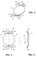
- FIG. 1 is an enlarged perspective view of the first component of the lens system of the present system.
- FIG. 2 is an enlarged plan view of a first embodiment of the first component of the lens system of the present system.
- FIG. 3 is an enlarged cross-sectional view of the first component of the lens system of the present system taken at line 3-3 in FIG. 2.
- FIG. 4 is an enlarged perspective view of the second component of the lens system of the present system.
- FIG. 5 is an enlarged plan view of the second component of the lens system of the present system.
- FIG. 6 is an enlarged cross-sectional view of the first component of the lens system of the present system taken at line 6-6 in FIG. 5.
- FIG. 7 is an enlarged plan view of the third component of the lens system of the present system.
- FIG. 8 is an enlarged cross-sectional view of the third component of the lens system of the present system taken at line 8-8 in FIG. 7.
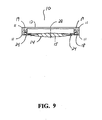
- FIG. 9 is an enlarged cross-sectional view of the lens system of the present system with the second component installed within the first component.
- FIG. 10 is an enlarged plan view of a second embodiment of the first component of the lens system of the present system.
- FIG. 11 is an enlarged cross-sectional view of a third embodiment of the first component of the lens system of the present system.
- As best seen in FIGS. 1, 4 and 7,
lens system 10 of the present invention generally includes a first, or base,component 12, second, or optical,component 14 and may optionally includes third, or secondaryoptical component 16.First component 12 is generally ring-like, and, as best seen in FIG. 3, is generally "I"-shaped in cross section. This "I"-shape forms circumferentialanterior channel 19 andposterior channel 18 within the inner diameter ofcomponent 12. Such a construction is easy to mold, and provides the flexibility necessary to allowcomponent 12 to be inserted into an eye through a sub-2 millimeter incision.Component 12 is constructed with sharp, square outer edges 11 to help prevent PCO.Component 12 is preferably formed in any suitable overall diameter, for example, between approximately 8.0 millimeters and 12.0 millimeters, a suitable interior diameter, for example, between approximately 6.0 millimeters and 8.5 millimeters and made from a soft, foldable material such as a soft acrylic. Alternatively,component 12 may be made from a material that is stiffer relative tooptical component 14 or less stiff relative tooptical component 14. By way of example,component 12 may be made of rubber elastomers, such as butyl rubber, latex rubber, natural rubber, pure gum rubber, neoprene rubber, acrylonitrile rubber, styrene-butadiene rubber, ethylene-propylene diene monomer rubber, acrylonitrile-butadiene-styrene (ABS) rubber, epichlorohydrin rubber, hypalon rubber, silicone rubber and siloxane elastomers, such as poly(dimethylsiloxane), polyurethane rubber, viton rubber, ethylene-butylene rubber, isobutylene rubber and elastomers of polyphosphazenes, like poly(bis-trifluorethoxyphosphazene) oly(dimethylphosphazene) and poly(phenylmethylphosphazene). Preferably,base component 12 may be formed so as to be opaque, such as by frosting or texturing the anterior and/or posterior surfaces ofbase component 12, or base component may be relatively clear.Base component 12 may also contain a chromophore to block ultraviolet and/or blue and/or green light, such chromophore(s) being well-known in the art. - As best seen in FIGS. 4-6,
second component 14 is generally circular with an optic 15 having a diameter for example, between approximately 4.0 millimeters and 7.0 millimeters.Optic 15 tapers from being relatively thick in the middle to having a relatively thin, or sharp, edge that connects to a plurality ofhaptics 24 integrally formed withoptic 15 so as to giveoptical component 14 overall length of between approximately 8.0 millimeters and 10.0 millimeters and preferably, is made from a soft, foldable material such as a soft acrylic.Second component 14 may also contain a chromophore to block ultraviolet and/or blue light, such chromophore(s) being well-known in the art, but unlikebase component 12,second component 14 is optically clear.Haptics 24 are connected tooptic 15 by connectingportions 26 that are relatively wide in plan view, but relatively thin in cross-section. In addition, haptics 24 contain outwardly projectingtips 32. Such a construction helps to prevent rotation ofsecond component 14 withinfirst component 12 and helps to maintain the stability ofoptical portion 14 in the plane perpendicular tooptical axis 28, but allows some flexibility alongoptical axis 28. Connectingportions 26 may also contain positioning or manipulation holes 30. - As best seen in FIGS. 7-8,
third component 16 is generally circular with an optic 34 having a diameter for example, between approximately 4.0 millimeters and 7.0 millimeters.Third component 16 contains a plurality ofhaptics 36 integrally formed withoptic 34 so as to givethird component 16 overall length of between approximately 8.0 millimeters and 10.0 millimeters and preferably, is made from a soft, foldable material such as a soft acrylic.Third component 16 may also contain a chromophore to block ultraviolet and/or blue light, such chromophore(s) being well-known in the art, but unlikebase component 12,lens component 16 is optically clear.Haptics 36 are connected tooptic 34 by connectingportions 38 that are relatively wide in plan view, but relatively thin in cross-section. In addition, haptics 36 contain outwardly projectingtips 40. Such a construction helps to prevent rotation ofthird component 16 withinsecond component 12 and helps to maintain the stability ofthird component 16 in the plane perpendicular tooptical axis 28, but allows some flexibility alongoptical axis 28. In general,third component 16 is of similar construction assecond component 14 except, as best seen in FIGS. 6 and 8,third component 16 has less optical power thansecond component 14 and therefore, is generally thinner thansecond component 14. Eithersecond component 14 orthird component 16 may be constructed to correct any of a variety of possible refractive errors, such a astigmatism (toric), presbyopia (accommodative, pseudo-accommodative or multifocal) or customized to correct higher order aberrations, such refractive errors and optical corrections therefore being well-known in the art. - As best seen in FIG. 9,
lens system 10 is assembled by placingtips second component 14 orthird component 16, respectively, intoposterior channel 18 offirst component 12, thereby compressing connectingportions channel 18.Third component 16 maybe installed in a similar manner to correct any residual refractive errors not corrected bysecond component 14. Preferably,third component 16 is rotated approximately 90° relative tosecond component 14. - As best seen in FIG. 10, in a second embodiment of the present invention, first or base component 12' has an inner rim or
lip 150 that is slightly elliptical, oval, out-of-round or non-circular in shape having ashort axis 100 and along axis 102. This slightly oval or otherwise out of round shape will vary the amount of compression on haptics 24 ofsecond component 14. Rotation ofsecond component 14 so thathaptics 14 are be aligned alongshort axis 100 will causehaptics 14 to more compressed than rotation ofsecond component 14 so thathaptics 14 are be aligned alonglong axis 102, thereby changing the position of 15 alongoptical axis 28 and correspondingly varying the effective refractive power oflens system 10 implanted in an eye. - As best seen in FIG. 11, in a third embodiment of the present invention, inner rim or lip 200 of first or
base component 12" contains a plurality ofcam ridges second component 14 withinbase component 12" causes haptics 24 to ride along onridges optic 15 alongoptical axis 28 and correspondingly changing the effective refractive power oflens system 10 implanted in an eye. - This description is given for purposes of illustration and explanation. It will be apparent to those skilled in the relevant art that changes and modifications may be made to the invention described above without departing from its scope
Claims (11)
- An intraocular lens system (10), comprising:a) a ring-like first component (12, 12',12") having an inner rim or lip (150, 200), the inner rim or lip (150) having a non-circular shape in plan view with a short axis (100) and a long axis (102), or the inner rim or lip (200) having a plurality of cam ridges (210,202,203) of varying step height; andb) a second component (14) having an optical power, the second component having a plurality of haptics (24) sized to ride on the inner rim or lip of the first component, or on the cam ridges on the inner rim or lip, so that rotation of the second component causes the second component to move along the optical axis (28) of the lens system.
- The lens system of claim 1, wherein the first component (12, 12', 12") is opaque.
- The lens system of claim 1, wherein the first component (12, 12', 12") is stiff relative to the second component (14).
- The lens system of claim 1, wherein the first component (12, 12', 12") is made from a rubber elastomer.
- The lens system of claim 4, wherein the rubber elastomer is selected from; butyl rubber, latex rubber, natural rubber, pure gum rubber, neoprene rubber, acrylonitrile rubber, styrene-butadiene rubber, ethylene-propylene diene monomer rubber, acrylonitrile-butadiene-styrene (ABS) rubber, epichlorohydrin rubber, hypalon rubber, silicone rubber and siloxane elastomers including poly(dimethylsiloxane), polyurethane rubber, viton rubber, ethylene-butylene rubber, isobutylene rubber and elastomers of polyphosphazenes including poly(bis-trifluorethoxyphosphazene), poly(dimethylphosphazene) or poly(phenylmethylphosphazene).
- The lens system of claim 1, wherein the second component (14) contains a chromophore to block ultraviolet and/or blue and/or green light.
- The lens system of claim 1, wherein the first component (12, 12', 12") is made of a soft acrylic.
- The lens system of any one of claims 1 to 7, further comprising a third component (16) constructed to correct astigmatism or presbyopia.
- The lens system of any one of claims 1 to 7, further comprising a third component (16) customized to correct higher order aberrations.
- The lens system of any one of claims 1 to 7, wherein the second component (14) is constructed to correct astigmatism.
- The lens system of any one of claims 1 to 7, wherein the second component (14) is customized to correct higher order aberrations.
Priority Applications (3)
| Application Number | Priority Date | Filing Date | Title |
|---|---|---|---|
| SI200630195T SI1743601T1 (en) | 2005-07-11 | 2006-06-29 | Intraocular lens system |
| PL06116307T PL1743601T3 (en) | 2005-07-11 | 2006-06-29 | Intraocular lens system |
| CY20091100086T CY1109598T1 (en) | 2005-07-11 | 2009-01-23 | INTRODUCTION LENS SYSTEM |
Applications Claiming Priority (1)
| Application Number | Priority Date | Filing Date | Title |
|---|---|---|---|
| US11/178,758 US20070010881A1 (en) | 2005-07-11 | 2005-07-11 | Intraocular lens system |
Publications (2)
| Publication Number | Publication Date |
|---|---|
| EP1743601A1 true EP1743601A1 (en) | 2007-01-17 |
| EP1743601B1 EP1743601B1 (en) | 2008-11-05 |
Family
ID=36940254
Family Applications (1)
| Application Number | Title | Priority Date | Filing Date |
|---|---|---|---|
| EP06116307A Active EP1743601B1 (en) | 2005-07-11 | 2006-06-29 | Intraocular lens system |
Country Status (13)
| Country | Link |
|---|---|
| US (2) | US20070010881A1 (en) |
| EP (1) | EP1743601B1 (en) |
| JP (1) | JP4624967B2 (en) |
| AT (1) | ATE413150T1 (en) |
| AU (1) | AU2006202919B9 (en) |
| CA (1) | CA2550977C (en) |
| CY (1) | CY1109598T1 (en) |
| DE (1) | DE602006003480D1 (en) |
| DK (1) | DK1743601T3 (en) |
| ES (1) | ES2316006T3 (en) |
| PL (1) | PL1743601T3 (en) |
| PT (1) | PT1743601E (en) |
| SI (1) | SI1743601T1 (en) |
Cited By (13)
| Publication number | Priority date | Publication date | Assignee | Title |
|---|---|---|---|---|
| EP2129331A1 (en) * | 2007-01-29 | 2009-12-09 | Werblin Research & Development Corp. | Intraocular lens system |
| WO2010125596A1 (en) * | 2009-04-30 | 2010-11-04 | Promacon Italia Oftalmologia S.R.L. | Intraocular lens with system of laser adjustable haptics |
| WO2013158942A1 (en) * | 2012-04-20 | 2013-10-24 | Hanita Lenses R.C.A. Ltd. | Intraocular assembly |
| US10561493B2 (en) | 2015-04-03 | 2020-02-18 | The Regents Of The University Of Colorado, A Body Corporate | Lens capsule tension devices |
| US10736735B2 (en) | 2015-04-03 | 2020-08-11 | The Regents Of The University Of Colorado, A Body Corporate | Devices and methods for stabilization of an ocular lens capsule and preventing artificial intraocular lens implant rotation post cataract surgery |
| EP3782584A1 (en) * | 2013-06-03 | 2021-02-24 | Alcon Inc. | Modular intraocular lens designs and methods |
| US11045309B2 (en) | 2016-05-05 | 2021-06-29 | The Regents Of The University Of Colorado | Intraocular lens designs for improved stability |
| US11076948B2 (en) | 2015-11-04 | 2021-08-03 | Alcon Inc. | Modular intraocular lens designs, tools and methods |
| US11382736B2 (en) | 2017-06-27 | 2022-07-12 | Alcon Inc. | Injector, intraocular lens system, and related methods |
| EP4029474A1 (en) * | 2014-06-19 | 2022-07-20 | Omega Ophthalmics LLC | Prosthetic capsular devices |
| US11406491B2 (en) | 2015-01-30 | 2022-08-09 | Alcon Inc | Modular intraocular lens designs, tools and methods |
| US11406490B2 (en) | 2012-01-24 | 2022-08-09 | Alcon Inc. | Modular intraocular lens designs and methods |
| US11446138B2 (en) | 2014-02-18 | 2022-09-20 | Alcon Inc. | Modular intraocular lens designs, tools and methods |
Families Citing this family (34)
| Publication number | Priority date | Publication date | Assignee | Title |
|---|---|---|---|---|
| US8177762B2 (en) | 1998-12-07 | 2012-05-15 | C. R. Bard, Inc. | Septum including at least one identifiable feature, access ports including same, and related methods |
| IL161706A0 (en) | 2004-04-29 | 2004-09-27 | Nulens Ltd | Intraocular lens fixation device |
| US9474888B2 (en) | 2005-03-04 | 2016-10-25 | C. R. Bard, Inc. | Implantable access port including a sandwiched radiopaque insert |
| US8202259B2 (en) | 2005-03-04 | 2012-06-19 | C. R. Bard, Inc. | Systems and methods for identifying an access port |
| EP1858565B1 (en) | 2005-03-04 | 2021-08-11 | C.R. Bard, Inc. | Access port identification systems and methods |
| US7947022B2 (en) | 2005-03-04 | 2011-05-24 | C. R. Bard, Inc. | Access port identification systems and methods |
| US8029482B2 (en) | 2005-03-04 | 2011-10-04 | C. R. Bard, Inc. | Systems and methods for radiographically identifying an access port |
| CA2601351A1 (en) | 2005-03-30 | 2006-10-05 | Nulens Ltd | Accommodating intraocular lens (aiol) assemblies, and discrete components therfor |
| US10307581B2 (en) | 2005-04-27 | 2019-06-04 | C. R. Bard, Inc. | Reinforced septum for an implantable medical device |
| EP2324878B1 (en) | 2005-04-27 | 2014-08-20 | C.R. Bard, Inc. | Infusion apparatuses provided with septum |
| EP1874393B1 (en) | 2005-04-27 | 2017-09-06 | C.R.Bard, Inc. | Infusion apparatuses |
| US20120179249A1 (en) * | 2005-07-21 | 2012-07-12 | Cornell University | Accommodating intraocular lens and methods of use |
| JP2008110625A (en) * | 2006-10-27 | 2008-05-15 | Toyo Tire & Rubber Co Ltd | Pneumatic tire |
| US9265912B2 (en) | 2006-11-08 | 2016-02-23 | C. R. Bard, Inc. | Indicia informative of characteristics of insertable medical devices |
| US9642986B2 (en) | 2006-11-08 | 2017-05-09 | C. R. Bard, Inc. | Resource information key for an insertable medical device |
| KR100843454B1 (en) * | 2007-03-08 | 2008-07-03 | 박경진 | Supporter for intraocular lens |
| US20090088842A1 (en) * | 2007-09-27 | 2009-04-02 | Drew Morgan | Intraocular Lens |
| US9579496B2 (en) | 2007-11-07 | 2017-02-28 | C. R. Bard, Inc. | Radiopaque and septum-based indicators for a multi-lumen implantable port |
| US11890443B2 (en) | 2008-11-13 | 2024-02-06 | C. R. Bard, Inc. | Implantable medical devices including septum-based indicators |
| US8932271B2 (en) | 2008-11-13 | 2015-01-13 | C. R. Bard, Inc. | Implantable medical devices including septum-based indicators |
| ES2695907T3 (en) | 2009-11-17 | 2019-01-11 | Bard Inc C R | Overmolded access port that includes anchoring and identification features |
| USD682416S1 (en) | 2010-12-30 | 2013-05-14 | C. R. Bard, Inc. | Implantable access port |
| USD676955S1 (en) | 2010-12-30 | 2013-02-26 | C. R. Bard, Inc. | Implantable access port |
| WO2012106673A1 (en) | 2011-02-04 | 2012-08-09 | Forsight Labs, Llc | Intraocular accommodating lens |
| RU2531472C1 (en) * | 2013-08-02 | 2014-10-20 | федеральное государственное бюджетное учреждение "Межотраслевой научно-технический комплекс "Микрохирургия глаза" имени академика С.Н. Федорова" Министерства здравоохранения Российской Федерации | Artificial intraocular lens |
| JP6591525B2 (en) | 2014-03-28 | 2019-10-16 | フォーサイト・ラブス・リミテッド・ライアビリティ・カンパニーForSight Labs, LLC | Perspective accommodation type intraocular lens |
| US11938018B2 (en) | 2014-09-22 | 2024-03-26 | Onpoint Vision, Inc. | Intraocular pseudophakic contact lens (IOPCL) for treating age-related macular degeneration (AMD) or other eye disorders |
| US11109957B2 (en) | 2014-09-22 | 2021-09-07 | Onpoint Vision, Inc. | Intraocular pseudophakic contact lens with mechanism for securing by anterior leaflet of capsular wall and related system and method |
| US10945832B2 (en) | 2014-09-22 | 2021-03-16 | Onpoint Vision, Inc. | Intraocular pseudophakic contact lens with mechanism for securing by anterior leaflet of capsular wall and related system and method |
| US10159562B2 (en) | 2014-09-22 | 2018-12-25 | Kevin J. Cady | Intraocular pseudophakic contact lenses and related systems and methods |
| US10299910B2 (en) | 2014-09-22 | 2019-05-28 | Kevin J. Cady | Intraocular pseudophakic contact lens with mechanism for securing by anterior leaflet of capsular wall and related system and method |
| WO2018081595A1 (en) * | 2016-10-28 | 2018-05-03 | Forsight Vision6, Inc. | Accommodating intraocular lens and methods of implantation |
| DE102019134386A1 (en) | 2019-12-13 | 2021-06-17 | Carl Zeiss Meditec Ag | Intraocular lens |
| US11759309B2 (en) | 2020-04-29 | 2023-09-19 | Long Bridge Medical, Inc. | Devices to support and position an intraocular lens within the eye and methods of use |
Citations (8)
| Publication number | Priority date | Publication date | Assignee | Title |
|---|---|---|---|---|
| US5713958A (en) * | 1995-06-22 | 1998-02-03 | W.K. Et Associes | Intraocular implant device for correcting ocular anisotropy |
| US5824074A (en) * | 1994-02-03 | 1998-10-20 | Koch; Hans-Reinhard | Intraoccular lens arrangement and method for correcting astigmatism |
| EP0941717A1 (en) * | 1996-01-22 | 1999-09-15 | Robert Anello | Adjustable intraocular lens |
| DE10059482A1 (en) * | 2000-11-30 | 2002-06-06 | Acritec Gmbh | Tensioning ring for capsule of artificial lens, comprising step around inner surface for safe positioning of haptics |
| US6616691B1 (en) * | 2003-01-10 | 2003-09-09 | Alcon, Inc. | Accommodative intraocular lens |
| US20040024454A1 (en) * | 2002-07-30 | 2004-02-05 | Peter Toop | Intraocular lens |
| US20050015145A1 (en) * | 2003-07-14 | 2005-01-20 | Tran Son Trung | Intraocular lens system |
| US20060069432A1 (en) * | 2004-09-30 | 2006-03-30 | Tran Son T | Intraocular lens system |
Family Cites Families (26)
| Publication number | Priority date | Publication date | Assignee | Title |
|---|---|---|---|---|
| US4073014A (en) * | 1976-05-28 | 1978-02-14 | Stanley Poler | Intra-ocular lens |
| US4122556A (en) * | 1977-03-23 | 1978-10-31 | Stanley Poler | Intra-ocular lens |
| US4575373A (en) * | 1984-11-02 | 1986-03-11 | Johnson Don R | Laser adjustable intraocular lens and method of altering lens power |
| US4661108A (en) * | 1985-07-03 | 1987-04-28 | Surgidev Corporation | Intraocular lens |
| US4919151A (en) * | 1987-07-06 | 1990-04-24 | California Institute Of Technology | Synthetic polymer for endocapsular lens replacement |
| US5026783A (en) * | 1988-10-24 | 1991-06-25 | California Institute Of Technology | High energy polymers formed by ring opening metathesis polymerization |
| US5358520A (en) * | 1989-04-28 | 1994-10-25 | Nestle S.A. | Supplementary intraocular lens system |
| US5480426A (en) * | 1989-12-26 | 1996-01-02 | Chu; Milton W. | Method of implanting an intraocular lens having haptics for scleral fixation |
| US5222981A (en) * | 1991-08-15 | 1993-06-29 | Werblin Research & Development Corp. | Multi-component intraocular lens |
| US5288293A (en) * | 1992-09-24 | 1994-02-22 | Donnell Jr Francis E O | In vivo modification of refractive power of an intraocular lens implant |
| US5571177A (en) * | 1993-06-14 | 1996-11-05 | Allergan | IOL structured for post-operative re-positioning and method for post-operative IOL re-positioning |
| US5628795A (en) * | 1995-03-15 | 1997-05-13 | Langerman David W | Spare parts for use in ophthalmic surgical procedures |
| US5984962A (en) * | 1996-01-22 | 1999-11-16 | Quantum Vision, Inc. | Adjustable intraocular lens |
| US5800533A (en) * | 1996-03-18 | 1998-09-01 | Harry C. Eggleston | Adjustable intraocular lens implant with magnetic adjustment facilities |
| US5628798A (en) * | 1996-03-18 | 1997-05-13 | Harry C. Eggleston | Adjustable and removable intraocular lens implant |
| US5922821A (en) * | 1996-08-09 | 1999-07-13 | Alcon Laboratories, Inc. | Ophthalmic lens polymers |
| US5769889A (en) * | 1996-09-05 | 1998-06-23 | Kelman; Charles D. | High myopia anterior chamber lens with anti-glare mask |
| US6015842A (en) * | 1997-08-07 | 2000-01-18 | Alcon Laboratories, Inc. | Method of preparing foldable hydrophilic ophthalmic device materials |
| US20030158560A1 (en) * | 1999-03-22 | 2003-08-21 | Valdemar Portney | Corrective intraocular lens system, intraocular lenses, and lens handling and installation devices for use therewith, and installation method |
| US6406494B1 (en) * | 1999-04-30 | 2002-06-18 | Allergan Sales, Inc. | Moveable intraocular lens |
| US6797004B1 (en) * | 2000-03-02 | 2004-09-28 | Advanced Medical Optics, Inc. | Holders for intraocular lenses |
| US6464725B2 (en) * | 2001-01-23 | 2002-10-15 | Bernt Christian Skotton | Two-lens adjustable intraocular lens system |
| WO2002060346A2 (en) * | 2001-02-01 | 2002-08-08 | Tekia, Inc. | Two part 'l'- or 's'-shaped phakic iol |
| US6558419B1 (en) * | 2001-11-08 | 2003-05-06 | Bausch & Lomb Incorporated | Intraocular lens |
| US20030187504A1 (en) * | 2002-04-01 | 2003-10-02 | Weinschenk Joseph I. | Adjustable intraocular lens |
| US20040059414A1 (en) * | 2002-09-25 | 2004-03-25 | Green George F. | Intraocular lens |
-
2005
- 2005-07-11 US US11/178,758 patent/US20070010881A1/en not_active Abandoned
-
2006
- 2006-06-27 CA CA2550977A patent/CA2550977C/en not_active Expired - Fee Related
- 2006-06-29 SI SI200630195T patent/SI1743601T1/en unknown
- 2006-06-29 DK DK06116307T patent/DK1743601T3/en active
- 2006-06-29 ES ES06116307T patent/ES2316006T3/en active Active
- 2006-06-29 PL PL06116307T patent/PL1743601T3/en unknown
- 2006-06-29 DE DE602006003480T patent/DE602006003480D1/en active Active
- 2006-06-29 AT AT06116307T patent/ATE413150T1/en active
- 2006-06-29 EP EP06116307A patent/EP1743601B1/en active Active
- 2006-06-29 PT PT06116307T patent/PT1743601E/en unknown
- 2006-07-06 AU AU2006202919A patent/AU2006202919B9/en not_active Ceased
- 2006-07-10 JP JP2006189888A patent/JP4624967B2/en active Active
-
2009
- 2009-01-23 CY CY20091100086T patent/CY1109598T1/en unknown
- 2009-04-27 US US12/430,618 patent/US20100030331A1/en not_active Abandoned
Patent Citations (8)
| Publication number | Priority date | Publication date | Assignee | Title |
|---|---|---|---|---|
| US5824074A (en) * | 1994-02-03 | 1998-10-20 | Koch; Hans-Reinhard | Intraoccular lens arrangement and method for correcting astigmatism |
| US5713958A (en) * | 1995-06-22 | 1998-02-03 | W.K. Et Associes | Intraocular implant device for correcting ocular anisotropy |
| EP0941717A1 (en) * | 1996-01-22 | 1999-09-15 | Robert Anello | Adjustable intraocular lens |
| DE10059482A1 (en) * | 2000-11-30 | 2002-06-06 | Acritec Gmbh | Tensioning ring for capsule of artificial lens, comprising step around inner surface for safe positioning of haptics |
| US20040024454A1 (en) * | 2002-07-30 | 2004-02-05 | Peter Toop | Intraocular lens |
| US6616691B1 (en) * | 2003-01-10 | 2003-09-09 | Alcon, Inc. | Accommodative intraocular lens |
| US20050015145A1 (en) * | 2003-07-14 | 2005-01-20 | Tran Son Trung | Intraocular lens system |
| US20060069432A1 (en) * | 2004-09-30 | 2006-03-30 | Tran Son T | Intraocular lens system |
Cited By (15)
| Publication number | Priority date | Publication date | Assignee | Title |
|---|---|---|---|---|
| EP2129331A4 (en) * | 2007-01-29 | 2012-04-04 | Werblin Res & Dev Corp | Intraocular lens system |
| EP2129331A1 (en) * | 2007-01-29 | 2009-12-09 | Werblin Research & Development Corp. | Intraocular lens system |
| WO2010125596A1 (en) * | 2009-04-30 | 2010-11-04 | Promacon Italia Oftalmologia S.R.L. | Intraocular lens with system of laser adjustable haptics |
| US11406490B2 (en) | 2012-01-24 | 2022-08-09 | Alcon Inc. | Modular intraocular lens designs and methods |
| WO2013158942A1 (en) * | 2012-04-20 | 2013-10-24 | Hanita Lenses R.C.A. Ltd. | Intraocular assembly |
| US9757227B2 (en) | 2012-04-20 | 2017-09-12 | Hanita Lenses | Intraocular assembly |
| EP3782584A1 (en) * | 2013-06-03 | 2021-02-24 | Alcon Inc. | Modular intraocular lens designs and methods |
| US11446138B2 (en) | 2014-02-18 | 2022-09-20 | Alcon Inc. | Modular intraocular lens designs, tools and methods |
| EP4029474A1 (en) * | 2014-06-19 | 2022-07-20 | Omega Ophthalmics LLC | Prosthetic capsular devices |
| US11406491B2 (en) | 2015-01-30 | 2022-08-09 | Alcon Inc | Modular intraocular lens designs, tools and methods |
| US10736735B2 (en) | 2015-04-03 | 2020-08-11 | The Regents Of The University Of Colorado, A Body Corporate | Devices and methods for stabilization of an ocular lens capsule and preventing artificial intraocular lens implant rotation post cataract surgery |
| US10561493B2 (en) | 2015-04-03 | 2020-02-18 | The Regents Of The University Of Colorado, A Body Corporate | Lens capsule tension devices |
| US11076948B2 (en) | 2015-11-04 | 2021-08-03 | Alcon Inc. | Modular intraocular lens designs, tools and methods |
| US11045309B2 (en) | 2016-05-05 | 2021-06-29 | The Regents Of The University Of Colorado | Intraocular lens designs for improved stability |
| US11382736B2 (en) | 2017-06-27 | 2022-07-12 | Alcon Inc. | Injector, intraocular lens system, and related methods |
Also Published As
| Publication number | Publication date |
|---|---|
| JP2007021209A (en) | 2007-02-01 |
| SI1743601T1 (en) | 2009-04-30 |
| JP4624967B2 (en) | 2011-02-02 |
| EP1743601B1 (en) | 2008-11-05 |
| US20070010881A1 (en) | 2007-01-11 |
| AU2006202919B2 (en) | 2009-11-19 |
| CA2550977C (en) | 2010-11-02 |
| DE602006003480D1 (en) | 2008-12-18 |
| ES2316006T3 (en) | 2009-04-01 |
| AU2006202919A1 (en) | 2007-01-25 |
| CA2550977A1 (en) | 2007-01-11 |
| PT1743601E (en) | 2008-12-22 |
| DK1743601T3 (en) | 2008-12-15 |
| CY1109598T1 (en) | 2014-08-13 |
| US20100030331A1 (en) | 2010-02-04 |
| AU2006202919B9 (en) | 2009-12-17 |
| PL1743601T3 (en) | 2009-04-30 |
| ATE413150T1 (en) | 2008-11-15 |
Similar Documents
| Publication | Publication Date | Title |
|---|---|---|
| EP1743601B1 (en) | Intraocular lens system | |
| CA2580331C (en) | Intraocular lens system | |
| US6972034B2 (en) | Intraocular lens system | |
| EP1933768B1 (en) | Accomodative intraocular lens system | |
| US7223288B2 (en) | Accommodative intraocular lens | |
| AU2003270082B2 (en) | Accommodative intraocular lens | |
| EP1499264A1 (en) | Accommodative intraocular lens |
Legal Events
| Date | Code | Title | Description |
|---|---|---|---|
| PUAI | Public reference made under article 153(3) epc to a published international application that has entered the european phase |
Free format text: ORIGINAL CODE: 0009012 |
|
| AK | Designated contracting states |
Kind code of ref document: A1 Designated state(s): AT BE BG CH CY CZ DE DK EE ES FI FR GB GR HU IE IS IT LI LT LU LV MC NL PL PT RO SE SI SK TR |
|
| AX | Request for extension of the european patent |
Extension state: AL BA HR MK YU |
|
| 17P | Request for examination filed |
Effective date: 20070213 |
|
| 17Q | First examination report despatched |
Effective date: 20070315 |
|
| AKX | Designation fees paid |
Designated state(s): AT BE BG CH CY CZ DE DK EE ES FI FR GB GR HU IE IS IT LI LT LU LV MC NL PL PT RO SE SI SK TR |
|
| GRAP | Despatch of communication of intention to grant a patent |
Free format text: ORIGINAL CODE: EPIDOSNIGR1 |
|
| GRAS | Grant fee paid |
Free format text: ORIGINAL CODE: EPIDOSNIGR3 |
|
| GRAA | (expected) grant |
Free format text: ORIGINAL CODE: 0009210 |
|
| AK | Designated contracting states |
Kind code of ref document: B1 Designated state(s): AT BE BG CH CY CZ DE DK EE ES FI FR GB GR HU IE IS IT LI LT LU LV MC NL PL PT RO SE SI SK TR |
|
| REG | Reference to a national code |
Ref country code: GB Ref legal event code: FG4D |
|
| REG | Reference to a national code |
Ref country code: CH Ref legal event code: EP |
|
| REG | Reference to a national code |
Ref country code: IE Ref legal event code: FG4D |
|
| REG | Reference to a national code |
Ref country code: DK Ref legal event code: T3 |
|
| REF | Corresponds to: |
Ref document number: 602006003480 Country of ref document: DE Date of ref document: 20081218 Kind code of ref document: P |
|
| REG | Reference to a national code |
Ref country code: PT Ref legal event code: SC4A Free format text: AVAILABILITY OF NATIONAL TRANSLATION Effective date: 20081210 |
|
| REG | Reference to a national code |
Ref country code: RO Ref legal event code: EPE |
|
| REG | Reference to a national code |
Ref country code: SE Ref legal event code: TRGR |
|
| REG | Reference to a national code |
Ref country code: CH Ref legal event code: NV Representative=s name: LEMAN CONSULTING S.A. |
|
| REG | Reference to a national code |
Ref country code: GR Ref legal event code: EP Ref document number: 20090400162 Country of ref document: GR |
|
| REG | Reference to a national code |
Ref country code: ES Ref legal event code: FG2A Ref document number: 2316006 Country of ref document: ES Kind code of ref document: T3 |
|
| REG | Reference to a national code |
Ref country code: EE Ref legal event code: FG4A Ref document number: E002832 Country of ref document: EE Effective date: 20090112 |
|
| REG | Reference to a national code |
Ref country code: PL Ref legal event code: T3 |
|
| REG | Reference to a national code |
Ref country code: HU Ref legal event code: AG4A Ref document number: E004810 Country of ref document: HU |
|
| RAP2 | Party data changed (patent owner data changed or rights of a patent transferred) |
Owner name: ALCON, INC. |
|
| PLBE | No opposition filed within time limit |
Free format text: ORIGINAL CODE: 0009261 |
|
| STAA | Information on the status of an ep patent application or granted ep patent |
Free format text: STATUS: NO OPPOSITION FILED WITHIN TIME LIMIT |
|
| NLT2 | Nl: modifications (of names), taken from the european patent patent bulletin |
Owner name: ALCON, INC. Effective date: 20090805 |
|
| 26N | No opposition filed |
Effective date: 20090806 |
|
| PGFP | Annual fee paid to national office [announced via postgrant information from national office to epo] |
Ref country code: CY Payment date: 20100618 Year of fee payment: 5 |
|
| PGFP | Annual fee paid to national office [announced via postgrant information from national office to epo] |
Ref country code: CZ Payment date: 20110620 Year of fee payment: 6 Ref country code: MC Payment date: 20110603 Year of fee payment: 6 Ref country code: SE Payment date: 20110629 Year of fee payment: 6 Ref country code: GR Payment date: 20110629 Year of fee payment: 6 Ref country code: LT Payment date: 20110601 Year of fee payment: 6 Ref country code: PT Payment date: 20110602 Year of fee payment: 6 Ref country code: IS Payment date: 20110601 Year of fee payment: 6 Ref country code: LV Payment date: 20110607 Year of fee payment: 6 |
|
| PGFP | Annual fee paid to national office [announced via postgrant information from national office to epo] |
Ref country code: HU Payment date: 20110609 Year of fee payment: 6 Ref country code: SI Payment date: 20110622 Year of fee payment: 6 Ref country code: RO Payment date: 20110606 Year of fee payment: 6 Ref country code: LU Payment date: 20110706 Year of fee payment: 6 Ref country code: SK Payment date: 20110603 Year of fee payment: 6 Ref country code: DK Payment date: 20110627 Year of fee payment: 6 Ref country code: BG Payment date: 20110624 Year of fee payment: 6 Ref country code: EE Payment date: 20110606 Year of fee payment: 6 Ref country code: FI Payment date: 20110629 Year of fee payment: 6 Ref country code: AT Payment date: 20110602 Year of fee payment: 6 |
|
| PGFP | Annual fee paid to national office [announced via postgrant information from national office to epo] |
Ref country code: BE Payment date: 20110627 Year of fee payment: 6 |
|
| BERE | Be: lapsed |
Owner name: ALCON, INC. Effective date: 20120630 |
|
| REG | Reference to a national code |
Ref country code: PT Ref legal event code: MM4A Free format text: LAPSE DUE TO NON-PAYMENT OF FEES Effective date: 20130102 |
|
| REG | Reference to a national code |
Ref country code: DK Ref legal event code: EBP |
|
| REG | Reference to a national code |
Ref country code: SE Ref legal event code: EUG |
|
| PG25 | Lapsed in a contracting state [announced via postgrant information from national office to epo] |
Ref country code: CZ Free format text: LAPSE BECAUSE OF NON-PAYMENT OF DUE FEES Effective date: 20120629 Ref country code: CY Free format text: LAPSE BECAUSE OF NON-PAYMENT OF DUE FEES Effective date: 20120629 Ref country code: IS Free format text: LAPSE BECAUSE OF FAILURE TO SUBMIT A TRANSLATION OF THE DESCRIPTION OR TO PAY THE FEE WITHIN THE PRESCRIBED TIME-LIMIT Effective date: 20121231 Ref country code: MC Free format text: LAPSE BECAUSE OF NON-PAYMENT OF DUE FEES Effective date: 20120630 Ref country code: FI Free format text: LAPSE BECAUSE OF NON-PAYMENT OF DUE FEES Effective date: 20120629 |
|
| REG | Reference to a national code |
Ref country code: AT Ref legal event code: MM01 Ref document number: 413150 Country of ref document: AT Kind code of ref document: T Effective date: 20120629 Ref country code: EE Ref legal event code: MM4A Ref document number: E002832 Country of ref document: EE Effective date: 20120630 |
|
| REG | Reference to a national code |
Ref country code: LT Ref legal event code: MM4D Effective date: 20120629 |
|
| PG25 | Lapsed in a contracting state [announced via postgrant information from national office to epo] |
Ref country code: SE Free format text: LAPSE BECAUSE OF NON-PAYMENT OF DUE FEES Effective date: 20120630 Ref country code: LV Free format text: LAPSE BECAUSE OF NON-PAYMENT OF DUE FEES Effective date: 20120629 |
|
| REG | Reference to a national code |
Ref country code: SK Ref legal event code: MM4A Ref document number: E 4887 Country of ref document: SK Effective date: 20120629 Ref country code: GR Ref legal event code: ML Ref document number: 20090400162 Country of ref document: GR Effective date: 20130104 |
|
| REG | Reference to a national code |
Ref country code: SI Ref legal event code: KO00 Effective date: 20130205 |
|
| PG25 | Lapsed in a contracting state [announced via postgrant information from national office to epo] |
Ref country code: BE Free format text: LAPSE BECAUSE OF NON-PAYMENT OF DUE FEES Effective date: 20120630 Ref country code: LT Free format text: LAPSE BECAUSE OF NON-PAYMENT OF DUE FEES Effective date: 20120629 Ref country code: EE Free format text: LAPSE BECAUSE OF NON-PAYMENT OF DUE FEES Effective date: 20120630 Ref country code: HU Free format text: LAPSE BECAUSE OF NON-PAYMENT OF DUE FEES Effective date: 20120630 |
|
| PG25 | Lapsed in a contracting state [announced via postgrant information from national office to epo] |
Ref country code: PT Free format text: LAPSE BECAUSE OF NON-PAYMENT OF DUE FEES Effective date: 20130102 Ref country code: SK Free format text: LAPSE BECAUSE OF NON-PAYMENT OF DUE FEES Effective date: 20120629 Ref country code: SI Free format text: LAPSE BECAUSE OF NON-PAYMENT OF DUE FEES Effective date: 20120630 Ref country code: GR Free format text: LAPSE BECAUSE OF NON-PAYMENT OF DUE FEES Effective date: 20130104 |
|
| PG25 | Lapsed in a contracting state [announced via postgrant information from national office to epo] |
Ref country code: AT Free format text: LAPSE BECAUSE OF NON-PAYMENT OF DUE FEES Effective date: 20120629 |
|
| PG25 | Lapsed in a contracting state [announced via postgrant information from national office to epo] |
Ref country code: DK Free format text: LAPSE BECAUSE OF NON-PAYMENT OF DUE FEES Effective date: 20120702 |
|
| PG25 | Lapsed in a contracting state [announced via postgrant information from national office to epo] |
Ref country code: RO Free format text: LAPSE BECAUSE OF NON-PAYMENT OF DUE FEES Effective date: 20120629 |
|
| PG25 | Lapsed in a contracting state [announced via postgrant information from national office to epo] |
Ref country code: LU Free format text: LAPSE BECAUSE OF NON-PAYMENT OF DUE FEES Effective date: 20120629 |
|
| PG25 | Lapsed in a contracting state [announced via postgrant information from national office to epo] |
Ref country code: BG Free format text: LAPSE BECAUSE OF NON-PAYMENT OF DUE FEES Effective date: 20120630 |
|
| REG | Reference to a national code |
Ref country code: FR Ref legal event code: PLFP Year of fee payment: 11 |
|
| REG | Reference to a national code |
Ref country code: FR Ref legal event code: PLFP Year of fee payment: 12 |
|
| REG | Reference to a national code |
Ref country code: CH Ref legal event code: NV Representative=s name: IP PARTNERS J. WENGER, CH |
|
| REG | Reference to a national code |
Ref country code: FR Ref legal event code: PLFP Year of fee payment: 13 |
|
| PGFP | Annual fee paid to national office [announced via postgrant information from national office to epo] |
Ref country code: ES Payment date: 20190619 Year of fee payment: 19 Ref country code: IT Payment date: 20190620 Year of fee payment: 14 Ref country code: PL Payment date: 20190531 Year of fee payment: 14 Ref country code: NL Payment date: 20190612 Year of fee payment: 14 |
|
| PGFP | Annual fee paid to national office [announced via postgrant information from national office to epo] |
Ref country code: TR Payment date: 20190621 Year of fee payment: 14 |
|
| PGFP | Annual fee paid to national office [announced via postgrant information from national office to epo] |
Ref country code: CH Payment date: 20190614 Year of fee payment: 14 |
|
| REG | Reference to a national code |
Ref country code: NL Ref legal event code: PD Owner name: ALCON INC.; CH Free format text: DETAILS ASSIGNMENT: CHANGE OF OWNER(S), MERGE; FORMER OWNER NAME: NOVARTIS AG Effective date: 20191031 |
|
| REG | Reference to a national code |
Ref country code: CH Ref legal event code: PUE Owner name: ALCON INC., CH Free format text: FORMER OWNER: ALCON, INC., CH |
|
| REG | Reference to a national code |
Ref country code: GB Ref legal event code: 732E Free format text: REGISTERED BETWEEN 20200109 AND 20200115 |
|
| REG | Reference to a national code |
Ref country code: GB Ref legal event code: 732E Free format text: REGISTERED BETWEEN 20200116 AND 20200122 |
|
| REG | Reference to a national code |
Ref country code: DE Ref legal event code: R082 Ref document number: 602006003480 Country of ref document: DE Representative=s name: MEISSNER BOLTE PATENTANWAELTE RECHTSANWAELTE P, DE Ref country code: DE Ref legal event code: R081 Ref document number: 602006003480 Country of ref document: DE Owner name: ALCON INC., CH Free format text: FORMER OWNER: ALCON INC., HUENENBERG, CH |
|
| REG | Reference to a national code |
Ref country code: ES Ref legal event code: PC2A Owner name: ALCON INC. Effective date: 20200331 |
|
| REG | Reference to a national code |
Ref country code: CH Ref legal event code: PL |
|
| REG | Reference to a national code |
Ref country code: NL Ref legal event code: MM Effective date: 20200701 |
|
| PG25 | Lapsed in a contracting state [announced via postgrant information from national office to epo] |
Ref country code: NL Free format text: LAPSE BECAUSE OF NON-PAYMENT OF DUE FEES Effective date: 20200701 Ref country code: IE Free format text: LAPSE BECAUSE OF NON-PAYMENT OF DUE FEES Effective date: 20200629 Ref country code: LI Free format text: LAPSE BECAUSE OF NON-PAYMENT OF DUE FEES Effective date: 20200630 Ref country code: CH Free format text: LAPSE BECAUSE OF NON-PAYMENT OF DUE FEES Effective date: 20200630 |
|
| PG25 | Lapsed in a contracting state [announced via postgrant information from national office to epo] |
Ref country code: IT Free format text: LAPSE BECAUSE OF NON-PAYMENT OF DUE FEES Effective date: 20200629 |
|
| REG | Reference to a national code |
Ref country code: ES Ref legal event code: FD2A Effective date: 20211228 |
|
| PG25 | Lapsed in a contracting state [announced via postgrant information from national office to epo] |
Ref country code: ES Free format text: LAPSE BECAUSE OF NON-PAYMENT OF DUE FEES Effective date: 20200630 |
|
| PG25 | Lapsed in a contracting state [announced via postgrant information from national office to epo] |
Ref country code: TR Free format text: LAPSE BECAUSE OF NON-PAYMENT OF DUE FEES Effective date: 20200629 |
|
| PG25 | Lapsed in a contracting state [announced via postgrant information from national office to epo] |
Ref country code: PL Free format text: LAPSE BECAUSE OF NON-PAYMENT OF DUE FEES Effective date: 20200629 |
|
| P01 | Opt-out of the competence of the unified patent court (upc) registered |
Effective date: 20230504 |
|
| PGFP | Annual fee paid to national office [announced via postgrant information from national office to epo] |
Ref country code: FR Payment date: 20230523 Year of fee payment: 18 Ref country code: DE Payment date: 20230516 Year of fee payment: 18 |
|
| PGFP | Annual fee paid to national office [announced via postgrant information from national office to epo] |
Ref country code: GB Payment date: 20230518 Year of fee payment: 18 |