EP1674300A2 - Integrated sensor system and method for a tire - Google Patents
Integrated sensor system and method for a tire Download PDFInfo
- Publication number
- EP1674300A2 EP1674300A2 EP05112205A EP05112205A EP1674300A2 EP 1674300 A2 EP1674300 A2 EP 1674300A2 EP 05112205 A EP05112205 A EP 05112205A EP 05112205 A EP05112205 A EP 05112205A EP 1674300 A2 EP1674300 A2 EP 1674300A2
- Authority
- EP
- European Patent Office
- Prior art keywords
- tire
- vehicle
- sensor
- data
- speed
- Prior art date
- Legal status (The legal status is an assumption and is not a legal conclusion. Google has not performed a legal analysis and makes no representation as to the accuracy of the status listed.)
- Withdrawn
Links
Images
Classifications
-
- B—PERFORMING OPERATIONS; TRANSPORTING
- B60—VEHICLES IN GENERAL
- B60C—VEHICLE TYRES; TYRE INFLATION; TYRE CHANGING; CONNECTING VALVES TO INFLATABLE ELASTIC BODIES IN GENERAL; DEVICES OR ARRANGEMENTS RELATED TO TYRES
- B60C23/00—Devices for measuring, signalling, controlling, or distributing tyre pressure or temperature, specially adapted for mounting on vehicles; Arrangement of tyre inflating devices on vehicles, e.g. of pumps or of tanks; Tyre cooling arrangements
- B60C23/02—Signalling devices actuated by tyre pressure
- B60C23/04—Signalling devices actuated by tyre pressure mounted on the wheel or tyre
- B60C23/0408—Signalling devices actuated by tyre pressure mounted on the wheel or tyre transmitting the signals by non-mechanical means from the wheel or tyre to a vehicle body mounted receiver
-
- B—PERFORMING OPERATIONS; TRANSPORTING
- B60—VEHICLES IN GENERAL
- B60T—VEHICLE BRAKE CONTROL SYSTEMS OR PARTS THEREOF; BRAKE CONTROL SYSTEMS OR PARTS THEREOF, IN GENERAL; ARRANGEMENT OF BRAKING ELEMENTS ON VEHICLES IN GENERAL; PORTABLE DEVICES FOR PREVENTING UNWANTED MOVEMENT OF VEHICLES; VEHICLE MODIFICATIONS TO FACILITATE COOLING OF BRAKES
- B60T8/00—Arrangements for adjusting wheel-braking force to meet varying vehicular or ground-surface conditions, e.g. limiting or varying distribution of braking force
- B60T8/17—Using electrical or electronic regulation means to control braking
- B60T8/172—Determining control parameters used in the regulation, e.g. by calculations involving measured or detected parameters
- B60T8/1725—Using tyre sensors, e.g. Sidewall Torsion sensors [SWT]
Definitions
- the present invention relates to a system and method of measuring a pneumatic tire condition and, more particularly to an integral system and method of measuring a farm tire condition and utilizing the measured condition in a plurality of applications.
- the present invention relates to monitoring one or more conditions of pneumatic tires mounted on wheels.
- a tire's angular position, rotational (angular) velocity and acceleration, rate of change of acceleration, and revolution count are important in determining such things as vehicle and/or tire instantaneous position, speed, mileage, acceleration and braking, slip/skid, and are also factors in the wear of the tire.
- pressure pneumatic pressure
- temperature is generally of secondary importance. Although it can be used to indicate an average temperature of the tire and wheel surrounding the pneumatic cavity, temperature is mostly used to normalize a pressure measured in a hot tire to a "cold pressure" value, i.e., the pressure as it would be in a "cold” tire.
- US-B- 3,665,387 discloses a low tire pressure warning system adaptable for any number of wheels of a vehicle and providing dashboard indications of system operation and low pressure conditions while the vehicle is in motion.
- US-B- 4,911,217 discloses an RF transponder in a pneumatic tire.
- Figure 1 a of this patent illustrates a prior-art identification system (“reader") that can be used to interrogate and power the transponder within the tire.
- US-B-5,181,975 discloses a pneumatic tire having an integrated circuit (IC) transponder and pressure transducer. As described in this patent, in a tire that has already been manufactured, the transponder may be attached to an inner surface of the tire by means of a tire patch or other similar material or device.
- IC integrated circuit
- transponders and associated sensors
- These transponders transmit a RF wave, with or without variable data (e.g., tire pressure, temperature, position) and/or fixed data (e.g., tire ID) to outside the tire, and receive RF signals, with or without data, from outside the tire.
- a separate transponder is typically associated with each tire of a motor vehicle to monitor and transmit tire-related data.
- an "interrogator" having both transmitting and receiving capabilities is used to communicate with the transponders.
- an ideal solution to the needs of the industry can be capable of use by OEM's as a main input directly into a vehicle's electronic control unit and be capable of use by a tire maker to store relevant information about the tire such as its Date Code, tire specification; and a tire identification tied to tire uniformity.
- an integrated tire monitoring system for vehicle control system preferably an agricultural vehicle control system, comprises a sensor integrally coupled to at least one tire on a vehicle, preferably a farm vehicle; an external reader for obtaining tire revolution speed data from the sensor during each revolution of the tire; input means for delivering the tire revolution speed data to a vehicle control unit, the vehicle control unit calculating vehicle speed based on the inputted tire revolution speed data and outputting at least one control signal.
- the senor measures pneumatic pressure within the vehicle tire; the reader obtains tire pressure data from the sensor and inputs the tire pressure data into the vehicle control unit; and the vehicle control unit utilizes the inputted tire pressure data to calculate a pressure adjusted vehicle speed.
- the senor may store tire specific identification data accessible by the external reader.
- control signal may be used to control a vehicle parameter selected from the group: adjustment of speed between a plurality of vehicle wheels; engine speed; wheel slippage and tire air pressure.
- vehicle control unit may further evaluate work efficacy of the vehicle based upon the calculated vehicle speed and communicate results of the evaluation of work efficacy to an operator of the vehicle.
- Another aspect of the invention is for a method of integrating a tire monitoring system into a farm vehicle control system comprising the steps: coupling a sensor integrally into at least one tire on a farm vehicle; obtaining tire revolution speed data from the sensor by means of an external reader during each revolution of the tire; inputting tire revolution speed data into a vehicle control unit; calculating vehicle speed based on inputted tire revolution speed data; and outputting a control signal from the vehicle control unit based upon the calculated vehicle speed.
- the method comprises the further steps of utilizing the control signal to control a vehicle parameter selected from the group: adjustment of speed between a plurality of vehicle wheels; engine speed; wheel slippage and tire air pressure.
- an integrated tire monitoring system 10 for an agricultural vehicle is represented in schematic form.
- crops “agricultural”, “farm”, are used interchangeably in a non-limiting manner.
- Such references are to a broad range of applications and wheeled apparatus that operate primarily off-road on unpaved surfaces.
- Such applications include but are not intended to be limited to: construction site equipment such as tractors and earth moving equipment; and farm related equipment such as tractors, combines, wagons, earth conditioning equipment, etc.
- Equipment used in all such applications operates on wheeled frames having a pneumatic tire mounted to each wheel.
- modern equipment of the type referred to herein generically as “farm” or “agricultural” include either directly or indirectly an engine driven vehicle typically controlled by an electronic control unit (ECU) such as a microprocessor.
- ECU electroniceeed vehicle
- microprocessor a microprocessor
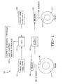
- FIG. 1 Represented in FIG. 1 is a schematic of a vehicle such as a farm tractor having a larger rearward wheel 12 and a smaller diameter front wheel 14.
- a vehicle ECU or other control means a sensor or transponder 16 is affixed or otherwise incorporated into a tire mounted on each wheel 12, 14.
- the invention is not intended to be hardware limited and any known sensor or transducer may be employed that meets the functional requirements of the system.
- the sensor and communication devices and systems identified above and incorporated herein by reference can functionally suffice.
- Other known sensor types and configurations may also be employed within the contemplation of the invention if so desired.
- each tire on wheels 12, 14, the sensor 16 rotates in unison with the tire.
- a single sensor 16 may be deployed as shown or, if desired, multiple sensors may be utilized as a failsafe. Multiple sensors will allow the system to function even if one or more sensors fail.
- the sensor 16 may be self-powered such as by battery or be energized by means of a radio frequency signal as discussed above.
- Associated with each sensor 16 typically is an antenna through which the sensor may communicate with a respective reader 18.
- Each reader 18 is powered by a system power supply 20 and is mounted remotely from a respective sensor 16 typically at a fixed location on the vehicle body or frame.
- Known readers may be employed for such a purpose.
- sensor 16 may comprise a pressure transducer that measures the pneumatic pressure within the tire cavity and transmits data to reader 18.
- the transducer/sensor 16 may comprise memory storage capability whereby tire specific identification data may be retained.
- the reader 18 may thus be programmed to read tire pressure and tire identification data from the transducer/sensor at regular or intermittent periods. Pursuant to the invention, the reader 18 may be programmed to count each revolution of an associate tire from communication with the sensor 16, whereby the rotational speed may be discerned. Other sensors may be incorporated by which other parameters such as tire air temperature can be measured and transmitted as data to reader 18 if so desired.
- An agricultural or farm vehicle is typically engine driven under the control of a computer commonly referred to as an electronic control unit (ECU) 22.
- the reader 18 may be wired as an input into the vehicle ECU 22 to transmit input data 26 relating to measured tire rotational rpm speed; tire identification information; and/or information indicating tire pneumatic pressure, temperature or other measured parameters.
- An algorithm in the ECU can determine the vehicle speed based on the tire revolutions per kilometer. With the input of tire pressure data from reader 18 obtained from sensor 16, the algorithm may take into account the effect of tire pressure on vehicle speed.
- the ECU algorithm In adjusting revolutions per kilometer by tire air pressure data, the ECU algorithm thus provides an accurate indication of vehicle speed and tire status. With this information, a number of useful applications may be served such as a calculation of the footprint length of each tire; the work efficacy of the vehicle derived from engine speed, traction of each tire, load, and vehicle speed. A wheel to wheel footprint and speed comparison by the ECU may further be used to analyze tire slippage and facilitate slippage elimination.
- One or more control signals may be generated by the ECU as a result of the data processing referenced above.
- Such outputs 24 may function to adjust engine controls whereby controlling tire/wheel speed and eliminating slippage; or communicate display data such as measured tire parameters and/or vehicle work efficacy to the vehicle operator. Slippage may be controlled to optimum levels for a given field condition. Work efficacy may thus be enhanced in informing the vehicle driver of traction, load, and speed data.
- the sensor 16 may be used to control an on-board tire pressure management, such as a central tire inflation system (CTIS).
- CTIS central tire inflation system
- a CTIS in agricultural or farm vehicles is configured to provide pressurized air to each tire automatically.
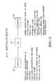
- FIG. 2 shows the subject system as ECU Inputs and Outputs.
- the inputs into the ECU 22 may be true tire characteristic at inflation pressures; tire inflation, numerical revolutions, and revolutions per mile or kilometer.
- Other vehicle information such as engine speed and measured ground speed (such as determined by radar or other means) may further be inputted into the ECU and used for comparison against algorithm generated results.
- Output signals from the ECU may be used to adjust speed differential between wheels/tires; control engine operation; adjust or eliminate wheel slippage; control CTIS operation to adjust pressure for maximum traction; and/or communicate information relating to work efficacy and vehicle speed to the vehicle operator.
- the subject invention can be used by original equipment manufacturers as the main input into their vehicle speed measurement and engine management systems.
- the invention may be used by the tire manufacturer to obtain relevant information about each tire that can be stored during manufacture such as Date Code, tire specification, and unique tire ID that is tied to the tire's uniformity as produced.
- Such tire specific data will be accessible by the vehicle ECU via reader 16 and the tire specific data for replacement tires may be readily compared to the tire specifications of the original tires.
- the subject invention is not hardware or software dependent. Relatively inexpensive sensors and readers that are commercially available in sundry form and configuration may be used. The subject system can thus inexpensively provide inputs to engine management systems that currently must rely on expensive radar systems for speed indication. The tire sensor/transponder can provide the same information, plus pressure measurement and storage of new tire information if desired.
Abstract
Description
- The present invention relates to a system and method of measuring a pneumatic tire condition and, more particularly to an integral system and method of measuring a farm tire condition and utilizing the measured condition in a plurality of applications.
- The present invention relates to monitoring one or more conditions of pneumatic tires mounted on wheels. As a rotary element, a tire's angular position, rotational (angular) velocity and acceleration, rate of change of acceleration, and revolution count are important in determining such things as vehicle and/or tire instantaneous position, speed, mileage, acceleration and braking, slip/skid, and are also factors in the wear of the tire.
- In addition to rotational/angular characteristics, other important characteristics to be monitored in a pneumatic tire are pneumatic pressure and temperature. Pressure (pneumatic pressure) is well known as a critical factor in pneumatic tire operation, most importantly if there is a loss of sufficient pressure to safely operate the tire, e.g., a "flat tire". The (pneumatic) temperature is generally of secondary importance. Although it can be used to indicate an average temperature of the tire and wheel surrounding the pneumatic cavity, temperature is mostly used to normalize a pressure measured in a hot tire to a "cold pressure" value, i.e., the pressure as it would be in a "cold" tire.
- A great deal of prior art is devoted to apparatus and methods for measuring and monitoring pneumatic tire conditions. US-B- 3,665,387 discloses a low tire pressure warning system adaptable for any number of wheels of a vehicle and providing dashboard indications of system operation and low pressure conditions while the vehicle is in motion.
- US-B- 4,911,217 discloses an RF transponder in a pneumatic tire. Figure 1 a of this patent illustrates a prior-art identification system ("reader") that can be used to interrogate and power the transponder within the tire. US-B-5,181,975 discloses a pneumatic tire having an integrated circuit (IC) transponder and pressure transducer. As described in this patent, in a tire that has already been manufactured, the transponder may be attached to an inner surface of the tire by means of a tire patch or other similar material or device.
- Dynamic conditions such as position and angular velocity of a rotary element are readily measured. Straightforward tire revolution counters are well known, represented by way of example in US-B- 4,842,486 and US-B-5,524,034. US-B-5,218,862 discloses a tire pressure monitor comprising wheel speed sensors located at the vehicle's wheels to convey wheel speed information to an electronic controller. This patent notes that the wheel speed discrepancy between one tire to the others indicates the relative tire pressure, but that discrepancy may also be indicative of the vehicle turning, accelerating or decelerating, going up or down steep grades, or of one wheel slipping, or of a cross wind bearing on the vehicle.
- From the foregoing, it is thus known to put transponders (and associated sensors) in pneumatic tires of motor vehicles. These transponders transmit a RF wave, with or without variable data (e.g., tire pressure, temperature, position) and/or fixed data (e.g., tire ID) to outside the tire, and receive RF signals, with or without data, from outside the tire. A separate transponder is typically associated with each tire of a motor vehicle to monitor and transmit tire-related data. Typically, an "interrogator" having both transmitting and receiving capabilities is used to communicate with the transponders.
- Such systems heretofore have been implemented primarily in passenger vehicle applications for the purpose of monitoring tire conditions such as pressure and temperature and communicating such information to the vehicle operator. Safety has been a primary consideration in such implementations. Application of such systems in tires for farm or agricultural vehicles has not, however, generally occurred. Accordingly, heretofore little attention and emphasis has been placed on creating expanded applications using pneumatic tire information generated from the implementation of tire monitoring systems in a farm tire.
- In farm vehicle applications, certain systems for measuring tire rotational speed have been applied as inputs to the vehicle's electronic control unit, typically a microprocessor. Such speed measuring systems are radar systems that are expensive to implement and maintain and cannot be used for other purposes such as storage of new tire information or for measuring tire parameters such as air pressure and temperature. There remains, therefore, a need in the industry for an inexpensive means for providing inputs to engine management systems that may be used for myriad agriculture applications. Moreover, such a system should be flexible and provide means for the storage of new tire information and for measuring other tire parameters such as air pressure and temperature. Still further, an ideal solution to the needs of the industry can be capable of use by OEM's as a main input directly into a vehicle's electronic control unit and be capable of use by a tire maker to store relevant information about the tire such as its Date Code, tire specification; and a tire identification tied to tire uniformity.
- Pursuant to one aspect of the invention, an integrated tire monitoring system for vehicle control system, preferably an agricultural vehicle control system, comprises a sensor integrally coupled to at least one tire on a vehicle, preferably a farm vehicle; an external reader for obtaining tire revolution speed data from the sensor during each revolution of the tire; input means for delivering the tire revolution speed data to a vehicle control unit, the vehicle control unit calculating vehicle speed based on the inputted tire revolution speed data and outputting at least one control signal.
- Pursuant to another aspect of the invention, the sensor measures pneumatic pressure within the vehicle tire; the reader obtains tire pressure data from the sensor and inputs the tire pressure data into the vehicle control unit; and the vehicle control unit utilizes the inputted tire pressure data to calculate a pressure adjusted vehicle speed.
- Pursuant to yet another aspect of the invention, the sensor may store tire specific identification data accessible by the external reader.
- According to another aspect of the invention, the control signal may be used to control a vehicle parameter selected from the group: adjustment of speed between a plurality of vehicle wheels; engine speed; wheel slippage and tire air pressure. The vehicle control unit may further evaluate work efficacy of the vehicle based upon the calculated vehicle speed and communicate results of the evaluation of work efficacy to an operator of the vehicle.
- Another aspect of the invention is for a method of integrating a tire monitoring system into a farm vehicle control system comprising the steps: coupling a sensor integrally into at least one tire on a farm vehicle; obtaining tire revolution speed data from the sensor by means of an external reader during each revolution of the tire; inputting tire revolution speed data into a vehicle control unit; calculating vehicle speed based on inputted tire revolution speed data; and outputting a control signal from the vehicle control unit based upon the calculated vehicle speed.
- According to one aspect of the invention, the method comprises the further steps of utilizing the control signal to control a vehicle parameter selected from the group: adjustment of speed between a plurality of vehicle wheels; engine speed; wheel slippage and tire air pressure.
- Other aspects, features and advantages of the invention will become apparent in light of the following drawings and specification.
- The invention will be described by way of example and with reference to the accompanying drawings in which:
- FIG. 1 is a schematic representation of an integrated sensor system for farm tires configured pursuant to the invention; and
- FIG. 2 is a schematic representation showing ECU inputs and outputs in a system configured pursuant to the invention.
- With reference to FIGS. 1 and 2, an integrated
tire monitoring system 10 for an agricultural vehicle is represented in schematic form. As used herein, "agriculture", "agricultural", "farm", are used interchangeably in a non-limiting manner. Such references are to a broad range of applications and wheeled apparatus that operate primarily off-road on unpaved surfaces. Such applications include but are not intended to be limited to: construction site equipment such as tractors and earth moving equipment; and farm related equipment such as tractors, combines, wagons, earth conditioning equipment, etc. Equipment used in all such applications operates on wheeled frames having a pneumatic tire mounted to each wheel. In addition, modern equipment of the type referred to herein generically as "farm" or "agricultural" include either directly or indirectly an engine driven vehicle typically controlled by an electronic control unit (ECU) such as a microprocessor. - Represented in FIG. 1 is a schematic of a vehicle such as a farm tractor having a larger
rearward wheel 12 and a smaller diameterfront wheel 14. One or bothwheels transponder 16 is affixed or otherwise incorporated into a tire mounted on eachwheel wheels sensor 16 rotates in unison with the tire. Asingle sensor 16 may be deployed as shown or, if desired, multiple sensors may be utilized as a failsafe. Multiple sensors will allow the system to function even if one or more sensors fail. Thesensor 16 may be self-powered such as by battery or be energized by means of a radio frequency signal as discussed above. Associated with each sensor 16 (not shown) typically is an antenna through which the sensor may communicate with arespective reader 18. - Each
reader 18 is powered by asystem power supply 20 and is mounted remotely from arespective sensor 16 typically at a fixed location on the vehicle body or frame. Known readers may be employed for such a purpose. As eachsensor 16 rotates, it is brought into a suitably proximal relationship to arespective reader 18 to enable communication between the sensor and its associate reader. Communication between each sensor and its respective reader may be by radio frequency transmission or other transmitting frequencies. It will be appreciated by those skilled in the art thatsensor 16 may comprise a pressure transducer that measures the pneumatic pressure within the tire cavity and transmits data toreader 18. Moreover, pursuant to the invention, the transducer/sensor 16 may comprise memory storage capability whereby tire specific identification data may be retained. Thereader 18 may thus be programmed to read tire pressure and tire identification data from the transducer/sensor at regular or intermittent periods. Pursuant to the invention, thereader 18 may be programmed to count each revolution of an associate tire from communication with thesensor 16, whereby the rotational speed may be discerned. Other sensors may be incorporated by which other parameters such as tire air temperature can be measured and transmitted as data toreader 18 if so desired. - An agricultural or farm vehicle is typically engine driven under the control of a computer commonly referred to as an electronic control unit (ECU) 22. The
reader 18 may be wired as an input into thevehicle ECU 22 to transmitinput data 26 relating to measured tire rotational rpm speed; tire identification information; and/or information indicating tire pneumatic pressure, temperature or other measured parameters. An algorithm in the ECU can determine the vehicle speed based on the tire revolutions per kilometer. With the input of tire pressure data fromreader 18 obtained fromsensor 16, the algorithm may take into account the effect of tire pressure on vehicle speed. - In adjusting revolutions per kilometer by tire air pressure data, the ECU algorithm thus provides an accurate indication of vehicle speed and tire status. With this information, a number of useful applications may be served such as a calculation of the footprint length of each tire; the work efficacy of the vehicle derived from engine speed, traction of each tire, load, and vehicle speed. A wheel to wheel footprint and speed comparison by the ECU may further be used to analyze tire slippage and facilitate slippage elimination.
- One or more control signals may be generated by the ECU as a result of the data processing referenced above.
Such outputs 24 may function to adjust engine controls whereby controlling tire/wheel speed and eliminating slippage; or communicate display data such as measured tire parameters and/or vehicle work efficacy to the vehicle operator. Slippage may be controlled to optimum levels for a given field condition. Work efficacy may thus be enhanced in informing the vehicle driver of traction, load, and speed data. Moreover, thesensor 16 may be used to control an on-board tire pressure management, such as a central tire inflation system (CTIS). A CTIS in agricultural or farm vehicles is configured to provide pressurized air to each tire automatically. - FIG. 2 shows the subject system as ECU Inputs and Outputs. As discussed above, the inputs into the
ECU 22 may be true tire characteristic at inflation pressures; tire inflation, numerical revolutions, and revolutions per mile or kilometer. Other vehicle information such as engine speed and measured ground speed (such as determined by radar or other means) may further be inputted into the ECU and used for comparison against algorithm generated results. Output signals from the ECU may be used to adjust speed differential between wheels/tires; control engine operation; adjust or eliminate wheel slippage; control CTIS operation to adjust pressure for maximum traction; and/or communicate information relating to work efficacy and vehicle speed to the vehicle operator. - From the forgoing, it will be appreciated that the subject invention can be used by original equipment manufacturers as the main input into their vehicle speed measurement and engine management systems. The invention may be used by the tire manufacturer to obtain relevant information about each tire that can be stored during manufacture such as Date Code, tire specification, and unique tire ID that is tied to the tire's uniformity as produced. Such tire specific data will be accessible by the vehicle ECU via
reader 16 and the tire specific data for replacement tires may be readily compared to the tire specifications of the original tires. - It will further be noted that the subject invention is not hardware or software dependent. Relatively inexpensive sensors and readers that are commercially available in sundry form and configuration may be used. The subject system can thus inexpensively provide inputs to engine management systems that currently must rely on expensive radar systems for speed indication. The tire sensor/transponder can provide the same information, plus pressure measurement and storage of new tire information if desired.
Claims (10)
- An integrated tire monitoring system, the system (10) comprising:a sensor (16) integrally coupled to at least one tire on a vehicle;an external reader (18) for obtaining tire revolution speed data from the sensor during each revolution of the tire; andinput means for delivering the tire revolution speed data to a vehicle control unit (22), the vehicle control unit calculating vehicle speed based on the inputted tire revolution speed data and outputting at least one control signal.
- The integrated tire pressure monitoring system according to claim 1, wherein the sensor measures pneumatic pressure within the vehicle tire;
- The integrated tire pressure monitoring system according to claim 2, wherein the reader obtains tire pressure data from the sensor and inputs the tire pressure data into the vehicle control unit and wherein the vehicle control unit utilizes the inputted tire pressure data to calculate a pressure adjusted vehicle speed.
- The integrated tire pressure monitoring system according to at least one of the previous claims, wherein the sensor stores tire specific identification data accessible by the external reader.
- The integrated tire pressure monitoring system according to at least one of the previous claims, wherein the control signal is used to control a vehicle parameter selected from the group: adjustment of speed between a plurality of vehicle wheels, engine speed, wheel slippage and tire air pressure.
- The integrated tire pressure monitoring system according to at least one of the previous claims, wherein the vehicle control unit evaluates work efficacy of the vehicle based upon the calculated vehicle speed and communicates results of the evaluation of work efficacy to an operator of the vehicle.
- The system according to at least one of the previous claims, wherein the system is for an agricultural vehicle control system and the vehicle is a farm vehicle.
- A method of integrating a tire monitoring system into a vehicle control system, the method comprising the steps:a) coupling a sensor (16) integrally into at least one tire on a vehicle;b) obtaining tire revolution speed data from the sensor by means of an external reader (18) during each revolution of the tire;c) inputting tire revolution speed data into a vehicle control unit (22);d) calculating vehicle speed based on inputted tire revolution speed data; ande) outputting a control signal from the vehicle control unit based upon the calculated vehicle speed.
- The method according to claim 8, further comprising the steps:measuring a tire pressure with the sensor;obtaining tire pressure data from the sensor by operation of the external reader;inputting tire pressure data into the vehicle control unit; andutilizing the inputted tire pressure data to calculate a pressure adjusted vehicle speed.
- The method according to claim 8 or 9, further comprising the steps:storing tire specific identification data in the sensor;accessing the tire specific identification data by operation of the external reader.
Applications Claiming Priority (1)
| Application Number | Priority Date | Filing Date | Title |
|---|---|---|---|
| US11/021,653 US7295103B2 (en) | 2004-12-22 | 2004-12-22 | Integrated sensor system and method for a farm tire |
Publications (2)
| Publication Number | Publication Date |
|---|---|
| EP1674300A2 true EP1674300A2 (en) | 2006-06-28 |
| EP1674300A3 EP1674300A3 (en) | 2010-04-28 |
Family
ID=36228662
Family Applications (1)
| Application Number | Title | Priority Date | Filing Date |
|---|---|---|---|
| EP05112205A Withdrawn EP1674300A3 (en) | 2004-12-22 | 2005-12-15 | Integrated sensor system and method for a tire |
Country Status (3)
| Country | Link |
|---|---|
| US (1) | US7295103B2 (en) |
| EP (1) | EP1674300A3 (en) |
| CA (1) | CA2520557C (en) |
Cited By (2)
| Publication number | Priority date | Publication date | Assignee | Title |
|---|---|---|---|---|
| CN105490803A (en) * | 2014-10-07 | 2016-04-13 | 通用汽车环球科技运作有限责任公司 | Distributing secret keys for managing access to ECUs |
| DE102017208528A1 (en) * | 2017-05-19 | 2018-11-22 | Bayerische Motoren Werke Aktiengesellschaft | Vehicle wheel assembly with at least two sensors and method for transmitting electrical energy to such |
Families Citing this family (16)
| Publication number | Priority date | Publication date | Assignee | Title |
|---|---|---|---|---|
| DE102007035647A1 (en) * | 2007-07-27 | 2009-01-29 | Claas Selbstfahrende Erntemaschinen Gmbh | Agricultural working machine |
| DE102008003845A1 (en) * | 2008-01-10 | 2009-07-16 | Robert Bosch Gmbh | Tire pressure monitoring device for monitoring the air pressure in a tire with acceleration detection by the tire pressure sensor |
| US20110148593A1 (en) * | 2009-12-17 | 2011-06-23 | Robert Leon Benedict | Method for reading a vehicle tag within a read station |
| US9135479B2 (en) * | 2009-12-17 | 2015-09-15 | The Goodyear Tire & Rubber Company | Antenna assembly for a tag reader |
| US8612088B2 (en) | 2011-04-14 | 2013-12-17 | Robert Bosch Gmbh | Tire pressure monitoring systems and methods |
| US8596117B2 (en) | 2011-10-03 | 2013-12-03 | Bridgestone Americas Tire Operations, Llc | Attachment patch for mounting various devices |
| TWI432762B (en) * | 2011-12-07 | 2014-04-01 | Ind Tech Res Inst | Radar wave sensing apparatus and method |
| US9296263B2 (en) * | 2011-12-23 | 2016-03-29 | Prasad Muthukumar | Smart active tyre pressure optimising system |
| WO2013118144A2 (en) * | 2012-02-02 | 2013-08-15 | Tata Consultancy Services Limited | A system and method for identifying and analyzing personal context of a user |
| JP5932485B2 (en) * | 2012-05-25 | 2016-06-08 | キヤノン株式会社 | Noise reduction device and noise reduction method |
| US20140300451A1 (en) * | 2013-04-09 | 2014-10-09 | Deere & Company | Vehicle configuration system |
| WO2016099633A1 (en) | 2014-12-19 | 2016-06-23 | Bridgestone Americas Tire Operations, Llc | Attachment patch for mounting devices |
| US10816415B2 (en) * | 2016-02-11 | 2020-10-27 | The University Of Akron | Flexible sensors and methods for making the same |
| US10935466B2 (en) * | 2017-12-20 | 2021-03-02 | The Goodyear Tire & Rubber Company | Integrated tire sensor and reader system |
| US10820474B2 (en) | 2018-10-11 | 2020-11-03 | Cnh Industrial Canada, Ltd. | System for estimating field conditions and associated methods for adjusting operating parameters of an agricultural machine based on estimated field conditions |
| JP2022099084A (en) | 2020-12-22 | 2022-07-04 | 株式会社クボタ | Agricultural machine, and system and method controlling the same |
Citations (9)
| Publication number | Priority date | Publication date | Assignee | Title |
|---|---|---|---|---|
| US3665387A (en) | 1970-08-31 | 1972-05-23 | Goodyear Tire & Rubber | Signalling system for low tire condition on a vehicle |
| US4842486A (en) | 1985-12-19 | 1989-06-27 | Siemens Aktiengesellschaft | Method and apparatus for increasing the operating efficiency of a liquid-flow machine |
| US4911217A (en) | 1989-03-24 | 1990-03-27 | The Goodyear Tire & Rubber Company | Integrated circuit transponder in a pneumatic tire for tire identification |
| US5181975A (en) | 1991-03-27 | 1993-01-26 | The Goodyear Tire & Rubber Company | Integrated circuit transponder with coil antenna in a pneumatic tire for use in tire identification |
| US5218862A (en) | 1992-01-21 | 1993-06-15 | General Motors Corporation | Tire pressure monitor |
| EP0689950A2 (en) * | 1994-06-03 | 1996-01-03 | BRIDGESTONE/FIRESTONE, Inc. | Method of monitoring conditions of vehicle tires and tires containing a monitoring device therein |
| US5524034A (en) | 1992-05-04 | 1996-06-04 | S & A Systems, Inc. | Automatic revolution counting and data transmission device |
| US6255940B1 (en) * | 1999-10-01 | 2001-07-03 | The Goodyear Tire & Rubber Company | Apparatus for monitoring a condition of a tire |
| US20030058118A1 (en) * | 2001-05-15 | 2003-03-27 | Wilson Kitchener C. | Vehicle and vehicle tire monitoring system, apparatus and method |
Family Cites Families (6)
| Publication number | Priority date | Publication date | Assignee | Title |
|---|---|---|---|---|
| US6144295A (en) * | 1998-12-11 | 2000-11-07 | Case Corporation | Automatic central tire inflation system |
| US6434470B1 (en) * | 2000-12-05 | 2002-08-13 | Lear Corporation | Tire pressure vehicle speed limiting |
| EP1215096B1 (en) * | 2000-12-14 | 2011-04-06 | Sumitomo Rubber Industries, Ltd. | Apparatus and method for identifying tires and apparatus and method for evaluating road surface conditions |
| AU2002345967A1 (en) * | 2001-06-25 | 2003-01-08 | 3Dm Technologies, Inc. | Tire sensor |
| TW539627B (en) * | 2001-12-17 | 2003-07-01 | Taiheiyo Kogyo Kk | Apparatus and method for monitoring tire condition |
| US7945361B2 (en) * | 2003-07-04 | 2011-05-17 | Pirelli Pneumatici S.P.A. | Method and system for determining a tyre load during the running of a motor vehicle |
-
2004
- 2004-12-22 US US11/021,653 patent/US7295103B2/en not_active Expired - Fee Related
-
2005
- 2005-09-22 CA CA2520557A patent/CA2520557C/en not_active Expired - Fee Related
- 2005-12-15 EP EP05112205A patent/EP1674300A3/en not_active Withdrawn
Patent Citations (9)
| Publication number | Priority date | Publication date | Assignee | Title |
|---|---|---|---|---|
| US3665387A (en) | 1970-08-31 | 1972-05-23 | Goodyear Tire & Rubber | Signalling system for low tire condition on a vehicle |
| US4842486A (en) | 1985-12-19 | 1989-06-27 | Siemens Aktiengesellschaft | Method and apparatus for increasing the operating efficiency of a liquid-flow machine |
| US4911217A (en) | 1989-03-24 | 1990-03-27 | The Goodyear Tire & Rubber Company | Integrated circuit transponder in a pneumatic tire for tire identification |
| US5181975A (en) | 1991-03-27 | 1993-01-26 | The Goodyear Tire & Rubber Company | Integrated circuit transponder with coil antenna in a pneumatic tire for use in tire identification |
| US5218862A (en) | 1992-01-21 | 1993-06-15 | General Motors Corporation | Tire pressure monitor |
| US5524034A (en) | 1992-05-04 | 1996-06-04 | S & A Systems, Inc. | Automatic revolution counting and data transmission device |
| EP0689950A2 (en) * | 1994-06-03 | 1996-01-03 | BRIDGESTONE/FIRESTONE, Inc. | Method of monitoring conditions of vehicle tires and tires containing a monitoring device therein |
| US6255940B1 (en) * | 1999-10-01 | 2001-07-03 | The Goodyear Tire & Rubber Company | Apparatus for monitoring a condition of a tire |
| US20030058118A1 (en) * | 2001-05-15 | 2003-03-27 | Wilson Kitchener C. | Vehicle and vehicle tire monitoring system, apparatus and method |
Cited By (3)
| Publication number | Priority date | Publication date | Assignee | Title |
|---|---|---|---|---|
| CN105490803A (en) * | 2014-10-07 | 2016-04-13 | 通用汽车环球科技运作有限责任公司 | Distributing secret keys for managing access to ECUs |
| CN105490803B (en) * | 2014-10-07 | 2018-10-02 | 通用汽车环球科技运作有限责任公司 | The method for controlling the access to electronic control unit |
| DE102017208528A1 (en) * | 2017-05-19 | 2018-11-22 | Bayerische Motoren Werke Aktiengesellschaft | Vehicle wheel assembly with at least two sensors and method for transmitting electrical energy to such |
Also Published As
| Publication number | Publication date |
|---|---|
| CA2520557C (en) | 2012-04-17 |
| US20060145828A1 (en) | 2006-07-06 |
| CA2520557A1 (en) | 2006-06-22 |
| US7295103B2 (en) | 2007-11-13 |
| EP1674300A3 (en) | 2010-04-28 |
Similar Documents
| Publication | Publication Date | Title |
|---|---|---|
| CA2520557C (en) | Integrated sensor system and method for a farm tire | |
| US5749984A (en) | Tire monitoring system and method | |
| US10809742B2 (en) | System and method for tire sensor-based autonomous vehicle fleet management | |
| EP0887211B1 (en) | Tire monitoring system | |
| US6731205B2 (en) | Self training tire pressure monitoring system | |
| EP3121034B1 (en) | Tread wear estimation system and method | |
| EP0800464B1 (en) | System and method for monitoring tire inflation pressure in a vechicle tire and wheel assembly | |
| US6581449B1 (en) | Low pressure warning system for pneumatic tires with RF tags and monitors for each tire | |
| US7000462B2 (en) | System for monitoring a vehicle with pneumatic tires, signal analysis method, and vehicle tire | |
| EP3168064A1 (en) | Tire sensor-based robust mileage tracking system and method | |
| EP3785943B1 (en) | Tire wear state estimation system and method employing footprint length | |
| EP2812829A2 (en) | Wireless proportional flow indication for a tire inflation system | |
| US20030010107A1 (en) | Tire status detection system | |
| US9448139B2 (en) | Method, control unit, and system for determining a parameter that indicates a state of at least one component of a motor vehicle | |
| US6778075B2 (en) | Tire inflation monitoring system | |
| EP3785944A1 (en) | Tire wear state estimation system and method employing footprint shape factor | |
| US20070247294A1 (en) | Method and Apparatus for Monitoring Wheels of a Motor Vehicle | |
| EP3423295B1 (en) | Wheel unit, system for transmitting data from a wheel unit, and method for transmitting data from a wheel unit | |
| WO2013015780A1 (en) | System for predicting residual tire endurance limit in real-time | |
| JP2022547378A (en) | Position Sensing System and Method for Locating Tire Pressure Monitoring Sensors Using Correlation with Wheel Edge Sensors | |
| EP1220756A1 (en) | Low pressure warning system (lpws) for pneumatic tires | |
| EP4112335A1 (en) | Tire pressure monitoring system and method employing axle cross comparison |
Legal Events
| Date | Code | Title | Description |
|---|---|---|---|
| PUAI | Public reference made under article 153(3) epc to a published international application that has entered the european phase |
Free format text: ORIGINAL CODE: 0009012 |
|
| AK | Designated contracting states |
Kind code of ref document: A2 Designated state(s): AT BE BG CH CY CZ DE DK EE ES FI FR GB GR HU IE IS IT LI LT LU LV MC NL PL PT RO SE SI SK TR |
|
| AX | Request for extension of the european patent |
Extension state: AL BA HR MK YU |
|
| PUAL | Search report despatched |
Free format text: ORIGINAL CODE: 0009013 |
|
| AK | Designated contracting states |
Kind code of ref document: A3 Designated state(s): AT BE BG CH CY CZ DE DK EE ES FI FR GB GR HU IE IS IT LI LT LU LV MC NL PL PT RO SE SI SK TR |
|
| AX | Request for extension of the european patent |
Extension state: AL BA HR MK YU |
|
| 17P | Request for examination filed |
Effective date: 20101028 |
|
| 17Q | First examination report despatched |
Effective date: 20101125 |
|
| AKX | Designation fees paid |
Designated state(s): DE ES FR IT PL |
|
| STAA | Information on the status of an ep patent application or granted ep patent |
Free format text: STATUS: THE APPLICATION IS DEEMED TO BE WITHDRAWN |
|
| 18D | Application deemed to be withdrawn |
Effective date: 20141202 |