EP1302178A2 - Handle deployment mechanism for medical device & method - Google Patents
Handle deployment mechanism for medical device & method Download PDFInfo
- Publication number
- EP1302178A2 EP1302178A2 EP02257071A EP02257071A EP1302178A2 EP 1302178 A2 EP1302178 A2 EP 1302178A2 EP 02257071 A EP02257071 A EP 02257071A EP 02257071 A EP02257071 A EP 02257071A EP 1302178 A2 EP1302178 A2 EP 1302178A2
- Authority
- EP
- European Patent Office
- Prior art keywords
- medical device
- shaft member
- delivery system
- inner shaft
- device delivery
- Prior art date
- Legal status (The legal status is an assumption and is not a legal conclusion. Google has not performed a legal analysis and makes no representation as to the accuracy of the status listed.)
- Granted
Links
Images


Classifications
-
- A—HUMAN NECESSITIES
- A61—MEDICAL OR VETERINARY SCIENCE; HYGIENE
- A61F—FILTERS IMPLANTABLE INTO BLOOD VESSELS; PROSTHESES; DEVICES PROVIDING PATENCY TO, OR PREVENTING COLLAPSING OF, TUBULAR STRUCTURES OF THE BODY, e.g. STENTS; ORTHOPAEDIC, NURSING OR CONTRACEPTIVE DEVICES; FOMENTATION; TREATMENT OR PROTECTION OF EYES OR EARS; BANDAGES, DRESSINGS OR ABSORBENT PADS; FIRST-AID KITS
- A61F2/00—Filters implantable into blood vessels; Prostheses, i.e. artificial substitutes or replacements for parts of the body; Appliances for connecting them with the body; Devices providing patency to, or preventing collapsing of, tubular structures of the body, e.g. stents
- A61F2/95—Instruments specially adapted for placement or removal of stents or stent-grafts
- A61F2/9517—Instruments specially adapted for placement or removal of stents or stent-grafts handle assemblies therefor
-
- A—HUMAN NECESSITIES
- A61—MEDICAL OR VETERINARY SCIENCE; HYGIENE
- A61M—DEVICES FOR INTRODUCING MEDIA INTO, OR ONTO, THE BODY; DEVICES FOR TRANSDUCING BODY MEDIA OR FOR TAKING MEDIA FROM THE BODY; DEVICES FOR PRODUCING OR ENDING SLEEP OR STUPOR
- A61M25/00—Catheters; Hollow probes
- A61M25/01—Introducing, guiding, advancing, emplacing or holding catheters
- A61M25/09—Guide wires
- A61M2025/09116—Design of handles or shafts or gripping surfaces thereof for manipulating guide wires
Definitions
- the present invention relates generally to medical devices, and more particularly to a medical device delivery system with an improved two-way handle having a compound mechanism.
- the present invention involves medical devices, and also the delivery systems used to convey them to a desired location for treatment, and then deploy them in position.
- Many such medical devices are resiliently compressed to a smaller initial size for containment, protection, storage and eventual delivery from inside a catheter system. Upon deployment, the medical devices may resiliently expand to a larger deployed size.
- the disclosed stent includes coaxially arranged inner and outer catheter members, each having a hub affixed to its proximal end.
- the outer sheath is described in the '778 document as an elongated tubular member having distal and proximal ends, which is made from an outer polymeric layer, an inner polymeric layer, and a braided reinforcing layer between them.
- the inner shaft is described in the '778 document as being located coaxially within the outer sheath and has a flexible tapering distal end, which generally extends distally beyond the distal end of the outer sheath.
- the inner shaft member also is shown as including a stop which is positioned proximal from the distal end of the outer sheath.
- a self-expanding stent is located within the outer sheath, and is located between the stop on the inner shaft member and the outer sheath distal end. To deploy the stent the outer sheath is withdrawn by a physician in a proximal direction, while the inner shaft member is held in position.
- these known medical device delivery systems are generally advanced within a body of a patient along a desired vascular path or other body passageway, until the medical device within the catheter system is located at a desired site for treatment. While watching the relative positions of the medical device and the catheter system components with respect to a stenosis on a video x-ray fluoroscopy screen, the physician holds the proximal hub attached to the inner shaft member in a fixed position with one hand, while simultaneously gently withdrawing the proximal hub attached to the outer tubular sheath with the other hand.
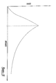
- this deployment operation may require some measure of delicate skill. For example, among these reasons is the dynamic blood flow at the desired site for treatment, which may be further disrupted by the presence of a lesion or stenosis to be treated. Another factor is the gradual resilient expansion of a medical device as the outer sheath is retracted. This gradual expansion presents an opportunity for a possible reverse "watermelon-seed” phenomenon to occur. This reverse watermelon-seed effect may cause the resilient medical device to tend to push the outer sheath back in a proximal direction with a force that tends to follow a curve similar shown in Figure 15.
- the physician may need to accurately hold the two proximal hubs in a specific relative position, holding them against this expansion force, while attempting to very accurately position the medical device up until contact with the anatomy.
- One of the possibilities that may affect the positioning of the deployed medical device is that the inner shaft should preferably be held stationary in the desired position. If the physician's hand that holds the inner shaft hub does inadvertently move during deployment, it is possible that the medical device may be deployed in a non-optimum position.
- the inner and outer catheter shaft members do not have infinite column strength, which may present an opportunity for the position and movement of each proximal hub to differ from the position and movement of the respective distal ends of the inner and outer shaft members.
- the position of the medical device may be adjusted up until the point at which a portion of the expanding portion of the medical device touches the sidewalls of the body passage, so that the position of the medical device should preferably be carefully adjusted until immediately before a portion of the medical device touches the anatomy.
- Some known catheter systems require two-handed operation, such as those with a pair of independent hubs, one hub on the inner and outer shaft member, respectively.
- Other known catheter systems include a pistol and trigger grip, with a single mode of deployment, involving a single trigger pull to deploy the associated medical device.
- the delivery mechanism preferably provides a precisely adjustable link between the inner and outer catheter shaft members, such that the relative position of the outer sheath with respect to the inner catheter shaft member can be precisely and selectively adjusted. Yet at any selected position, the delivery mechanism should preferably maintain this selected relative position of the inner and outer catheter shaft members, while resisting any force that may be present tending to move the inner or the outer catheter shaft members with respect to the other.
- the delivery mechanism should preferably enable the physician to rapidly withdraw the outer tubular sheath with respect to the inner catheter shaft member preferably in a proximal direction with a single easy motion.
- the present invention provides such a desirable medical device delivery mechanism, with an integrated handle replacing the functions of the separate proximal hubs of the prior inner and outer catheter shaft members, and also providing desired dual modes of operation.
- a medical device delivery system is depicted, with one of the preferred embodiments of the present invention being shown at 10.
- the illustrated stent delivery catheter system 10 of course depicts only one of many different medical device delivery systems designs that are contemplated. For clarity and convenience, the present detailed description will only describe such an example of a delivery system for stents.
- One possible medical device delivery system that may be used with the present invention is any appropriate system in which an outer sheath is provided, surrounding an inner shaft.
- a medical device may be carried within the outer sheath during delivery to a desired site for treatment, where the outer sheath may be retracted, while the inner shaft and medical device are held in place.
- novel concept of the present invention may also be used for medical device delivery systems in which the motion of the operator to deploy the medical device is selected from any suitable possibility, including axial motion in the proximal direction or the distal direction, or a rotational motion, a trigger actuator, a gear mechanism, or any other type of actuator that may be preferred, depending upon a particular application.
- the present unique concept may be used for medical device delivery systems in which the medical device is deployed in any suitable manner, including retracting an outer sheath in a proximal direction or a distal direction, or uncovering a medical device in various ways, including withdrawing portions of outer sheath members in proximal and distal directions, simultaneously or sequentially.
- the present invention may provide several advantages individually, or any combination of such advantages, including for example: (i) single-handed operation of the medical device delivery system; (ii) a mechanism providing leverage or mechanical advantage, to adjust or reduce the forces needed to operate the system; (iii) improved accuracy in positioning the medical device during deployment; (iv) a capability of holding the delivery system components in a fixed relative position during an intermediate point in deploying a medical device; and (v) multiple operational modes of operation, including for example a first mode of fine and precise control of the deployment process, and a second mode of rapid and easy deployment.
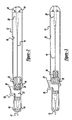
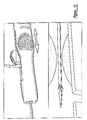
- the particular embodiment 10 of the present invention selected for illustration in the drawings includes a handle, shown in detail in Figures 1-6.
- a first and second main body housing 12 and 14 are arranged in a side-by-side configuration, as shown for example in Figure 1.
- Other components include inner and outer shaft members 16 and 18 respectively, an anchoring member 20, a proximal hub 22 with an actuator or knob 24 and a corresponding flush lumen tube 26 and valve 28, as well as a threaded base member 30 and a rotating finger ring 32.
- the main body housings 12 and 14 each preferably have several gripping knurls 34 for providing a physician with a good gripping surface, a longitudinal slot 36 defining a channel for sliding the movable actuator 24 and limiting the extent of possible travel for the actuator 24 and proximal hub assembly 22, a side opening 38 through which a physician can operate the rotating finger ring 32, a proximal anchoring aperture 40 adapted to capture a portion of the anchoring member 20, a distal shaft aperture 42 through which the inner and outer shaft members 16 and 18 extend, and several openings for receiving fasteners 44 to hold the main body housings 12 and 14 together.
- the main body housings 12 and 14 also define a circular annular bearing shelf or shoulder 46.
- a distal surface of rotating finger ring 32 touches this shoulder 46 in an initial configuration, and rotation of the rotating finger ring 32 causes it to advance along threaded base 30 and press on shoulder 46, resulting in very precise and sensitive withdrawing movement of outer shaft member 18 in a proximal direction.
- Anchor aperture 40 fixedly receives anchor 20, which is affixed to the proximal end of inner shaft member 16.
- a proximal end of outer shaft member 18 is affixed to proximal hub 22, with a flexible strain relief 48 protecting the joint.
- proximal hub 22 is affixed to threaded base 30, which rotatably carries rotating finger ring 32, which bears on the shoulder 46 of main body housing 12.
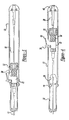
- the preferred dual operation of the present invention is accomplished by enabling movement of outer shaft member 18 with respect to inner shaft member 16 in two ways. First, by rotating the finger ring 32 to cause it to advance on threaded base 30 and press against shoulder 46, such that the entire assembly of threaded base 30, proximal hub 22 and outer shaft member 18 withdraw proximally with respect to main body housing 12 and 14, and thus with respect to inner shaft member 16. Second, by simply grasping knob 24 and pulling or pushing it within slot 36. The first method allows precise and sensitive adjustment, while the second method allows relatively large-scale and rapid movement.
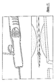
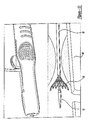
- a stent 50 At the distal end of the medical device delivery system, shown in detail in Figures 7-9, distal ends of the inner and outer shaft members 16 and 18 are depicted, as well as whatever medical device is selected, in this particular case a stent 50.
- the stent 50 shown in the drawings is of the self-expanding type, and may be captured within a tubular capsule 52 affixed to outer shaft member 18.
- the distal end of inner shaft member 16 may be provided with a flexible tapering distal tip 54.
- At least a proximal annular stop 56, and preferably also a distal annular ring 58, are affixed to inner shaft member 16.
- the stop 56 and ring 58, as well as a distal marker 60 that may be provided, are preferably radiopaque.
- inner shaft member 16 assembly including anchor 20, inner shaft member 16 and distal tip 54, may preferably be provided with a through lumen adapted to receive a guidewire 62.
- the medical device delivery system 10 is advanced via a body passageway, preferably along a guidewire 62, until the stent 50 is located within a desired site for treatment.
- a physician gently rotates the finger ring 32 to slightly pull back outer shaft member 18.
- a small portion of the stent 50 may expand slightly.
- the handle of the present invention comfortably holds the delivery system 10 in this intermediate configuration, allowing the physician time and flexibility of procedure to selectively optimize the position of the stent 50 within the desired site. This precise adjustment of the position of the stent 50, before any portion of the stent 50 touches the body passage or vessel 64 in a manner that might inhibit further positional adjustment, is preferable.
- the finger ring 32 may be further rotated to cause a distal end of the stent 50 to gently contact the vessel 64.
- the stent is expanded sufficiently to independently hold its position, it is desirable to rapidly and completely withdraw the outer shaft member 18.
- the physician grasps the knob 24 and pulls it back along slot 36. The outer shaft member 18 may thus be withdrawn as quickly as the physician wishes.
- the inner and outer shaft members 16 and 18, strain relief 48, and distal tip 54 may be made of any biocompatible and suitably flexible yet sufficiently strong material, including polymers of various types. Possible selections for such materials include nylons or polyamides, polyimides, polyethylenes, polyurethanes, polyethers, polyesters, etc.
- some portion or all of the inner and/or outer shaft member 16, 18 may be formed of a flexible metal, including for example stainless steel or nitinol hypotube.
- the stent 50, stop 56, ring 58, marker 60 are preferably made of any biocompatible material that is strong and rigid, including for example stainless steel, platinum, tungsten, etc.
- the components of the handle of the present invention are preferably made of a material that is strong and rigid, including for example inflexible polycarbonates, or even some metal components.
Abstract
Description
- The present invention relates generally to medical devices, and more particularly to a medical device delivery system with an improved two-way handle having a compound mechanism.
- The present invention involves medical devices, and also the delivery systems used to convey them to a desired location for treatment, and then deploy them in position. Many such medical devices are resiliently compressed to a smaller initial size for containment, protection, storage and eventual delivery from inside a catheter system. Upon deployment, the medical devices may resiliently expand to a larger deployed size.
- A successful example of a delivery catheter system, in this case for a self-expanding stent, is disclosed in US-6019778. As shown in Figure 10 of that document, the disclosed stent includes coaxially arranged inner and outer catheter members, each having a hub affixed to its proximal end. The outer sheath is described in the '778 document as an elongated tubular member having distal and proximal ends, which is made from an outer polymeric layer, an inner polymeric layer, and a braided reinforcing layer between them. The inner shaft is described in the '778 document as being located coaxially within the outer sheath and has a flexible tapering distal end, which generally extends distally beyond the distal end of the outer sheath. The inner shaft member also is shown as including a stop which is positioned proximal from the distal end of the outer sheath. A self-expanding stent is located within the outer sheath, and is located between the stop on the inner shaft member and the outer sheath distal end. To deploy the stent the outer sheath is withdrawn by a physician in a proximal direction, while the inner shaft member is held in position.
- Additional examples of different types of known self-expanding stent delivery systems are disclosed in US-4580568 and US-4732152.
- In operation, these known medical device delivery systems are generally advanced within a body of a patient along a desired vascular path or other body passageway, until the medical device within the catheter system is located at a desired site for treatment. While watching the relative positions of the medical device and the catheter system components with respect to a stenosis on a video x-ray fluoroscopy screen, the physician holds the proximal hub attached to the inner shaft member in a fixed position with one hand, while simultaneously gently withdrawing the proximal hub attached to the outer tubular sheath with the other hand.
- For several reasons, this deployment operation may require some measure of delicate skill. For example, among these reasons is the dynamic blood flow at the desired site for treatment, which may be further disrupted by the presence of a lesion or stenosis to be treated. Another factor is the gradual resilient expansion of a medical device as the outer sheath is retracted. This gradual expansion presents an opportunity for a possible reverse "watermelon-seed" phenomenon to occur. This reverse watermelon-seed effect may cause the resilient medical device to tend to push the outer sheath back in a proximal direction with a force that tends to follow a curve similar shown in Figure 15.
- As a result, the physician may need to accurately hold the two proximal hubs in a specific relative position, holding them against this expansion force, while attempting to very accurately position the medical device up until contact with the anatomy. One of the possibilities that may affect the positioning of the deployed medical device is that the inner shaft should preferably be held stationary in the desired position. If the physician's hand that holds the inner shaft hub does inadvertently move during deployment, it is possible that the medical device may be deployed in a non-optimum position.
- Another possible factor is that the inner and outer catheter shaft members, like any other elongated object, do not have infinite column strength, which may present an opportunity for the position and movement of each proximal hub to differ from the position and movement of the respective distal ends of the inner and outer shaft members. Yet another factor is that the position of the medical device may be adjusted up until the point at which a portion of the expanding portion of the medical device touches the sidewalls of the body passage, so that the position of the medical device should preferably be carefully adjusted until immediately before a portion of the medical device touches the anatomy.
- Some known catheter systems require two-handed operation, such as those with a pair of independent hubs, one hub on the inner and outer shaft member, respectively. Other known catheter systems include a pistol and trigger grip, with a single mode of deployment, involving a single trigger pull to deploy the associated medical device.
- Accordingly, although physicians may be capable of operating such known systems with great skill, it is desirable to provide an improved catheter delivery system capable of facilitating easier and more accurate deployment and positioning of resiliently expansive medical device.
- In addition, it is desirable to provide an advanced catheter deployment mechanism having two modes of operation. In the first mode of operation, the delivery mechanism preferably provides a precisely adjustable link between the inner and outer catheter shaft members, such that the relative position of the outer sheath with respect to the inner catheter shaft member can be precisely and selectively adjusted. Yet at any selected position, the delivery mechanism should preferably maintain this selected relative position of the inner and outer catheter shaft members, while resisting any force that may be present tending to move the inner or the outer catheter shaft members with respect to the other. In a second mode of operation, the delivery mechanism should preferably enable the physician to rapidly withdraw the outer tubular sheath with respect to the inner catheter shaft member preferably in a proximal direction with a single easy motion.
- The present invention provides such a desirable medical device delivery mechanism, with an integrated handle replacing the functions of the separate proximal hubs of the prior inner and outer catheter shaft members, and also providing desired dual modes of operation.
- Embodiments of the invention will now be described by way of example with reference to the accompanying drawings, in which:
- Figure 1 is an external perspective view of a medical device delivery mechanism and handle, arranged according to the principles of the present invention;
- Figure 2 is a partial longitudinal cross-sectional view of a medical device delivery system arranged according to the present invention in an initial configuration;
- Figures 3-5 are partial longitudinal cross-sectional views of the medical device delivery system of Figure 2, in various operating configurations;
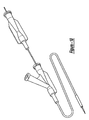
- Figure 6 is an exploded view of the medical device delivery system components;
- Figures 7-9 are partial cross-sectional views of a distal end portion of the medical device delivery system of Figure 2, corresponding to various operating configurations;
- Figure 10 is an external perspective view of a known medical device delivery system;
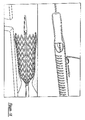
- Figures 11-14 are perspective views of proximal and distal ends of a medical device delivery system arranged according to the principles of the present invention, in various operating configurations; and
- Figure 15 is a diagrammatic example of a possible graph showing total resistive forces with respect to positional distance, of a medical device delivery system arranged according to the principles of the present invention.
-
- Referring to the drawings, a medical device delivery system is depicted, with one of the preferred embodiments of the present invention being shown at 10. The illustrated stent
delivery catheter system 10 of course depicts only one of many different medical device delivery systems designs that are contemplated. For clarity and convenience, the present detailed description will only describe such an example of a delivery system for stents. - One possible medical device delivery system that may be used with the present invention is any appropriate system in which an outer sheath is provided, surrounding an inner shaft. A medical device may be carried within the outer sheath during delivery to a desired site for treatment, where the outer sheath may be retracted, while the inner shaft and medical device are held in place.
- The novel concept of the present invention may also be used for medical device delivery systems in which the motion of the operator to deploy the medical device is selected from any suitable possibility, including axial motion in the proximal direction or the distal direction, or a rotational motion, a trigger actuator, a gear mechanism, or any other type of actuator that may be preferred, depending upon a particular application. Indeed, the present unique concept may be used for medical device delivery systems in which the medical device is deployed in any suitable manner, including retracting an outer sheath in a proximal direction or a distal direction, or uncovering a medical device in various ways, including withdrawing portions of outer sheath members in proximal and distal directions, simultaneously or sequentially.
- The present invention may provide several advantages individually, or any combination of such advantages, including for example: (i) single-handed operation of the medical device delivery system; (ii) a mechanism providing leverage or mechanical advantage, to adjust or reduce the forces needed to operate the system; (iii) improved accuracy in positioning the medical device during deployment; (iv) a capability of holding the delivery system components in a fixed relative position during an intermediate point in deploying a medical device; and (v) multiple operational modes of operation, including for example a first mode of fine and precise control of the deployment process, and a second mode of rapid and easy deployment.
- The
particular embodiment 10 of the present invention selected for illustration in the drawings includes a handle, shown in detail in Figures 1-6. A first and secondmain body housing outer shaft members anchoring member 20, aproximal hub 22 with an actuator orknob 24 and a correspondingflush lumen tube 26 and valve 28, as well as a threadedbase member 30 and a rotatingfinger ring 32. - The
main body housings several gripping knurls 34 for providing a physician with a good gripping surface, alongitudinal slot 36 defining a channel for sliding themovable actuator 24 and limiting the extent of possible travel for theactuator 24 andproximal hub assembly 22, a side opening 38 through which a physician can operate the rotatingfinger ring 32, aproximal anchoring aperture 40 adapted to capture a portion of theanchoring member 20, adistal shaft aperture 42 through which the inner andouter shaft members main body housings main body housings finger ring 32 touches this shoulder 46 in an initial configuration, and rotation of the rotatingfinger ring 32 causes it to advance along threadedbase 30 and press on shoulder 46, resulting in very precise and sensitive withdrawing movement ofouter shaft member 18 in a proximal direction. - In the particular assembly shown in the drawings,
main body housings Anchor aperture 40 fixedly receivesanchor 20, which is affixed to the proximal end ofinner shaft member 16. A proximal end ofouter shaft member 18 is affixed toproximal hub 22, with a flexible strain relief 48 protecting the joint. In the preferred initial configuration,proximal hub 22 is affixed to threadedbase 30, which rotatably carries rotatingfinger ring 32, which bears on the shoulder 46 ofmain body housing 12. - The preferred dual operation of the present invention is accomplished by enabling movement of
outer shaft member 18 with respect toinner shaft member 16 in two ways. First, by rotating thefinger ring 32 to cause it to advance on threadedbase 30 and press against shoulder 46, such that the entire assembly of threadedbase 30,proximal hub 22 andouter shaft member 18 withdraw proximally with respect tomain body housing inner shaft member 16. Second, by simply graspingknob 24 and pulling or pushing it withinslot 36. The first method allows precise and sensitive adjustment, while the second method allows relatively large-scale and rapid movement. - At the distal end of the medical device delivery system, shown in detail in Figures 7-9, distal ends of the inner and
outer shaft members tubular capsule 52 affixed toouter shaft member 18. The distal end ofinner shaft member 16 may be provided with a flexible tapering distal tip 54. At least a proximalannular stop 56, and preferably also a distalannular ring 58, are affixed toinner shaft member 16. Thestop 56 andring 58, as well as a distal marker 60 that may be provided, are preferably radiopaque. - In addition, the
inner shaft member 16 assembly, includinganchor 20,inner shaft member 16 and distal tip 54, may preferably be provided with a through lumen adapted to receive aguidewire 62. - In operation, the medical
device delivery system 10 is advanced via a body passageway, preferably along aguidewire 62, until the stent 50 is located within a desired site for treatment. A physician gently rotates thefinger ring 32 to slightly pull backouter shaft member 18. At this point, a small portion of the stent 50 may expand slightly. The handle of the present invention comfortably holds thedelivery system 10 in this intermediate configuration, allowing the physician time and flexibility of procedure to selectively optimize the position of the stent 50 within the desired site. This precise adjustment of the position of the stent 50, before any portion of the stent 50 touches the body passage orvessel 64 in a manner that might inhibit further positional adjustment, is preferable. - When the physician is satisfied with the positioning, the
finger ring 32 may be further rotated to cause a distal end of the stent 50 to gently contact thevessel 64. When such contact occurs, and the stent is expanded sufficiently to independently hold its position, it is desirable to rapidly and completely withdraw theouter shaft member 18. To do so, the physician grasps theknob 24 and pulls it back alongslot 36. Theouter shaft member 18 may thus be withdrawn as quickly as the physician wishes. - Various materials may be selected for the components of the present invention, including any material having the desirable performance characteristics. In the particular embodiment shown in the drawings, the inner and
outer shaft members outer shaft member ring 58, marker 60 are preferably made of any biocompatible material that is strong and rigid, including for example stainless steel, platinum, tungsten, etc. The components of the handle of the present invention are preferably made of a material that is strong and rigid, including for example inflexible polycarbonates, or even some metal components. - Of course, features of the invention can be varied from the above description, for example in respect of sizes, materials, and designs.
Claims (8)
- A medical device delivery system for therapeutically treating a patient, comprising:an inner shaft, having proximal and distal ends;a tubular outer sheath, at least a portion of which surrounds a portion of the inner shaft member;a medical device within the outer sheath in an initial configuration;a handle operatively coupled with the inner shaft and the outer sheath;the handle having a first and second actuator for adjusting the relative positions of the inner shaft and the outer sheath, each of the first and second actuators providing a different amount of mechanical advantage between an input to one of the first and second actuators by a physician and a resulting relative position of the inner shaft and the outer sheath respectively.
- The medical device delivery system of claim 1, wherein one of the first and second actuators provides a mechanical advantage of 1:1.
- The medical device delivery system of claim 1, wherein the first actuator is adapted to rotate around a threaded base.
- The medical device delivery system of claim 1, wherein the second actuator is adapted to slide along a longitudinal slot defined by the handle.
- The medical device delivery system of claim 1, wherein on of the first and second actuators is formed as a lever.
- The medical device delivery system of claim 1, wherein the first actuator provides a mechanical advantage greater than 1:1, to facilitate an operator to overcome initial resistance to changing the initial relative position of the inner shaft and the outer sheath.
- The medical device delivery system of claim 1, wherein the handle and the first and second actuators can be operated by one hand.
- A handle for manipulating a medical device delivery system for therapeutically treating a patient, comprising:a housing;inner and outer shaft members, in which the inner shaft member is affixed to the housing, and the outer shaft member is movably coupled to the inner shaft member, such that the outer shaft member can be moved longitudinally with respect to the inner shaft member;first and second means for selectively moving the outer shaft member with respect to the inner shaft member, in which the first means is adapted for precise and sensitive adjustment of the position of the outer shaft member, and the second means is adapted for rapid and relatively large-scale movement of the outer shaft member.
Applications Claiming Priority (2)
| Application Number | Priority Date | Filing Date | Title |
|---|---|---|---|
| US09/975,873 US6939352B2 (en) | 2001-10-12 | 2001-10-12 | Handle deployment mechanism for medical device and method |
| US975873 | 2001-10-12 |
Publications (3)
| Publication Number | Publication Date |
|---|---|
| EP1302178A2 true EP1302178A2 (en) | 2003-04-16 |
| EP1302178A3 EP1302178A3 (en) | 2004-01-28 |
| EP1302178B1 EP1302178B1 (en) | 2006-03-22 |
Family
ID=25523517
Family Applications (1)
| Application Number | Title | Priority Date | Filing Date |
|---|---|---|---|
| EP02257071A Expired - Lifetime EP1302178B1 (en) | 2001-10-12 | 2002-10-11 | Handle deployment mechanism for medical device & method |
Country Status (6)
| Country | Link |
|---|---|
| US (1) | US6939352B2 (en) |
| EP (1) | EP1302178B1 (en) |
| JP (1) | JP4294289B2 (en) |
| AT (1) | ATE320776T1 (en) |
| CA (1) | CA2407997C (en) |
| DE (1) | DE60210021T2 (en) |
Cited By (42)
| Publication number | Priority date | Publication date | Assignee | Title |
|---|---|---|---|---|
| EP1380271A1 (en) | 2002-06-19 | 2004-01-14 | Cordis Corporation | Locking handle deployment mechanism for medical device |
| EP1440671A3 (en) * | 2003-01-24 | 2005-02-02 | Sorin Biomedica Cardio S.R.L. | An actuating device for catheters |
| WO2005039448A1 (en) * | 2003-10-09 | 2005-05-06 | Boston Scientific Limited | Medical device delivery system |
| WO2005067819A1 (en) * | 2004-01-05 | 2005-07-28 | Medtronic Vascular, Inc. | Integrated mechanical handle with quick slide mechanism |
| WO2007005799A1 (en) | 2005-06-30 | 2007-01-11 | Abbott Laboratories | Delivery system for a medical device |
| EP1902746A1 (en) | 2006-09-21 | 2008-03-26 | Cathrx Ltd | Catheter actuator |
| EP1803422B1 (en) * | 2005-12-29 | 2009-12-16 | Cordis Corporation | Adjustable and detached stent deployment device |
| WO2010005524A3 (en) * | 2008-06-30 | 2010-03-04 | Bolton Medical, Inc. | Abdominal aortic aneurysms: systems and methods of use |
| US7763063B2 (en) | 2003-09-03 | 2010-07-27 | Bolton Medical, Inc. | Self-aligning stent graft delivery system, kit, and method |
| US7780716B2 (en) | 2003-09-02 | 2010-08-24 | Abbott Laboratories | Delivery system for a medical device |
| US7794489B2 (en) | 2003-09-02 | 2010-09-14 | Abbott Laboratories | Delivery system for a medical device |
| GB2474252A (en) * | 2009-10-07 | 2011-04-13 | Cook William Europ | Rotating handle on introducer allowing retraction of stent trigger wire |
| US7935141B2 (en) | 2005-08-17 | 2011-05-03 | C. R. Bard, Inc. | Variable speed stent delivery system |
| US8007605B2 (en) | 2003-09-03 | 2011-08-30 | Bolton Medical, Inc. | Method of forming a non-circular stent |
| EP2363099A1 (en) * | 2010-03-01 | 2011-09-07 | Koven Technology Canada Inc. | Medical device delivery system |
| WO2011136939A1 (en) * | 2010-04-30 | 2011-11-03 | Medtronic Vasular Inc. | Stent graft delivery system |
| US20110270371A1 (en) * | 2010-04-30 | 2011-11-03 | Medtronic Vascular, Inc. | Stent graft Delivery System |
| WO2011143474A1 (en) * | 2010-05-14 | 2011-11-17 | Medtronic Vascular Inc. | Catheter handle for prosthesis delivery system |
| US8062345B2 (en) | 2003-09-03 | 2011-11-22 | Bolton Medical, Inc. | Delivery systems for delivering and deploying stent grafts |
| US8062344B2 (en) | 2001-04-30 | 2011-11-22 | Angiomed Gmbh & Co. Medizintechnik Kg | Variable speed self-expanding stent delivery system and luer locking connector |
| GB2491478A (en) * | 2011-06-03 | 2012-12-05 | Vascutek Ltd | Stent graft deployment apparatus |
| GB2491479A (en) * | 2011-06-03 | 2012-12-05 | Vascutek Ltd | Apparatus for implanting a tubular device |
| US8486128B2 (en) | 2003-09-02 | 2013-07-16 | Abbott Laboratories | Delivery system for a medical device |
| US8500789B2 (en) | 2007-07-11 | 2013-08-06 | C. R. Bard, Inc. | Device for catheter sheath retraction |
| US8500792B2 (en) | 2003-09-03 | 2013-08-06 | Bolton Medical, Inc. | Dual capture device for stent graft delivery system and method for capturing a stent graft |
| US8663305B2 (en) | 2010-04-20 | 2014-03-04 | Medtronic Vascular, Inc. | Retraction mechanism and method for graft cover retraction |
| EP2727564A1 (en) * | 2006-01-13 | 2014-05-07 | C. R. Bard, Inc. | Stent delivery system |
| US8998970B2 (en) | 2012-04-12 | 2015-04-07 | Bolton Medical, Inc. | Vascular prosthetic delivery device and method of use |
| US9078779B2 (en) | 2006-08-07 | 2015-07-14 | C. R. Bard, Inc. | Hand-held actuator device |
| US9101506B2 (en) | 2009-03-13 | 2015-08-11 | Bolton Medical, Inc. | System and method for deploying an endoluminal prosthesis at a surgical site |
| US9326872B2 (en) | 2010-08-17 | 2016-05-03 | W. L. Gore & Associates, Inc. | Forced deployment sequence handle assembly with independent actuating mechanism |
| US9439751B2 (en) | 2013-03-15 | 2016-09-13 | Bolton Medical, Inc. | Hemostasis valve and delivery systems |
| US9717614B2 (en) | 2014-02-16 | 2017-08-01 | Cook Medical Technologies Llc | Deployment handle for a prosthesis delivery device |
| US9801745B2 (en) | 2010-10-21 | 2017-10-31 | C.R. Bard, Inc. | System to deliver a bodily implant |
| US9877857B2 (en) | 2003-09-03 | 2018-01-30 | Bolton Medical, Inc. | Sheath capture device for stent graft delivery system and method for operating same |
| US9949750B2 (en) | 2011-10-31 | 2018-04-24 | Boston Scientific Scimed, Inc. | Rotatable medical device |
| KR20190091478A (en) * | 2016-12-30 | 2019-08-06 | 세븐 썬즈 리미티드 알.엔. 515985570 (더 "컴퍼니") | Device and method for safely positioning a coronary stent in a coronary artery |
| US10646365B2 (en) | 2003-09-03 | 2020-05-12 | Bolton Medical, Inc. | Delivery system and method for self-centering a proximal end of a stent graft |
| EP3679889A1 (en) * | 2019-01-14 | 2020-07-15 | Cook Medical Technologies LLC | Multipurpose handle |
| US11026822B2 (en) | 2006-01-13 | 2021-06-08 | C. R. Bard, Inc. | Stent delivery system |
| US11259945B2 (en) | 2003-09-03 | 2022-03-01 | Bolton Medical, Inc. | Dual capture device for stent graft delivery system and method for capturing a stent graft |
| US11596537B2 (en) | 2003-09-03 | 2023-03-07 | Bolton Medical, Inc. | Delivery system and method for self-centering a proximal end of a stent graft |
Families Citing this family (203)
| Publication number | Priority date | Publication date | Assignee | Title |
|---|---|---|---|---|
| US7018401B1 (en) | 1999-02-01 | 2006-03-28 | Board Of Regents, The University Of Texas System | Woven intravascular devices and methods for making the same and apparatus for delivery of the same |
| CN1447669A (en) | 2000-08-18 | 2003-10-08 | 阿特里泰克公司 | Expandable implant devices for filtering blood flow from atrial appendages |
| US6743210B2 (en) * | 2001-02-15 | 2004-06-01 | Scimed Life Systems, Inc. | Stent delivery catheter positioning device |
| GB0110551D0 (en) * | 2001-04-30 | 2001-06-20 | Angiomed Ag | Self-expanding stent delivery service |
| GB0114939D0 (en) * | 2001-06-19 | 2001-08-08 | Angiomed Ag | Luer connector portion |
| WO2003003944A2 (en) | 2001-07-06 | 2003-01-16 | Angiomed Gmbh & Co. Medizintechnik Kg | Delivery system having a rapid pusher assembly for self-expanding stent, and stent exchange configuration |
| GB0123633D0 (en) | 2001-10-02 | 2001-11-21 | Angiomed Ag | Stent delivery system |
| US9561123B2 (en) | 2002-08-30 | 2017-02-07 | C.R. Bard, Inc. | Highly flexible stent and method of manufacture |
| US6878162B2 (en) | 2002-08-30 | 2005-04-12 | Edwards Lifesciences Ag | Helical stent having improved flexibility and expandability |
| US8568467B2 (en) | 2003-01-15 | 2013-10-29 | Angiomed Gmbh & Co. Medizintechnik Kg | Trans-luminal surgical device |
| US9861346B2 (en) | 2003-07-14 | 2018-01-09 | W. L. Gore & Associates, Inc. | Patent foramen ovale (PFO) closure device with linearly elongating petals |
| US9526609B2 (en) | 2003-12-23 | 2016-12-27 | Boston Scientific Scimed, Inc. | Methods and apparatus for endovascularly replacing a patient's heart valve |
| US11278398B2 (en) | 2003-12-23 | 2022-03-22 | Boston Scientific Scimed, Inc. | Methods and apparatus for endovascular heart valve replacement comprising tissue grasping elements |
| US8840663B2 (en) | 2003-12-23 | 2014-09-23 | Sadra Medical, Inc. | Repositionable heart valve method |
| US7445631B2 (en) | 2003-12-23 | 2008-11-04 | Sadra Medical, Inc. | Methods and apparatus for endovascularly replacing a patient's heart valve |
| US8182528B2 (en) | 2003-12-23 | 2012-05-22 | Sadra Medical, Inc. | Locking heart valve anchor |
| US20120041550A1 (en) | 2003-12-23 | 2012-02-16 | Sadra Medical, Inc. | Methods and Apparatus for Endovascular Heart Valve Replacement Comprising Tissue Grasping Elements |
| US7780725B2 (en) | 2004-06-16 | 2010-08-24 | Sadra Medical, Inc. | Everting heart valve |
| US8951299B2 (en) | 2003-12-23 | 2015-02-10 | Sadra Medical, Inc. | Medical devices and delivery systems for delivering medical devices |
| US8343213B2 (en) | 2003-12-23 | 2013-01-01 | Sadra Medical, Inc. | Leaflet engagement elements and methods for use thereof |
| US7381219B2 (en) | 2003-12-23 | 2008-06-03 | Sadra Medical, Inc. | Low profile heart valve and delivery system |
| US8603160B2 (en) | 2003-12-23 | 2013-12-10 | Sadra Medical, Inc. | Method of using a retrievable heart valve anchor with a sheath |
| US7959666B2 (en) | 2003-12-23 | 2011-06-14 | Sadra Medical, Inc. | Methods and apparatus for endovascularly replacing a heart valve |
| US8828078B2 (en) | 2003-12-23 | 2014-09-09 | Sadra Medical, Inc. | Methods and apparatus for endovascular heart valve replacement comprising tissue grasping elements |
| US20050137687A1 (en) | 2003-12-23 | 2005-06-23 | Sadra Medical | Heart valve anchor and method |
| US20050137694A1 (en) | 2003-12-23 | 2005-06-23 | Haug Ulrich R. | Methods and apparatus for endovascularly replacing a patient's heart valve |
| US8579962B2 (en) | 2003-12-23 | 2013-11-12 | Sadra Medical, Inc. | Methods and apparatus for performing valvuloplasty |
| US9005273B2 (en) | 2003-12-23 | 2015-04-14 | Sadra Medical, Inc. | Assessing the location and performance of replacement heart valves |
| US20050154439A1 (en) * | 2004-01-08 | 2005-07-14 | Gunderson Richard C. | Medical device delivery systems |
| JP5016310B2 (en) * | 2004-01-08 | 2012-09-05 | メリット・メディカル・システムズ・インコーポレイテッド | Handle and method of use of implantable device delivery system |
| US20060063973A1 (en) | 2004-04-21 | 2006-03-23 | Acclarent, Inc. | Methods and apparatus for treating disorders of the ear, nose and throat |
| US20070167682A1 (en) | 2004-04-21 | 2007-07-19 | Acclarent, Inc. | Endoscopic methods and devices for transnasal procedures |
| US7763067B2 (en) | 2004-09-01 | 2010-07-27 | C. R. Bard, Inc. | Stent and method for manufacturing the stent |
| DE102005003632A1 (en) | 2005-01-20 | 2006-08-17 | Fraunhofer-Gesellschaft zur Förderung der angewandten Forschung e.V. | Catheter for the transvascular implantation of heart valve prostheses |
| US7740636B2 (en) * | 2005-04-15 | 2010-06-22 | Abbott Medical Optics Inc. | Multi-action device for inserting an intraocular lens into an eye |
| US7962208B2 (en) | 2005-04-25 | 2011-06-14 | Cardiac Pacemakers, Inc. | Method and apparatus for pacing during revascularization |
| WO2006124822A1 (en) | 2005-05-13 | 2006-11-23 | Alveolus, Inc. | Delivery device allowing visual inspection of an intravascular site |
| JP5006317B2 (en) | 2005-07-06 | 2012-08-22 | バスキュラー・パスウェイズ・インコーポレイテッド | Intravenous catheter insertion device and method of using the same |
| US8968379B2 (en) * | 2005-09-02 | 2015-03-03 | Medtronic Vascular, Inc. | Stent delivery system with multiple evenly spaced pullwires |
| US20070213813A1 (en) | 2005-12-22 | 2007-09-13 | Symetis Sa | Stent-valves for valve replacement and associated methods and systems for surgery |
| EP1965730A4 (en) | 2005-12-30 | 2009-06-17 | Bard Inc C R | Stent with bio-resorbable connector and methods |
| CA2948428C (en) | 2006-02-14 | 2020-06-30 | Angiomed Gmbh & Co. Medizintechnik Kg | Highly flexible stent and method of manufacture |
| EP1988851A2 (en) | 2006-02-14 | 2008-11-12 | Sadra Medical, Inc. | Systems and methods for delivering a medical implant |
| US20090270840A1 (en) * | 2008-03-28 | 2009-10-29 | Coherex Medical, Inc. | Delivery systems for a medical device and related methods |
| US8529597B2 (en) | 2006-08-09 | 2013-09-10 | Coherex Medical, Inc. | Devices for reducing the size of an internal tissue opening |
| US8840655B2 (en) * | 2006-08-09 | 2014-09-23 | Coherex Medical, Inc. | Systems and devices for reducing the size of an internal tissue opening |
| US9138208B2 (en) | 2006-08-09 | 2015-09-22 | Coherex Medical, Inc. | Devices for reducing the size of an internal tissue opening |
| ES2382364T3 (en) * | 2006-09-28 | 2012-06-07 | St George Medical Inc | Thoracic aortic aneurysm repair device. |
| KR20130095317A (en) * | 2006-10-22 | 2013-08-27 | 이데브 테크놀로지스, 아이엔씨. | Devices and methods for stent advancement |
| EP3150177B1 (en) | 2006-10-22 | 2021-06-02 | Idev Technologies, Inc. | Methods for securing strand ends and the resulting devices |
| US20080140175A1 (en) | 2006-12-07 | 2008-06-12 | Boucher Donald D | Spring stop for stent delivery system and delivery system provided with same |
| EP4005537A1 (en) | 2007-02-12 | 2022-06-01 | C.R. Bard Inc. | Highly flexible stent and method of manufacture |
| US8333799B2 (en) * | 2007-02-12 | 2012-12-18 | C. R. Bard, Inc. | Highly flexible stent and method of manufacture |
| WO2008124603A1 (en) | 2007-04-05 | 2008-10-16 | Nmt Medical, Inc. | Septal closure device with centering mechanism |
| US7896915B2 (en) | 2007-04-13 | 2011-03-01 | Jenavalve Technology, Inc. | Medical device for treating a heart valve insufficiency |
| US8721546B2 (en) | 2007-05-07 | 2014-05-13 | Vascular Pathways, Inc. | Intravenous catheter insertion and blood sample devices and method of use |
| US9149379B2 (en) * | 2007-07-16 | 2015-10-06 | Cook Medical Technologies Llc | Delivery device |
| AU2009205739B2 (en) | 2008-01-16 | 2014-09-25 | St. Jude Medical, Inc. | Delivery and retrieval systems for collapsible/expandable prosthetic heart valves |
| US20090210046A1 (en) * | 2008-02-20 | 2009-08-20 | Abbott Laboratories | Handle assembly for a delivery system |
| US9044318B2 (en) | 2008-02-26 | 2015-06-02 | Jenavalve Technology Gmbh | Stent for the positioning and anchoring of a valvular prosthesis |
| BR112012021347A2 (en) | 2008-02-26 | 2019-09-24 | Jenavalve Tecnology Inc | stent for positioning and anchoring a valve prosthesis at an implantation site in a patient's heart |
| US20130165967A1 (en) | 2008-03-07 | 2013-06-27 | W.L. Gore & Associates, Inc. | Heart occlusion devices |
| US9474546B1 (en) | 2008-04-18 | 2016-10-25 | Advanced Bionics Ag | Pre-curved electrode array insertion tools |
| US9061119B2 (en) * | 2008-05-09 | 2015-06-23 | Edwards Lifesciences Corporation | Low profile delivery system for transcatheter heart valve |
| GB0810749D0 (en) | 2008-06-11 | 2008-07-16 | Angiomed Ag | Catherter delivery device |
| US9750625B2 (en) | 2008-06-11 | 2017-09-05 | C.R. Bard, Inc. | Catheter delivery device |
| EP2293838B1 (en) | 2008-07-01 | 2012-08-08 | Endologix, Inc. | Catheter system |
| US7976574B2 (en) * | 2008-08-08 | 2011-07-12 | Advanced Cardiovascular Systems, Inc. | Delivery system with variable delivery rate for deploying a medical device |
| DK2313032T3 (en) * | 2008-08-19 | 2021-02-15 | Merit Medical Systems Inc | SUPPLY DEVICE WITH A PROTECTIVE ELEMENT |
| CN103623498B (en) * | 2008-09-18 | 2015-12-30 | 阿克拉伦特公司 | Be used for the treatment of the method and apparatus of otorhinolaryngology disease |
| EP3360517B1 (en) * | 2008-12-30 | 2021-06-16 | Cook Medical Technologies LLC | Delivery device |
| US8876807B2 (en) | 2009-01-19 | 2014-11-04 | W. L. Gore & Associates, Inc. | Forced deployment sequence |
| US8858610B2 (en) * | 2009-01-19 | 2014-10-14 | W. L. Gore & Associates, Inc. | Forced deployment sequence |
| AU2009200350B1 (en) * | 2009-02-02 | 2009-07-16 | Cook Incorporated | Preloaded stent graft delivery device |
| US8858613B2 (en) | 2010-09-20 | 2014-10-14 | Altura Medical, Inc. | Stent graft delivery systems and associated methods |
| US8956389B2 (en) | 2009-06-22 | 2015-02-17 | W. L. Gore & Associates, Inc. | Sealing device and delivery system |
| US9381006B2 (en) | 2009-06-22 | 2016-07-05 | W. L. Gore & Associates, Inc. | Sealing device and delivery system |
| US20120029556A1 (en) | 2009-06-22 | 2012-02-02 | Masters Steven J | Sealing device and delivery system |
| EP2451366B1 (en) | 2009-07-08 | 2017-03-15 | Advanced Bionics AG | Lead insertion tools |
| EP2559404A3 (en) | 2009-12-01 | 2014-10-29 | Altura Medical, Inc. | Modular endograft devices and associated systems and methods |
| AU2011210747B2 (en) * | 2010-01-29 | 2013-06-13 | Cook Medical Technologies Llc | Mechanically expandable delivery and dilation systems |
| US11925779B2 (en) | 2010-05-14 | 2024-03-12 | C. R. Bard, Inc. | Catheter insertion device including top-mounted advancement components |
| US9872971B2 (en) | 2010-05-14 | 2018-01-23 | C. R. Bard, Inc. | Guidewire extension system for a catheter placement device |
| US8932258B2 (en) | 2010-05-14 | 2015-01-13 | C. R. Bard, Inc. | Catheter placement device and method |
| US9950139B2 (en) | 2010-05-14 | 2018-04-24 | C. R. Bard, Inc. | Catheter placement device including guidewire and catheter control elements |
| US10384039B2 (en) | 2010-05-14 | 2019-08-20 | C. R. Bard, Inc. | Catheter insertion device including top-mounted advancement components |
| MX341401B (en) * | 2010-05-14 | 2016-08-18 | Bard Inc C R | Catheter placement device and method. |
| CN103002833B (en) | 2010-05-25 | 2016-05-11 | 耶拿阀门科技公司 | Artificial heart valve and comprise artificial heart valve and support through conduit carry interior prosthese |
| US9023095B2 (en) | 2010-05-27 | 2015-05-05 | Idev Technologies, Inc. | Stent delivery system with pusher assembly |
| US8753352B2 (en) | 2010-06-25 | 2014-06-17 | Advanced Bionics Ag | Tools, systems, and methods for inserting a pre-curved electrode array portion of a lead into a bodily orifice |
| US8753353B2 (en) | 2010-06-25 | 2014-06-17 | Advanced Bionics Ag | Tools, systems, and methods for inserting an electrode array portion of a lead into a bodily orifice |
| US8774944B2 (en) | 2010-06-25 | 2014-07-08 | Advanced Bionics Ag | Tools, systems, and methods for inserting an electrode array portion of a lead into a bodily orifice |
| WO2012015782A1 (en) | 2010-07-30 | 2012-02-02 | Cook Medical Technologies Llc | Controlled release and recapture prosthetic deployment device |
| US9198788B2 (en) | 2010-09-01 | 2015-12-01 | Medtronic, Inc. | Single handed deployment handle |
| CN106073946B (en) | 2010-09-10 | 2022-01-04 | 西美蒂斯股份公司 | Valve replacement device, delivery device for a valve replacement device and method of producing a valve replacement device |
| CN103298432B (en) | 2010-11-17 | 2016-03-02 | 波士顿科学西美德公司 | stent delivery system |
| WO2012068389A1 (en) | 2010-11-17 | 2012-05-24 | Boston Scientific Scimed, Inc. | Stent delivery system |
| CN103298433B (en) | 2010-11-17 | 2016-03-16 | 波士顿科学西美德公司 | Stent delivery system and the Lock Part for using together with stent delivery system |
| WO2012078794A1 (en) | 2010-12-07 | 2012-06-14 | Merit Medical Systems, Inc. | Stent delivery systems and methods |
| US8690833B2 (en) | 2011-01-31 | 2014-04-08 | Vascular Pathways, Inc. | Intravenous catheter and insertion device with reduced blood spatter |
| EP3563898B1 (en) | 2011-02-25 | 2020-11-11 | C.R. Bard, Inc. | Medical component insertion device including a retractable needle |
| US8808350B2 (en) | 2011-03-01 | 2014-08-19 | Endologix, Inc. | Catheter system and methods of using same |
| US9744033B2 (en) | 2011-04-01 | 2017-08-29 | W.L. Gore & Associates, Inc. | Elastomeric leaflet for prosthetic heart valves |
| EP2520251A1 (en) | 2011-05-05 | 2012-11-07 | Symetis SA | Method and Apparatus for Compressing Stent-Valves |
| USD903101S1 (en) | 2011-05-13 | 2020-11-24 | C. R. Bard, Inc. | Catheter |
| US10117765B2 (en) | 2011-06-14 | 2018-11-06 | W.L. Gore Associates, Inc | Apposition fiber for use in endoluminal deployment of expandable implants |
| US9913741B2 (en) | 2011-07-05 | 2018-03-13 | Cook Medical Technologies Llc | Control handle for self-expandable medical devices |
| WO2013009975A1 (en) | 2011-07-12 | 2013-01-17 | Boston Scientific Scimed, Inc. | Coupling system for medical devices |
| US9770232B2 (en) | 2011-08-12 | 2017-09-26 | W. L. Gore & Associates, Inc. | Heart occlusion devices |
| US9554806B2 (en) | 2011-09-16 | 2017-01-31 | W. L. Gore & Associates, Inc. | Occlusive devices |
| US9526645B2 (en) | 2011-10-31 | 2016-12-27 | Merit Medical Systems, Inc. | Safety mechanism for an implantable device deployment apparatus |
| WO2013067168A1 (en) | 2011-11-02 | 2013-05-10 | Boston Scientific Scimed, Inc. | Stent delivery systems and methods for use |
| US9877858B2 (en) | 2011-11-14 | 2018-01-30 | W. L. Gore & Associates, Inc. | External steerable fiber for use in endoluminal deployment of expandable devices |
| US9782282B2 (en) | 2011-11-14 | 2017-10-10 | W. L. Gore & Associates, Inc. | External steerable fiber for use in endoluminal deployment of expandable devices |
| US8951243B2 (en) | 2011-12-03 | 2015-02-10 | Boston Scientific Scimed, Inc. | Medical device handle |
| US10172708B2 (en) | 2012-01-25 | 2019-01-08 | Boston Scientific Scimed, Inc. | Valve assembly with a bioabsorbable gasket and a replaceable valve implant |
| US9375308B2 (en) | 2012-03-13 | 2016-06-28 | W. L. Gore & Associates, Inc. | External steerable fiber for use in endoluminal deployment of expandable devices |
| JP6174841B2 (en) * | 2012-03-15 | 2017-08-02 | 株式会社カネカ | Controller and catheter kit |
| US9883941B2 (en) | 2012-06-19 | 2018-02-06 | Boston Scientific Scimed, Inc. | Replacement heart valve |
| AU2013299425A1 (en) | 2012-08-10 | 2015-03-19 | Altura Medical, Inc. | Stent delivery systems and associated methods |
| US10828019B2 (en) | 2013-01-18 | 2020-11-10 | W.L. Gore & Associates, Inc. | Sealing device and delivery system |
| CN105102054B (en) | 2013-01-30 | 2018-04-20 | 血管通路股份有限公司 | The system and method placed for venipuncture and conduit |
| US9308108B2 (en) | 2013-03-13 | 2016-04-12 | Cook Medical Technologies Llc | Controlled release and recapture stent-deployment device |
| WO2014144809A1 (en) | 2013-03-15 | 2014-09-18 | Altura Medical, Inc. | Endograft device delivery systems and associated methods |
| US11911258B2 (en) | 2013-06-26 | 2024-02-27 | W. L. Gore & Associates, Inc. | Space filling devices |
| US10085730B2 (en) | 2013-07-12 | 2018-10-02 | Phillips Medical, LLC | Hemostatic device and its methods of use |
| US9839416B2 (en) | 2013-07-12 | 2017-12-12 | Phillips Medical, LLC | Hemostatic device and its methods of use |
| US9974676B2 (en) | 2013-08-09 | 2018-05-22 | Cook Medical Technologies Llc | Wire collection device with geared advantage |
| US9974677B2 (en) | 2013-08-20 | 2018-05-22 | Cook Medical Technologies Llc | Wire collection device for stent delivery system |
| JP6563394B2 (en) | 2013-08-30 | 2019-08-21 | イェーナヴァルヴ テクノロジー インコーポレイテッド | Radially foldable frame for an artificial valve and method for manufacturing the frame |
| WO2015057195A1 (en) | 2013-10-15 | 2015-04-23 | Stryker Corporation | Device for creating a void space in a living tissue, the device including a handle with a control knob that can be set regardless of the orientation of the handle |
| US9974678B2 (en) | 2014-03-10 | 2018-05-22 | Cook Medical Technologies Llc | Wire collection device with varying collection diameter |
| US9833346B2 (en) | 2014-04-04 | 2017-12-05 | W. L. Gore & Associates, Inc. | Deployment handle for a medical device deployment system |
| US10016292B2 (en) | 2014-04-18 | 2018-07-10 | Covidien Lp | Stent delivery system |
| WO2015179140A1 (en) | 2014-05-21 | 2015-11-26 | Boston Scientific Scimed, Inc. | Stent delivery system |
| US9808230B2 (en) | 2014-06-06 | 2017-11-07 | W. L. Gore & Associates, Inc. | Sealing device and delivery system |
| US10232146B2 (en) | 2014-09-05 | 2019-03-19 | C. R. Bard, Inc. | Catheter insertion device including retractable needle |
| US10238845B2 (en) * | 2014-09-19 | 2019-03-26 | Acclarent, Inc. | Balloon catheter assembly |
| US9901445B2 (en) | 2014-11-21 | 2018-02-27 | Boston Scientific Scimed, Inc. | Valve locking mechanism |
| US10159587B2 (en) * | 2015-01-16 | 2018-12-25 | Boston Scientific Scimed, Inc. | Medical device delivery system with force reduction member |
| US10449043B2 (en) | 2015-01-16 | 2019-10-22 | Boston Scientific Scimed, Inc. | Displacement based lock and release mechanism |
| US9861477B2 (en) | 2015-01-26 | 2018-01-09 | Boston Scientific Scimed Inc. | Prosthetic heart valve square leaflet-leaflet stitch |
| US10201417B2 (en) | 2015-02-03 | 2019-02-12 | Boston Scientific Scimed Inc. | Prosthetic heart valve having tubular seal |
| US9788942B2 (en) | 2015-02-03 | 2017-10-17 | Boston Scientific Scimed Inc. | Prosthetic heart valve having tubular seal |
| US10285834B2 (en) | 2015-03-05 | 2019-05-14 | Merit Medical Systems, Inc. | Vascular prosthesis deployment device and method of use |
| US10426617B2 (en) | 2015-03-06 | 2019-10-01 | Boston Scientific Scimed, Inc. | Low profile valve locking mechanism and commissure assembly |
| US10285809B2 (en) | 2015-03-06 | 2019-05-14 | Boston Scientific Scimed Inc. | TAVI anchoring assist device |
| US10080652B2 (en) | 2015-03-13 | 2018-09-25 | Boston Scientific Scimed, Inc. | Prosthetic heart valve having an improved tubular seal |
| USD903100S1 (en) | 2015-05-01 | 2020-11-24 | C. R. Bard, Inc. | Catheter placement device |
| JP6767388B2 (en) | 2015-05-01 | 2020-10-14 | イェーナヴァルヴ テクノロジー インコーポレイテッド | Devices and methods to reduce the proportion of pacemakers in heart valve replacement |
| JP2018515246A (en) | 2015-05-14 | 2018-06-14 | ダブリュ.エル.ゴア アンド アソシエイツ,インコーポレイティドW.L. Gore & Associates, Incorporated | Devices and methods for atrial appendage occlusion |
| CA2985202C (en) | 2015-05-15 | 2023-10-10 | C.R. Bard, Inc. | Catheter placement device including an extensible needle safety component |
| JP2018524025A (en) | 2015-06-30 | 2018-08-30 | エンドロジックス、インク | Lock assembly for coupling guidewire to delivery system |
| US10335277B2 (en) | 2015-07-02 | 2019-07-02 | Boston Scientific Scimed Inc. | Adjustable nosecone |
| US10195392B2 (en) | 2015-07-02 | 2019-02-05 | Boston Scientific Scimed, Inc. | Clip-on catheter |
| US10136991B2 (en) | 2015-08-12 | 2018-11-27 | Boston Scientific Scimed Inc. | Replacement heart valve implant |
| US10179041B2 (en) | 2015-08-12 | 2019-01-15 | Boston Scientific Scimed Icn. | Pinless release mechanism |
| US10470906B2 (en) | 2015-09-15 | 2019-11-12 | Merit Medical Systems, Inc. | Implantable device delivery system |
| US11351048B2 (en) | 2015-11-16 | 2022-06-07 | Boston Scientific Scimed, Inc. | Stent delivery systems with a reinforced deployment sheath |
| AU2016355676B2 (en) | 2015-11-20 | 2018-12-13 | Cardiac Pacemakers, Inc. | Delivery devices and methods for leadless cardiac devices |
| EP3377174B1 (en) | 2015-11-20 | 2019-08-28 | Cardiac Pacemakers, Inc. | Delivery systems for leadless cardiac devices |
| JP6258914B2 (en) * | 2015-12-17 | 2018-01-10 | 株式会社カネカ | Controller, catheter kit, and method of using the controller |
| US10342660B2 (en) | 2016-02-02 | 2019-07-09 | Boston Scientific Inc. | Tensioned sheathing aids |
| EP3419568B1 (en) | 2016-02-26 | 2021-09-08 | Boston Scientific Scimed, Inc. | Stent delivery systems with a reduced profile |
| US10022255B2 (en) | 2016-04-11 | 2018-07-17 | Idev Technologies, Inc. | Stent delivery system having anisotropic sheath |
| US10583005B2 (en) | 2016-05-13 | 2020-03-10 | Boston Scientific Scimed, Inc. | Medical device handle |
| EP4183371A1 (en) | 2016-05-13 | 2023-05-24 | JenaValve Technology, Inc. | Heart valve prosthesis delivery system and method for delivery of heart valve prosthesis with introducer sheath and loading system |
| US10201416B2 (en) | 2016-05-16 | 2019-02-12 | Boston Scientific Scimed, Inc. | Replacement heart valve implant with invertible leaflets |
| SG11201901968TA (en) | 2016-09-12 | 2019-04-29 | Bard Inc C R | Blood control for a catheter insertion device |
| CN109789025B (en) | 2016-09-29 | 2022-06-10 | 美国医疗设备有限公司 | Compliant member for receiving and assisting deployment of vascular prostheses |
| WO2018138658A1 (en) | 2017-01-27 | 2018-08-02 | Jenavalve Technology, Inc. | Heart valve mimicry |
| US11400260B2 (en) | 2017-03-01 | 2022-08-02 | C. R. Bard, Inc. | Catheter insertion device |
| WO2018170066A1 (en) | 2017-03-15 | 2018-09-20 | Merit Medical Systems, Inc. | Transluminal delivery devices and related kits and methods |
| US10744009B2 (en) | 2017-03-15 | 2020-08-18 | Merit Medical Systems, Inc. | Transluminal stents and related methods |
| USD836194S1 (en) | 2017-03-21 | 2018-12-18 | Merit Medical Systems, Inc. | Stent deployment device |
| CN113143413B (en) | 2017-05-03 | 2022-06-21 | 美敦力瓦斯科尔勒公司 | Tissue removal catheter with guidewire isolation bushing |
| US11690645B2 (en) | 2017-05-03 | 2023-07-04 | Medtronic Vascular, Inc. | Tissue-removing catheter |
| US10828154B2 (en) | 2017-06-08 | 2020-11-10 | Boston Scientific Scimed, Inc. | Heart valve implant commissure support structure |
| WO2019028161A1 (en) | 2017-08-01 | 2019-02-07 | Boston Scientific Scimed, Inc. | Medical implant locking mechanism |
| US10939996B2 (en) | 2017-08-16 | 2021-03-09 | Boston Scientific Scimed, Inc. | Replacement heart valve commissure assembly |
| US10925763B2 (en) * | 2017-09-13 | 2021-02-23 | CARDINAL HEALTH SWITZERLAND 515 GmbH | Stent delivery catheter with convertible living-hinge for slow to fast retraction |
| US11173023B2 (en) | 2017-10-16 | 2021-11-16 | W. L. Gore & Associates, Inc. | Medical devices and anchors therefor |
| US11096810B2 (en) | 2017-11-29 | 2021-08-24 | Cook Medical Technologies Llc | Preloaded pusher tip for endografts |
| US11013627B2 (en) | 2018-01-10 | 2021-05-25 | Boston Scientific Scimed, Inc. | Stent delivery system with displaceable deployment mechanism |
| WO2019144071A1 (en) | 2018-01-19 | 2019-07-25 | Boston Scientific Scimed, Inc. | Medical device delivery system with feedback loop |
| WO2019144069A2 (en) | 2018-01-19 | 2019-07-25 | Boston Scientific Scimed, Inc. | Inductance mode deployment sensors for transcatheter valve system |
| US11147668B2 (en) | 2018-02-07 | 2021-10-19 | Boston Scientific Scimed, Inc. | Medical device delivery system with alignment feature |
| US11439732B2 (en) | 2018-02-26 | 2022-09-13 | Boston Scientific Scimed, Inc. | Embedded radiopaque marker in adaptive seal |
| US11389626B2 (en) | 2018-03-07 | 2022-07-19 | Bard Access Systems, Inc. | Guidewire advancement and blood flashback systems for a medical device insertion system |
| US11229517B2 (en) | 2018-05-15 | 2022-01-25 | Boston Scientific Scimed, Inc. | Replacement heart valve commissure assembly |
| US10441449B1 (en) | 2018-05-30 | 2019-10-15 | Vesper Medical, Inc. | Rotary handle stent delivery system and method |
| WO2019241477A1 (en) | 2018-06-13 | 2019-12-19 | Boston Scientific Scimed, Inc. | Replacement heart valve delivery device |
| USD921884S1 (en) | 2018-07-27 | 2021-06-08 | Bard Access Systems, Inc. | Catheter insertion device |
| US10449073B1 (en) | 2018-09-18 | 2019-10-22 | Vesper Medical, Inc. | Rotary handle stent delivery system and method |
| US11241312B2 (en) | 2018-12-10 | 2022-02-08 | Boston Scientific Scimed, Inc. | Medical device delivery system including a resistance member |
| JP7399971B2 (en) | 2019-02-13 | 2023-12-18 | ボストン サイエンティフィック サイムド,インコーポレイテッド | stent delivery system |
| US11849986B2 (en) | 2019-04-24 | 2023-12-26 | Stryker Corporation | Systems and methods for off-axis augmentation of a vertebral body |
| US11439504B2 (en) | 2019-05-10 | 2022-09-13 | Boston Scientific Scimed, Inc. | Replacement heart valve with improved cusp washout and reduced loading |
| US11819236B2 (en) | 2019-05-17 | 2023-11-21 | Medtronic Vascular, Inc. | Tissue-removing catheter |
| CN112386778A (en) | 2019-08-19 | 2021-02-23 | 贝克顿·迪金森公司 | Midline catheter placement device |
| US11219541B2 (en) | 2020-05-21 | 2022-01-11 | Vesper Medical, Inc. | Wheel lock for thumbwheel actuated device |
| US11839561B2 (en) | 2021-01-21 | 2023-12-12 | Inspire M.D Ltd. | Handle for two-stage deployment of a stent |
| CN113317878B (en) * | 2021-06-21 | 2022-06-10 | 哈尔滨理工大学 | Electrophysiology catheter robot |
Citations (3)
| Publication number | Priority date | Publication date | Assignee | Title |
|---|---|---|---|---|
| US4580568A (en) | 1984-10-01 | 1986-04-08 | Cook, Incorporated | Percutaneous endovascular stent and method for insertion thereof |
| US4732152A (en) | 1984-12-05 | 1988-03-22 | Medinvent S.A. | Device for implantation and a method of implantation in a vessel using such device |
| US6019778A (en) | 1998-03-13 | 2000-02-01 | Cordis Corporation | Delivery apparatus for a self-expanding stent |
Family Cites Families (33)
| Publication number | Priority date | Publication date | Assignee | Title |
|---|---|---|---|---|
| US4665918A (en) | 1986-01-06 | 1987-05-19 | Garza Gilbert A | Prosthesis system and method |
| SE8803444D0 (en) | 1988-09-28 | 1988-09-28 | Medinvent Sa | A DEVICE FOR TRANSLUMINAL IMPLANTATION OR EXTRACTION |
| EP0408245B1 (en) | 1989-07-13 | 1994-03-02 | American Medical Systems, Inc. | Stent placement instrument |
| CA2060067A1 (en) | 1991-01-28 | 1992-07-29 | Lilip Lau | Stent delivery system |
| US5591172A (en) * | 1991-06-14 | 1997-01-07 | Ams Medinvent S.A. | Transluminal implantation device |
| EP0536610B1 (en) * | 1991-10-11 | 1997-09-03 | Angiomed GmbH & Co. Medizintechnik KG | Stenosis dilatation device |
| US5290310A (en) * | 1991-10-30 | 1994-03-01 | Howmedica, Inc. | Hemostatic implant introducer |
| US5707376A (en) | 1992-08-06 | 1998-01-13 | William Cook Europe A/S | Stent introducer and method of use |
| US5312351A (en) * | 1993-01-29 | 1994-05-17 | Gerrone Carmen J | Combined pneumo-needle and trocar apparatus |
| US5391172A (en) | 1993-05-24 | 1995-02-21 | Advanced Cardiovascular Systems, Inc. | Stent delivery system with coaxial catheter handle |
| FR2718345B1 (en) * | 1994-04-11 | 1997-04-04 | Braun Celsa Sa | Handle for controlled relative sliding of a sheath and a rod and apparatus for implanting a medical device, such as a filter, using such a handle. |
| US5749921A (en) * | 1996-02-20 | 1998-05-12 | Medtronic, Inc. | Apparatus and methods for compression of endoluminal prostheses |
| US5704914A (en) * | 1996-02-23 | 1998-01-06 | Stocking; John E. | Catheter placement assembly |
| EP0864195B1 (en) | 1996-09-10 | 2002-02-27 | Koninklijke Philips Electronics N.V. | Battery-powered electrical device |
| DE69726317T2 (en) * | 1996-09-18 | 2004-09-16 | Micro Therapeutics, Inc., Irvine | INTRACRANIAL STENT |
| US5968052A (en) | 1996-11-27 | 1999-10-19 | Scimed Life Systems Inc. | Pull back stent delivery system with pistol grip retraction handle |
| US5776142A (en) * | 1996-12-19 | 1998-07-07 | Medtronic, Inc. | Controllable stent delivery system and method |
| US5868755A (en) | 1997-01-16 | 1999-02-09 | Atrion Medical Products, Inc. | Sheath retractor mechanism and method |
| US5891154A (en) | 1997-05-06 | 1999-04-06 | Advanced Cardiovascular System, Inc. | Passive perfusion stent delivery system |
| US5906619A (en) * | 1997-07-24 | 1999-05-25 | Medtronic, Inc. | Disposable delivery device for endoluminal prostheses |
| US6143021A (en) | 1998-07-10 | 2000-11-07 | American Medical Systems, Inc. | Stent placement instrument and method of assembly |
| US5944727A (en) | 1998-09-02 | 1999-08-31 | Datascope Investment Corp. | Stent/graft catheter handle |
| US6093194A (en) | 1998-09-14 | 2000-07-25 | Endocare, Inc. | Insertion device for stents and methods for use |
| ES2237168T3 (en) | 1998-09-30 | 2005-07-16 | Bard Peripheral Vascular, Inc. | SUPPLY MECHANISM FOR IMPLANTABLE STENT. |
| US6203550B1 (en) * | 1998-09-30 | 2001-03-20 | Medtronic, Inc. | Disposable delivery device for endoluminal prostheses |
| US7025773B2 (en) | 1999-01-15 | 2006-04-11 | Medtronic, Inc. | Methods and devices for placing a conduit in fluid communication with a target vessel |
| US6190360B1 (en) | 1999-04-09 | 2001-02-20 | Endotex Interventional System | Stent delivery handle |
| US6146415A (en) | 1999-05-07 | 2000-11-14 | Advanced Cardiovascular Systems, Inc. | Stent delivery system |
| US6375676B1 (en) | 1999-05-17 | 2002-04-23 | Advanced Cardiovascular Systems, Inc. | Self-expanding stent with enhanced delivery precision and stent delivery system |
| FR2797761B1 (en) * | 1999-08-24 | 2002-03-22 | Novatech Inc | DEVICE FOR PROVIDING RELEASE IN A HUMAN OR ANIMAL CONDUIT OF AN OBJECT, IN PARTICULAR A PROSTHESIS, AND IMPLANTATION SYSTEM COMPRISING A CATHETER AND SUCH A DEVICE |
| FR2797781B1 (en) | 1999-08-27 | 2002-11-08 | Patrick Duhaut | SEMI-PERMEABLE MEMBRANE DRYING PROCESS |
| US6613014B1 (en) | 2000-06-09 | 2003-09-02 | Advanced Cardiovascular Systems, Inc. | Catheter hub with detachable push device |
| GB0110551D0 (en) | 2001-04-30 | 2001-06-20 | Angiomed Ag | Self-expanding stent delivery service |
-
2001
- 2001-10-12 US US09/975,873 patent/US6939352B2/en not_active Expired - Lifetime
-
2002
- 2002-10-11 AT AT02257071T patent/ATE320776T1/en not_active IP Right Cessation
- 2002-10-11 EP EP02257071A patent/EP1302178B1/en not_active Expired - Lifetime
- 2002-10-11 DE DE60210021T patent/DE60210021T2/en not_active Expired - Lifetime
- 2002-10-11 JP JP2002299330A patent/JP4294289B2/en not_active Expired - Lifetime
- 2002-10-15 CA CA2407997A patent/CA2407997C/en not_active Expired - Lifetime
Patent Citations (3)
| Publication number | Priority date | Publication date | Assignee | Title |
|---|---|---|---|---|
| US4580568A (en) | 1984-10-01 | 1986-04-08 | Cook, Incorporated | Percutaneous endovascular stent and method for insertion thereof |
| US4732152A (en) | 1984-12-05 | 1988-03-22 | Medinvent S.A. | Device for implantation and a method of implantation in a vessel using such device |
| US6019778A (en) | 1998-03-13 | 2000-02-01 | Cordis Corporation | Delivery apparatus for a self-expanding stent |
Cited By (116)
| Publication number | Priority date | Publication date | Assignee | Title |
|---|---|---|---|---|
| US8062344B2 (en) | 2001-04-30 | 2011-11-22 | Angiomed Gmbh & Co. Medizintechnik Kg | Variable speed self-expanding stent delivery system and luer locking connector |
| US7105016B2 (en) | 2002-04-23 | 2006-09-12 | Medtronic Vascular, Inc. | Integrated mechanical handle with quick slide mechanism |
| US7419501B2 (en) | 2002-04-23 | 2008-09-02 | Medtronic Vascular, Inc. | Integrated mechanical handle with quick slide mechanism |
| EP1380271A1 (en) | 2002-06-19 | 2004-01-14 | Cordis Corporation | Locking handle deployment mechanism for medical device |
| EP1440671A3 (en) * | 2003-01-24 | 2005-02-02 | Sorin Biomedica Cardio S.R.L. | An actuating device for catheters |
| US7278998B2 (en) | 2003-01-24 | 2007-10-09 | Sorin Biomedica Cardio S.R.L. | Actuating device for catheters |
| US7780716B2 (en) | 2003-09-02 | 2010-08-24 | Abbott Laboratories | Delivery system for a medical device |
| US8486128B2 (en) | 2003-09-02 | 2013-07-16 | Abbott Laboratories | Delivery system for a medical device |
| US8382813B2 (en) | 2003-09-02 | 2013-02-26 | Abbott Laboratories | Delivery system for a medical device |
| US7799065B2 (en) | 2003-09-02 | 2010-09-21 | Abbott Laboratories | Delivery system for a medical device |
| US7794489B2 (en) | 2003-09-02 | 2010-09-14 | Abbott Laboratories | Delivery system for a medical device |
| US9220617B2 (en) | 2003-09-03 | 2015-12-29 | Bolton Medical, Inc. | Dual capture device for stent graft delivery system and method for capturing a stent graft |
| US10646365B2 (en) | 2003-09-03 | 2020-05-12 | Bolton Medical, Inc. | Delivery system and method for self-centering a proximal end of a stent graft |
| US11813158B2 (en) | 2003-09-03 | 2023-11-14 | Bolton Medical, Inc. | Stent graft delivery device |
| US9655712B2 (en) | 2003-09-03 | 2017-05-23 | Bolton Medical, Inc. | Vascular repair devices |
| US9333104B2 (en) | 2003-09-03 | 2016-05-10 | Bolton Medical, Inc. | Delivery systems for delivering and deploying stent grafts |
| US11596537B2 (en) | 2003-09-03 | 2023-03-07 | Bolton Medical, Inc. | Delivery system and method for self-centering a proximal end of a stent graft |
| US9320631B2 (en) | 2003-09-03 | 2016-04-26 | Bolton Medical, Inc. | Aligning device for stent graft delivery system |
| US9408734B2 (en) | 2003-09-03 | 2016-08-09 | Bolton Medical, Inc. | Methods of implanting a prosthesis |
| US8007605B2 (en) | 2003-09-03 | 2011-08-30 | Bolton Medical, Inc. | Method of forming a non-circular stent |
| US11413173B2 (en) | 2003-09-03 | 2022-08-16 | Bolton Medical, Inc. | Stent graft with a longitudinal support member |
| US9408735B2 (en) | 2003-09-03 | 2016-08-09 | Bolton Medical, Inc. | Methods of implanting a prosthesis and treating an aneurysm |
| US11259945B2 (en) | 2003-09-03 | 2022-03-01 | Bolton Medical, Inc. | Dual capture device for stent graft delivery system and method for capturing a stent graft |
| US11103341B2 (en) | 2003-09-03 | 2021-08-31 | Bolton Medical, Inc. | Stent graft delivery device |
| US8062345B2 (en) | 2003-09-03 | 2011-11-22 | Bolton Medical, Inc. | Delivery systems for delivering and deploying stent grafts |
| US9198786B2 (en) | 2003-09-03 | 2015-12-01 | Bolton Medical, Inc. | Lumen repair device with capture structure |
| US8062349B2 (en) | 2003-09-03 | 2011-11-22 | Bolton Medical, Inc. | Method for aligning a stent graft delivery system |
| US8070790B2 (en) | 2003-09-03 | 2011-12-06 | Bolton Medical, Inc. | Capture device for stent graft delivery |
| US9173755B2 (en) | 2003-09-03 | 2015-11-03 | Bolton Medical, Inc. | Vascular repair devices |
| US8292943B2 (en) | 2003-09-03 | 2012-10-23 | Bolton Medical, Inc. | Stent graft with longitudinal support member |
| US8308790B2 (en) | 2003-09-03 | 2012-11-13 | Bolton Medical, Inc. | Two-part expanding stent graft delivery system |
| US9877857B2 (en) | 2003-09-03 | 2018-01-30 | Bolton Medical, Inc. | Sheath capture device for stent graft delivery system and method for operating same |
| US9907686B2 (en) | 2003-09-03 | 2018-03-06 | Bolton Medical, Inc. | System for implanting a prosthesis |
| US10945827B2 (en) | 2003-09-03 | 2021-03-16 | Bolton Medical, Inc. | Vascular repair devices |
| US9913743B2 (en) | 2003-09-03 | 2018-03-13 | Bolton Medical, Inc. | Methods of implanting a prosthesis and treating an aneurysm |
| US8449595B2 (en) | 2003-09-03 | 2013-05-28 | Bolton Medical, Inc. | Delivery systems for delivering and deploying stent grafts |
| US9925080B2 (en) | 2003-09-03 | 2018-03-27 | Bolton Medical, Inc. | Methods of implanting a prosthesis |
| US10918509B2 (en) | 2003-09-03 | 2021-02-16 | Bolton Medical, Inc. | Aligning device for stent graft delivery system |
| US9561124B2 (en) | 2003-09-03 | 2017-02-07 | Bolton Medical, Inc. | Methods of self-aligning stent grafts |
| US10105250B2 (en) | 2003-09-03 | 2018-10-23 | Bolton Medical, Inc. | Dual capture device for stent graft delivery system and method for capturing a stent graft |
| US8500792B2 (en) | 2003-09-03 | 2013-08-06 | Bolton Medical, Inc. | Dual capture device for stent graft delivery system and method for capturing a stent graft |
| US10390929B2 (en) | 2003-09-03 | 2019-08-27 | Bolton Medical, Inc. | Methods of self-aligning stent grafts |
| US7763063B2 (en) | 2003-09-03 | 2010-07-27 | Bolton Medical, Inc. | Self-aligning stent graft delivery system, kit, and method |
| US8636788B2 (en) | 2003-09-03 | 2014-01-28 | Bolton Medical, Inc. | Methods of implanting a prosthesis |
| US10213291B2 (en) | 2003-09-03 | 2019-02-26 | Bolto Medical, Inc. | Vascular repair devices |
| US10182930B2 (en) | 2003-09-03 | 2019-01-22 | Bolton Medical, Inc. | Aligning device for stent graft delivery system |
| US8740963B2 (en) | 2003-09-03 | 2014-06-03 | Bolton Medical, Inc. | Methods of implanting a prosthesis and treating an aneurysm |
| WO2005039448A1 (en) * | 2003-10-09 | 2005-05-06 | Boston Scientific Limited | Medical device delivery system |
| US7967829B2 (en) | 2003-10-09 | 2011-06-28 | Boston Scientific Scimed, Inc. | Medical device delivery system |
| WO2005067819A1 (en) * | 2004-01-05 | 2005-07-28 | Medtronic Vascular, Inc. | Integrated mechanical handle with quick slide mechanism |
| WO2007005799A1 (en) | 2005-06-30 | 2007-01-11 | Abbott Laboratories | Delivery system for a medical device |
| US7935141B2 (en) | 2005-08-17 | 2011-05-03 | C. R. Bard, Inc. | Variable speed stent delivery system |
| EP1803422B1 (en) * | 2005-12-29 | 2009-12-16 | Cordis Corporation | Adjustable and detached stent deployment device |
| US11026822B2 (en) | 2006-01-13 | 2021-06-08 | C. R. Bard, Inc. | Stent delivery system |
| US8808346B2 (en) | 2006-01-13 | 2014-08-19 | C. R. Bard, Inc. | Stent delivery system |
| US9675486B2 (en) | 2006-01-13 | 2017-06-13 | C.R. Bard, Inc. | Stent delivery system |
| EP2727564A1 (en) * | 2006-01-13 | 2014-05-07 | C. R. Bard, Inc. | Stent delivery system |
| US9078779B2 (en) | 2006-08-07 | 2015-07-14 | C. R. Bard, Inc. | Hand-held actuator device |
| EP1902746A1 (en) | 2006-09-21 | 2008-03-26 | Cathrx Ltd | Catheter actuator |
| US20080243115A1 (en) * | 2006-09-21 | 2008-10-02 | David Ogle | Catheter actuator |
| US8500789B2 (en) | 2007-07-11 | 2013-08-06 | C. R. Bard, Inc. | Device for catheter sheath retraction |
| US11026821B2 (en) | 2007-07-11 | 2021-06-08 | C. R. Bard, Inc. | Device for catheter sheath retraction |
| US9421115B2 (en) | 2007-07-11 | 2016-08-23 | C. R. Bard, Inc. | Device for catheter sheath retraction |
| US10206800B2 (en) | 2007-07-11 | 2019-02-19 | C.R. Bard, Inc. | Device for catheter sheath retraction |
| US10307275B2 (en) | 2008-06-30 | 2019-06-04 | Bolton Medical, Inc. | Abdominal aortic aneurysms: systems and methods of use |
| EP3219292A1 (en) * | 2008-06-30 | 2017-09-20 | Bolton Medical Inc. | Abdominal aortic aneurysms systems |
| WO2010005524A3 (en) * | 2008-06-30 | 2010-03-04 | Bolton Medical, Inc. | Abdominal aortic aneurysms: systems and methods of use |
| US10105248B2 (en) | 2008-06-30 | 2018-10-23 | Bolton Medical, Inc. | Abdominal aortic aneurysms: systems and methods of use |
| US11382779B2 (en) | 2008-06-30 | 2022-07-12 | Bolton Medical, Inc. | Abdominal aortic aneurysms: systems and methods of use |
| US10864097B2 (en) | 2008-06-30 | 2020-12-15 | Bolton Medical, Inc. | Abdominal aortic aneurysms: systems and methods of use |
| US9364314B2 (en) | 2008-06-30 | 2016-06-14 | Bolton Medical, Inc. | Abdominal aortic aneurysms: systems and methods of use |
| US9827123B2 (en) | 2009-03-13 | 2017-11-28 | Bolton Medical, Inc. | System for deploying an endoluminal prosthesis at a surgical site |
| US10898357B2 (en) | 2009-03-13 | 2021-01-26 | Bolton Medical, Inc. | System for deploying an endoluminal prosthesis at a surgical site |
| US9101506B2 (en) | 2009-03-13 | 2015-08-11 | Bolton Medical, Inc. | System and method for deploying an endoluminal prosthesis at a surgical site |
| GB2474252A (en) * | 2009-10-07 | 2011-04-13 | Cook William Europ | Rotating handle on introducer allowing retraction of stent trigger wire |
| GB2474252B (en) * | 2009-10-07 | 2012-01-25 | Cook Medical Technologies Llc | Deployment handle for an introducer |
| US8968380B2 (en) | 2009-10-07 | 2015-03-03 | Cook Medical Technologies Llc | Deployment handle for an introducer |
| US10278846B2 (en) | 2009-10-07 | 2019-05-07 | Cook Medical Technologies Llc | Deployment handle for an introducer |
| US11096811B2 (en) | 2009-10-07 | 2021-08-24 | Cook Medical Technologies Llc | Deployment handle for an introducer |
| EP2363099A1 (en) * | 2010-03-01 | 2011-09-07 | Koven Technology Canada Inc. | Medical device delivery system |
| US8663305B2 (en) | 2010-04-20 | 2014-03-04 | Medtronic Vascular, Inc. | Retraction mechanism and method for graft cover retraction |
| US8747448B2 (en) * | 2010-04-30 | 2014-06-10 | Medtronic Vascular, Inc. | Stent graft delivery system |
| US8623064B2 (en) | 2010-04-30 | 2014-01-07 | Medtronic Vascular, Inc. | Stent graft delivery system and method of use |
| WO2011136939A1 (en) * | 2010-04-30 | 2011-11-03 | Medtronic Vasular Inc. | Stent graft delivery system |
| US20110270371A1 (en) * | 2010-04-30 | 2011-11-03 | Medtronic Vascular, Inc. | Stent graft Delivery System |
| CN102892389B (en) * | 2010-05-14 | 2015-06-03 | 美敦力瓦斯科尔勒公司 | Catheter handle for prosthesis delivery system |
| US8790386B2 (en) | 2010-05-14 | 2014-07-29 | Medtronic Vascular, Inc. | Catheter handle and methods of operating |
| WO2011143474A1 (en) * | 2010-05-14 | 2011-11-17 | Medtronic Vascular Inc. | Catheter handle for prosthesis delivery system |
| CN102892389A (en) * | 2010-05-14 | 2013-01-23 | 美敦力瓦斯科尔勒公司 | Catheter handle for prosthesis delivery system |
| US9023096B2 (en) | 2010-05-14 | 2015-05-05 | Medtronic Vascular, Inc. | Catheter handle and methods of operating |
| AU2011252982B2 (en) * | 2010-05-14 | 2013-10-10 | Medtronic Vascular Inc. | Catheter handle for prosthesis delivery system |
| US9326872B2 (en) | 2010-08-17 | 2016-05-03 | W. L. Gore & Associates, Inc. | Forced deployment sequence handle assembly with independent actuating mechanism |
| US10952879B2 (en) | 2010-10-21 | 2021-03-23 | C. R. Bard, Inc. | System to deliver a bodily implant |
| US9801745B2 (en) | 2010-10-21 | 2017-10-31 | C.R. Bard, Inc. | System to deliver a bodily implant |
| GB2491479A (en) * | 2011-06-03 | 2012-12-05 | Vascutek Ltd | Apparatus for implanting a tubular device |
| US9622894B2 (en) | 2011-06-03 | 2017-04-18 | Vascutek Limited | Apparatus for implanting a device |
| US10137021B2 (en) | 2011-06-03 | 2018-11-27 | Vascutek Limited | Method and apparatus for controlling the deployment of a stent |
| GB2491478A (en) * | 2011-06-03 | 2012-12-05 | Vascutek Ltd | Stent graft deployment apparatus |
| US11026823B2 (en) | 2011-06-03 | 2021-06-08 | Vascutek Limited | Method and apparatus for controlling the deployment of a stent |
| GB2491479B (en) * | 2011-06-03 | 2013-07-17 | Vascutek Ltd | Apparatus for implanting a device |
| GB2491478B (en) * | 2011-06-03 | 2013-07-17 | Vascutek Ltd | Method and apparatus for controlling the deployment of a stent |
| US10390854B2 (en) | 2011-10-31 | 2019-08-27 | Boston Scientific Scimed, Inc. | Rotatable medical device |
| US9949750B2 (en) | 2011-10-31 | 2018-04-24 | Boston Scientific Scimed, Inc. | Rotatable medical device |
| US10299951B2 (en) | 2012-04-12 | 2019-05-28 | Bolton Medical, Inc. | Vascular prosthetic delivery device and method of use |
| US9554929B2 (en) | 2012-04-12 | 2017-01-31 | Bolton Medical, Inc. | Vascular prosthetic delivery device and method of use |
| US8998970B2 (en) | 2012-04-12 | 2015-04-07 | Bolton Medical, Inc. | Vascular prosthetic delivery device and method of use |
| US11351049B2 (en) | 2012-04-12 | 2022-06-07 | Bolton Medical, Inc. | Vascular prosthetic delivery device and method of use |
| US9439751B2 (en) | 2013-03-15 | 2016-09-13 | Bolton Medical, Inc. | Hemostasis valve and delivery systems |
| US11666467B2 (en) | 2013-03-15 | 2023-06-06 | Bolton Medical, Inc. | Hemostasis valve and delivery systems |
| US10555826B2 (en) | 2013-03-15 | 2020-02-11 | Bolton Medical, Inc. | Hemostasis valve and delivery systems |
| US9717614B2 (en) | 2014-02-16 | 2017-08-01 | Cook Medical Technologies Llc | Deployment handle for a prosthesis delivery device |
| US10456284B2 (en) | 2014-02-16 | 2019-10-29 | Cook Medical Technologies Llc | Deployment handle for a prosthesis delivery device |
| KR20190091478A (en) * | 2016-12-30 | 2019-08-06 | 세븐 썬즈 리미티드 알.엔. 515985570 (더 "컴퍼니") | Device and method for safely positioning a coronary stent in a coronary artery |
| EP3679889A1 (en) * | 2019-01-14 | 2020-07-15 | Cook Medical Technologies LLC | Multipurpose handle |
| US11684501B2 (en) | 2019-01-14 | 2023-06-27 | Cook Medical Technologies Llc | Multipurpose handle |
| CN111434319A (en) * | 2019-01-14 | 2020-07-21 | 库克医学技术有限责任公司 | Multipurpose handle |
Also Published As
| Publication number | Publication date |
|---|---|
| US6939352B2 (en) | 2005-09-06 |
| US20030167060A1 (en) | 2003-09-04 |
| EP1302178B1 (en) | 2006-03-22 |
| JP2003159334A (en) | 2003-06-03 |
| JP4294289B2 (en) | 2009-07-08 |
| ATE320776T1 (en) | 2006-04-15 |
| CA2407997C (en) | 2010-03-16 |
| DE60210021D1 (en) | 2006-05-11 |
| EP1302178A3 (en) | 2004-01-28 |
| CA2407997A1 (en) | 2003-04-12 |
| DE60210021T2 (en) | 2006-10-05 |
Similar Documents
| Publication | Publication Date | Title |
|---|---|---|
| CA2407997C (en) | Handle deployment mechanism for medical device and method | |
| US7476244B2 (en) | Locking handle deployment mechanism for medical device and method | |
| EP1803422B1 (en) | Adjustable and detached stent deployment device | |
| EP1887977B1 (en) | Devices for operating and controlling interventional apparatus | |
| EP1199051B1 (en) | Stent delivery system | |
| US20070156225A1 (en) | Automated control mechanisms and methods for custom length stent apparatus | |
| CA3062043C (en) | Stent delivery catheter with fast slider and slow thumbwheel control | |
| EP3700476B1 (en) | Stent delivery catheter system with slow speed control via pin and slot with fast speed control tab | |
| CA3062045C (en) | Stent delivery catheter with fine thumbwheel control and fast crank handle |
Legal Events
| Date | Code | Title | Description |
|---|---|---|---|
| PUAI | Public reference made under article 153(3) epc to a published international application that has entered the european phase |
Free format text: ORIGINAL CODE: 0009012 |
|
| AK | Designated contracting states |
Designated state(s): AT BE BG CH CY CZ DE DK EE ES FI FR GB GR IE IT LI LU MC NL PT SE SK TR |
|
| AX | Request for extension of the european patent |
Extension state: AL LT LV MK RO SI |
|
| PUAL | Search report despatched |
Free format text: ORIGINAL CODE: 0009013 |
|
| AK | Designated contracting states |
Kind code of ref document: A3 Designated state(s): AT BE BG CH CY CZ DE DK EE ES FI FR GB GR IE IT LI LU MC NL PT SE SK TR |
|
| AX | Request for extension of the european patent |
Extension state: AL LT LV MK RO SI |
|
| 17P | Request for examination filed |
Effective date: 20040623 |
|
| 17Q | First examination report despatched |
Effective date: 20040813 |
|
| AKX | Designation fees paid |
Designated state(s): AT BE BG CH CY CZ DE DK EE ES FI FR GB GR IE IT LI LU MC NL PT SE SK TR |
|
| GRAP | Despatch of communication of intention to grant a patent |
Free format text: ORIGINAL CODE: EPIDOSNIGR1 |
|
| GRAS | Grant fee paid |
Free format text: ORIGINAL CODE: EPIDOSNIGR3 |
|
| GRAA | (expected) grant |
Free format text: ORIGINAL CODE: 0009210 |
|
| AK | Designated contracting states |
Kind code of ref document: B1 Designated state(s): AT BE BG CH CY CZ DE DK EE ES FI FR GB GR IE IT LI LU MC NL PT SE SK TR |
|
| PG25 | Lapsed in a contracting state [announced via postgrant information from national office to epo] |
Ref country code: IT Free format text: LAPSE BECAUSE OF FAILURE TO SUBMIT A TRANSLATION OF THE DESCRIPTION OR TO PAY THE FEE WITHIN THE PRESCRIBED TIME-LIMIT;WARNING: LAPSES OF ITALIAN PATENTS WITH EFFECTIVE DATE BEFORE 2007 MAY HAVE OCCURRED AT ANY TIME BEFORE 2007. THE CORRECT EFFECTIVE DATE MAY BE DIFFERENT FROM THE ONE RECORDED. Effective date: 20060322 Ref country code: AT Free format text: LAPSE BECAUSE OF FAILURE TO SUBMIT A TRANSLATION OF THE DESCRIPTION OR TO PAY THE FEE WITHIN THE PRESCRIBED TIME-LIMIT Effective date: 20060322 Ref country code: CH Free format text: LAPSE BECAUSE OF FAILURE TO SUBMIT A TRANSLATION OF THE DESCRIPTION OR TO PAY THE FEE WITHIN THE PRESCRIBED TIME-LIMIT Effective date: 20060322 Ref country code: LI Free format text: LAPSE BECAUSE OF FAILURE TO SUBMIT A TRANSLATION OF THE DESCRIPTION OR TO PAY THE FEE WITHIN THE PRESCRIBED TIME-LIMIT Effective date: 20060322 Ref country code: SK Free format text: LAPSE BECAUSE OF FAILURE TO SUBMIT A TRANSLATION OF THE DESCRIPTION OR TO PAY THE FEE WITHIN THE PRESCRIBED TIME-LIMIT Effective date: 20060322 |
|
| REG | Reference to a national code |
Ref country code: GB Ref legal event code: FG4D |
|
| REG | Reference to a national code |
Ref country code: CH Ref legal event code: EP |
|
| REG | Reference to a national code |
Ref country code: IE Ref legal event code: FG4D |
|
| REF | Corresponds to: |
Ref document number: 60210021 Country of ref document: DE Date of ref document: 20060511 Kind code of ref document: P |
|
| PG25 | Lapsed in a contracting state [announced via postgrant information from national office to epo] |
Ref country code: BG Free format text: LAPSE BECAUSE OF FAILURE TO SUBMIT A TRANSLATION OF THE DESCRIPTION OR TO PAY THE FEE WITHIN THE PRESCRIBED TIME-LIMIT Effective date: 20060622 Ref country code: DK Free format text: LAPSE BECAUSE OF FAILURE TO SUBMIT A TRANSLATION OF THE DESCRIPTION OR TO PAY THE FEE WITHIN THE PRESCRIBED TIME-LIMIT Effective date: 20060622 Ref country code: SE Free format text: LAPSE BECAUSE OF FAILURE TO SUBMIT A TRANSLATION OF THE DESCRIPTION OR TO PAY THE FEE WITHIN THE PRESCRIBED TIME-LIMIT Effective date: 20060622 |
|
| PG25 | Lapsed in a contracting state [announced via postgrant information from national office to epo] |
Ref country code: ES Free format text: LAPSE BECAUSE OF FAILURE TO SUBMIT A TRANSLATION OF THE DESCRIPTION OR TO PAY THE FEE WITHIN THE PRESCRIBED TIME-LIMIT Effective date: 20060703 |
|
| PG25 | Lapsed in a contracting state [announced via postgrant information from national office to epo] |
Ref country code: PT Free format text: LAPSE BECAUSE OF FAILURE TO SUBMIT A TRANSLATION OF THE DESCRIPTION OR TO PAY THE FEE WITHIN THE PRESCRIBED TIME-LIMIT Effective date: 20060822 |
|
| REG | Reference to a national code |
Ref country code: CH Ref legal event code: PL |
|
| ET | Fr: translation filed | ||
| PG25 | Lapsed in a contracting state [announced via postgrant information from national office to epo] |
Ref country code: MC Free format text: LAPSE BECAUSE OF NON-PAYMENT OF DUE FEES Effective date: 20061031 |
|
| PLBE | No opposition filed within time limit |
Free format text: ORIGINAL CODE: 0009261 |
|
| STAA | Information on the status of an ep patent application or granted ep patent |
Free format text: STATUS: NO OPPOSITION FILED WITHIN TIME LIMIT |
|
| 26N | No opposition filed |
Effective date: 20061227 |
|
| PG25 | Lapsed in a contracting state [announced via postgrant information from national office to epo] |
Ref country code: CZ Free format text: LAPSE BECAUSE OF FAILURE TO SUBMIT A TRANSLATION OF THE DESCRIPTION OR TO PAY THE FEE WITHIN THE PRESCRIBED TIME-LIMIT Effective date: 20060322 Ref country code: GR Free format text: LAPSE BECAUSE OF FAILURE TO SUBMIT A TRANSLATION OF THE DESCRIPTION OR TO PAY THE FEE WITHIN THE PRESCRIBED TIME-LIMIT Effective date: 20060623 |
|
| PG25 | Lapsed in a contracting state [announced via postgrant information from national office to epo] |
Ref country code: FI Free format text: LAPSE BECAUSE OF FAILURE TO SUBMIT A TRANSLATION OF THE DESCRIPTION OR TO PAY THE FEE WITHIN THE PRESCRIBED TIME-LIMIT Effective date: 20060322 Ref country code: EE Free format text: LAPSE BECAUSE OF FAILURE TO SUBMIT A TRANSLATION OF THE DESCRIPTION OR TO PAY THE FEE WITHIN THE PRESCRIBED TIME-LIMIT Effective date: 20060322 |
|
| PG25 | Lapsed in a contracting state [announced via postgrant information from national office to epo] |
Ref country code: LU Free format text: LAPSE BECAUSE OF NON-PAYMENT OF DUE FEES Effective date: 20061011 Ref country code: TR Free format text: LAPSE BECAUSE OF FAILURE TO SUBMIT A TRANSLATION OF THE DESCRIPTION OR TO PAY THE FEE WITHIN THE PRESCRIBED TIME-LIMIT Effective date: 20060322 |
|
| PG25 | Lapsed in a contracting state [announced via postgrant information from national office to epo] |
Ref country code: CY Free format text: LAPSE BECAUSE OF FAILURE TO SUBMIT A TRANSLATION OF THE DESCRIPTION OR TO PAY THE FEE WITHIN THE PRESCRIBED TIME-LIMIT Effective date: 20060322 |
|
| REG | Reference to a national code |
Ref country code: FR Ref legal event code: PLFP Year of fee payment: 15 |
|
| REG | Reference to a national code |
Ref country code: FR Ref legal event code: PLFP Year of fee payment: 16 |
|
| REG | Reference to a national code |
Ref country code: GB Ref legal event code: 732E Free format text: REGISTERED BETWEEN 20180614 AND 20180620 |
|
| REG | Reference to a national code |
Ref country code: FR Ref legal event code: PLFP Year of fee payment: 17 |
|
| REG | Reference to a national code |
Ref country code: DE Ref legal event code: R082 Ref document number: 60210021 Country of ref document: DE Representative=s name: PROCK, THOMAS, DR., GB |
|
| REG | Reference to a national code |
Ref country code: NL Ref legal event code: PD Owner name: CARDINAL HEALTH SWITZERLAND 515 GMBH; CH Free format text: DETAILS ASSIGNMENT: CHANGE OF OWNER(S), ASSIGNMENT Effective date: 20200708 |
|
| REG | Reference to a national code |
Ref country code: GB Ref legal event code: 732E Free format text: REGISTERED BETWEEN 20201126 AND 20201202 |
|
| REG | Reference to a national code |
Ref country code: DE Ref legal event code: R082 Ref document number: 60210021 Country of ref document: DE Representative=s name: PROCK, THOMAS, DR., GB Ref country code: DE Ref legal event code: R081 Ref document number: 60210021 Country of ref document: DE Owner name: CARDINAL HEALTH SWITZERLAND 515 GMBH, CH Free format text: FORMER OWNER: CORDIS CORP., MIAMI LAKES, FLA., US |
|
| PGFP | Annual fee paid to national office [announced via postgrant information from national office to epo] |
Ref country code: NL Payment date: 20211026 Year of fee payment: 20 |
|
| PGFP | Annual fee paid to national office [announced via postgrant information from national office to epo] |
Ref country code: DE Payment date: 20211027 Year of fee payment: 20 Ref country code: IE Payment date: 20211027 Year of fee payment: 20 Ref country code: GB Payment date: 20211027 Year of fee payment: 20 |
|
| PGFP | Annual fee paid to national office [announced via postgrant information from national office to epo] |
Ref country code: IT Payment date: 20211021 Year of fee payment: 20 Ref country code: FR Payment date: 20211025 Year of fee payment: 20 Ref country code: BE Payment date: 20211027 Year of fee payment: 20 |
|
| REG | Reference to a national code |
Ref country code: DE Ref legal event code: R071 Ref document number: 60210021 Country of ref document: DE |
|
| REG | Reference to a national code |
Ref country code: NL Ref legal event code: MK Effective date: 20221010 |
|
| REG | Reference to a national code |
Ref country code: BE Ref legal event code: MK Effective date: 20221011 |
|
| REG | Reference to a national code |
Ref country code: GB Ref legal event code: PE20 Expiry date: 20221010 |
|
| REG | Reference to a national code |
Ref country code: IE Ref legal event code: MK9A |
|
| PG25 | Lapsed in a contracting state [announced via postgrant information from national office to epo] |
Ref country code: IE Free format text: LAPSE BECAUSE OF EXPIRATION OF PROTECTION Effective date: 20221011 Ref country code: GB Free format text: LAPSE BECAUSE OF EXPIRATION OF PROTECTION Effective date: 20221010 |