EP1280044A2 - Network hibernation system - Google Patents
Network hibernation system Download PDFInfo
- Publication number
- EP1280044A2 EP1280044A2 EP02079313A EP02079313A EP1280044A2 EP 1280044 A2 EP1280044 A2 EP 1280044A2 EP 02079313 A EP02079313 A EP 02079313A EP 02079313 A EP02079313 A EP 02079313A EP 1280044 A2 EP1280044 A2 EP 1280044A2
- Authority
- EP
- European Patent Office
- Prior art keywords
- hibernation
- network
- power
- memory
- power supply
- Prior art date
- Legal status (The legal status is an assumption and is not a legal conclusion. Google has not performed a legal analysis and makes no representation as to the accuracy of the status listed.)
- Ceased
Links
Images


Classifications
-
- G—PHYSICS
- G06—COMPUTING; CALCULATING OR COUNTING
- G06F—ELECTRIC DIGITAL DATA PROCESSING
- G06F1/00—Details not covered by groups G06F3/00 - G06F13/00 and G06F21/00
- G06F1/26—Power supply means, e.g. regulation thereof
- G06F1/32—Means for saving power
-
- G—PHYSICS
- G06—COMPUTING; CALCULATING OR COUNTING
- G06F—ELECTRIC DIGITAL DATA PROCESSING
- G06F1/00—Details not covered by groups G06F3/00 - G06F13/00 and G06F21/00
- G06F1/26—Power supply means, e.g. regulation thereof
- G06F1/30—Means for acting in the event of power-supply failure or interruption, e.g. power-supply fluctuations
-
- G—PHYSICS
- G06—COMPUTING; CALCULATING OR COUNTING
- G06F—ELECTRIC DIGITAL DATA PROCESSING
- G06F1/00—Details not covered by groups G06F3/00 - G06F13/00 and G06F21/00
- G06F1/26—Power supply means, e.g. regulation thereof
- G06F1/32—Means for saving power
- G06F1/3203—Power management, i.e. event-based initiation of a power-saving mode
- G06F1/3206—Monitoring of events, devices or parameters that trigger a change in power modality
- G06F1/3209—Monitoring remote activity, e.g. over telephone lines or network connections
-
- G—PHYSICS
- G06—COMPUTING; CALCULATING OR COUNTING
- G06F—ELECTRIC DIGITAL DATA PROCESSING
- G06F9/00—Arrangements for program control, e.g. control units
- G06F9/06—Arrangements for program control, e.g. control units using stored programs, i.e. using an internal store of processing equipment to receive or retain programs
- G06F9/44—Arrangements for executing specific programs
- G06F9/4401—Bootstrapping
- G06F9/4418—Suspend and resume; Hibernate and awake
-
- H—ELECTRICITY
- H04—ELECTRIC COMMUNICATION TECHNIQUE
- H04L—TRANSMISSION OF DIGITAL INFORMATION, e.g. TELEGRAPHIC COMMUNICATION
- H04L12/00—Data switching networks
- H04L12/02—Details
- H04L12/10—Current supply arrangements
-
- H—ELECTRICITY
- H04—ELECTRIC COMMUNICATION TECHNIQUE
- H04L—TRANSMISSION OF DIGITAL INFORMATION, e.g. TELEGRAPHIC COMMUNICATION
- H04L69/00—Network arrangements, protocols or services independent of the application payload and not provided for in the other groups of this subclass
- H04L69/40—Network arrangements, protocols or services independent of the application payload and not provided for in the other groups of this subclass for recovering from a failure of a protocol instance or entity, e.g. service redundancy protocols, protocol state redundancy or protocol service redirection
-
- H—ELECTRICITY
- H04—ELECTRIC COMMUNICATION TECHNIQUE
- H04L—TRANSMISSION OF DIGITAL INFORMATION, e.g. TELEGRAPHIC COMMUNICATION
- H04L9/00—Cryptographic mechanisms or cryptographic arrangements for secret or secure communications; Network security protocols
- H04L9/40—Network security protocols
-
- Y—GENERAL TAGGING OF NEW TECHNOLOGICAL DEVELOPMENTS; GENERAL TAGGING OF CROSS-SECTIONAL TECHNOLOGIES SPANNING OVER SEVERAL SECTIONS OF THE IPC; TECHNICAL SUBJECTS COVERED BY FORMER USPC CROSS-REFERENCE ART COLLECTIONS [XRACs] AND DIGESTS
- Y02—TECHNOLOGIES OR APPLICATIONS FOR MITIGATION OR ADAPTATION AGAINST CLIMATE CHANGE
- Y02D—CLIMATE CHANGE MITIGATION TECHNOLOGIES IN INFORMATION AND COMMUNICATION TECHNOLOGIES [ICT], I.E. INFORMATION AND COMMUNICATION TECHNOLOGIES AIMING AT THE REDUCTION OF THEIR OWN ENERGY USE
- Y02D10/00—Energy efficient computing, e.g. low power processors, power management or thermal management
Definitions
- This invention relates to a network hibernation system, particularily to a network hibernation system in which a working environment can be recovered to a former state when a power supply is applied again after the power supply was cut off abruptly in a computer in network environment and also,the power supply is cut off automatically when the computer is not used for sometime and the working environment is recovered to the former state when a user applies a power supply to the computer again.
- the hibernation system means a system including two functions as follows: firstly, an emergent automatic recovering function in which working conditions are stored in a supplimentary memory device such as a hard disk when the power supply is cut off abruptly by the interruption of electric power or any mistake of a user and thereafter, the state before the cutting off of the power supply is recovered by using the stored content in the supplementary memory device when the power supply is applied to the computer again; secondly, a power saving function in which when the computer is not used for a given time while using the computer, the power supply is cut off automatically after the working condition is stored in a supplimentary memory device such as a hard disk and thereafter, the working environment is recovered to the state before the cutting off of the power supply by the content of the supplimentary memory when the power supply is applied to the computer again.
- the network hibernation system means the system which supports the hibernation system when the computer is used in the network environment.
- the phrase 'in the network environment' means the state in which a user uses the computer in connection with a network.
- a hibernation system comprises a power controller for outputing time-out signal when an event does not occure for a given time in the peripheral equipment; a power supply for backing up of data which outputs the power interruption detection signal when the power supply is cut off by the abrupt interruption of electric power or any fault of a user with the power supplied urgently by a battery and also, cuts off the power supply when a power interruption signal is applied; a controller which places the computer in the hibernation state by outputting the power interruption signal after data is backed up in the network environment when the power interruption detection signal is inputted from the power controller or the time-out signal is inputted from the power supply and also, operates the computer in the former network environment by recovering the backed-up data and the working environment when the power is applied again; a network interface for network connection; a supplimentary memory in which the hardware state of the computer and the data for backing up of the working environment are stored; and a memory in which some hibernation information are stored.
- the loading method of the network hibernation module of the invention comprises an initializing step in which the network interface is initialized when the operation is begun; a disabling step in which the event signal is disabled in a mask register when the network hibernation is enabled after it is estimated whether the network hibernation is enabled; a storing step in which the network interface information is stored in the network hibernation information area in the memory; a storing step in which the information representing the fact that the network hibernation module is loaded in the system and the interrupt information in the network hibernation module or address are stored in the memory; a loading step in which a process routine of the network driver is loaded in the memory; and a step in which the network hibernation module is loaded in the memory when the network hibernation is enabled after it is estimated whether the network hibernation is enabled and thereafter, the operation is terminated.
- a suspend method of the invention comprises: a step in which the power supply for backing up of data outputs an AC(alternating current) interruption detection signal with the power of battery applied; a step in which the power controller outputs the time-out signal when the event has not been occurred for sometime during the operation of the computer; a step in which the hibernation interrupt occurs in CPU and thereafter, it is estimated whether the hibernation supporting network driver is installed when the AC interruption detection signal and the time-out signal occur; a step invoking network hibernation module in case the hibernation support network driver is installed; a step resetting the network interface in case it is estimated whether the network hibernation is enabled and then determined to be enabled; a step disabling the network interface and returning to the hibernation module after the content of local memory is stored in case there is the local memory in the network interface; a step storing all the content in memory to the supplimentary memory after the entire state of hardware in the present computer are stored; a step interrupting the power with the power
- the resuming method of this invention comprises a step initializing and self-examining the computer when the power is applied again in the state of power-off; a step recovering the working environment to the state previous to the power-off by normally booting in case it is not the hibernation mode and by recovering all the content of memory from the supplimentary memory in case it is the hibernation mode after it is estimated whether the hibernation mode; a step invoking the network hibernation module in case of the network hibernation state after it is estimated whether it is the network hibernation state; a step initializing the network interface in case the network hibernation is enabled after it is estimated whether the network hibernation is enabled if the network hibernation module is invoked; a step recovering the content of local memory in case that there is local memory in the network interface and resetting the network interface; a step returning to the hibernation module after the network interface is enabled; and a step operating the computer in the previous state
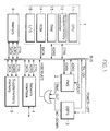
- the network hibernation system comprises controller 1, power controlling part 2 which is connected to bus power supply 3 for backing up of data which is connected to bus, network interface 4, supplimentary memory 5, and nonvolatile memory 6.
- the controller 1 comprises CPU (central process unit) 11, supplimentary controller 12, RAM 13, ROM 14, I/O (input/output) 15, the supplimentary controller meaning bus controller, DMA controller, interrupt controller, etc.
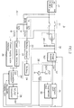
- the power supply 3 for backing up of data in the network hibernation system comprises an AC (alternating current) power supply 31; a linear converting rectifier 32 which is composed of a transformer (TF) is connected to the two output terminals of the AC rectifier 31 and diodes (D31, D32) and condensors (C31, C32) connected to the output terminals of the TF; a battery 34 and a battery charger 33 which are cascaded into the linear converting rectifier 32; a power supply state detector 36 which is connected to the output terminal of the linear converting rectifier 32; a power supply switching state detector 36; a DC (direct current) converting controller 37 to which the output signals of the power supply detector 35 and the power supply switching state detector 37 are inputted and the power supply interruption detecting signal to system part 3C and the power supply signal are applied; a DC/DC converter 38 which is connected to the output terminals of the battery charger 33 and the DC converting controller 37 and of which output terminal is connected to the output
- the technic of the power supply 3 for backing up data is as shown in the above mentioned patent application No. 93-31255, entitled ""The supplimentary power supply for backing up the working environment in an emergency.”
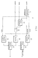
- the power controller means 2 in the network hibernation system comprises an address decoder 21 which is connected to the address bus; a mask register 22, the first and the second registers 23, 26 which are connected to the data bus and the address decoder 21, respectively; an AND gate of which input terminal is connected to the first mask register 22 and event signal line; a counter of which input terminal is connected to the output terminal of the AND gate; a first comparator 25 which is connected to the output terminals of the first time register 23 and counter 24; and a second comparator which is connected to the output terminals of the second time register 26 and counter 24.
- the power controller means 2 composed of the elements as shown in FIG. 3 is described, but the technical range of the invention is not restricted to this and also the power controller means 2 can be realized by the technic shown in the Korean patent application No 92-14590, entitled "The circuit producing the power interruption signal in the computer peripheral equipment.”
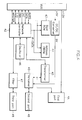
- the network interface 4 in the network hibernation system comprises a DC/AC converter 41 which is connected to bus; a network controller 42; a boot ROM 43 and an address PROM 44 which are connected to the bus and the network controller 42; an oscillator 46 and a transformer 45 which are connected to the network controller 42; a first port 4A which is connected to the bus and the transformer 45; a tranceiver 4B which is connected to the DC/DC converter 41 and transformer 45; a second port 49 which is connected to the tranceiver 4B; a filter 47 which is connected to the network controller 42; and a third port 48 which is connected to the filter 47.
- the loading process of the network hibernation module comprises a step S50 in which the operation starts; a step S51 in which the network interface is initialized; a step S52 in which it is estimated whether the network hibernation is enabled; a step S53 in which the event signal used in the network interface is disabled in the mask register in case that the network hibernation is enabled; a step S54 in which the information of the network interface is stored in the network hibernation information area in memory; a step S55 in which the fact that the network hibernation module is loaded in the system and the interrupt information or the address of the network hibernation module are stored in the memory; a step S56 in which the process routine of the network driver is loaded in the memory; a step S57 in which it is estimated whether the network hibernation is enabled again; a step S58 in which the network hibernation module is loaded in the memory in case that the network hibernation is enabled; and a step S59 in which the operation
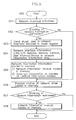
- the suspend process of the hibernation module comprises steps S61-S64 in which when the electric power is off during the operation of the computer, the power supply for backing up of data outputs the AC power supply interruption detecting signal with the power of the battery applied; a step S65 in which the power controller outputs time-out signal in case that the event is not produced for some time during the operation of the computer; a step S66 in which the hibernate interruption is produced in CPU in case that the AC power supply interruption signal or the time-out signal is produced; a step S67 in which it is estimated whether the hibernation support network driver is installed; a step S68 in which the network hibernation module is invoked in case that the hibernation support network driver is installed; a step S69 in which all the state of the hardware in the computer is stored in the present memory; a step S6A in which the content of every memory in the present computer is stored in the supplimentary memory; a step S6B in which the power
- the suspend process of the network hibernation module comprises a step S71 of invoking; a step S72 in which it is estimated whether the network hibernation is enabled; a step S73 in which the network interface is reset in case that the network hibernation is enabled; a step S74 in which the network interface is disabled; a step S75 in which the content of the local memory is stored in case that there is the local memory in the network interface; and a step S76 of returning to the hibernation module.
- the resuming process of the hibernation module comprises a step S92 in which the initializing and self-examining of the computer is performed in the state S91 of power-off when the power is applied again; a step S93 in which it is estimated whether it is in the hibernation mode; a step S94 in which the normal booting process is performed in case of non-hibernation mode; a step S95 in which the content of all the memory is recovered from the supplimentary memory in case of the hibernation mode; a step S96 in which the working environment is recovered to the previous state before the power supply is off; a state S97 in which it is estimated whether it is in the network hibernation state is; a state S98 in which the network hibernation module is invoked in case of the network hibernation state; and a step S99 in which the computer operates in the state previous to the hibernation.
- the resuming process of the hibernation module comprises a step S11 of invoking; a step S12 in which it is estimated whether the network hibernation is enabled; a step S13 in which the network interface is initialized in case that the network hibernation is enabled; a step S14 in which the content of the local memory is recovered in case there is the local memory in the network interface; a step S16 in which the network interface is enabled; and a step S17 of returning to the hibernation module.
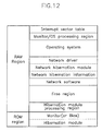
- the memory map of the RAM in the network hibernation system comprises an interrupt vector area; a processing area of a monitor/operating system (OS); an operating system area; a network driver area; a network hibernation module area; a network hibernation information area; a network software area; a free space area; and a hibernation module processing area.
- OS monitor/operating system
- the memory map of the RAM in the network hibernation system comprises an interrupt vector area; a processing area of a monitor/operating system (OS); an operating system area; a network driver area; a network hibernation module area; a network hibernation information area; a network software area; a free space area; and a hibernation module processing area.
- the memory map in the network hibernation system comprises a hibernation setting up area; a hibernation state area; a hibernation parameter area; a network hibernation area; and a network hibernation interrupt or a network hibernation address area.
- the computer starts with its power on and the network hibernation system according to an embodiment of the invention operates by loading the network hibernation module with network driver module into the system memory.
- the loading of the network hibernation module into the memory is shown in FIG.5 and is explained as follows :
- the CPU 11 in the controller 1 initializes the network interface and self-examines. In the second place, it is estimated whether the network hibernation is enabled by estimating the hibernation install flag in the nonvolatile memory 6.
- CPU 11 in the controller 1 disables the corresponding flag in the mask register 22 shown in FIG.3 to disable the event signal used in the network interface.
- Data is received continuously through the network interface 4 even when the network is not used once the network is connected to the computer.
- the power controlling means 2 misinterprets the computer to be operated although the computer is not used.
- the power can be interrupted automatically when the computer is not used for sometime only after the network interface 4 disables the corresponding interruption (that is to say, the corresponding event signal) by using the mask register 22 shown in FIG.3.
- CPU 11 in controller 1 stores the corresponding information such as the interrupt signal used in the network interface, I/O address, direct memory access, memory information, etc. on the network hibernation area in the RAM area as shown in FIG. 12.
- CPU 11 in controller 1 stores information relating to the network hibernation on the nonvolatile memory.
- the network hibernation interrupt vector should be added to or be changed in the interrupt vector table shown in FIG. 12 when the network hibernation is used.
- the CPU 11 in the controller 1 terminates after the network driver module and the network hibernation module are installed in the system memory.
- the suspend processes S67 and S68 of the hibernation module shown in Fig. 6 are called out and are performed by installing the network hibernation module on the memory if the interruption of electric power occurrs due to the abrupt interruption of the electric power or being not used for sometime while the controller 1 operates as a computer after the network hibernation system starts its operation.
- the power supply 3 for backing up of data produces AC power interruption detecting signal after the power supply is supplied to the system by a battery.
- the power supply 3 for backing up of data starts its operation.
- the circuit operation can be classified into four cases: a case (A) that the power supply is applied to and the power switch is turned on; a case (B) that the power supply is applied and the power switch is turned off; a case (C) that the power supply is not applied to by halting of the AC power supply 31 due to interruption of electric power or any carelessness; and a case (D) that the power supply is not applied and the power switch is turned on.
- AC power which is supplied from the AC power supply 31 is supplied to the main power supply 3A through the power switch 39 and the power supply 3A2 generates DC power of 5V and 12V after the AC power is rectified by the bridge rectifier 3A1 in the main power supply 3A.
- the DC power generated makes the computer operate by being supplied to the expanded slot 3D to which the expanded card such as the system 3C, a video card, a music card, a fax/modem card, etc. is provided. Also, the AC power which is supplied from the AC power supply 31 is rectified to DC power by the diodes D31, D32 and the condensers C31, C32 after the voltage is decreased by the transformer TF in the linear converting rectifier.
- the DC power of the linear converting rectifier 32 is supplied to the battery charger 33 so that the battery may be charged and a low level signal is outputted to the expanded slot interruptor 3B from the DC/DC converter by stopping the operation of DC/DC converter 38 by the DC converting controller 37 if the power supply state detector 35 estimates the state of the AC power as being normal.
- the transistor Q in the expanded slot interruptor 3B is turned off and the FET is turned on and thus DC power of 5V is supplied from the power supply 3A2 to the expanded slot 3D.
- the main power supply 3A does not operate if the power of the AC power supply 31 is cut off. Also, the power of the AC power supply 31 is rectified to a DC power by the linear converting rectifier 32 and the rectified DC power is supplied to the battery charger 34 and thus the battery is charged. If the power supply state detector 35 estimates the state of the AC power as being normal, the power does not discharge from the battery 34 by halting the operation of DC/DC converter 38.
- the main power supply 3A and the linear converting rectifier 32 stop their operation by the interruption of the AC power supply and thus the power applied to the system 3C and the extended slot 3D may be attenuated gradually. Also, because the linear converting rectifier 32 does not produce DC power, the battery charger 33 stops its operation.
- the power supply state detector 4 estimates the AC power as being normal and the power switch state detecter 5 estimates as the power switch 39 is turned on and thus the DC converting controller 37 produces a control signal to operate DC/DC converter 38.
- the DC converting controller 37 outputs an AC power interruption detecting signal to the system 3C.
- the said system 3C means all composition except the power supply 3 for backing up of data in Fig. 1. If a control signal of the DC converting controller 37 is inputted to the DC/DC converter 38, the DC power 4 charged in the battery 3 is converted to DC power through the DC/DC power converter 38 and thereafter, is supplied to the output terminal of the bridge rectifier 3A1 of the main power supply 3A through the two diodes.
- the power supply 3A2 in the main power supply 3A is operated by the DC power supplied from DC/DC converter 38 and thus the attenuated output power of the power supply 3A2 ascends again.
- the working environment can be backed up by the AC power interruption detecting signal inputted from DC converting controller 37 and the DC power of 5V and 12V supplied from the power supply 3A2 in the system 3C.
- the transistor Q is turned on and the FET is turned off in the extended slot interruptor 3B by the AC power interruption detecting signal in order that the 5V DC power of the power supply 3A2 may not be supplied to the extended slot 3D.
- the power controller 2 produces the time-out signal in case the event signal is not inputted for sometime.
- the address decoder 21 decodes address to designate each register 22, 23, 26 from an address signal (ADRS) inputted from the address bus.
- ADRS address signal
- the mask register 22 and the first and second time register 23, 26 are selected by the address signal inputted from the address decoder 21, and at the time of setting up, the initial value is set up which is always outputted.
- mask register 22 the information which can mask the event signal is set up and in the first and second time registers, a reference time value is set up.
- the counter 24 is reset as"0" when the logic product of the event signal and the content of the mask register 22 is "1" in the AND gate 28, that is, the interrupt signal is inputted from the peripheral equipment.
- the counter 24 keeps on counting. If the value of the counter 24 is the same as the value of the first time register 23, that is, the interrupt signal that is not masked in the mask register 22 is not inputted from the peripheral equipment during the reference time, the first comparator 25 outputs the time-out signal.
- the AC power interruption detecting signal outputted from the power supply 3 for backing up of data and the time-out signal outputted from the power supply controller 2 are inputted to the CPU 11 in the controller 1 through the OR gate and the system bus as the hibernation interrupt signal.
- the CPU 1 in the controller 1 estimates that the hibernation supporting network driver is installed and, in case that the hibernation supporting network driver is installed, invokes the suspend process of the network hibernation module as shown in FIG. 8.
- the suspend processes (S71 - S76) of the network hibernation module are performed as shown in FIG. 7.
- the CPU 11 in the controller 1 estimates that the network hibernation is enabled by estimating that the hibernation install flag of the nonvolatile memory 6 is enabled.
- the CPU 11 in the controller 1 resets the network interface 4 and thereafter, disables the network interface 4.
- the computer After the suspend process of the network hibernation module is performed, the computer returns to the hibernation module.
- the CPU 11 in the controller 1 stores the present hardware state of the computer in the RAM 13 and then, all the contents of the memory in the present computer are stored in the supplimentary memory 5.
- the CPU 11 in the controller 11 outputs the power interrupt signal to the power supply 3 for backing up of data. If the power interrupt signal is inputted, the power supply 3 for backing up of data interrupts the power of the battery 34 and power supply 3A2 and makes the computer go into the hibernation state.
- the DC converting controller 37 stops the operation of the DC/DC converter. And thus, because the power of the battery 34 is cut off, the 5 V and 12V dc power may not be supplied. Also, if the power interrupt signal is inputted to the power supply 3A2, the application of the power is interrupted by the interruption of the power supply 3A2. On the other hand, if the power is applied again or data is inputted by a user in the hibernation state in which the power of the computer is turned off, the resume processes S93 -S99 of the hibernation module shown in FIG. 9 are called as follows :
- the CPU 11 in the controller 1 initializes the computer and self-examines and thereafter, estimates whether it is in the hibernation mode.
- the CPU 11 in the controller 1 boots the computer normally. But if the state is in the hibernation mode, the CPU 11 in the controller 1 recovers the working environment of the computer to the former state by storing all the contents of the memory in the RAM.
- the CPU 11 in the controller 1 estimates whether the state is in the network hibernation state by estimating whether the hibernation flag of the nonvolatile memory is enabled and invokes the resume process of the network hibernation module shown in FIG. 11 in case it is in the network hibernation state.
- the resume processes S11-S17 of the network hibernation module are performed as follows :
- the CPU 11 in the controller 1 estimates whether the network hibernation is enabled. If the network hibernation is enabled, the CPU 11 in the controller 1 initializes the network interface 4. If there is the local memory in the network interface 4 in this step, its content is recovered.
- the CPU 11 in the controller 1 resets the network interface 4 and thereafter, enables the network interface 4.
- the CPU 11 in the controller 1 continues to operate the computer as in the former state of the hibernation.
- the working environment can be recovered to the former state and also, if the computer does not operate for sometime in the network environment, the power supply is interrupted automatically, and thereafter, if the power supply is applied again, the computer recovers the former state so that the power consumed can be retrenched.
- the effect of this invention can be utilized in the area of the computer which has automatic backing up function in an emergency and a retrenching function of the electric power.
Abstract
supply (3) for backing up of data which outputs a power interruption detection signal when the power supply is cut off with the power supplied urgently by the battery (34) and cuts off the power of battery when the power interruption signal is inputted; a controller (1) which backs up data in network environment and
thereafter,outputs the power interruption signal when the power interruption detection signal or the time-out signal is inputted and recovers the data and environment backed up
on the memory so that the computer may operate in the same state as the former state; a network interface (4)for the network connection; a supplementary memory (5)in which the data for backing up the hardware state or the working environment are stored in the computer; and a memory (6) in which the hibernation information is stored, and recovers the working environment to the former state when the power is cut off abruptly in the network environment and thereafter, the power is turned on again and also, interrupts the power automatically when the computer is not used for sometime and thereafter, recovers the working environment to the former state when the power is applied again so that the consumed power may be saved, a process comprising the steps of estimating whether the network hibernation is enabled and consequently loading the network hibernation module.
Description
- This invention relates to a network hibernation system, particularily to a network hibernation system in which a working environment can be recovered to a former state when a power supply is applied again after the power supply was cut off abruptly in a computer in network environment and also,the power supply is cut off automatically when the computer is not used for sometime and the working environment is recovered to the former state when a user applies a power supply to the computer again.
- In this invention, the hibernation system means a system including two functions as follows: firstly, an emergent automatic recovering function in which working conditions are stored in a supplimentary memory device such as a hard disk when the power supply is cut off abruptly by the interruption of electric power or any mistake of a user and thereafter, the state before the cutting off of the power supply is recovered by using the stored content in the supplementary memory device when the power supply is applied to the computer again; secondly, a power saving function in which when the computer is not used for a given time while using the computer, the power supply is cut off automatically after the working condition is stored in a supplimentary memory device such as a hard disk and thereafter, the working environment is recovered to the state before the cutting off of the power supply by the content of the supplimentary memory when the power supply is applied to the computer again.
- And also, in this invention, the network hibernation system means the system which supports the hibernation system when the computer is used in the network environment.
- The phrase 'in the network environment' means the state in which a user uses the computer in connection with a network.
- Recently, in personal computers, the hibernation system having the emergent automatic recovering function and the power saving function has been gradually popularized and its market has also been expanded.
- The similar prior arts relating to the emergent automatic recovering function and power saving function according to the invention are as shown in an an invention filed under Korea Patent Application No.93-31255 entitled "The supplimentary power supply for backing up the working environment in an emergency," filed on December 30, 1993, Korea Patent Application No.94-13919 entitled "The stop clock controlling machine," filed on June 20, 1994. Korea Utility Model Application No. 93-3116 entitled "The power controlling device of the computer peripheral equipment," filed on March 4, 1993. Korea Patent Application No.92-14590 entitled "The circuit generating the power interruption signal in the computer peripheral equipment," filed on August 13, 1992.
- But the technology specified in the prior arts suffers drawbacks that in network environment, particularily in PC (personal computer) LAN (Local Area Network) environment, when the power supply is cut off by the abrupt interruption of electric power or any fault of a user when using the computer, the data can be recovered only in a state independent of a network environment, otherwise, the data is lost.
- It is an object of this invention to provide a system in which when the power supply is cut off by the abrupt interruption of electric power or any fault of a user while using the computer, the working environment is recovered to the former state after the power supply is turned on again, and in network environment, when the computer is not used for a given time, the power supply is cut off automatically and the working environment is recovered to the former state when the power supply is turned on again, so that the electric power consumed may be minimized.
- To achieve the object of this invention, a hibernation system according to an embodiment of this invention comprises a power controller for outputing time-out signal when an event does not occure for a given time in the peripheral equipment; a power supply for backing up of data which outputs the power interruption detection signal when the power supply is cut off by the abrupt interruption of electric power or any fault of a user with the power supplied urgently by a battery and also, cuts off the power supply when a power interruption signal is applied; a controller which places the computer in the hibernation state by outputting the power interruption signal after data is backed up in the network environment when the power interruption detection signal is inputted from the power controller or the time-out signal is inputted from the power supply and also, operates the computer in the former network environment by recovering the backed-up data and the working environment when the power is applied again; a network interface for network connection; a supplimentary memory in which the hardware state of the computer and the data for backing up of the working environment are stored; and a memory in which some hibernation information are stored.
- As to the means to accomplish the object of the invention, the loading method of the network hibernation module of the invention comprises an initializing step in which the network interface is initialized when the operation is begun; a disabling step in which the event signal is disabled in a mask register when the network hibernation is enabled after it is estimated whether the network hibernation is enabled; a storing step in which the network interface information is stored in the network hibernation information area in the memory; a storing step in which the information representing the fact that the network hibernation module is loaded in the system and the interrupt information in the network hibernation module or address are stored in the memory; a loading step in which a process routine of the network driver is loaded in the memory; and a step in which the network hibernation module is loaded in the memory when the network hibernation is enabled after it is estimated whether the network hibernation is enabled and thereafter, the operation is terminated.
- To accomplish the object, a suspend method of the invention comprises: a step in which the power supply for backing up of data outputs an AC(alternating current) interruption detection signal with the power of battery applied; a step in which the power controller outputs the time-out signal when the event has not been occurred for sometime during the operation of the computer; a step in which the hibernation interrupt occurs in CPU and thereafter, it is estimated whether the hibernation supporting network driver is installed when the AC interruption detection signal and the time-out signal occur; a step invoking network hibernation module in case the hibernation support network driver is installed; a step resetting the network interface in case it is estimated whether the network hibernation is enabled and then determined to be enabled; a step disabling the network interface and returning to the hibernation module after the content of local memory is stored in case there is the local memory in the network interface; a step storing all the content in memory to the supplimentary memory after the entire state of hardware in the present computer are stored; a step interrupting the power with the power supply for backing up of data by outputting the power-off signal to the power supply for backing up of data; and a step turning the computer to the hibernation state.
- As a means to accomplish the object of the invention, the resuming method of this invention comprises a step initializing and self-examining the computer when the power is applied again in the state of power-off; a step recovering the working environment to the state previous to the power-off by normally booting in case it is not the hibernation mode and by recovering all the content of memory from the supplimentary memory in case it is the hibernation mode after it is estimated whether the hibernation mode; a step invoking the network hibernation module in case of the network hibernation state after it is estimated whether it is the network hibernation state; a step initializing the network interface in case the network hibernation is enabled after it is estimated whether the network hibernation is enabled if the network hibernation module is invoked; a step recovering the content of local memory in case that there is local memory in the network interface and resetting the network interface; a step returning to the hibernation module after the network interface is enabled; and a step operating the computer in the previous state to the hibernation.
- An embodiment of the present invention will now be described, by way of example only, with reference to the accompanying drawings, wherein:-
- FIG. 1 is a block diagram showing the network hibernation system according to a preferred embodiment of the invention;
- FIG. 2 is a block diagram showing the power supply for backing up of data in the hibernation system according to a preferred embodiment of the invention;
- FIG. 3 is a block diagram showing the power controller in the network hibernation system according to a preferred embodiment of the invention;
- FIG. 4 is a block diagram showing the network interface in the network hibernation system according to a preferred embodiment of the invention;
- FIG. 5 is a flowchart of the loading process to the network hibernation module according to a presently preferred embodiment of the invention;
- FIG. 6 is a flowchart of the suspend process to the hibernation module according to a preferred embodiment of the invention;
- FIG. 7 is a flowchart the suspend process to the network hibernation module according to a presently preferred embodiment of the invention;
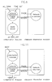
- FIG. 8 is a drawing showing the state in which the network hibernation module is invoked in case of power-off according to a preferred embodiment of the invention;
- FIG. 9 is a flowchart to the resume process of the hibernation module according to a preferred embodiment of the invention;
- FIG. 10 is a flowchart to the resume process of the network hibernation module according to a preferred embodiment of the invention;
- FIG. 11 is a drawing showing the state in which the network hibernation module is invoked in case of booting according to a preferred embodiment of the invention;
- FIG. 12 is a drawing showing the memory map of RAM and ROM in the network hibernation system according to a preferred embodiment of the invention; and
- FIG. 13 is a drawing showing the memory map of the RAM and ROM in the network hibernation system according to a preferred embodiment of the invention.
- As shown in Fig. 1, the network hibernation system according to an embodiment of the invention comprises
controller 1,power controlling part 2 which is connected tobus power supply 3 for backing up of data which is connected to bus,network interface 4,supplimentary memory 5, andnonvolatile memory 6. - The
controller 1 comprises CPU (central process unit) 11, supplimentary controller 12,RAM 13,ROM 14, I/O (input/output) 15, the supplimentary controller meaning bus controller, DMA controller, interrupt controller, etc. - As shown in FIG.2, the
power supply 3 for backing up of data in the network hibernation system according to an embodiment of the invention comprises an AC (alternating current)power supply 31; alinear converting rectifier 32 which is composed of a transformer (TF) is connected to the two output terminals of theAC rectifier 31 and diodes (D31, D32) and condensors (C31, C32) connected to the output terminals of the TF; abattery 34 and abattery charger 33 which are cascaded into thelinear converting rectifier 32; a powersupply state detector 36 which is connected to the output terminal of thelinear converting rectifier 32; a power supplyswitching state detector 36; a DC (direct current)converting controller 37 to which the output signals of thepower supply detector 35 and the power supplyswitching state detector 37 are inputted and the power supply interruption detecting signal tosystem part 3C and the power supply signal are applied; a DC/DC converter 38 which is connected to the output terminals of thebattery charger 33 and theDC converting controller 37 and of which output terminal is connected to the output terminal of the bridge rectifier 3A1 in themain power supply 3A through two diodes; amain power supply 3A of which the output terminal of theAC power supply 31 is connected to thebridge rectifier 3 A1 through power switch 39 and the output terminal of the bridge rectifier 3A1 is connected to power supply 3A2; and an augmentedslot interrupter 3B of which the output terminal of theDC converting controller 37 to output the back up starting signal of the working environment of theDC controller 37 is connected to a base of a transistor Q through resistor R32 and a gate of a field effect transistor FET and the 12 volt output terminal of the power supply 3A2 are connected to the colletor of the transistor TR and the 5 volt output terminal of the power supply 3A2 is connected to the drain of the FET and the source of the FET is connected to the augmentedslot 3D. - The technic of the
power supply 3 for backing up data is as shown in the above mentioned patent application No. 93-31255, entitled ""The supplimentary power supply for backing up the working environment in an emergency." - As shown in Fig. 3, the power controller means 2 in the network hibernation system according to an embodiment of the invention comprises an
address decoder 21 which is connected to the address bus; amask register 22, the first and thesecond registers address decoder 21, respectively; an AND gate of which input terminal is connected to thefirst mask register 22 and event signal line; a counter of which input terminal is connected to the output terminal of the AND gate; afirst comparator 25 which is connected to the output terminals of the first time register 23 andcounter 24; and a second comparator which is connected to the output terminals of the second time register 26 andcounter 24. - In the embodiment of the invention, the power controller means 2 composed of the elements as shown in FIG. 3 is described, but the technical range of the invention is not restricted to this and also the power controller means 2 can be realized by the technic shown in the Korean patent application No 92-14590, entitled "The circuit producing the power interruption signal in the computer peripheral equipment."
- As shown in FIG.4, the
network interface 4 in the network hibernation system according to an embodiment of the invention comprises a DC/AC converter 41 which is connected to bus; anetwork controller 42; aboot ROM 43 and anaddress PROM 44 which are connected to the bus and thenetwork controller 42; anoscillator 46 and atransformer 45 which are connected to thenetwork controller 42; afirst port 4A which is connected to the bus and thetransformer 45; atranceiver 4B which is connected to the DC/DC converter 41 andtransformer 45; asecond port 49 which is connected to thetranceiver 4B; afilter 47 which is connected to thenetwork controller 42; and athird port 48 which is connected to thefilter 47. - As shown in FIG.5, the loading process of the network hibernation module according to an embodiment of the invention comprises a step S50 in which the operation starts; a step S51 in which the network interface is initialized; a step S52 in which it is estimated whether the network hibernation is enabled; a step S53 in which the event signal used in the network interface is disabled in the mask register in case that the network hibernation is enabled; a step S54 in which the information of the network interface is stored in the network hibernation information area in memory; a step S55 in which the fact that the network hibernation module is loaded in the system and the interrupt information or the address of the network hibernation module are stored in the memory; a step S56 in which the process routine of the network driver is loaded in the memory; a step S57 in which it is estimated whether the network hibernation is enabled again; a step S58 in which the network hibernation module is loaded in the memory in case that the network hibernation is enabled; and a step S59 in which the operation is terminated.
- As shown in Fig.6, the suspend process of the hibernation module according to an embodiment of the invention comprises steps S61-S64 in which when the electric power is off during the operation of the computer, the power supply for backing up of data outputs the AC power supply interruption detecting signal with the power of the battery applied; a step S65 in which the power controller outputs time-out signal in case that the event is not produced for some time during the operation of the computer; a step S66 in which the hibernate interruption is produced in CPU in case that the AC power supply interruption signal or the time-out signal is produced; a step S67 in which it is estimated whether the hibernation support network driver is installed; a step S68 in which the network hibernation module is invoked in case that the hibernation support network driver is installed; a step S69 in which all the state of the hardware in the computer is stored in the present memory; a step S6A in which the content of every memory in the present computer is stored in the supplimentary memory; a step S6B in which the power interruption signal is outputted to the power supply for backing up of data; a step S6C in which the power supply for backing up of data cuts off the power; and a step S6D in which the computer reaches the hibernation state.
- As shown in Fig.7, the suspend process of the network hibernation module according to an embodiment of the invention comprises a step S71 of invoking; a step S72 in which it is estimated whether the network hibernation is enabled; a step S73 in which the network interface is reset in case that the network hibernation is enabled; a step S74 in which the network interface is disabled; a step S75 in which the content of the local memory is stored in case that there is the local memory in the network interface; and a step S76 of returning to the hibernation module.
- As shown in Fig. 9, the resuming process of the hibernation module according to an embodiment of the invention comprises a step S92 in which the initializing and self-examining of the computer is performed in the state S91 of power-off when the power is applied again; a step S93 in which it is estimated whether it is in the hibernation mode; a step S94 in which the normal booting process is performed in case of non-hibernation mode; a step S95 in which the content of all the memory is recovered from the supplimentary memory in case of the hibernation mode; a step S96 in which the working environment is recovered to the previous state before the power supply is off; a state S97 in which it is estimated whether it is in the network hibernation state is; a state S98 in which the network hibernation module is invoked in case of the network hibernation state; and a step S99 in which the computer operates in the state previous to the hibernation.
- As shown in Fig. 10, the resuming process of the hibernation module according to an embodiment of the invention comprises a step S11 of invoking; a step S12 in which it is estimated whether the network hibernation is enabled; a step S13 in which the network interface is initialized in case that the network hibernation is enabled; a step S14 in which the content of the local memory is recovered in case there is the local memory in the network interface; a step S16 in which the network interface is enabled; and a step S17 of returning to the hibernation module.
- As shown in Fig. 12, the memory map of the RAM in the network hibernation system according to the embodiment of the invention comprises an interrupt vector area; a processing area of a monitor/operating system (OS); an operating system area; a network driver area; a network hibernation module area; a network hibernation information area; a network software area; a free space area; and a hibernation module processing area.
- As shown in Fig. 13, the memory map in the network hibernation system according to an embodiment of the invention comprises a hibernation setting up area; a hibernation state area; a hibernation parameter area; a network hibernation area; and a network hibernation interrupt or a network hibernation address area.
- The computer starts with its power on and the network hibernation system according to an embodiment of the invention operates by loading the network hibernation module with network driver module into the system memory.
- The loading of the network hibernation module into the memory is shown in FIG.5 and is explained as follows :
- At first, the
CPU 11 in thecontroller 1 initializes the network interface and self-examines. In the second place, it is estimated whether the network hibernation is enabled by estimating the hibernation install flag in thenonvolatile memory 6. - In case the network hibernation is enabled,
CPU 11 in thecontroller 1 disables the corresponding flag in themask register 22 shown in FIG.3 to disable the event signal used in the network interface. - The reason for disabling the event signal is as follows:
- Data is received continuously through the
network interface 4 even when the network is not used once the network is connected to the computer. - By the way, since the
network interface 4 produces interruption unconditionally at the time that data is received, the power controlling means 2 misinterprets the computer to be operated although the computer is not used. - Accordingly the power can be interrupted automatically when the computer is not used for sometime only after the
network interface 4 disables the corresponding interruption (that is to say, the corresponding event signal) by using themask register 22 shown in FIG.3. After the event signal is disabled,CPU 11 incontroller 1 stores the corresponding information such as the interrupt signal used in the network interface, I/O address, direct memory access, memory information, etc. on the network hibernation area in the RAM area as shown in FIG. 12. Next,CPU 11 incontroller 1 stores information relating to the network hibernation on the nonvolatile memory. At this time, the network hibernation interrupt vector should be added to or be changed in the interrupt vector table shown in FIG. 12 when the network hibernation is used. - The
CPU 11 in thecontroller 1 terminates after the network driver module and the network hibernation module are installed in the system memory. - As described above, the suspend processes S67 and S68 of the hibernation module shown in Fig. 6 are called out and are performed by installing the network hibernation module on the memory if the interruption of electric power occurrs due to the abrupt interruption of the electric power or being not used for sometime while the
controller 1 operates as a computer after the network hibernation system starts its operation. - If the power supply is interrupted during the operation due to the abrupt interruption of electric power, the
power supply 3 for backing up of data produces AC power interruption detecting signal after the power supply is supplied to the system by a battery. - In case of the interruption of electric power, the overall operation of the
power supply 3 for backing up of data which produces the AC power interruption detecting signal while the power supply is applied to the system by the battery is as follows : - If the power is applied to the power switch39 and
linear converting rectifier 32 from theAC power supply 31, thepower supply 3 for backing up of data starts its operation. - The circuit operation can be classified into four cases: a case (A) that the power supply is applied to and the power switch is turned on; a case (B) that the power supply is applied and the power switch is turned off; a case (C) that the power supply is not applied to by halting of the
AC power supply 31 due to interruption of electric power or any carelessness; and a case (D) that the power supply is not applied and the power switch is turned on. - In this case, AC power which is supplied from the
AC power supply 31 is supplied to themain power supply 3A through the power switch 39 and the power supply 3A2 generates DC power of 5V and 12V after the AC power is rectified by the bridge rectifier 3A1 in themain power supply 3A. - The DC power generated makes the computer operate by being supplied to the expanded
slot 3D to which the expanded card such as thesystem 3C, a video card, a music card, a fax/modem card, etc. is provided. Also, the AC power which is supplied from theAC power supply 31 is rectified to DC power by the diodes D31, D32 and the condensers C31, C32 after the voltage is decreased by the transformer TF in the linear converting rectifier. - The DC power of the
linear converting rectifier 32 is supplied to thebattery charger 33 so that the battery may be charged and a low level signal is outputted to the expandedslot interruptor 3B from the DC/DC converter by stopping the operation of DC/DC converter 38 by theDC converting controller 37 if the powersupply state detector 35 estimates the state of the AC power as being normal. - If the low level signal is inputted from the DC/
DC converter 38, the transistor Q in the expandedslot interruptor 3B is turned off and the FET is turned on and thus DC power of 5V is supplied from the power supply 3A2 to the expandedslot 3D. - Because a user turns off the power switch 39, the
main power supply 3A does not operate if the power of theAC power supply 31 is cut off. Also, the power of theAC power supply 31 is rectified to a DC power by the linear convertingrectifier 32 and the rectified DC power is supplied to thebattery charger 34 and thus the battery is charged. If the powersupply state detector 35 estimates the state of the AC power as being normal, the power does not discharge from thebattery 34 by halting the operation of DC/DC converter 38. - In this case as the case that the
AC power supply 31 is turned off by the abrupt interruption of electric power or any mistake of a user during the operation of the computer, themain power supply 3A and the linear convertingrectifier 32 stop their operation by the interruption of the AC power supply and thus the power applied to thesystem 3C and theextended slot 3D may be attenuated gradually. Also, because the linear convertingrectifier 32 does not produce DC power, thebattery charger 33 stops its operation. - At this time the power
supply state detector 4 estimates the AC power as being normal and the powerswitch state detecter 5 estimates as the power switch 39 is turned on and thus theDC converting controller 37 produces a control signal to operate DC/DC converter 38. - At the same time the
DC converting controller 37 outputs an AC power interruption detecting signal to thesystem 3C. The saidsystem 3C means all composition except thepower supply 3 for backing up of data in Fig. 1. If a control signal of theDC converting controller 37 is inputted to the DC/DC converter 38, theDC power 4 charged in thebattery 3 is converted to DC power through the DC/DC power converter 38 and thereafter, is supplied to the output terminal of the bridge rectifier 3A1 of themain power supply 3A through the two diodes. - As shown in the above, the power supply 3A2 in the
main power supply 3A is operated by the DC power supplied from DC/DC converter 38 and thus the attenuated output power of the power supply 3A2 ascends again. - Accordingly, the working environment can be backed up by the AC power interruption detecting signal inputted from
DC converting controller 37 and the DC power of 5V and 12V supplied from the power supply 3A2 in thesystem 3C. - On the other hand,because the power charged in the
battery 34 is not sufficient to operate the total system including the extendedslot 3D, the transistor Q is turned on and the FET is turned off in the extendedslot interruptor 3B by the AC power interruption detecting signal in order that the 5V DC power of the power supply 3A2 may not be supplied to theextended slot 3D. - In this case, because the
AC power supply 31 is not connected and also the power switch 39 is turned off, themain power supply 3A and the linear convertingrectifier 32 do not operate. - On the other hand, the
power controller 2 produces the time-out signal in case the event signal is not inputted for sometime. - The constitution of the
power controller 2 is explained with reference to Fig. 3 as follows : - The
address decoder 21 decodes address to designate eachregister - The
mask register 22 and the first andsecond time register address decoder 21, and at the time of setting up, the initial value is set up which is always outputted. - In
mask register 22, the information which can mask the event signal is set up and in the first and second time registers, a reference time value is set up. - The
counter 24 is reset as"0" when the logic product of the event signal and the content of themask register 22 is "1" in the ANDgate 28, that is, the interrupt signal is inputted from the peripheral equipment. - If the logic product of the event signal and the content of the
mask register 22 is "0" in the ANDgate 28, that is, the interrupt signal is not inputted from the peripheral equipment or the interrupt signal masked in themask register 22 is inputted, thecounter 24 keeps on counting. If the value of thecounter 24 is the same as the value of thefirst time register 23, that is, the interrupt signal that is not masked in themask register 22 is not inputted from the peripheral equipment during the reference time, thefirst comparator 25 outputs the time-out signal. - As shown in the above, the AC power interruption detecting signal outputted from the
power supply 3 for backing up of data and the time-out signal outputted from thepower supply controller 2 are inputted to theCPU 11 in thecontroller 1 through the OR gate and the system bus as the hibernation interrupt signal. - If the hibernation interrupt signal is inputted, the
CPU 1 in thecontroller 1 estimates that the hibernation supporting network driver is installed and, in case that the hibernation supporting network driver is installed, invokes the suspend process of the network hibernation module as shown in FIG. 8. - If the suspend process of the network hibernation module is invoked, the suspend processes (S71 - S76) of the network hibernation module are performed as shown in FIG. 7.
- At first, the
CPU 11 in thecontroller 1 estimates that the network hibernation is enabled by estimating that the hibernation install flag of thenonvolatile memory 6 is enabled. - In case the network hibernation is enabled, the
CPU 11 in thecontroller 1 resets thenetwork interface 4 and thereafter, disables thenetwork interface 4. - In this step, if the local memory remains in the network interface, its content is stored.
- After the suspend process of the network hibernation module is performed, the computer returns to the hibernation module. In case the hibernation supporting network driver is not installed in this step or the computer returns from the suspend process of the network hibernation module as shown above, the
CPU 11 in thecontroller 1 stores the present hardware state of the computer in theRAM 13 and then, all the contents of the memory in the present computer are stored in thesupplimentary memory 5. Next, theCPU 11 in thecontroller 11 outputs the power interrupt signal to thepower supply 3 for backing up of data. If the power interrupt signal is inputted, thepower supply 3 for backing up of data interrupts the power of thebattery 34 and power supply 3A2 and makes the computer go into the hibernation state. - As shown in the above, the operation of the
power supply 3 for backing up of data which interrupts the battery power in case the power interrupt signal is inputted can be explained with reference to FIG.2 as follows : - If the power interrupt signal is inputted after the backing up of the working environment is terminated, the
DC converting controller 37 stops the operation of the DC/DC converter. And thus, because the power of thebattery 34 is cut off, the 5 V and 12V dc power may not be supplied. Also, if the power interrupt signal is inputted to the power supply 3A2, the application of the power is interrupted by the interruption of the power supply 3A2. On the other hand, if the power is applied again or data is inputted by a user in the hibernation state in which the power of the computer is turned off, the resume processes S93 -S99 of the hibernation module shown in FIG. 9 are called as follows : - If the power is applied again, the
CPU 11 in thecontroller 1 initializes the computer and self-examines and thereafter, estimates whether it is in the hibernation mode. - If the state is not in the hibernation mode, the
CPU 11 in thecontroller 1 boots the computer normally. But if the state is in the hibernation mode, theCPU 11 in thecontroller 1 recovers the working environment of the computer to the former state by storing all the contents of the memory in the RAM. - Next, the
CPU 11 in thecontroller 1 estimates whether the state is in the network hibernation state by estimating whether the hibernation flag of the nonvolatile memory is enabled and invokes the resume process of the network hibernation module shown in FIG. 11 in case it is in the network hibernation state. - If the resume process of the network hibernation module is invoked, the resume processes S11-S17 of the network hibernation module are performed as follows :
- At first, the
CPU 11 in thecontroller 1 estimates whether the network hibernation is enabled. If the network hibernation is enabled, theCPU 11 in thecontroller 1 initializes thenetwork interface 4. If there is the local memory in thenetwork interface 4 in this step, its content is recovered. - Next, the
CPU 11 in thecontroller 1 resets thenetwork interface 4 and thereafter, enables thenetwork interface 4. - After the resume process of the network hibernation module shown in the above is completed, the computer returns to the hibernation module.
- If the computer returns from the resume process of the hibernation module, the
CPU 11 in thecontroller 1 continues to operate the computer as in the former state of the hibernation. - As shown in the above, in an embodiment of the invention, if the power supply is interrupted abruptly and is turned on again in the computer under the network environment, the working environment can be recovered to the former state and also, if the computer does not operate for sometime in the network environment, the power supply is interrupted automatically, and thereafter, if the power supply is applied again, the computer recovers the former state so that the power consumed can be retrenched.
- The effect of this invention can be utilized in the area of the computer which has automatic backing up function in an emergency and a retrenching function of the electric power.
Claims (3)
- A suspend process of the network hibernation system comprising:an initialising step (S51) in which a network interface is initialised when the operation is begun;a disabling step (S53) in which an event signal is disabled in a mask register when network hibernation is enabled it is estimated whether the network hibernation is enabled;a storing step (S54) in which network interface information is stored in a network hibernation information area in memory;a storing step (S55) in which information representing the fact that the network hibernation module is loaded in the system and interrupt information in the network hibernation module or address are stored in the memory;a loading step (S56) in which a process routine of a network driver is loaded in the memory; anda step (S58) in which the network hibernation module is loaded in the memory when the network hibernation is enabled and thereafter, the operation is terminated.
- A suspend process of a network hibernation system comprising:a step in which a power supply, for backing up of data,outputs an AC (alternating current) interruption detection signal with the power of battery applied;a step (S65) in which a power controller outputs a time-out signal when an event has occurred for sometime during the operation of the computer;a step (S66) in which a hibernation interrupt occurs in a CPU and thereafter, it is estimated whether a hibernation supporting network driver is installed when said AC interruption detection signal and the time-out signal occur;a step (S68) invoking a network hibernation module in case the hibernation support network driver is installed;a step resetting a network interface in a case when it is estimated that the network hibernation is enabled, and then the network hibernation is enabled;a step disabling the network interface and returning to the hibernation module after the content of local memory is stored in case there is a local memory in the network interface;a step (S6A) storing all the contents in memory to a supplementary memory after all states of hardware in the present computer are stored;a step (S6B) interrupting the power with the power supply for backing up of data by outputting a power-off signal to a power supply for backing up of data; anda step (S6A) turning the computer to the hibernation state.
- A resume process of the network hibernation system comprising;
a step (S92) initialising and self-examining the computer when power is applied again in a state of power-off;
a step (S94) recovering a working environment to a state previous to the power-off by normally booting in case it is not the hibernation mode and by recovering all the content of memory from a supplementary memory in case of hibernation mode after it is estimated whether it is in the hibernation mode;
a step (S95) invoking a network hibernation module in case of the network hibernation state after it is estimated whether it is in the network hibernation state;
a step (S13) initialising a network interface in case the network hibernation is enabled after it is estimated whether the network hibernation is enabled if the network hibernation module is invoked;
a step (S14) recovering the content of a local memory in case there is local memory in the network interface and resetting the network interface;
a step (S17)returning to the hibernation module after the network interface is enabled; and
a step operating the computer in the state previous to the hibernation.
Applications Claiming Priority (3)
| Application Number | Priority Date | Filing Date | Title |
|---|---|---|---|
| KR9427299 | 1994-10-25 | ||
| KR1019940027299A KR970010634B1 (en) | 1994-10-25 | 1994-10-25 | Metwork hibernation system |
| EP95307555A EP0709763B1 (en) | 1994-10-25 | 1995-10-24 | Network hibernation system |
Related Parent Applications (2)
| Application Number | Title | Priority Date | Filing Date |
|---|---|---|---|
| EP95307555A Division EP0709763B1 (en) | 1994-10-25 | 1995-10-24 | Network hibernation system |
| EP95307555.3 Division | 1995-10-24 |
Publications (2)
| Publication Number | Publication Date |
|---|---|
| EP1280044A2 true EP1280044A2 (en) | 2003-01-29 |
| EP1280044A3 EP1280044A3 (en) | 2006-02-01 |
Family
ID=19395835
Family Applications (2)
| Application Number | Title | Priority Date | Filing Date |
|---|---|---|---|
| EP95307555A Expired - Lifetime EP0709763B1 (en) | 1994-10-25 | 1995-10-24 | Network hibernation system |
| EP02079313A Ceased EP1280044A3 (en) | 1994-10-25 | 1995-10-24 | Network hibernation system |
Family Applications Before (1)
| Application Number | Title | Priority Date | Filing Date |
|---|---|---|---|
| EP95307555A Expired - Lifetime EP0709763B1 (en) | 1994-10-25 | 1995-10-24 | Network hibernation system |
Country Status (6)
| Country | Link |
|---|---|
| US (1) | US5708820A (en) |
| EP (2) | EP0709763B1 (en) |
| JP (1) | JP3817282B2 (en) |
| KR (1) | KR970010634B1 (en) |
| CN (1) | CN1095111C (en) |
| DE (1) | DE69531585T2 (en) |
Families Citing this family (91)
| Publication number | Priority date | Publication date | Assignee | Title |
|---|---|---|---|---|
| US5592675A (en) * | 1992-01-08 | 1997-01-07 | Hitachi, Ltd. | Computer controlled method and system capable of preserving information representing plural work states and recovering the work states |
| KR0164044B1 (en) * | 1995-09-25 | 1999-01-15 | 김광호 | Visitor recognition system and method |
| US6327653B1 (en) | 1995-11-07 | 2001-12-04 | Samsung Electronics Co., Ltd. | Technique for easily changing operating systems of a digital computer system using at least two pushbuttons |
| US5974552A (en) * | 1995-12-29 | 1999-10-26 | Samsung Electronics Co., Ltd. | Method and apparatus for executing a scheduled operation after wake up from power off state |
| KR100245199B1 (en) * | 1996-05-21 | 2000-02-15 | 윤종용 | Method of converting power saving mode in a computer |
| JPH10141983A (en) * | 1996-11-12 | 1998-05-29 | Yokogawa Denshi Kiki Kk | Navigation support apparatus |
| US5794254A (en) * | 1996-12-03 | 1998-08-11 | Fairbanks Systems Group | Incremental computer file backup using a two-step comparison of first two characters in the block and a signature with pre-stored character and signature sets |
| US6085325A (en) * | 1996-12-16 | 2000-07-04 | Intel Corporation | Method and apparatus for supporting power conservation operation modes |
| KR100281535B1 (en) * | 1997-02-12 | 2001-02-15 | 윤종용 | Computer system and its control method |
| US6249681B1 (en) * | 1997-04-01 | 2001-06-19 | Nokia Mobile Phones Ltd. | Method and apparatus for packet data call re-establishment in a telecommunications system |
| US6268845B1 (en) | 1997-06-11 | 2001-07-31 | Compaq Computer Corporation | Bezel button controls over USB |
| US6289466B1 (en) * | 1997-06-11 | 2001-09-11 | Compaq Computer Corporation | Usage of monitor bezel buttons to control and indicate multimedia functions |
| US6742068B2 (en) * | 1997-06-30 | 2004-05-25 | Emc Corporation | Data server with hot replaceable processing unit modules |
| JP3593241B2 (en) * | 1997-07-02 | 2004-11-24 | 株式会社日立製作所 | How to restart the computer |
| US5938728A (en) * | 1997-10-30 | 1999-08-17 | Advanced Micro Devices, Inc. | Apparatus and method for selectively controlling clocking and resetting of a network interface |
| JP3563256B2 (en) * | 1998-02-13 | 2004-09-08 | 富士通株式会社 | Remote control method for power saving function, information processing device, and storage medium |
| US6101601A (en) * | 1998-04-20 | 2000-08-08 | International Business Machines Corporation | Method and apparatus for hibernation within a distributed data processing system |
| US6226667B1 (en) * | 1998-05-26 | 2001-05-01 | International Business Machines Corporation | Method and apparatus for preloading data in a distributed data processing system |
| GB9811637D0 (en) * | 1998-05-29 | 1998-07-29 | Madge Networks Ltd | A power supply interface |
| JP3566872B2 (en) * | 1999-01-18 | 2004-09-15 | シャープ株式会社 | Transmission / reception system with backup function |
| JP4181685B2 (en) * | 1999-03-12 | 2008-11-19 | 富士通株式会社 | Power control method, electronic device, and recording medium |
| US7068832B1 (en) * | 1999-05-11 | 2006-06-27 | The Chase Manhattan Bank | Lockbox imaging system |
| US6408397B1 (en) | 1999-05-24 | 2002-06-18 | Dell Usa, L.P. | Using RTC wake-up to enable recovery from power failures |
| US6463542B1 (en) * | 1999-05-28 | 2002-10-08 | Advanced Micro Devices, Inc. | Power management indication mechanism for supporting power saving mode in computer system |
| US6851073B1 (en) * | 1999-07-26 | 2005-02-01 | Microsoft Corporation | Extensible system recovery architecture |
| US6438668B1 (en) * | 1999-09-30 | 2002-08-20 | Apple Computer, Inc. | Method and apparatus for reducing power consumption in a digital processing system |
| US6694362B1 (en) * | 2000-01-03 | 2004-02-17 | Micromuse Inc. | Method and system for network event impact analysis and correlation with network administrators, management policies and procedures |
| US6996733B2 (en) * | 2000-04-07 | 2006-02-07 | Danger, Inc. | System for preserving data on a portable device by notifying portal server the device reaches low power and saving data to the portal server thereafter |
| US6883037B2 (en) * | 2001-03-21 | 2005-04-19 | Microsoft Corporation | Fast data decoder that operates with reduced output buffer bounds checking |
| US7000102B2 (en) * | 2001-06-29 | 2006-02-14 | Intel Corporation | Platform and method for supporting hibernate operations |
| KR100724833B1 (en) * | 2001-09-04 | 2007-06-04 | 엘지전자 주식회사 | Method for saving the data based on power source |
| US7225353B1 (en) * | 2001-10-03 | 2007-05-29 | Palm, Inc. | Information preservation on a portable electronic device |
| JP2003186579A (en) * | 2001-12-19 | 2003-07-04 | Toshiba Corp | Electronic device and operation control method of the same |
| KR100610354B1 (en) | 2002-03-19 | 2006-08-09 | 삼성전자주식회사 | Controlling apparatus and method for information process system of mobile terminal apparatus using flash memory |
| US6922644B2 (en) * | 2002-04-11 | 2005-07-26 | International Business Machines Corporation | System and method of detecting fire causing card shorts |
| WO2003090073A1 (en) * | 2002-04-18 | 2003-10-30 | Venturcom, Inc. | System for and method of streaming data to a computer in a network |
| US6954852B2 (en) * | 2002-04-18 | 2005-10-11 | Ardence, Inc. | System for and method of network booting of an operating system to a client computer using hibernation |
| US8352624B2 (en) * | 2002-04-18 | 2013-01-08 | Citrix Systems, Inc. | System for and method of streaming data to a computer in a network |
| US20040039960A1 (en) * | 2002-08-23 | 2004-02-26 | Reza Kassayan | Method and apparatus for automatic hibernation after a power failure |
| US7036040B2 (en) | 2002-11-26 | 2006-04-25 | Microsoft Corporation | Reliability of diskless network-bootable computers using non-volatile memory cache |
| US7437575B2 (en) * | 2003-05-29 | 2008-10-14 | Dell Products L.P. | Low power mode for device power management |
| US7293197B2 (en) * | 2003-08-13 | 2007-11-06 | Micro Memory Llc | Non-volatile memory with network fail-over |
| US8250406B2 (en) * | 2003-08-19 | 2012-08-21 | Intel Corporation | Operational state preservation in the absence of AC power |
| CN1327344C (en) * | 2003-08-19 | 2007-07-18 | 英特尔公司 | Bios for saving and restoring operational state in the absence of AC power |
| CN100378617C (en) * | 2003-09-09 | 2008-04-02 | 华宇电脑股份有限公司 | Network wakening device and method |
| US7173613B2 (en) * | 2003-09-30 | 2007-02-06 | Lenovosingapore Pte Ltd | Peripheral device including a user interface for controlling a computer system unit optionally attached to the peripheral device |
| US7725936B2 (en) * | 2003-10-31 | 2010-05-25 | International Business Machines Corporation | Host-based network intrusion detection systems |
| US7536593B2 (en) * | 2004-03-05 | 2009-05-19 | International Business Machines Corporation | Apparatus, system, and method for emergency backup |
| US7395452B2 (en) * | 2004-09-24 | 2008-07-01 | Microsoft Corporation | Method and system for improved reliability in storage devices |
| DE602004003583T2 (en) * | 2004-10-04 | 2007-11-22 | Research In Motion Ltd., Waterloo | System and method for data backup in case of power failure |
| US20060136765A1 (en) * | 2004-12-03 | 2006-06-22 | Poisner David L | Prevention of data loss due to power failure |
| JP4366323B2 (en) * | 2005-03-15 | 2009-11-18 | キヤノン株式会社 | COMMUNICATION DEVICE AND ITS CONTROL METHOD |
| JP4356997B2 (en) * | 2005-03-15 | 2009-11-04 | キヤノン株式会社 | Communication apparatus and communication method thereof |
| US7868896B1 (en) * | 2005-04-12 | 2011-01-11 | American Megatrends, Inc. | Method, apparatus, and computer-readable medium for utilizing an alternate video buffer for console redirection in a headless computer system |
| US7944341B2 (en) * | 2005-04-18 | 2011-05-17 | Lg Electronics Inc. | Network system using DC power bus and auto power control method |
| KR100789487B1 (en) * | 2005-04-18 | 2007-12-28 | 엘지전자 주식회사 | Network system using dc power bus and auto power control method |
| US7239930B2 (en) * | 2005-05-24 | 2007-07-03 | International Business Machines Corporation | Method, system, and computer program product for improved flow of development lots in a manufacturing facility |
| US20070025039A1 (en) * | 2005-07-27 | 2007-02-01 | Sousa Marc D | Priority powerdown system and method for power distribution systems |
| US20070043968A1 (en) * | 2005-08-17 | 2007-02-22 | Inventec Corporation | Disk array rebuild disruption resumption handling method and system |
| KR100656473B1 (en) * | 2005-11-09 | 2006-12-11 | 삼성전자주식회사 | Packet switched data network system for having lan interface and overload control method to thereof |
| US20070112899A1 (en) * | 2005-11-14 | 2007-05-17 | Edwards Matthew F | Method and apparatus for fast boot of an operating system |
| JP2008033436A (en) * | 2006-07-26 | 2008-02-14 | Toshiba Corp | Information processor and method for controlling it |
| US7689850B2 (en) * | 2006-11-28 | 2010-03-30 | Dell Products L.P. | System and method for adaptive information handling system power management |
| US7974404B2 (en) * | 2006-12-21 | 2011-07-05 | General Instrument Corporation | Parallel split powering |
| US7913113B2 (en) * | 2007-03-23 | 2011-03-22 | Microsoft Corporation | Self-managed processing device |
| US8228830B2 (en) | 2008-01-04 | 2012-07-24 | International Business Machines Corporation | Using a transmission control protocol (TCP) channel to save power for virtual private networks (VPNs) that use user datagram protocol (UDP) |
| EP2316058B1 (en) * | 2008-08-12 | 2023-12-20 | Littelfuse, Inc. | System and method for conserving power applied to an electrical apparatus |
| US20100153559A1 (en) * | 2008-12-17 | 2010-06-17 | At&T Mobility Ii Llc | Method and Apparatus for Suspending Network Based Services |
| US20100251375A1 (en) * | 2009-03-24 | 2010-09-30 | G2, Inc. | Method and apparatus for minimizing network vulnerability |
| US8351892B2 (en) * | 2009-05-26 | 2013-01-08 | Qualcomm Incorporated | Network detection device power conservation |
| KR20110012804A (en) * | 2009-07-31 | 2011-02-09 | 삼성전자주식회사 | Data mask system and data mask method |
| US9754240B2 (en) * | 2009-11-20 | 2017-09-05 | Palo Alto Research Center Incorporated | Method for quickly recovering from task interruption |
| US9063728B2 (en) * | 2010-03-17 | 2015-06-23 | Apple Inc. | Systems and methods for handling hibernation data |
| CN102244764B (en) | 2011-06-28 | 2015-08-19 | 华为终端有限公司 | State conversion control method, multipoint control server and video meeting system |
| US9037812B2 (en) * | 2011-11-17 | 2015-05-19 | Intel Corporation | Method, apparatus and system for memory validation |
| US8510200B2 (en) | 2011-12-02 | 2013-08-13 | Spireon, Inc. | Geospatial data based assessment of driver behavior |
| US10169822B2 (en) | 2011-12-02 | 2019-01-01 | Spireon, Inc. | Insurance rate optimization through driver behavior monitoring |
| US9473953B2 (en) * | 2012-03-30 | 2016-10-18 | Aetherpal Inc. | Roaming detection and session recovery during VMM-RC |
| JP6029350B2 (en) * | 2012-06-27 | 2016-11-24 | キヤノン株式会社 | Information processing apparatus, information processing apparatus control method, and program |
| JP2014075786A (en) * | 2012-09-11 | 2014-04-24 | Canon Inc | Image forming apparatus, control method of image forming apparatus, and program |
| US8933802B2 (en) | 2012-11-05 | 2015-01-13 | Spireon, Inc. | Switch and actuator coupling in a chassis of a container associated with an intermodal freight transport system |
| US9779379B2 (en) | 2012-11-05 | 2017-10-03 | Spireon, Inc. | Container verification through an electrical receptacle and plug associated with a container and a transport vehicle of an intermodal freight transport system |
| US9141565B2 (en) * | 2012-12-28 | 2015-09-22 | Lenovo Enterprise Solutions (Singapore) Pte. Ltd. | Memory bus attached input/output (‘I/O’) subsystem management in a computing system |
| US9779449B2 (en) | 2013-08-30 | 2017-10-03 | Spireon, Inc. | Veracity determination through comparison of a geospatial location of a vehicle with a provided data |
| US20150186991A1 (en) | 2013-12-31 | 2015-07-02 | David M. Meyer | Creditor alert when a vehicle enters an impound lot |
| US9551788B2 (en) | 2015-03-24 | 2017-01-24 | Jim Epler | Fleet pan to provide measurement and location of a stored transport item while maximizing space in an interior cavity of a trailer |
| JP6379203B2 (en) * | 2015-06-29 | 2018-08-22 | エスゼット ディージェイアイ テクノロジー カンパニー リミテッドSz Dji Technology Co.,Ltd | Control circuit, battery including control circuit, and battery control method |
| CN110536345B (en) * | 2019-05-16 | 2021-06-04 | Oppo广东移动通信有限公司 | Measurement reporting method, electronic equipment and storage medium |
| CN110212908B (en) * | 2019-06-05 | 2023-11-24 | 李云龙 | Internet surfing controller |
| US11650647B2 (en) * | 2021-10-04 | 2023-05-16 | Dell Products L.P. | System control processor power unavailability data storage system |
| CN114124590B (en) * | 2021-11-26 | 2023-07-21 | 交控科技股份有限公司 | Safety circuit applied to Ethernet communication equipment, communication method and equipment |
Citations (5)
| Publication number | Priority date | Publication date | Assignee | Title |
|---|---|---|---|---|
| US5018148A (en) * | 1989-03-01 | 1991-05-21 | Ncr Corporation | Method and apparatus for power failure protection |
| EP0573204A2 (en) * | 1992-06-05 | 1993-12-08 | Advanced Micro Devices, Inc. | Network connection system |
| US5317752A (en) * | 1989-12-22 | 1994-05-31 | Tandem Computers Incorporated | Fault-tolerant computer system with auto-restart after power-fall |
| US5355501A (en) * | 1990-03-09 | 1994-10-11 | Novell, Inc. | Idle detection system |
| US5386552A (en) * | 1991-10-21 | 1995-01-31 | Intel Corporation | Preservation of a computer system processing state in a mass storage device |
Family Cites Families (19)
| Publication number | Priority date | Publication date | Assignee | Title |
|---|---|---|---|---|
| US3801963A (en) * | 1972-09-28 | 1974-04-02 | Burroughs Corp | Method and apparatus for transferring data from a volatile data store upon the occurrence of a power failure in a computer |
| US4143283A (en) * | 1978-01-17 | 1979-03-06 | General Atomic Company | Battery backup system |
| US4885521A (en) * | 1985-08-26 | 1989-12-05 | Applied Research & Technology, Inc. | Unique computer power system with backup power |
| US4665536A (en) * | 1986-03-10 | 1987-05-12 | Burroughs Corporation | Programmable automatic power-off system for a digital terminal |
| US4763333A (en) * | 1986-08-08 | 1988-08-09 | Universal Vectors Corporation | Work-saving system for preventing loss in a computer due to power interruption |
| US4908790A (en) * | 1988-03-10 | 1990-03-13 | Dallas Semiconductor Corporation | Backup battery switching circuitry for a microcomputer or a microprocessor |
| US5247619A (en) * | 1988-07-12 | 1993-09-21 | Hitachi, Ltd. | Insertion and removal of a circuit device into a bus network |
| US5021983B1 (en) * | 1989-11-13 | 1996-05-28 | Chips & Technologies Inc | Suspend/resume apparatus and method for reducing power consumption in battery powered computers |
| JPH04109547A (en) * | 1990-08-30 | 1992-04-10 | Sharp Corp | Memory data protection device |
| US5204963A (en) * | 1990-12-07 | 1993-04-20 | Digital Equipment Corporation | Method and apparatus for a backup power controller for volatile random access memory |
| US5432946A (en) * | 1991-04-11 | 1995-07-11 | International Business Machines Corp. | LAN server personal computer with unattended activation capability |
| US5283905A (en) * | 1991-06-24 | 1994-02-01 | Compaq Computer Corporation | Power supply for computer system manager |
| US5414861A (en) * | 1991-09-11 | 1995-05-09 | Fujitsu Limited | Data protection system using different levels of reserve power to maintain data in volatile memories for any period of time |
| US5276865A (en) * | 1992-05-06 | 1994-01-04 | Thorpe Tracy J | Automatic computer back-up system |
| US5428806A (en) * | 1993-01-22 | 1995-06-27 | Pocrass; Alan L. | Computer networking system including central chassis with processor and input/output modules, remote transceivers, and communication links between the transceivers and input/output modules |
| US5396637A (en) * | 1993-03-02 | 1995-03-07 | Hewlett-Packard Company | Data processing system with power-fail protected memory module |
| US5485623A (en) * | 1993-03-10 | 1996-01-16 | Hitachi, Ltd. | Information processor having high speed and safety resume system |
| US5548763A (en) * | 1993-07-26 | 1996-08-20 | International Business Machines Corporation | Desk top computer system having multi-level power management |
| US5560021A (en) * | 1994-04-04 | 1996-09-24 | Vook; Frederick W. | Power management and packet delivery method for use in a wireless local area network (LAN) |
-
1994
- 1994-10-25 KR KR1019940027299A patent/KR970010634B1/en not_active IP Right Cessation
-
1995
- 1995-10-24 EP EP95307555A patent/EP0709763B1/en not_active Expired - Lifetime
- 1995-10-24 EP EP02079313A patent/EP1280044A3/en not_active Ceased
- 1995-10-24 DE DE69531585T patent/DE69531585T2/en not_active Expired - Lifetime
- 1995-10-25 US US08/547,422 patent/US5708820A/en not_active Expired - Lifetime
- 1995-10-25 JP JP27800895A patent/JP3817282B2/en not_active Expired - Lifetime
- 1995-10-25 CN CN95119200A patent/CN1095111C/en not_active Expired - Lifetime
Patent Citations (5)
| Publication number | Priority date | Publication date | Assignee | Title |
|---|---|---|---|---|
| US5018148A (en) * | 1989-03-01 | 1991-05-21 | Ncr Corporation | Method and apparatus for power failure protection |
| US5317752A (en) * | 1989-12-22 | 1994-05-31 | Tandem Computers Incorporated | Fault-tolerant computer system with auto-restart after power-fall |
| US5355501A (en) * | 1990-03-09 | 1994-10-11 | Novell, Inc. | Idle detection system |
| US5386552A (en) * | 1991-10-21 | 1995-01-31 | Intel Corporation | Preservation of a computer system processing state in a mass storage device |
| EP0573204A2 (en) * | 1992-06-05 | 1993-12-08 | Advanced Micro Devices, Inc. | Network connection system |
Also Published As
| Publication number | Publication date |
|---|---|
| EP0709763B1 (en) | 2003-08-27 |
| US5708820A (en) | 1998-01-13 |
| CN1095111C (en) | 2002-11-27 |
| JPH08241101A (en) | 1996-09-17 |
| KR970010634B1 (en) | 1997-06-28 |
| DE69531585D1 (en) | 2003-10-02 |
| EP0709763A3 (en) | 2000-09-20 |
| EP0709763A2 (en) | 1996-05-01 |
| EP1280044A3 (en) | 2006-02-01 |
| CN1152142A (en) | 1997-06-18 |
| KR960015228A (en) | 1996-05-22 |
| DE69531585T2 (en) | 2004-08-19 |
| JP3817282B2 (en) | 2006-09-06 |
Similar Documents
| Publication | Publication Date | Title |
|---|---|---|
| EP0709763B1 (en) | Network hibernation system | |
| US7069472B2 (en) | Method for restoring CMOS in a jumperless system | |
| US5809223A (en) | Network hibernation system and a control method thereof | |
| US5577220A (en) | Method for saving and restoring the state of a CPU executing code in protected mode including estimating the value of the page table base register | |
| EP1988443B1 (en) | Suspend induced by AC power disturbance | |
| KR100232314B1 (en) | Multifunction power switch and feedback led for suspend systems | |
| KR0174483B1 (en) | Computer system capable of recovering work by key signal input and its control method | |
| KR100188501B1 (en) | Multiple user computer system | |
| US7647491B2 (en) | System and method for selectively starting one of a plurality of operating systems according to whether or not the system is connected to a docking station | |
| CA2120056C (en) | Desktop computer system having zero volt system suspend | |
| US7360045B2 (en) | System and method for backing up data from a quiesced storage device | |
| EP0889387A2 (en) | Controlling a power state of a computer | |
| EP0824233A2 (en) | Method and apparatus for secure execution of software prior to a computer system being powered down or entering a low energy consumption mode | |
| US5748971A (en) | Option card hibernation system | |
| US5394527A (en) | Method and apparatus facilitating use of a hard disk drive in a computer system having suspend/resume capability | |
| US6895517B2 (en) | Method of synchronizing operation frequencies of CPU and system RAM in power management process | |
| US6272630B1 (en) | Method and device for reserving wake-up functions of computer system after power loss | |
| JP2001005661A (en) | Computer system and method for controlling performance of cpu in the system | |
| WO1994016377A1 (en) | Automatic backup and restoring device and method of computer system | |
| JP3317361B2 (en) | Battery backup control method for memory | |
| EP0429781B1 (en) | Resume control system and method for executing resume processing while checking operation mode of CPU | |
| JP2003323235A (en) | Operating method at power failure for information processor mounted with battery | |
| JPH082740Y2 (en) | Language-equipped computer equipment | |
| AU732436B2 (en) | Desktop computer system having multi-level power management | |
| JPH10201132A (en) | Data processor |
Legal Events
| Date | Code | Title | Description |
|---|---|---|---|
| PUAI | Public reference made under article 153(3) epc to a published international application that has entered the european phase |
Free format text: ORIGINAL CODE: 0009012 |
|
| 17P | Request for examination filed |
Effective date: 20021105 |
|
| AC | Divisional application: reference to earlier application |
Ref document number: 0709763 Country of ref document: EP Kind code of ref document: P |
|
| AK | Designated contracting states |
Designated state(s): DE FR GB |
|
| PUAL | Search report despatched |
Free format text: ORIGINAL CODE: 0009013 |
|
| AK | Designated contracting states |
Kind code of ref document: A3 Designated state(s): DE FR GB |
|
| RIC1 | Information provided on ipc code assigned before grant |
Ipc: G06F 1/30 20060101ALI20051213BHEP Ipc: H04L 12/12 20060101ALI20051213BHEP Ipc: G06F 11/14 20060101ALI20051213BHEP Ipc: G06F 1/32 20060101AFI20021130BHEP Ipc: G06F 1/26 20060101ALI20051213BHEP |
|
| AKX | Designation fees paid |
Designated state(s): DE FR GB |
|
| 17Q | First examination report despatched |
Effective date: 20061113 |
|
| RAP1 | Party data changed (applicant data changed or rights of an application transferred) |
Owner name: SAMSUNG ELECTRONICS CO., LTD. |
|
| STAA | Information on the status of an ep patent application or granted ep patent |
Free format text: STATUS: THE APPLICATION HAS BEEN REFUSED |
|
| 18R | Application refused |
Effective date: 20130313 |