EP1273808A1 - Adjustable micro valve and method of setting and actuating it - Google Patents
Adjustable micro valve and method of setting and actuating it Download PDFInfo
- Publication number
- EP1273808A1 EP1273808A1 EP01123923A EP01123923A EP1273808A1 EP 1273808 A1 EP1273808 A1 EP 1273808A1 EP 01123923 A EP01123923 A EP 01123923A EP 01123923 A EP01123923 A EP 01123923A EP 1273808 A1 EP1273808 A1 EP 1273808A1
- Authority
- EP
- European Patent Office
- Prior art keywords
- actuating members
- array
- actuating
- temperature
- micro valve
- Prior art date
- Legal status (The legal status is an assumption and is not a legal conclusion. Google has not performed a legal analysis and makes no representation as to the accuracy of the status listed.)
- Granted
Links
Images


Classifications
-
- F—MECHANICAL ENGINEERING; LIGHTING; HEATING; WEAPONS; BLASTING
- F16—ENGINEERING ELEMENTS AND UNITS; GENERAL MEASURES FOR PRODUCING AND MAINTAINING EFFECTIVE FUNCTIONING OF MACHINES OR INSTALLATIONS; THERMAL INSULATION IN GENERAL
- F16K—VALVES; TAPS; COCKS; ACTUATING-FLOATS; DEVICES FOR VENTING OR AERATING
- F16K99/00—Subject matter not provided for in other groups of this subclass
- F16K99/0001—Microvalves
-
- A—HUMAN NECESSITIES
- A61—MEDICAL OR VETERINARY SCIENCE; HYGIENE
- A61M—DEVICES FOR INTRODUCING MEDIA INTO, OR ONTO, THE BODY; DEVICES FOR TRANSDUCING BODY MEDIA OR FOR TAKING MEDIA FROM THE BODY; DEVICES FOR PRODUCING OR ENDING SLEEP OR STUPOR
- A61M27/00—Drainage appliance for wounds or the like, i.e. wound drains, implanted drains
- A61M27/002—Implant devices for drainage of body fluids from one part of the body to another
- A61M27/006—Cerebrospinal drainage; Accessories therefor, e.g. valves
-
- F—MECHANICAL ENGINEERING; LIGHTING; HEATING; WEAPONS; BLASTING
- F15—FLUID-PRESSURE ACTUATORS; HYDRAULICS OR PNEUMATICS IN GENERAL
- F15C—FLUID-CIRCUIT ELEMENTS PREDOMINANTLY USED FOR COMPUTING OR CONTROL PURPOSES
- F15C5/00—Manufacture of fluid circuit elements; Manufacture of assemblages of such elements integrated circuits
-
- F—MECHANICAL ENGINEERING; LIGHTING; HEATING; WEAPONS; BLASTING
- F16—ENGINEERING ELEMENTS AND UNITS; GENERAL MEASURES FOR PRODUCING AND MAINTAINING EFFECTIVE FUNCTIONING OF MACHINES OR INSTALLATIONS; THERMAL INSULATION IN GENERAL
- F16K—VALVES; TAPS; COCKS; ACTUATING-FLOATS; DEVICES FOR VENTING OR AERATING
- F16K99/00—Subject matter not provided for in other groups of this subclass
- F16K99/0001—Microvalves
- F16K99/0003—Constructional types of microvalves; Details of the cutting-off member
- F16K99/0005—Lift valves
- F16K99/0007—Lift valves of cantilever type
-
- F—MECHANICAL ENGINEERING; LIGHTING; HEATING; WEAPONS; BLASTING
- F16—ENGINEERING ELEMENTS AND UNITS; GENERAL MEASURES FOR PRODUCING AND MAINTAINING EFFECTIVE FUNCTIONING OF MACHINES OR INSTALLATIONS; THERMAL INSULATION IN GENERAL
- F16K—VALVES; TAPS; COCKS; ACTUATING-FLOATS; DEVICES FOR VENTING OR AERATING
- F16K99/00—Subject matter not provided for in other groups of this subclass
- F16K99/0001—Microvalves
- F16K99/0003—Constructional types of microvalves; Details of the cutting-off member
- F16K99/0023—Constructional types of microvalves; Details of the cutting-off member with ball-shaped valve members
-
- F—MECHANICAL ENGINEERING; LIGHTING; HEATING; WEAPONS; BLASTING
- F16—ENGINEERING ELEMENTS AND UNITS; GENERAL MEASURES FOR PRODUCING AND MAINTAINING EFFECTIVE FUNCTIONING OF MACHINES OR INSTALLATIONS; THERMAL INSULATION IN GENERAL
- F16K—VALVES; TAPS; COCKS; ACTUATING-FLOATS; DEVICES FOR VENTING OR AERATING
- F16K99/00—Subject matter not provided for in other groups of this subclass
- F16K99/0001—Microvalves
- F16K99/0034—Operating means specially adapted for microvalves
- F16K99/0036—Operating means specially adapted for microvalves operated by temperature variations
-
- A—HUMAN NECESSITIES
- A61—MEDICAL OR VETERINARY SCIENCE; HYGIENE
- A61M—DEVICES FOR INTRODUCING MEDIA INTO, OR ONTO, THE BODY; DEVICES FOR TRANSDUCING BODY MEDIA OR FOR TAKING MEDIA FROM THE BODY; DEVICES FOR PRODUCING OR ENDING SLEEP OR STUPOR
- A61M2205/00—General characteristics of the apparatus
- A61M2205/35—Communication
- A61M2205/3507—Communication with implanted devices, e.g. external control
- A61M2205/3523—Communication with implanted devices, e.g. external control using telemetric means
-
- F—MECHANICAL ENGINEERING; LIGHTING; HEATING; WEAPONS; BLASTING
- F16—ENGINEERING ELEMENTS AND UNITS; GENERAL MEASURES FOR PRODUCING AND MAINTAINING EFFECTIVE FUNCTIONING OF MACHINES OR INSTALLATIONS; THERMAL INSULATION IN GENERAL
- F16K—VALVES; TAPS; COCKS; ACTUATING-FLOATS; DEVICES FOR VENTING OR AERATING
- F16K99/00—Subject matter not provided for in other groups of this subclass
- F16K2099/0082—Microvalves adapted for a particular use
- F16K2099/0084—Chemistry or biology, e.g. "lab-on-a-chip" technology
-
- F—MECHANICAL ENGINEERING; LIGHTING; HEATING; WEAPONS; BLASTING
- F16—ENGINEERING ELEMENTS AND UNITS; GENERAL MEASURES FOR PRODUCING AND MAINTAINING EFFECTIVE FUNCTIONING OF MACHINES OR INSTALLATIONS; THERMAL INSULATION IN GENERAL
- F16K—VALVES; TAPS; COCKS; ACTUATING-FLOATS; DEVICES FOR VENTING OR AERATING
- F16K99/00—Subject matter not provided for in other groups of this subclass
- F16K2099/0082—Microvalves adapted for a particular use
- F16K2099/0086—Medical applications
- F16K2099/0088—Implanted devices
Definitions
- the present invention relates to a method of setting and/or actuating a multi-stable valve used in fluidic or in micro fluidic applications.
- Another object of the invention is an adjustable multi stable valve for use in medical devices implanted in a human body.
- the invention relates to a micro valve having at least two stable states at operating temperature.
- An opening pressure and a resistance to fluid flow correspond to each state of the valve.
- the valve may be actuated non-invasively, by telemetry for example, thanks to an external device, providing an adjustable opening pressure valve or alternatively a valve assembly with adjustable resistance to flow.
- the valve object of the present invention has a wide range of applications in different fields (medical, hydraulics, micro-engineering, ).
- a shunt system that derives the excess of liquid from the brain to the peritonea or to another cavity of the patient.
- Some existing shunt systems comprise an adjustable valve that allows the surgeon to modify non-invasively the valve opening pressure after implantation.
- These existing implantable valves for the treatment of hydrocephalic patients have successfully shown that the feature allowing the surgeon to adjust non-invasively the valve opening pressure after implantation is extremely useful. Nevertheless, there are some drawbacks associated with devices of this type that can be summarised as follows:
- valve can be misadjusted by strong magnetic fields, such as those generated by a permanent magnet found for example in magnetic resonance imaging devices.
- valve object of the present invention overcomes the problems exposed above by providing a micro valve having at least two stable states at operating temperature.
- the valve according to the invention does not require energy at rest during normal operation and is insensitive to magnetic fields by design. Since the valve setting may be adjusted without mechanical movement of any parts, the valve is less sensitive to blockage due to an accumulation of bio substances.
- the actuation concept is based on temperature changes above and below body temperature. Energy is only required to change the valve from one state to the other. Valves for the treatment of hydrocephalic patients, as well as valves for all kind of implantable pumps constitute major applications of that concept that may be extended to other fields.
- a method for setting and actuating an implantable valve having the steps disclosed in claim 1 as well as a micro valve having the characteristics recited in claim 4 obviates the above mentioned drawbacks.
- shape memory alloys hereafter called SMA material.
- SMA material shape memory alloys
- SMA material is characterised by reversible metallurgical phase transformations that are activated either by temperature change or by induced stress. Below a range of transition temperature, the material is in the martensitic state, whereas above that temperature range, the material is in the austenitic state.
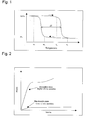
- the transformation occurs across a range of temperatures which are commonly named A s (start) and A f (finish) for the transformation from martensitic to austenitic state and M s (start) and M f (finish) for the transformation from austenitic to martensitic state as referenced in figure 1.
- These transformations are reversible so that the material may be treated to assume different shapes in each of the two phases, and can reversibly switch between the two shapes when transformed from one state to the other. More commonly, the material is treated to only return to a shape upon transformation to the austenitic phase a biasing force, acting against the SMA material returns it to its alternate shape upon transformation to the martensitic phase.
- the elastic modulus of the SMA material depends on its metallurgical state.
- Figure 2 shows a typical stress-strain graph of a SMA material in both states. It appears clearly that the austenitic state has a higher elastic modulus than the martensitic state.
- the stress-strain curve is roughly linear and the Young's modulus corresponds to the slope of the curve in the initial loading region. For materials tested at temperatures just above the A f temperature, if the material is further deformed beyond this initial loading region, it will experience a stress-induced martensitic transformation.
- the point on the stress-strain curve at which the stress-induced martensitic transformation begins can be called the M s ⁇ .
- the elastic modulus In the martensitic state, the elastic modulus is lower than in the austenitic state, and the corresponding M s ⁇ (in this case, the stress required to rearrange the pre-existing martensitic phase) is also lower.
- the invention makes use of the change in mechanical properties (mainly Young's modulus) of an array of actuators in SMA material when a transition between the two metallurgical states occurs.
- the SMA material is preferably chosen within SMA materials having a working temperature corresponding to body temperature located between M s and A s .
- the material is stable in both states at rest. Heating the material above A f will transform it into austenite (higher modulus material). Cooling the material below M f will transform it into martensite (lower modulus material). While the effect is most pronounced with the temperature of use located between M s and A s , the effect can be observed to some extent at a number of temperatures in the broader range between M f and A f .
- TiNi (Nitinol) is a good choice for the actuating members of a valve according to the invention as it is biocompatible. Further, TiNi can be manufactured such that body temperature is located between M s and A s .
- Fine tuning the temperature cycle and the mechanical properties may be achieved by playing with the chemical composition and thermomechanical processing of the material.
- the micro valve object of the invention comprises an array of actuators or actuating members made of a SMA material that interact either directly with the fluid path or with an elastic mean, the tension of which being modified by said array of SMA actuators.
- the SMA material is selected to have two stable metallurgical states at the temperature of use, e.g., body temperature.
- the metallurgical state can be changed either by cooling or by heating the SMA actuator.
- One of the metallurgical states has a higher elastic-modulus, whereas the other state has a lower elastic modulus.
- the heating is obtained by circulating a current through or in the proximity of the SMA material (Joule effect).
- the cooling is achieved thanks to a Peltier cell or an array of Peltier cells integrated in the base plate of the valve, in the vicinity of the SMA actuators.
- the fluid path crosses a base plate 2 having an array of orifices 3, closed by the free extremity of a corresponding array of actuating members 1.
- the base plate 2 is preferably made of a glass type material like Pyrex for example.
- the geometry of the orifices 3 is identical across the array, which ensures that the resistance to fluid is the same for each single orifice 3.
- the array of actuating members 1 comprises, in this embodiment, an elongated body from which extend perpendicularly elongated actuating members. Some other configurations are of course possible.
- the actuating members 1 are made of SMA material, preferably TiNi, and their geometry is chosen so that each fluid path 3 can be considered as closed when the corresponding actuating member 1 is in the austenitic state and open in the martensitic state.
- a Peltier cell 4 is integrated in the base plate 2, and allows, once energised, the cooling of the array of actuating members 1.
- Each actuating member 1 may be heated individually by circulating an electrical current through the connectors 5 bounded to each of the actuating members 1.
- the valve setting is modified in the following manner. First, the temperature of the array of SMA actuating members 1 is decreased to a temperature substantially lower than M s (preferably below M f ) by energising the Peltier cell 4. This transforms all or part of the actuating members 1 to the martensitic state (lower modulus). Then, at least one actuating member is selected within the array and the temperature of all actuating members 1 except the previously selected is increased to a temperature substantially higher than A s (preferably above A f ) This is achieved by circulating an electrical current through the connectors 5 connected to the actuating members 1. Once the higher temperature is reached, all or part of the actuating members 1 are in the austenitic state (higher modulus) except the selected actuating member which remains all or partially in the martensitic state thus determining the opening pressure of the valve.
- the array of SMA actuators may be first heated to a temperature at which an austenitic transformation occurs and then at least one selected actuating member is cooled down to a temperature at which a martensitic transformation occurs.
- an array of Peltier cells is provided. Each Peltier cell forming the array being located in the vicinity of an actuating member so as to enable the individual cooling of each actuating member.
- each actuating member 1 forming the array can be adjusted for providing different opening pressure depending on which actuating member remains in the martensitic state.
- Figures 6, 7 and 8 depict another embodiment of a valve with an adjustable opening pressure.
- the base plate 2 has only one orifice 3 through which the fluid may flow.
- a ball 6 is maintained in the seat of the orifice 3 thanks to an elastic element like a flexible flat spring 7 for example.
- the spring 7 need not be made of a SMA material.
- An array of SMA actuating members 1 is arranged perpendicularly to the spring 7 and the free end of each actuating member 1 interacts with the spring 7.
- the length of the spring allowed to move freely is restricted.
- the force applied to the ball is determined by the tension of the spring 7 which varies with the metallurgical states of the actuating members 1.
- a Peltier cell is integrated in the base plate 2 in the vicinity of the SMA array of actuating members 1. Upon activation, the Peltier cell cools the array and all the actuating members 1 change to martensitic state. Each of the actuating members 1 may then be individually heated to a temperature at which an austenitic transformation occurs. This determines the length of activation of the spring 7 and therefore the opening pressure of the valve.
- a third embodiment of a valve according to the invention provides a valve with an adjustable resistance to flow.
- a circular base plate 9 comprises, on its periphery, an array of openings 10 through which a fluid may flow.
- An array of actuating members 11 is arranged on the base plate 9 so that the free end of each actuating member 11 closes a corresponding opening 10 of the base plate.
- the SMA actuating members 11 are preferably extending from the centre of the base plate 9 to the periphery of said plate.
- all the actuating members 11 have the same geometry but the geometry of the orifices 10 may differ in order to provide a range of different resistances to flow.
- a Peltier cell or an array of Peltier cells is integrated in the base plate 9, preferably in the centre of the base plate so as to enable cooling of the complete array of SMA actuating members 11.
- the setting or the actuating of the valve is similar to what has been disclosed in reference to the first embodiment at figure 3 to 5.
- FIG 11, 12 and 13 illustrate an implantable valve with adjustable opening pressure.
- the implantable valve comprises a valve assembly 12 according to one of the first or second embodiment disclosed above.
- a top cover 13 having a fluid outlet 14 is adapted to receive the valve assembly 12.
- An antenna 17 as well as the necessary electronic components 18 to power and control the valve assembly by telemetry are integrated on the bottom of the base plate of the valve assembly 12.
- a bottom cover 15 having a fluid inlet 16 and a leak tight compartment 19 for protecting the electronic components closes the structure.
- the user may then power the assembly by telemetry and select non-invasively the opening pressure from outside the body by firstly cooling the SMA array of actuating members 11 and then selectively heating by Joule effect one or more actuating members 11.
- the electronic components 18 integrate a feedback mechanism that can be used to confirm that the correct actuating member 11 or array of actuating members have been heated.
- a valve according to the invention may also be used in an implantable drug delivery pump.
- a few existing adjustable implantable pumps allow the user (patient and/or doctor) to select non-invasively a flow rate of chemicals to inject, thanks to an external programming unit.
- the existing devices can be divided in two main categories: the active or passive pumping mechanisms.
- a battery energises a pump that regulates the flow rate of chemicals.
- a pressure reservoir "pushes" the chemicals out of the pump.
- the later concept is very elegant since the pumping does not require energy. Nevertheless, the regulation of the fluid flow is ensured by a valve, the opening of which depends on the power delivered to the valve. Therefore, a battery is still required.
- valve according to the invention when used in an implantable adjustable pump, the energy consumption problem is solved, since energy is only required to change the flow setting of the pump.
- the implantable pump comprises a pressurised reservoir 20 that contains the drug substance to administrate.
- a valve assembly 21 as described with reference to the third embodiment shown in figures 9 and 10 constitutes the adjustable flow resistance valve of the pump.
- the bottom of the base plate of the valve assembly 21 incorporates electronic components and an antenna that are used to power and control the valve non invasively by telemetry.
- a leak tight cover 22 protects the bottom face of the base plate and the electronics components, avoiding contact with the pressurised liquid contained in the reservoir 20.
- a top cover 23 having a fluid outlet 24 closes the structure.
- the user may select the resistance of the valve from outside with a dedicated reading unit and therefore regulates the outflow of chemicals contained in the pressurised reservoir.
- valve has multi stable states, energy is only required to switch from one state to the other. No energy is needed to maintain a selected state.
- Each state can either correspond to a selected opening pressure or to a flow resistance, depending on the application.
- valve settings can be adjusted without a movement of any part. Only the elastic modulus of the material is modified and therefore the valve is less sensitive to blockage by clogs and other bio-substances.
- the energy required is the energy needed to power a Peltier cell, and the energy for heating the actuating members. This energy can be provided to the implantable device by telemetry avoiding the use of batteries.
- the choice of the SMA material is of importance. It must be chosen from the SMA materials that have two stable states at a temperature in the vicinity of the body temperature. Furthermore, the SMA material ideally should fulfill the following conditions. M s ⁇ T ⁇ A s where T is the temperature of the human body and an hysteresis ⁇ T, comprised between 10 and 40 degrees centigrade. TiNi (Nitinol) is a material that fulfills these requirements and which is also biocompatible.
Abstract
Description
- The present invention relates to a method of setting and/or actuating a multi-stable valve used in fluidic or in micro fluidic applications. Another object of the invention is an adjustable multi stable valve for use in medical devices implanted in a human body.
- More specifically, the invention relates to a micro valve having at least two stable states at operating temperature. An opening pressure and a resistance to fluid flow correspond to each state of the valve. The valve may be actuated non-invasively, by telemetry for example, thanks to an external device, providing an adjustable opening pressure valve or alternatively a valve assembly with adjustable resistance to flow.
- The valve object of the present invention has a wide range of applications in different fields (medical, hydraulics, micro-engineering, ...). For example, in the medical field related to the treatment of hydrocephalic patients, it is necessary to install a shunt system that derives the excess of liquid from the brain to the peritonea or to another cavity of the patient. Some existing shunt systems comprise an adjustable valve that allows the surgeon to modify non-invasively the valve opening pressure after implantation. These existing implantable valves for the treatment of hydrocephalic patients have successfully shown that the feature allowing the surgeon to adjust non-invasively the valve opening pressure after implantation is extremely useful. Nevertheless, there are some drawbacks associated with devices of this type that can be summarised as follows:
- These known implants do not provide the user with any feedback during or after adjustment of the valve opening pressure. Therefore, it might be necessary to take an X-ray for checking the valve setting. Furthermore, the valve can be misadjusted by strong magnetic fields, such as those generated by a permanent magnet found for example in magnetic resonance imaging devices.
- Finally the existing valves are sometimes blocked due to an accumulation of bio-substance on the mechanical parts of the valve mechanism.
- Some other known electromechanical or pneumatic valves require energy for remaining in one or more working positions and are not suitable for human or animal implantation due to their size and / or their lack of tightness. The valve object of the present invention overcomes the problems exposed above by providing a micro valve having at least two stable states at operating temperature. The valve according to the invention does not require energy at rest during normal operation and is insensitive to magnetic fields by design. Since the valve setting may be adjusted without mechanical movement of any parts, the valve is less sensitive to blockage due to an accumulation of bio substances.
- The actuation concept is based on temperature changes above and below body temperature. Energy is only required to change the valve from one state to the other. Valves for the treatment of hydrocephalic patients, as well as valves for all kind of implantable pumps constitute major applications of that concept that may be extended to other fields.
- A method for setting and actuating an implantable valve having the steps disclosed in
claim 1 as well as a micro valve having the characteristics recited inclaim 4 obviates the above mentioned drawbacks. - Further features and other objects and advantages of this invention will become clear from the following detailed description made with reference to the accompanying drawings illustrating in a schematic and non-limiting way three embodiments of a multi stable micro valve according to the invention and in which:
- Figure 1 is a graph showing the typical temperature hysteresis of shape memory alloy (SMA).
- Figure 2 is a graph showing the typical stress-strain characteristics of a shape memory alloy in each of its states.
- Figure 3 is a schematic perspective top view of a first embodiment of a micro valve according to the invention.
- Figure 4 is a bottom perspective view according to the first embodiment shown at figure 3.
- Figure 5 is cross sectional view of the first embodiment of the valve shown at figure 3.
- Figure 6 is a perspective top view of a second embodiment of a micro valve according to the invention.
- Figure 7 is perspective bottom view of the second embodiment depicted in figure 6.
- Figure 8 is schematic cross sectional view of the second embodiment depicted in figure 6.
- Figure 9 is schematic perspective top view of a third embodiment of a micro valve according to the invention.
- Figure 10 is a perspective bottom view of the third embodiment depicted in figure 9.
- Figure 11 is a perspective top view of an implantable assembly incorporating a valve according to the invention, the top cover being exploded.
- Figure 12 is a perspective view of the assembly depicted in figure 11 with the bottom cover exploded.
- Figure 13 is a bottom perspective view of the assembly shown at figures 11 and 12.
- Figure 14 is an exploded perspective view of an implantable pump embodying a valve according to the invention.
-
- In the following disclosure, reference will be made to shape memory alloys, hereafter called SMA material. The properties and characteristics of such materials are briefly described in the following.
- SMA material is characterised by reversible metallurgical phase transformations that are activated either by temperature change or by induced stress. Below a range of transition temperature, the material is in the martensitic state, whereas above that temperature range, the material is in the austenitic state. The transformation occurs across a range of temperatures which are commonly named As (start) and Af (finish) for the transformation from martensitic to austenitic state and Ms (start) and Mf (finish) for the transformation from austenitic to martensitic state as referenced in figure 1. These transformations are reversible so that the material may be treated to assume different shapes in each of the two phases, and can reversibly switch between the two shapes when transformed from one state to the other. More commonly, the material is treated to only return to a shape upon transformation to the austenitic phase a biasing force, acting against the SMA material returns it to its alternate shape upon transformation to the martensitic phase.
- Most of the temperature cycles of the SMA materials have a hysteresis ΔT, as illustrated on the graph of figure 1.
- The elastic modulus of the SMA material depends on its metallurgical state. Figure 2 shows a typical stress-strain graph of a SMA material in both states. It appears clearly that the austenitic state has a higher elastic modulus than the martensitic state. Upon initial loading, the stress-strain curve is roughly linear and the Young's modulus corresponds to the slope of the curve in the initial loading region. For materials tested at temperatures just above the Af temperature, if the material is further deformed beyond this initial loading region, it will experience a stress-induced martensitic transformation. The point on the stress-strain curve at which the stress-induced martensitic transformation begins can be called the Ms σ.
- In the martensitic state, the elastic modulus is lower than in the austenitic state, and the corresponding Ms σ (in this case, the stress required to rearrange the pre-existing martensitic phase) is also lower.
- The invention makes use of the change in mechanical properties (mainly Young's modulus) of an array of actuators in SMA material when a transition between the two metallurgical states occurs.
- For medical implantable devices, the SMA material is preferably chosen within SMA materials having a working temperature corresponding to body temperature located between Ms and As. In that case, the material is stable in both states at rest. Heating the material above Af will transform it into austenite (higher modulus material). Cooling the material below Mf will transform it into martensite (lower modulus material). While the effect is most pronounced with the temperature of use located between Ms and As, the effect can be observed to some extent at a number of temperatures in the broader range between Mf and Af.
- For example TiNi (Nitinol) is a good choice for the actuating members of a valve according to the invention as it is biocompatible. Further, TiNi can be manufactured such that body temperature is located between Ms and As. A TiNi material manufactured to meet this criterion might have the following characteristics: Martensitic transformation: Mf= 24°C, Ms= 36°C, Austenitic transformation: As = 54°C, Af=71°C, with a hysteresis : ΔT ∼ 35°C. Note that the transformation temperatures for a particular material also change with stress, so that the temperatures of the starting material must be selected to appropriately accommodate the variability due to the operating stresses of the particular application.
- Fine tuning the temperature cycle and the mechanical properties may be achieved by playing with the chemical composition and thermomechanical processing of the material.
- As it will be described in detail with reference to the figures, the micro valve object of the invention comprises an array of actuators or actuating members made of a SMA material that interact either directly with the fluid path or with an elastic mean, the tension of which being modified by said array of SMA actuators.
- The SMA material is selected to have two stable metallurgical states at the temperature of use, e.g., body temperature. The metallurgical state can be changed either by cooling or by heating the SMA actuator. One of the metallurgical states has a higher elastic-modulus, whereas the other state has a lower elastic modulus.
- The heating is obtained by circulating a current through or in the proximity of the SMA material (Joule effect). The cooling is achieved thanks to a Peltier cell or an array of Peltier cells integrated in the base plate of the valve, in the vicinity of the SMA actuators.
- With reference to figure 3,4 and 5, a first embodiment of a micro valve with adjustable opening pressure is illustrated.
- The fluid path crosses a
base plate 2 having an array oforifices 3, closed by the free extremity of a corresponding array of actuatingmembers 1. Thebase plate 2 is preferably made of a glass type material like Pyrex for example. The geometry of theorifices 3 is identical across the array, which ensures that the resistance to fluid is the same for eachsingle orifice 3. The array of actuatingmembers 1 comprises, in this embodiment, an elongated body from which extend perpendicularly elongated actuating members. Some other configurations are of course possible. Theactuating members 1 are made of SMA material, preferably TiNi, and their geometry is chosen so that eachfluid path 3 can be considered as closed when the corresponding actuatingmember 1 is in the austenitic state and open in the martensitic state. - A
Peltier cell 4 is integrated in thebase plate 2, and allows, once energised, the cooling of the array of actuatingmembers 1. - Each actuating
member 1 may be heated individually by circulating an electrical current through theconnectors 5 bounded to each of theactuating members 1. - The valve setting is modified in the following manner. First, the temperature of the array of
SMA actuating members 1 is decreased to a temperature substantially lower than Ms (preferably below Mf) by energising thePeltier cell 4. This transforms all or part of theactuating members 1 to the martensitic state (lower modulus). Then, at least one actuating member is selected within the array and the temperature of all actuatingmembers 1 except the previously selected is increased to a temperature substantially higher than As (preferably above Af) This is achieved by circulating an electrical current through theconnectors 5 connected to theactuating members 1. Once the higher temperature is reached, all or part of theactuating members 1 are in the austenitic state (higher modulus) except the selected actuating member which remains all or partially in the martensitic state thus determining the opening pressure of the valve. - As an alternative, the array of SMA actuators may be first heated to a temperature at which an austenitic transformation occurs and then at least one selected actuating member is cooled down to a temperature at which a martensitic transformation occurs. For implementing this alternate method, an array of Peltier cells is provided. Each Peltier cell forming the array being located in the vicinity of an actuating member so as to enable the individual cooling of each actuating member.
- The size and geometry of each actuating
member 1 forming the array can be adjusted for providing different opening pressure depending on which actuating member remains in the martensitic state. - Figures 6, 7 and 8 depict another embodiment of a valve with an adjustable opening pressure. The
base plate 2 has only oneorifice 3 through which the fluid may flow. Aball 6 is maintained in the seat of theorifice 3 thanks to an elastic element like a flexibleflat spring 7 for example. Thespring 7 need not be made of a SMA material. - An array of
SMA actuating members 1 is arranged perpendicularly to thespring 7 and the free end of each actuatingmember 1 interacts with thespring 7. Depending on the metallurgical state of theSMA actuating members 1, the length of the spring allowed to move freely is restricted. The force applied to the ball is determined by the tension of thespring 7 which varies with the metallurgical states of theactuating members 1. - A Peltier cell is integrated in the
base plate 2 in the vicinity of the SMA array of actuatingmembers 1. Upon activation, the Peltier cell cools the array and all theactuating members 1 change to martensitic state. Each of theactuating members 1 may then be individually heated to a temperature at which an austenitic transformation occurs. This determines the length of activation of thespring 7 and therefore the opening pressure of the valve. - With reference to figures 9 and 10, a third embodiment of a valve according to the invention is disclosed. This embodiment provides a valve with an adjustable resistance to flow. A
circular base plate 9 comprises, on its periphery, an array ofopenings 10 through which a fluid may flow. An array of actuatingmembers 11 is arranged on thebase plate 9 so that the free end of each actuatingmember 11 closes acorresponding opening 10 of the base plate. TheSMA actuating members 11 are preferably extending from the centre of thebase plate 9 to the periphery of said plate. - In this embodiment, all the
actuating members 11 have the same geometry but the geometry of theorifices 10 may differ in order to provide a range of different resistances to flow. A Peltier cell or an array of Peltier cells is integrated in thebase plate 9, preferably in the centre of the base plate so as to enable cooling of the complete array ofSMA actuating members 11. - The setting or the actuating of the valve is similar to what has been disclosed in reference to the first embodiment at figure 3 to 5.
- Figure 11, 12 and 13 illustrate an implantable valve with adjustable opening pressure. The implantable valve comprises a
valve assembly 12 according to one of the first or second embodiment disclosed above. Atop cover 13 having afluid outlet 14 is adapted to receive thevalve assembly 12. Anantenna 17 as well as the necessaryelectronic components 18 to power and control the valve assembly by telemetry are integrated on the bottom of the base plate of thevalve assembly 12. Abottom cover 15 having afluid inlet 16 and a leaktight compartment 19 for protecting the electronic components closes the structure. - The user may then power the assembly by telemetry and select non-invasively the opening pressure from outside the body by firstly cooling the SMA array of actuating
members 11 and then selectively heating by Joule effect one ormore actuating members 11. Theelectronic components 18 integrate a feedback mechanism that can be used to confirm that thecorrect actuating member 11 or array of actuating members have been heated. - A valve according to the invention may also be used in an implantable drug delivery pump. A few existing adjustable implantable pumps allow the user (patient and/or doctor) to select non-invasively a flow rate of chemicals to inject, thanks to an external programming unit. The existing devices can be divided in two main categories: the active or passive pumping mechanisms. In the first case, a battery energises a pump that regulates the flow rate of chemicals. In the second case, a pressure reservoir "pushes" the chemicals out of the pump. The later concept is very elegant since the pumping does not require energy. Nevertheless, the regulation of the fluid flow is ensured by a valve, the opening of which depends on the power delivered to the valve. Therefore, a battery is still required.
- Thanks to a valve according to the invention, when used in an implantable adjustable pump, the energy consumption problem is solved, since energy is only required to change the flow setting of the pump.
- In the current products, energy is required continuously to keep the valve open. An adjustable passive pressurised pump embodying a valve according to the invention will now be disclosed with reference to figure 14.
- The implantable pump comprises a pressurised
reservoir 20 that contains the drug substance to administrate. Avalve assembly 21 as described with reference to the third embodiment shown in figures 9 and 10 constitutes the adjustable flow resistance valve of the pump. The bottom of the base plate of thevalve assembly 21 incorporates electronic components and an antenna that are used to power and control the valve non invasively by telemetry. A leaktight cover 22 protects the bottom face of the base plate and the electronics components, avoiding contact with the pressurised liquid contained in thereservoir 20. Atop cover 23 having afluid outlet 24 closes the structure. - The user may select the resistance of the valve from outside with a dedicated reading unit and therefore regulates the outflow of chemicals contained in the pressurised reservoir.
- Many advantages are achieved with a valve according to the invention. Firstly, as the valve has multi stable states, energy is only required to switch from one state to the other. No energy is needed to maintain a selected state. Each state can either correspond to a selected opening pressure or to a flow resistance, depending on the application.
- Second, the valve settings can be adjusted without a movement of any part. Only the elastic modulus of the material is modified and therefore the valve is less sensitive to blockage by clogs and other bio-substances.
- The energy required is the energy needed to power a Peltier cell, and the energy for heating the actuating members. This energy can be provided to the implantable device by telemetry avoiding the use of batteries.
- For medical applications, and more particularly for implantable adjustable valves or pumps as previously described, the choice of the SMA material is of importance. It must be chosen from the SMA materials that have two stable states at a temperature in the vicinity of the body temperature. Furthermore, the SMA material ideally should fulfill the following conditions. Ms < T < As where T is the temperature of the human body and an hysteresis ΔT, comprised between 10 and 40 degrees centigrade. TiNi (Nitinol) is a material that fulfills these requirements and which is also biocompatible.
- It will be appreciated by persons skilled in the art that the present invention is not limited by what has been disclosed above, particularly with regards to the field of use of the valve which may be integrated in other fluidic devices. Furthermore, the present invention may include combinations and subcombinations of the various features disclosed as well as modifications and extensions thereof which fall under the scope of the following claims.
Claims (10)
- A method of setting and actuating an adjustable micro valve characterised in that it comprises the following stepscooling an array of actuating members made of SMA material, to a temperature equal or below the temperature at which a transformation from austenitic to martensitic state occurs so that the entire array of SMA actuating members is either fully or partially in the martensitic state,selecting at least one of the actuating members corresponding to a pre-determined opening pressure or resistance to flow,heating individually each of the actuating members except the previously selected member to a temperature equal or above to the temperature at which a transformation from the martensitic state to the austensitic state occurs.
- A method of setting and actuating an adjustable micro valve characterised in that it comprises the following stepsheating an array of actuating members made of SMA material, to a temperature equal or above the temperature at which a transformation from martensitic to austenitic state occurs so that the entire array of SMA actuating members is either fully or partially in the austenitic state,selecting at least one of the actuating members corresponding to a pre-determined opening pressure or resistance to flow,cooling individually the selected actuating members to a temperature equal or below to the temperature at which a transformation from the austenitic state to the martensitic state occurs.
- A method according to claim 1 or 2 characterised in that the actuating members are made of a SMA material having two stable states at body temperature and an hysteresis comprised between 10 and 40 degrees centigrade.
- An adjustable micro valve characterised in that it comprises a base element with at least one passage for the fluid flow, at least one array of actuating members made of a SMA material arranged on one of the base plate face and means for cooling said array of actuating members and in that it further comprises heating means for heating the actuating members.
- An adjustable micro valve according to claim 4, characterised in that it further comprises an elastic element securing a ball in the seat of an opening and in that the actuating members are conformed so that one of their free ends interacts with a portion of the elastic element allowing alteration of its elasticity.
- An adjustable micro valve according to claim 4, characterised in that the actuating members are conformed so that one of their free ends closes a corresponding orifice in the base element.
- An adjustable micro valve according to one of the claims 4 to 6, characterised in that the cooling means are constituted of at least one Peltier cell integrated in the base element in the vicinity of the array of SMA actuating members.
- An adjustable micro valve according to one of the claims 4 to 7 characterised in that the actuating members are made of TiNi.
- An implantable micro valve having an adjustable opening pressure characterised in that it comprises an upper cover having a fluid outlet and a bottom cover having a fluid inlet embodying a micro valve according to one of the claims 4 to 7 and in that if further comprises electronic means and an antenna for energising and controlling the actuation of the valve by telemetry thanks to an external unit.
- An implantable pump characterised in that it comprises an upper cover having a fluid outlet, a pressurised reservoir, a valve assembly according to claim 4 and in that it further comprises electronic means and an antenna for energising and controlling the actuation of the pump by telemetry thanks to an external unit.
Priority Applications (8)
| Application Number | Priority Date | Filing Date | Title |
|---|---|---|---|
| EP20010123923 EP1273808B1 (en) | 2001-07-02 | 2001-10-06 | Adjustable micro valve and method of setting and actuating it |
| AU2002341249A AU2002341249B2 (en) | 2001-10-06 | 2002-09-30 | Method of setting and actuating a multi-stable micro valve and adjustable micro valve |
| CA2462968A CA2462968C (en) | 2001-10-06 | 2002-09-30 | Method of setting and actuating a multi-stable micro valve and adjustable micro valve |
| PCT/IB2002/003999 WO2003031828A1 (en) | 2001-10-06 | 2002-09-30 | Method of setting and actuating a multi-stable micro valve and adjustable micro valve |
| JP2003534774A JP2005504939A (en) | 2001-10-06 | 2002-09-30 | How to set up and operate multi-stable and adjustable micro-valves |
| BRPI0213130-7A BR0213130B1 (en) | 2001-10-06 | 2002-09-30 | METHOD FOR ADJUSTING AN ADJUSTABLE MICROVALVE, ADJUSTABLE MICROVALVE, DEPLOYMENT MICROVALVE ARRANGEMENT AND DEPLOYMENT PUMP |
| US10/263,504 US6926246B2 (en) | 2001-10-06 | 2002-10-03 | Method of setting and actuating a multi-stable micro valve and adjustable micro valve |
| US11/159,856 US20050252553A1 (en) | 2001-10-06 | 2005-06-23 | Method of setting and actuating a multi-stable micro valve and adjustable micro valve |
Applications Claiming Priority (3)
| Application Number | Priority Date | Filing Date | Title |
|---|---|---|---|
| EP01116013 | 2001-07-02 | ||
| EP01116013 | 2001-07-02 | ||
| EP20010123923 EP1273808B1 (en) | 2001-07-02 | 2001-10-06 | Adjustable micro valve and method of setting and actuating it |
Publications (2)
| Publication Number | Publication Date |
|---|---|
| EP1273808A1 true EP1273808A1 (en) | 2003-01-08 |
| EP1273808B1 EP1273808B1 (en) | 2006-04-05 |
Family
ID=26076639
Family Applications (1)
| Application Number | Title | Priority Date | Filing Date |
|---|---|---|---|
| EP20010123923 Expired - Lifetime EP1273808B1 (en) | 2001-07-02 | 2001-10-06 | Adjustable micro valve and method of setting and actuating it |
Country Status (1)
| Country | Link |
|---|---|
| EP (1) | EP1273808B1 (en) |
Cited By (2)
| Publication number | Priority date | Publication date | Assignee | Title |
|---|---|---|---|---|
| WO2005035015A1 (en) * | 2003-09-17 | 2005-04-21 | Scimed Life Systems, Inc. | Fatigue resistant medical devices |
| US7665300B2 (en) | 2005-03-11 | 2010-02-23 | Massachusetts Institute Of Technology | Thin, flexible actuator array to produce complex shapes and force distributions |
Citations (7)
| Publication number | Priority date | Publication date | Assignee | Title |
|---|---|---|---|---|
| US5619177A (en) * | 1995-01-27 | 1997-04-08 | Mjb Company | Shape memory alloy microactuator having an electrostatic force and heating means |
| EP0778043A1 (en) * | 1995-12-04 | 1997-06-11 | Pacesetter AB | Guide wire unit with internal guide wire of shape memory alloy |
| DE19645725C1 (en) * | 1996-11-06 | 1997-12-11 | Sican F & E Gmbh Sibet | Implantable and controllable valve for medical use |
| US5697951A (en) * | 1996-04-25 | 1997-12-16 | Medtronic, Inc. | Implantable stimulation and drug infusion techniques |
| WO1999038551A1 (en) * | 1998-02-02 | 1999-08-05 | Medtronic, Inc. | Implantable drug infusion device having a safety valve |
| WO1999039118A1 (en) * | 1998-02-03 | 1999-08-05 | The Board Of Trustees Operating Michigan State University Et Al. | Thin film fluid control systems and method of fabricating the same |
| US6149123A (en) * | 1996-09-27 | 2000-11-21 | Redwood Microsystems, Inc. | Integrated electrically operable micro-valve |
-
2001
- 2001-10-06 EP EP20010123923 patent/EP1273808B1/en not_active Expired - Lifetime
Patent Citations (7)
| Publication number | Priority date | Publication date | Assignee | Title |
|---|---|---|---|---|
| US5619177A (en) * | 1995-01-27 | 1997-04-08 | Mjb Company | Shape memory alloy microactuator having an electrostatic force and heating means |
| EP0778043A1 (en) * | 1995-12-04 | 1997-06-11 | Pacesetter AB | Guide wire unit with internal guide wire of shape memory alloy |
| US5697951A (en) * | 1996-04-25 | 1997-12-16 | Medtronic, Inc. | Implantable stimulation and drug infusion techniques |
| US6149123A (en) * | 1996-09-27 | 2000-11-21 | Redwood Microsystems, Inc. | Integrated electrically operable micro-valve |
| DE19645725C1 (en) * | 1996-11-06 | 1997-12-11 | Sican F & E Gmbh Sibet | Implantable and controllable valve for medical use |
| WO1999038551A1 (en) * | 1998-02-02 | 1999-08-05 | Medtronic, Inc. | Implantable drug infusion device having a safety valve |
| WO1999039118A1 (en) * | 1998-02-03 | 1999-08-05 | The Board Of Trustees Operating Michigan State University Et Al. | Thin film fluid control systems and method of fabricating the same |
Cited By (2)
| Publication number | Priority date | Publication date | Assignee | Title |
|---|---|---|---|---|
| WO2005035015A1 (en) * | 2003-09-17 | 2005-04-21 | Scimed Life Systems, Inc. | Fatigue resistant medical devices |
| US7665300B2 (en) | 2005-03-11 | 2010-02-23 | Massachusetts Institute Of Technology | Thin, flexible actuator array to produce complex shapes and force distributions |
Also Published As
| Publication number | Publication date |
|---|---|
| EP1273808B1 (en) | 2006-04-05 |
Similar Documents
| Publication | Publication Date | Title |
|---|---|---|
| AU2002341249B2 (en) | Method of setting and actuating a multi-stable micro valve and adjustable micro valve | |
| AU2002341249A1 (en) | Method of setting and actuating a multi-stable micro valve and adjustable micro valve | |
| EP3654894B1 (en) | Adjustable flow glaucoma shunts | |
| JP5863238B2 (en) | Electrokinetic actuator for titrating fluid flow | |
| US5820589A (en) | Implantable non-invasive rate-adjustable pump | |
| EP2260892B1 (en) | Multireservoir implantable drug delivery pumps | |
| US6620151B2 (en) | Non-constant pressure infusion pump | |
| EP1058565B1 (en) | Implantable drug infusion device having a safety valve | |
| JP6002154B2 (en) | Adjustment of hydrocephalus shunt valve | |
| AU2002236842A1 (en) | Non-constant pressure infusion pump | |
| JPH074429B2 (en) | Constant pressure embedded pump reservoir | |
| JP2010507750A (en) | Wax micro actuator | |
| US6629954B1 (en) | Drug delivery pump with isolated hydraulic metering | |
| EP2307076B1 (en) | Mri compatible programmable valve pump | |
| EP2754935A1 (en) | Adjustable passive flow regulator | |
| EP1273808B1 (en) | Adjustable micro valve and method of setting and actuating it | |
| US9259530B2 (en) | Implantable infusion device | |
| DE60118540T2 (en) | Adjustable microvalve and method of adjustment and actuation | |
| US20040112989A1 (en) | Fluid delivery device having a thermal equilibrating element | |
| WO2023215461A1 (en) | Adjustable shunts with improved flow control and associated systems and methods | |
| JPH0984881A (en) | In-body burried-type dosing device |
Legal Events
| Date | Code | Title | Description |
|---|---|---|---|
| PUAI | Public reference made under article 153(3) epc to a published international application that has entered the european phase |
Free format text: ORIGINAL CODE: 0009012 |
|
| AK | Designated contracting states |
Kind code of ref document: A1 Designated state(s): AT BE CH CY DE DK ES FI FR GB GR IE IT LI LU MC NL PT SE TR |
|
| AX | Request for extension of the european patent |
Free format text: AL;LT;LV;MK;RO;SI |
|
| 17P | Request for examination filed |
Effective date: 20030605 |
|
| AKX | Designation fees paid |
Designated state(s): AT BE CH CY DE DK ES FI FR GB GR IE IT LI LU MC NL PT SE TR |
|
| 17Q | First examination report despatched |
Effective date: 20030930 |
|
| GRAP | Despatch of communication of intention to grant a patent |
Free format text: ORIGINAL CODE: EPIDOSNIGR1 |
|
| RAP1 | Party data changed (applicant data changed or rights of an application transferred) |
Owner name: MEDOS INTERNATIONAL S.A.R.L. |
|
| GRAS | Grant fee paid |
Free format text: ORIGINAL CODE: EPIDOSNIGR3 |
|
| GRAA | (expected) grant |
Free format text: ORIGINAL CODE: 0009210 |
|
| AK | Designated contracting states |
Kind code of ref document: B1 Designated state(s): AT BE CH CY DE DK ES FI FR GB GR IE IT LI LU MC NL PT SE TR |
|
| PG25 | Lapsed in a contracting state [announced via postgrant information from national office to epo] |
Ref country code: IT Free format text: LAPSE BECAUSE OF FAILURE TO SUBMIT A TRANSLATION OF THE DESCRIPTION OR TO PAY THE FEE WITHIN THE PRESCRIBED TIME-LIMIT;WARNING: LAPSES OF ITALIAN PATENTS WITH EFFECTIVE DATE BEFORE 2007 MAY HAVE OCCURRED AT ANY TIME BEFORE 2007. THE CORRECT EFFECTIVE DATE MAY BE DIFFERENT FROM THE ONE RECORDED. Effective date: 20060405 Ref country code: FI Free format text: LAPSE BECAUSE OF FAILURE TO SUBMIT A TRANSLATION OF THE DESCRIPTION OR TO PAY THE FEE WITHIN THE PRESCRIBED TIME-LIMIT Effective date: 20060405 |
|
| REG | Reference to a national code |
Ref country code: GB Ref legal event code: FG4D |
|
| REG | Reference to a national code |
Ref country code: CH Ref legal event code: EP |
|
| REG | Reference to a national code |
Ref country code: IE Ref legal event code: FG4D |
|
| REF | Corresponds to: |
Ref document number: 60118540 Country of ref document: DE Date of ref document: 20060518 Kind code of ref document: P |
|
| PG25 | Lapsed in a contracting state [announced via postgrant information from national office to epo] |
Ref country code: DK Free format text: LAPSE BECAUSE OF FAILURE TO SUBMIT A TRANSLATION OF THE DESCRIPTION OR TO PAY THE FEE WITHIN THE PRESCRIBED TIME-LIMIT Effective date: 20060705 Ref country code: SE Free format text: LAPSE BECAUSE OF FAILURE TO SUBMIT A TRANSLATION OF THE DESCRIPTION OR TO PAY THE FEE WITHIN THE PRESCRIBED TIME-LIMIT Effective date: 20060705 |
|
| PG25 | Lapsed in a contracting state [announced via postgrant information from national office to epo] |
Ref country code: ES Free format text: LAPSE BECAUSE OF FAILURE TO SUBMIT A TRANSLATION OF THE DESCRIPTION OR TO PAY THE FEE WITHIN THE PRESCRIBED TIME-LIMIT Effective date: 20060716 |
|
| REG | Reference to a national code |
Ref country code: CH Ref legal event code: NV Representative=s name: MICHELI & CIE INGENIEURS-CONSEILS |
|
| REG | Reference to a national code |
Ref country code: GR Ref legal event code: EP Ref document number: 20060402149 Country of ref document: GR |
|
| PG25 | Lapsed in a contracting state [announced via postgrant information from national office to epo] |
Ref country code: PT Free format text: LAPSE BECAUSE OF FAILURE TO SUBMIT A TRANSLATION OF THE DESCRIPTION OR TO PAY THE FEE WITHIN THE PRESCRIBED TIME-LIMIT Effective date: 20060905 |
|
| PGFP | Annual fee paid to national office [announced via postgrant information from national office to epo] |
Ref country code: MC Payment date: 20060927 Year of fee payment: 6 |
|
| ET | Fr: translation filed | ||
| PLBE | No opposition filed within time limit |
Free format text: ORIGINAL CODE: 0009261 |
|
| STAA | Information on the status of an ep patent application or granted ep patent |
Free format text: STATUS: NO OPPOSITION FILED WITHIN TIME LIMIT |
|
| 26N | No opposition filed |
Effective date: 20070108 |
|
| PG25 | Lapsed in a contracting state [announced via postgrant information from national office to epo] |
Ref country code: MC Free format text: LAPSE BECAUSE OF NON-PAYMENT OF DUE FEES Effective date: 20071031 |
|
| PG25 | Lapsed in a contracting state [announced via postgrant information from national office to epo] |
Ref country code: CY Free format text: LAPSE BECAUSE OF FAILURE TO SUBMIT A TRANSLATION OF THE DESCRIPTION OR TO PAY THE FEE WITHIN THE PRESCRIBED TIME-LIMIT Effective date: 20060405 |
|
| PGFP | Annual fee paid to national office [announced via postgrant information from national office to epo] |
Ref country code: AT Payment date: 20130926 Year of fee payment: 13 Ref country code: GB Payment date: 20131002 Year of fee payment: 13 Ref country code: CH Payment date: 20131014 Year of fee payment: 13 Ref country code: BE Payment date: 20131014 Year of fee payment: 13 Ref country code: FR Payment date: 20131009 Year of fee payment: 13 Ref country code: LU Payment date: 20131014 Year of fee payment: 13 Ref country code: IE Payment date: 20131010 Year of fee payment: 13 Ref country code: DE Payment date: 20131002 Year of fee payment: 13 |
|
| PGFP | Annual fee paid to national office [announced via postgrant information from national office to epo] |
Ref country code: NL Payment date: 20131010 Year of fee payment: 13 Ref country code: IT Payment date: 20131028 Year of fee payment: 13 |
|
| PGFP | Annual fee paid to national office [announced via postgrant information from national office to epo] |
Ref country code: GR Payment date: 20140923 Year of fee payment: 14 |
|
| PGFP | Annual fee paid to national office [announced via postgrant information from national office to epo] |
Ref country code: TR Payment date: 20140926 Year of fee payment: 14 |
|
| REG | Reference to a national code |
Ref country code: DE Ref legal event code: R119 Ref document number: 60118540 Country of ref document: DE |
|
| REG | Reference to a national code |
Ref country code: NL Ref legal event code: V1 Effective date: 20150501 |
|
| PG25 | Lapsed in a contracting state [announced via postgrant information from national office to epo] |
Ref country code: LU Free format text: LAPSE BECAUSE OF NON-PAYMENT OF DUE FEES Effective date: 20141006 |
|
| REG | Reference to a national code |
Ref country code: CH Ref legal event code: PL |
|
| REG | Reference to a national code |
Ref country code: AT Ref legal event code: MM01 Ref document number: 322625 Country of ref document: AT Kind code of ref document: T Effective date: 20141006 |
|
| GBPC | Gb: european patent ceased through non-payment of renewal fee |
Effective date: 20141006 |
|
| PG25 | Lapsed in a contracting state [announced via postgrant information from national office to epo] |
Ref country code: BE Free format text: LAPSE BECAUSE OF NON-PAYMENT OF DUE FEES Effective date: 20141031 |
|
| REG | Reference to a national code |
Ref country code: IE Ref legal event code: MM4A |
|
| PG25 | Lapsed in a contracting state [announced via postgrant information from national office to epo] |
Ref country code: LI Free format text: LAPSE BECAUSE OF NON-PAYMENT OF DUE FEES Effective date: 20141031 Ref country code: DE Free format text: LAPSE BECAUSE OF NON-PAYMENT OF DUE FEES Effective date: 20150501 Ref country code: CH Free format text: LAPSE BECAUSE OF NON-PAYMENT OF DUE FEES Effective date: 20141031 Ref country code: GB Free format text: LAPSE BECAUSE OF NON-PAYMENT OF DUE FEES Effective date: 20141006 |
|
| REG | Reference to a national code |
Ref country code: FR Ref legal event code: ST Effective date: 20150630 |
|
| PG25 | Lapsed in a contracting state [announced via postgrant information from national office to epo] |
Ref country code: NL Free format text: LAPSE BECAUSE OF NON-PAYMENT OF DUE FEES Effective date: 20150501 Ref country code: IT Free format text: LAPSE BECAUSE OF NON-PAYMENT OF DUE FEES Effective date: 20141006 Ref country code: AT Free format text: LAPSE BECAUSE OF NON-PAYMENT OF DUE FEES Effective date: 20141006 Ref country code: FR Free format text: LAPSE BECAUSE OF NON-PAYMENT OF DUE FEES Effective date: 20141031 |
|
| PG25 | Lapsed in a contracting state [announced via postgrant information from national office to epo] |
Ref country code: IE Free format text: LAPSE BECAUSE OF NON-PAYMENT OF DUE FEES Effective date: 20141006 |
|
| REG | Reference to a national code |
Ref country code: GR Ref legal event code: ML Ref document number: 20060402149 Country of ref document: GR Effective date: 20160506 |
|
| PG25 | Lapsed in a contracting state [announced via postgrant information from national office to epo] |
Ref country code: GR Free format text: LAPSE BECAUSE OF NON-PAYMENT OF DUE FEES Effective date: 20160506 |
|
| PG25 | Lapsed in a contracting state [announced via postgrant information from national office to epo] |
Ref country code: TR Free format text: LAPSE BECAUSE OF NON-PAYMENT OF DUE FEES Effective date: 20151006 |