EP1045338A1 - Electronic memory card with card security element - Google Patents
Electronic memory card with card security element Download PDFInfo
- Publication number
- EP1045338A1 EP1045338A1 EP00401021A EP00401021A EP1045338A1 EP 1045338 A1 EP1045338 A1 EP 1045338A1 EP 00401021 A EP00401021 A EP 00401021A EP 00401021 A EP00401021 A EP 00401021A EP 1045338 A1 EP1045338 A1 EP 1045338A1
- Authority
- EP
- European Patent Office
- Prior art keywords
- card
- electronic
- memory card
- card according
- electronic component
- Prior art date
- Legal status (The legal status is an assumption and is not a legal conclusion. Google has not performed a legal analysis and makes no representation as to the accuracy of the status listed.)
- Granted
Links
Images
Classifications
-
- G—PHYSICS
- G06—COMPUTING; CALCULATING OR COUNTING
- G06K—GRAPHICAL DATA READING; PRESENTATION OF DATA; RECORD CARRIERS; HANDLING RECORD CARRIERS
- G06K19/00—Record carriers for use with machines and with at least a part designed to carry digital markings
- G06K19/06—Record carriers for use with machines and with at least a part designed to carry digital markings characterised by the kind of the digital marking, e.g. shape, nature, code
- G06K19/067—Record carriers with conductive marks, printed circuits or semiconductor circuit elements, e.g. credit or identity cards also with resonating or responding marks without active components
- G06K19/07—Record carriers with conductive marks, printed circuits or semiconductor circuit elements, e.g. credit or identity cards also with resonating or responding marks without active components with integrated circuit chips
- G06K19/077—Constructional details, e.g. mounting of circuits in the carrier
- G06K19/07749—Constructional details, e.g. mounting of circuits in the carrier the record carrier being capable of non-contact communication, e.g. constructional details of the antenna of a non-contact smart card
- G06K19/07766—Constructional details, e.g. mounting of circuits in the carrier the record carrier being capable of non-contact communication, e.g. constructional details of the antenna of a non-contact smart card comprising at least a second communication arrangement in addition to a first non-contact communication arrangement
- G06K19/07769—Constructional details, e.g. mounting of circuits in the carrier the record carrier being capable of non-contact communication, e.g. constructional details of the antenna of a non-contact smart card comprising at least a second communication arrangement in addition to a first non-contact communication arrangement the further communication means being a galvanic interface, e.g. hybrid or mixed smart cards having a contact and a non-contact interface
-
- G—PHYSICS
- G06—COMPUTING; CALCULATING OR COUNTING
- G06K—GRAPHICAL DATA READING; PRESENTATION OF DATA; RECORD CARRIERS; HANDLING RECORD CARRIERS
- G06K19/00—Record carriers for use with machines and with at least a part designed to carry digital markings
- G06K19/06—Record carriers for use with machines and with at least a part designed to carry digital markings characterised by the kind of the digital marking, e.g. shape, nature, code
- G06K19/067—Record carriers with conductive marks, printed circuits or semiconductor circuit elements, e.g. credit or identity cards also with resonating or responding marks without active components
- G06K19/07—Record carriers with conductive marks, printed circuits or semiconductor circuit elements, e.g. credit or identity cards also with resonating or responding marks without active components with integrated circuit chips
- G06K19/072—Record carriers with conductive marks, printed circuits or semiconductor circuit elements, e.g. credit or identity cards also with resonating or responding marks without active components with integrated circuit chips the record carrier comprising a plurality of integrated circuit chips
-
- G—PHYSICS
- G06—COMPUTING; CALCULATING OR COUNTING
- G06K—GRAPHICAL DATA READING; PRESENTATION OF DATA; RECORD CARRIERS; HANDLING RECORD CARRIERS
- G06K19/00—Record carriers for use with machines and with at least a part designed to carry digital markings
- G06K19/06—Record carriers for use with machines and with at least a part designed to carry digital markings characterised by the kind of the digital marking, e.g. shape, nature, code
- G06K19/067—Record carriers with conductive marks, printed circuits or semiconductor circuit elements, e.g. credit or identity cards also with resonating or responding marks without active components
- G06K19/07—Record carriers with conductive marks, printed circuits or semiconductor circuit elements, e.g. credit or identity cards also with resonating or responding marks without active components with integrated circuit chips
- G06K19/073—Special arrangements for circuits, e.g. for protecting identification code in memory
- G06K19/07309—Means for preventing undesired reading or writing from or onto record carriers
- G06K19/07372—Means for preventing undesired reading or writing from or onto record carriers by detecting tampering with the circuit
-
- G—PHYSICS
- G06—COMPUTING; CALCULATING OR COUNTING
- G06K—GRAPHICAL DATA READING; PRESENTATION OF DATA; RECORD CARRIERS; HANDLING RECORD CARRIERS
- G06K19/00—Record carriers for use with machines and with at least a part designed to carry digital markings
- G06K19/06—Record carriers for use with machines and with at least a part designed to carry digital markings characterised by the kind of the digital marking, e.g. shape, nature, code
- G06K19/067—Record carriers with conductive marks, printed circuits or semiconductor circuit elements, e.g. credit or identity cards also with resonating or responding marks without active components
- G06K19/07—Record carriers with conductive marks, printed circuits or semiconductor circuit elements, e.g. credit or identity cards also with resonating or responding marks without active components with integrated circuit chips
- G06K19/077—Constructional details, e.g. mounting of circuits in the carrier
Definitions
- the present invention relates to a memory card electronic of the type comprising a card body produced in a plastic material and an electronic module comprising a tablet semiconductor and a plurality of electrical contact pads, these contact pads being intended to establish a contact and a connection ohmic between the electronic module of the card and a read-write which will be called reader later.
- the chip semiconductor is part of an electronic module.
- This module electronics constitute a mechanical assembly formed by ranges of electrical contact made on a printed circuit or consisting of a conductive frame, a semiconductor chip fixed on the back of the external areas of the module and the electrical connections between the external areas and the terminals of the chip.
- the chip is embedded in an insulating material.
- This electronic module is placed in a housed space in the body of the card and whose dimensions are generally higher than those of the electronic module.
- the electronic module is most often fixed in its housing by an adhesive material.
- the electronic module constitutes a mechanical assembly accessible from the outside of the card due to the presence of external contact pads which are exposed in the face external of the card body, it is relatively simple by destroying the card body to recover an intact electronic module.
- the electronic module is used to identify the wearer in a badge reader and a photograph of the legitimate holder attached tamper evident on the body of the card is used for visual identification of the porter by the supervisor.
- Possible fraud for such memory cards used as identification badge would consist of extracting from the body of a card authentic an electronic module containing information to identify a first authorized person and to set this module in another falsified card body comprising the photograph of a other unauthorized person.
- An object of the present invention is to provide a card to electronic memory that can be used as a sound identification badge holder that makes the fraud described above impossible.
- the memory card electronic of the type comprising a card body made of a material plastic, said body having two main faces and a module comprising a plurality of electrical contact pads and a pad semiconductor connected to said pads by means of ohmic connection, said card being intended to be inserted into a read-write device, characterized in that it further comprises an electronic component comprising memory circuits containing card identification information, said information being detectable when said card is inserted into said read / write device, said electronic component being completely embedded in the plastic material constituting the body of the menu.
- the electronic component which is preferably a chip semiconductor, in which the identification information is stored is completely embedded in the plastic material constituting the body of the card, it is impossible to extract this component without altering it or at least without risking altering the information that we have memorized in its electronic circuits.
- the card includes a module standard electronics that do not contain identifying information.
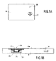
- FIGs 1a to 1c we will describe a first embodiment of the invention.
- the body 10 of the card made of plastic material as well as the standard electronic module 20 with its external contact pads electric 22, its semiconductor chip 24, the conductors electrical 26 for connecting the pad 24 to the contact pads 22 and a coating material 28.
- This electronic module is fixed by any suitable means in the body 10 of the card and its external contacts 22 are flush with the upper face 10a of the card body.
- the map also includes a second semiconductor chip or chip 30 which is completely embedded in the plastic material constituting the body card 10 and whose memory circuits contain information card identification.
- chip 30 is equipped with a coupling antenna electromagnetic with the reader.
- this antenna is constituted by a conductive deposit 32 made directly on the face upper 30a of the semiconductor wafer and connected to the terminals of this one. This embodiment simplifies the realization of the coupling antenna and therefore the entire card.
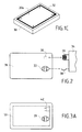
- Figure 2 illustrates the connections between reader 34 and the card referenced 36.
- the reader 34 must include ohmic contacts of the flexible blade type 38 for establishing an electrical connection with the external areas 22 of the card 36 and on the other hand an interface electromagnetic coupling 39 for exchanging information and for ensure the electrical supply of the semiconductor chip 30 by through its antenna 32.
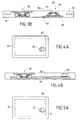
- FIGs 3a and 3b illustrate a second embodiment of the invention. It differs from the previous example by the realization of electronic component for storage of identification information and from its antenna.
- the second electronic component 40 consists of an electronic module 42 standard type with its semiconductor chip 44, these ranges conductive 46 and its electrical connections 48.
- the ranges of connection 46 are connected to an antenna 50 which is constituted by several conductive turns embedded in the semiconductor material constituting the card body 10 as is the second module electronic 42.
- This solution allows the use of two electronic modules of standard type, the second module more specifically having a function authentication of the card and, consequently, identification of its holder.
- This authentication or, more generally, identification function is made possible thanks to an authentication procedure implemented by electromagnetic coupling between the second module associated with its antenna and the terminal associated with its coupling interface electromagnetic and according to which the terminal sends for example a challenge à la carte, this challenge is received by the second module, the second module generates a coded response to this challenge using the information of identification contained in its memorization circuits and transmits this response to the terminal which decodes the response and validates it. In this sense, the credentials are detected by the reader.
- the second component electronics 40 has an antenna 50 which is completely embedded in the material constituting the body of the card. If we can extract the electronic component 40 of the card body, the antenna 50 will remain in the card body. However, this antenna is necessary for the reader to cards can access the identification information. The component electronics 40 cannot therefore be produced in another card.
- Figures 4a and 4b show another exemplary embodiment in which there is a standard electronic module 60, a chip semiconductor 62 embedded in the card body 10 and an antenna 64 embedded in the card body and connected to the chip 62. It will be noted, relative to this example, that extracting the body of the card from a flea embedded in this body is much more complex than extracting a standard electronic module.
- the electronic module is of the combined type, that is to say that the semiconductor chip is connected to both external pads of electrical contact and to an antenna and the additional chip is itself connected to an antenna.
- the implementation of the function identification can be carried out with a contactless reader, i.e. with electromagnetic coupling, the two semiconductor pads that can be used for identification. External contact ranges can be used in an ohmic reader when the identification function is not required.
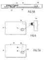
- FIGS 5a and 5b illustrate an exemplary embodiment of this variant.
- the card includes an electronic module 70 consisting by the semiconductor pad 72, and the external contact pads electric 74.
- the patch 72 is connected to an antenna 76 embedded in the card body 10.
- the second semiconductor chip 78 is embedded in the card body and also connected to the antenna 76.
- Figure 6 illustrates in a simplified way the connection between the card referenced 71 in FIGS. 6a, 6b and the reader 79.
- the reader only needs to be electromagnetic type.
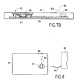
- FIGS. 7a and 7b another example of production of the card which is referenced 80.
- the card 80 includes a standard electronic module 82 consisting of the semiconductor chip 84 and the external contact pads 86.
- the card also includes a semiconductor chip 88 embedded in the card body and comprising identification information.
- the chip 88 is connected to the patch 84 by electrical conductors 90 embedded in the card body, these conductors forming address and data BUS lines for allow direct dialogue between the chip and the chip.
- FIG 8 there is shown in a simplified manner the reader 92 with which the card 80 is used.
- This reader is of course of the type with ohmic contacts 94 since the only interface of the card with the reader consists of the external electrical contact pads 86.
- the circuits of the pad 84 of the electronic module 82 are programmed so that, in the authentication phase, the information identification stored in chip 88 are temporarily transferred into the circuits of chip 84 in order to be compared with information entered in the reader 92.
- authentication of the component by the reader can require prior authentication of the patch by said component and that the authentication procedures carried out between the component and the lozenge can be mutual.
Abstract
Description
La présente invention a pour objet une carte à mémoire électronique du type comprenant un corps de carte réalisé dans un matériau plastique et un module électronique comprenant une pastille semi-conductrice et une pluralité de plages de contacts électriques, ces plages de contact étant destinées à établir un contact et une liaison ohmique entre le module électronique de la carte et un dispositif de lecture-écriture qui sera appelé ultérieurement lecteur.The present invention relates to a memory card electronic of the type comprising a card body produced in a plastic material and an electronic module comprising a tablet semiconductor and a plurality of electrical contact pads, these contact pads being intended to establish a contact and a connection ohmic between the electronic module of the card and a read-write which will be called reader later.
Dans les cartes à mémoire électronique standards, la puce semi-conductrice fait partie d'un module électronique. Ce module électronique constitue un ensemble mécanique formé par des plages externes de contact électrique réalisées sur un circuit imprimé ou constitué par un cadre conducteur, une puce semi-conductrice fixée sur le dos des plages externes du module et des connexions électriques entre les plages externes et les bornes de la puce. En outre, le plus souvent, la puce est enrobée dans un matériau isolant.In standard electronic memory cards, the chip semiconductor is part of an electronic module. This module electronics constitute a mechanical assembly formed by ranges of electrical contact made on a printed circuit or consisting of a conductive frame, a semiconductor chip fixed on the back of the external areas of the module and the electrical connections between the external areas and the terminals of the chip. In addition, most often, the chip is embedded in an insulating material.
Ce module électronique est placé dans un logement ménagé dans le corps de la carte et dont les dimensions sont en général supérieures à celles du module électronique. Le module électronique est fixé, le plus souvent, dans son logement par un matériau adhésif.This electronic module is placed in a housed space in the body of the card and whose dimensions are generally higher than those of the electronic module. The electronic module is most often fixed in its housing by an adhesive material.
Compte tenu du fait que le module électronique constitue un ensemble mécanique accessible de l'extérieur de la carte en raison de la présence des plages de contact externes qui affleurent dans la face externe du corps de carte, il est relativement simple par destruction du corps de la carte de récupérer un module électronique intact.Taking into account that the electronic module constitutes a mechanical assembly accessible from the outside of the card due to the presence of external contact pads which are exposed in the face external of the card body, it is relatively simple by destroying the card body to recover an intact electronic module.
Dans le cas de cartes à mémoire utilisées comme "badge" d'identification, le module électronique sert à l'identification du porteur dans un lecteur de badge et une photographie du détenteur légitime fixée de façon inviolable sur le corps de la carte sert à l'identification visuelle du porteur par le préposé à la surveillance.In the case of memory cards used as a "badge" identification, the electronic module is used to identify the wearer in a badge reader and a photograph of the legitimate holder attached tamper evident on the body of the card is used for visual identification of the porter by the supervisor.
Une fraude possible pour de telles cartes à mémoire servant de badge d'identification consisterait à extraire du corps d'une carte authentique un module électronique comportant des informations d'identification d'une première personne autorisée et à fixer ce module dans un autre corps de carte falsifié comportant la photographie d'une autre personne non autorisée.Possible fraud for such memory cards used as identification badge would consist of extracting from the body of a card authentic an electronic module containing information to identify a first authorized person and to set this module in another falsified card body comprising the photograph of a other unauthorized person.
Un objet de la présente invention est de fournir une carte à mémoire électronique pouvant servir de badge d'identification de son détenteur qui rende impossible la fraude décrite ci-dessus.An object of the present invention is to provide a card to electronic memory that can be used as a sound identification badge holder that makes the fraud described above impossible.
Pour atteindre ce but selon l'invention, la carte à mémoire électronique du type comprenant un corps de carte réalisé en un matériau plastique, ledit corps présentant deux faces principales et un module comprenant une pluralité de plages de contact électrique et une pastille semi-conductrice raccordée auxdites plages par des moyens de connexion ohmique, ladite carte étant destinée à être insérée dans un dispositif de lecture-écriture, caractérisée en ce qu'elle comprend en outre un composant électronique comportant des circuits de mémorisation contenant des informations d'identification de la carte, lesdites informations étant détectables lorsque ladite carte est insérée dans ledit dispositif de lecture/écriture, ledit composant électronique étant entièrement noyé dans le matériau plastique constituant le corps de la carte.To achieve this object according to the invention, the memory card electronic of the type comprising a card body made of a material plastic, said body having two main faces and a module comprising a plurality of electrical contact pads and a pad semiconductor connected to said pads by means of ohmic connection, said card being intended to be inserted into a read-write device, characterized in that it further comprises an electronic component comprising memory circuits containing card identification information, said information being detectable when said card is inserted into said read / write device, said electronic component being completely embedded in the plastic material constituting the body of the menu.
On comprend que grâce aux dispositions de l'invention, selon lesquelles le composant électronique, qui est de préférence une puce semi-conductrice, dans lequel sont mémorisées les informations d'identification est entièrement noyé dans le matériau plastique constituant le corps de la carte, il est impossible d'extraire ce composant sans l'altérer ou au moins sans risquer d'altérer les informations que l'on a mémorisées dans ses circuits électroniques. En outre, la carte comporte un module électronique standard qui ne contient pas les informations d'identification.It is understood that thanks to the provisions of the invention, according to which the electronic component, which is preferably a chip semiconductor, in which the identification information is stored is completely embedded in the plastic material constituting the body of the card, it is impossible to extract this component without altering it or at least without risking altering the information that we have memorized in its electronic circuits. In addition, the card includes a module standard electronics that do not contain identifying information.
D'autres caractéristiques et avantages de l'invention
apparaítront mieux à la lecture de la description qui suit de plusieurs
modes de mise en oeuvre de l'invention donnés à titre d'exemples non
limitatifs.
En se référant maintenant aux figures 1a à 1c, on va décrire un
premier mode de réalisation de l'invention. Sur les figures 2a et 2b, on a
représenté le corps 10 de la carte réalisé en matériau plastique ainsi que
le module électronique standard 20 avec ses plages externes de contact
électrique 22, sa pastille semi-conductrice 24, les conducteurs
électriques 26 de raccordement de la pastille 24 aux plages de contact 22
et un matériau d'enrobage 28. Ce module électronique est fixé par tout
moyen convenable dans le corps 10 de la carte et ses contacts externes
22 affleurent dans la face supérieure 10a du corps de carte. La carte
comporte également une deuxième pastille ou puce semi-conductrice 30
qui est entièrement noyée dans le matériau plastique constituant le corps
de carte 10 et dont les circuits de mémoire contiennent une information
d'identification de la carte.Referring now to Figures 1a to 1c, we will describe a
first embodiment of the invention. In Figures 2a and 2b, we have
represented the
Selon ce mode de réalisation, pour pouvoir dialoguer avec le
lecteur, la puce 30 est équipée d'une antenne de couplage
électromagnétique avec le lecteur. De préférence, cette antenne est
constituée par un dépôt conducteur 32 réalisé directement sur la face
supérieure 30a de la pastille semi-conductrice et reliée aux bornes de
celle-ci. Ce mode de réalisation permet de simplifier la réalisation de
l'antenne de couplage et donc l'ensemble de la carte.According to this embodiment, in order to be able to dialogue with the
reader,
Pour permettre l'obtention d'une puce entièrement noyée dans le corps de carte celui-ci peut être fabriqué par moulage par injection, la puce et les connexions électriques formant un insert dans le moule ou par laminage à chaud de deux feuilles de matériau plastique.To allow obtaining a chip completely embedded in the card body this can be made by injection molding, the chip and electrical connections forming an insert in the mold or by hot rolling two sheets of plastic material.
La figure 2 illustre les connexions entre le lecteur 34 et la carte
référencée 36. Le lecteur 34 doit comporter des contacts ohmiques du
type à lame flexible 38 pour établir une connexion électrique avec les
plages externes 22 de la carte 36 et d'autre part une interface de
couplage électromagnétique 39 pour échanger des informations et pour
assurer l'alimentation électrique de la puce semi-conductrice 30 par
l'intermédiaire de son antenne 32.Figure 2 illustrates the connections between
Dans ce mode de réalisation, on peut avoir une identification à
la fois par la puce 30 et par la pastille semi-conductrice 24 du module
électronique. On pourrait également n'utiliser que la liaison
électromagnétique avec la puce 30 pour assurer la fonction
d'authentification du porteur.In this embodiment, one can have an identification to
both by the
Les figures 3a et 3b illustrent un deuxième mode de réalisation
de l'invention. Il se distingue de l'exemple précèdent par la réalisation du
composant électronique de stockage des informations d'identification et
de son antenne. Comme le montre mieux la figure 3b, le deuxième
composant électronique 40 est constitué par un module électronique 42
de type standard avec sa pastille semi-conductrice 44, ces plages
conductrices 46 et ses connexions électriques 48. Les plages de
connexion 46 sont raccordées à une antenne 50 qui est constituée par
plusieurs spires conductrices noyées dans le matériau semi-conducteur
constituant le corps de carte 10 comme l'est le deuxième module
électronique 42.Figures 3a and 3b illustrate a second embodiment
of the invention. It differs from the previous example by the realization of
electronic component for storage of identification information and
from its antenna. As best shown in Figure 3b, the second
Cette solution permet d'utiliser deux modules électroniques de type standard, le second module ayant plus spécifiquement une fonction d'authentification de la carte et, par suite, d'identification de son porteur. Cette fonction d'authentification ou, plus généralement d'identification, est rendue possible grâce à une procédure d'authentification mise en oeuvre par couplage électromagnétique entre le second module associé à son antenne et le terminal associé à son interface de couplage électromagnétique et selon laquelle le terminal envoie par exemple un défi à la carte, ce défi est reçu par le second module, le second module génère une réponse codée à ce défi en utilisant les informations d'identification contenues dans ses circuits de mémorisation et transmet cette réponse au terminal qui décode la réponse et la valide. En ce sens, les informations d'identification sont détectées par le lecteur.This solution allows the use of two electronic modules of standard type, the second module more specifically having a function authentication of the card and, consequently, identification of its holder. This authentication or, more generally, identification function is made possible thanks to an authentication procedure implemented by electromagnetic coupling between the second module associated with its antenna and the terminal associated with its coupling interface electromagnetic and according to which the terminal sends for example a challenge à la carte, this challenge is received by the second module, the second module generates a coded response to this challenge using the information of identification contained in its memorization circuits and transmits this response to the terminal which decodes the response and validates it. In this sense, the credentials are detected by the reader.
Selon ce mode de réalisation, le deuxième composant
électronique 40 comporte une antenne 50 qui est entièrement noyée dans
le matériau constituant le corps de la carte. Si l'on peut extraire le
composant électronique 40 du corps de carte, l'antenne 50 restera dans le
corps de carte. Or, cette antenne est nécessaire pour que le lecteur de
cartes puisse avoir accès à l'information d'identification. Le composant
électronique 40 ne pourra donc être réalisé dans une autre carte.According to this embodiment, the
Les figures 4a et 4b montrent un autre exemple de réalisation
dans lequel on trouve un module électronique standard 60, une puce
semi-conductrice 62 noyée dans le corps de carte 10 et une antenne 64
noyée dans le corps de carte et raccordée à la puce 62. On notera,
relativement à cet exemple, que l'extraction du corps de la carte d'une
puce noyée dans ce corps est bien plus complexe que l'extraction d'un
module électronique standard.Figures 4a and 4b show another exemplary embodiment
in which there is a standard
Selon un autre exemple de mise en oeuvre du deuxième mode de réalisation, le module électronique est du type combiné, c'est-à-dire que la pastille semi-conductrice est reliée à la fois à des plages externes de contact électrique et à une antenne et la puce additionnelle est elle-même reliée à une antenne. La mise en oeuvre de la fonction d'identification peut être réalisée avec un lecteur sans contact, c'est-à-dire à couplage électromagnétique, les deux pastilles semi-conductrices pouvant être utilisées pour l'identification. Les plages externes de contact électrique peuvent être utilisées dans un lecteur ohmique lorsque la fonction d'identification n'est pas nécessaire.According to another example of implementation of the second mode embodiment, the electronic module is of the combined type, that is to say that the semiconductor chip is connected to both external pads of electrical contact and to an antenna and the additional chip is itself connected to an antenna. The implementation of the function identification can be carried out with a contactless reader, i.e. with electromagnetic coupling, the two semiconductor pads that can be used for identification. External contact ranges can be used in an ohmic reader when the identification function is not required.
Les figures 5a et 5b illustrent un exemple de réalisation de
cette variante. La carte comprend un module électronique 70 constitué
par la pastille semi-conductrice 72, et les plages externes de contact
électrique 74. De plus, la pastille 72 est raccordée à une antenne 76
noyée dans le corps de carte 10. La deuxième puce semi-conductrice 78
est noyée dans le corps de carte et également raccordée à l'antenne 76. Figures 5a and 5b illustrate an exemplary embodiment of
this variant. The card includes an electronic module 70 consisting
by the
La figure 6 illustre de façon simplifiée la liaison entre la carte
référencée 71 des figures 6a, 6b et le lecteur 79. Comme on l'a déjà
indiqué pour la fonction d'authentification, il suffit que le lecteur soit du
type électromagnétique.Figure 6 illustrates in a simplified way the connection between the card
referenced 71 in FIGS. 6a, 6b and the
On notera que, lorsque la puce et la pastille sont connectées à la même antenne, une collision est susceptible de se produire, la puce et la pastille répondant en effet de manière concomitante audit terminal. Cette collision est gérée selon des procédés connus de l'état de la technique tels que notamment décrits dans la norme ISO 14443 et de telle manière que soit la puce, soit la pastille, reste active. Il suffit alors que la puce et la pastille soient authentifiées par le terminal tour à tour pour que la carte soit considérée comme authentique. Bien entendu, compte tenu du fait que la puce et la pastille sont connectées en parallèle, les caractéristiques électromagnétiques du circuit composé de l'antenne et des deux puces sont modifiées. Aussi, de manière que le couplage inductif soit correctement assuré entre le terminal et la carte, les caractéristiques physiques de l'antenne sont avantageusement modifiées de sorte que l'impédance de ladite antenne soit divisée par deux.Note that when the chip and the chip are connected to the same antenna, a collision is likely to occur, the chip and the tablet responding in fact concomitantly to said terminal. This collision is managed according to methods known from the state of the art. techniques as described in particular in ISO 14443 and such so that either the chip or the pellet remains active. It is enough then that the chip and chip are authenticated by the terminal in turn so that the card is considered authentic. Of course, given because the chip and the pad are connected in parallel, the electromagnetic characteristics of the circuit composed of the antenna and of the two chips are changed. Also, so that the coupling is correctly ensured between the terminal and the card, physical characteristics of the antenna are advantageously modified so that the impedance of said antenna is halved.
Sur les figures 7a et 7b, on a représenté un autre exemple de
réalisation de la carte qui est référencée 80. La carte 80 comprend un
module électronique standard 82 constitué par la pastille semi-conductrice
84 et les plages externes de contact 86. La carte comprend également
une puce semi-conductrice 88 noyée dans le corps de carte et comportant
les informations d'identification. La puce 88 est reliée à la pastille 84 par
des conducteurs électriques 90 noyés dans le corps de carte, ces
conducteurs formant des lignes de BUS d'adresse et de données pour
permettre un dialogue direct entre la puce et la pastille.In FIGS. 7a and 7b, another example of
production of the card which is referenced 80. The
Sur la figure 8, on a représenté de façon simplifiée le lecteur 92
avec lequel est utilisée la carte 80. Ce lecteur est bien sûr du type à
contacts ohmiques 94 puisque la seule interface de la carte avec le
lecteur est constituée par les plages externes de contact électrique 86.In Figure 8, there is shown in a simplified manner the
Les circuits de la pastille 84 du module électronique 82 sont
programmés pour que, dans la phase d'authentification, les informations
d'identification stockées dans la puce 88 soient temporairement
transférées dans les circuits de la puce 84 en vue d'être comparées aux
informations introduites dans le lecteur 92. The circuits of the
En ce qui concerne les procédures d'authentification menées avec les cartes conformes à l'invention, les différents cas suivants sont susceptibles de se présenter :
- le composant électronique n'est pas connecté à une antenne. Il est alors connecté à la pastille et la procédure d'authentification est menée entre le dispositif de lecture-écriture et le composant par l'intermédiaire de la pastille, une authentification du composant par la pastille suite à une requête du dispositif de lecture-écriture suffisant cependant à authentifier la carte auprès dudit terminal, à moins que celui-ci n'exige une authentification complémentaire de ladite pastille.
- le composant électronique est connecté à une antenne et la procédure d'authentification est alors menée directement entre ledit composant et ledit dispositif de lecture-écriture, la carte étant réputée authentique si ledit composant est authentifié, à moins que le dispositif de lecture-écriture n'exige une authentification complémentaire de la pastille.
- the electronic component is not connected to an antenna. It is then connected to the patch and the authentication procedure is carried out between the read-write device and the component via the patch, an authentication of the component by the patch following a request from the read-write device. sufficient, however, to authenticate the card with said terminal, unless the latter requires additional authentication of said patch.
- the electronic component is connected to an antenna and the authentication procedure is then carried out directly between said component and said read-write device, the card being deemed authentic if said component is authenticated, unless the read-write device n 'requires additional authentication of the tablet.
A noter que l'authentification du composant par le lecteur peut nécessiter une authentification préalable de la pastille par ledit composant et que les procédures d'authentification menées entre le composant et la pastille peuvent être mutuelles.Note that authentication of the component by the reader can require prior authentication of the patch by said component and that the authentication procedures carried out between the component and the lozenge can be mutual.
Selon les résultats des authentifications, les transactions menées avec la carte et grâce au lecteur sont autorisées ou non.According to the authentication results, the transactions carried out with the card and thanks to the reader are authorized or not.
Il faut également ajouter que dans aucun cas les informations d'identification contenues dans le composant électronique ne sont directement accessibles par les plages de contact du module électronique.It should also be added that in no case the information identification contained in the electronic component are not directly accessible via the module's contact areas electronic.
Claims (12)
Applications Claiming Priority (2)
| Application Number | Priority Date | Filing Date | Title |
|---|---|---|---|
| FR9904520A FR2792091B1 (en) | 1999-04-12 | 1999-04-12 | SECURE ELECTRONIC MEMORY CARD |
| FR9904520 | 1999-04-12 |
Publications (2)
| Publication Number | Publication Date |
|---|---|
| EP1045338A1 true EP1045338A1 (en) | 2000-10-18 |
| EP1045338B1 EP1045338B1 (en) | 2011-10-19 |
Family
ID=9544270
Family Applications (1)
| Application Number | Title | Priority Date | Filing Date |
|---|---|---|---|
| EP20000401021 Expired - Lifetime EP1045338B1 (en) | 1999-04-12 | 2000-04-12 | Electronic memory card with card security element |
Country Status (2)
| Country | Link |
|---|---|
| EP (1) | EP1045338B1 (en) |
| FR (1) | FR2792091B1 (en) |
Cited By (3)
| Publication number | Priority date | Publication date | Assignee | Title |
|---|---|---|---|---|
| FR2823342A1 (en) * | 2001-04-10 | 2002-10-11 | Gemplus Card Int | ISO 7816 micro-chip card with high capacity data memory, data memory is placed off card principal flexion lines in cards neutral fiber |
| FR2877463A1 (en) * | 2004-11-03 | 2006-05-05 | Gemplus Sa | DEVICE HAVING AN ELECTRONIC MODULE |
| FR3088127A1 (en) * | 2018-11-06 | 2020-05-08 | Zakaria Ferhat | SMARTCARD |
Citations (5)
| Publication number | Priority date | Publication date | Assignee | Title |
|---|---|---|---|---|
| EP0326822A2 (en) * | 1988-02-01 | 1989-08-09 | Motorola Inc. | Data device module |
| US4857893A (en) * | 1986-07-18 | 1989-08-15 | Bi Inc. | Single chip transponder device |
| US5244840A (en) * | 1989-05-23 | 1993-09-14 | Mitsubishi Denki Kabushiki Kaisha | Method for manufacturing an encapsulated IC card having a molded frame and a circuit board |
| WO1997018531A1 (en) * | 1995-11-15 | 1997-05-22 | Solaic | Integrated circuit card and integrated circuit module |
| DE19621044A1 (en) * | 1996-05-24 | 1997-11-27 | Giesecke & Devrient Gmbh | Method for producing a card-shaped data carrier |
-
1999
- 1999-04-12 FR FR9904520A patent/FR2792091B1/en not_active Expired - Fee Related
-
2000
- 2000-04-12 EP EP20000401021 patent/EP1045338B1/en not_active Expired - Lifetime
Patent Citations (5)
| Publication number | Priority date | Publication date | Assignee | Title |
|---|---|---|---|---|
| US4857893A (en) * | 1986-07-18 | 1989-08-15 | Bi Inc. | Single chip transponder device |
| EP0326822A2 (en) * | 1988-02-01 | 1989-08-09 | Motorola Inc. | Data device module |
| US5244840A (en) * | 1989-05-23 | 1993-09-14 | Mitsubishi Denki Kabushiki Kaisha | Method for manufacturing an encapsulated IC card having a molded frame and a circuit board |
| WO1997018531A1 (en) * | 1995-11-15 | 1997-05-22 | Solaic | Integrated circuit card and integrated circuit module |
| DE19621044A1 (en) * | 1996-05-24 | 1997-11-27 | Giesecke & Devrient Gmbh | Method for producing a card-shaped data carrier |
Cited By (5)
| Publication number | Priority date | Publication date | Assignee | Title |
|---|---|---|---|---|
| FR2823342A1 (en) * | 2001-04-10 | 2002-10-11 | Gemplus Card Int | ISO 7816 micro-chip card with high capacity data memory, data memory is placed off card principal flexion lines in cards neutral fiber |
| WO2002084587A1 (en) * | 2001-04-10 | 2002-10-24 | Gemplus | Intelligent portable object with high storage capacity and locally controlled flexure |
| FR2877463A1 (en) * | 2004-11-03 | 2006-05-05 | Gemplus Sa | DEVICE HAVING AN ELECTRONIC MODULE |
| WO2006048380A1 (en) * | 2004-11-03 | 2006-05-11 | Gemplus | Device comprising a non-detachable electronic module |
| FR3088127A1 (en) * | 2018-11-06 | 2020-05-08 | Zakaria Ferhat | SMARTCARD |
Also Published As
| Publication number | Publication date |
|---|---|
| FR2792091A1 (en) | 2000-10-13 |
| EP1045338B1 (en) | 2011-10-19 |
| FR2792091B1 (en) | 2001-08-17 |
Similar Documents
| Publication | Publication Date | Title |
|---|---|---|
| EP0696010B2 (en) | Portable interface for electronic chip card | |
| EP0647943B1 (en) | Memory device | |
| FR2686172A1 (en) | CARD FOR MICROCOMPUTER FORMING CARD READER WITH FLOWING CONTACTS. | |
| EP2057588B1 (en) | Security peripheral integrated with a contactless object of secure document type with radiofrequency device | |
| EP2220597B1 (en) | System with dual integrated circuit and use of said system for implementing a remote application | |
| FR2670926A1 (en) | CHIP CARD READER, ESPECIALLY OF THE SUBSCRIBER IDENTIFICATION MODULE TYPE FOR RADIOTELEPHONE. | |
| US20070016963A1 (en) | PIN entry terminal having security system | |
| EP2241997B1 (en) | Memory card reader | |
| WO2001080173A1 (en) | Electronic label | |
| FR2653634A1 (en) | CHIP CARD SYSTEM PROVIDED WITH PORTABLE REMOTE ELECTRONICS. | |
| EP1045338B1 (en) | Electronic memory card with card security element | |
| WO2017077006A1 (en) | Memory card reader body with a protective mesh on both sides | |
| FR3113966A1 (en) | Personalization of a microcircuit card | |
| EP2239691A1 (en) | Unit with USB key including a chip card | |
| EP0676716A1 (en) | Portable digital information carrier | |
| FR2474204A1 (en) | Electronic personal identification card and reader - uses plastics card with integrated circuit memory and one giga hertz transmitter to communicate with reading appts. | |
| FR2821463A1 (en) | DEVICE FOR AUTHENTICATING MINERALOGIC PLATES | |
| EP2649777B1 (en) | Electronic payment device | |
| FR2948794A1 (en) | Microcircuit card i.e. identification card, for use in mobile network, has two external contact interfaces defining two surfaces formed on body, so that surfaces coincide partially along vertical direction | |
| WO2021014080A1 (en) | Electronic document module comprising a chip and a contact interface with an antenna connected to an i/o port of the chip, electronic document comprising such a module and method for checking a connection between the module and a corresponding antenna | |
| FR2722589A1 (en) | Portable interface for card with embedded electronic circuit | |
| EP2202677B1 (en) | Chip card and mobile terminal comprising such a card | |
| WO2002101641A1 (en) | Detachable chip card on support with pre-cut portion | |
| FR2968803A1 (en) | Electromagnetic transponder e.g. dual integrated circuit card, for contactless exchanging of protected data with reader for bank card, has electric circuit switched from one state to another state when resonant circuit is powered by reader | |
| CN111868729A (en) | Intrusion protected memory assembly |
Legal Events
| Date | Code | Title | Description |
|---|---|---|---|
| PUAI | Public reference made under article 153(3) epc to a published international application that has entered the european phase |
Free format text: ORIGINAL CODE: 0009012 |
|
| AK | Designated contracting states |
Kind code of ref document: A1 Designated state(s): DE ES FR GB IT NL |
|
| AX | Request for extension of the european patent |
Free format text: AL;LT;LV;MK;RO;SI |
|
| 17P | Request for examination filed |
Effective date: 20001104 |
|
| AKX | Designation fees paid |
Free format text: DE ES FR GB IT NL |
|
| RAP1 | Party data changed (applicant data changed or rights of an application transferred) |
Owner name: AXALTO S.A. |
|
| 17Q | First examination report despatched |
Effective date: 20071106 |
|
| RAP1 | Party data changed (applicant data changed or rights of an application transferred) |
Owner name: GEMALTO SA |
|
| GRAP | Despatch of communication of intention to grant a patent |
Free format text: ORIGINAL CODE: EPIDOSNIGR1 |
|
| GRAS | Grant fee paid |
Free format text: ORIGINAL CODE: EPIDOSNIGR3 |
|
| GRAA | (expected) grant |
Free format text: ORIGINAL CODE: 0009210 |
|
| AK | Designated contracting states |
Kind code of ref document: B1 Designated state(s): DE ES FR GB IT NL |
|
| REG | Reference to a national code |
Ref country code: GB Ref legal event code: FG4D Free format text: NOT ENGLISH |
|
| REG | Reference to a national code |
Ref country code: DE Ref legal event code: R096 Ref document number: 60046572 Country of ref document: DE Effective date: 20111222 |
|
| REG | Reference to a national code |
Ref country code: NL Ref legal event code: VDEP Effective date: 20111019 |
|
| PG25 | Lapsed in a contracting state [announced via postgrant information from national office to epo] |
Ref country code: NL Free format text: LAPSE BECAUSE OF FAILURE TO SUBMIT A TRANSLATION OF THE DESCRIPTION OR TO PAY THE FEE WITHIN THE PRESCRIBED TIME-LIMIT Effective date: 20111019 |
|
| PLBE | No opposition filed within time limit |
Free format text: ORIGINAL CODE: 0009261 |
|
| STAA | Information on the status of an ep patent application or granted ep patent |
Free format text: STATUS: NO OPPOSITION FILED WITHIN TIME LIMIT |
|
| PG25 | Lapsed in a contracting state [announced via postgrant information from national office to epo] |
Ref country code: IT Free format text: LAPSE BECAUSE OF FAILURE TO SUBMIT A TRANSLATION OF THE DESCRIPTION OR TO PAY THE FEE WITHIN THE PRESCRIBED TIME-LIMIT Effective date: 20111019 |
|
| 26N | No opposition filed |
Effective date: 20120720 |
|
| REG | Reference to a national code |
Ref country code: DE Ref legal event code: R097 Ref document number: 60046572 Country of ref document: DE Effective date: 20120720 |
|
| GBPC | Gb: european patent ceased through non-payment of renewal fee |
Effective date: 20120412 |
|
| PG25 | Lapsed in a contracting state [announced via postgrant information from national office to epo] |
Ref country code: GB Free format text: LAPSE BECAUSE OF NON-PAYMENT OF DUE FEES Effective date: 20120412 |
|
| PG25 | Lapsed in a contracting state [announced via postgrant information from national office to epo] |
Ref country code: ES Free format text: LAPSE BECAUSE OF FAILURE TO SUBMIT A TRANSLATION OF THE DESCRIPTION OR TO PAY THE FEE WITHIN THE PRESCRIBED TIME-LIMIT Effective date: 20120130 |
|
| REG | Reference to a national code |
Ref country code: FR Ref legal event code: PLFP Year of fee payment: 17 |
|
| REG | Reference to a national code |
Ref country code: FR Ref legal event code: PLFP Year of fee payment: 18 |
|
| REG | Reference to a national code |
Ref country code: FR Ref legal event code: PLFP Year of fee payment: 19 |
|
| PGFP | Annual fee paid to national office [announced via postgrant information from national office to epo] |
Ref country code: FR Payment date: 20190325 Year of fee payment: 20 |
|
| PGFP | Annual fee paid to national office [announced via postgrant information from national office to epo] |
Ref country code: DE Payment date: 20190220 Year of fee payment: 20 |
|
| REG | Reference to a national code |
Ref country code: DE Ref legal event code: R071 Ref document number: 60046572 Country of ref document: DE |