EP1042997B1 - Stent with variable wall thickness - Google Patents
Stent with variable wall thickness Download PDFInfo
- Publication number
- EP1042997B1 EP1042997B1 EP00302937A EP00302937A EP1042997B1 EP 1042997 B1 EP1042997 B1 EP 1042997B1 EP 00302937 A EP00302937 A EP 00302937A EP 00302937 A EP00302937 A EP 00302937A EP 1042997 B1 EP1042997 B1 EP 1042997B1
- Authority
- EP
- European Patent Office
- Prior art keywords
- stent
- struts
- thickness
- strut
- bands
- Prior art date
- Legal status (The legal status is an assumption and is not a legal conclusion. Google has not performed a legal analysis and makes no representation as to the accuracy of the status listed.)
- Expired - Lifetime
Links
Images


Classifications
-
- A—HUMAN NECESSITIES
- A61—MEDICAL OR VETERINARY SCIENCE; HYGIENE
- A61F—FILTERS IMPLANTABLE INTO BLOOD VESSELS; PROSTHESES; DEVICES PROVIDING PATENCY TO, OR PREVENTING COLLAPSING OF, TUBULAR STRUCTURES OF THE BODY, e.g. STENTS; ORTHOPAEDIC, NURSING OR CONTRACEPTIVE DEVICES; FOMENTATION; TREATMENT OR PROTECTION OF EYES OR EARS; BANDAGES, DRESSINGS OR ABSORBENT PADS; FIRST-AID KITS
- A61F2/00—Filters implantable into blood vessels; Prostheses, i.e. artificial substitutes or replacements for parts of the body; Appliances for connecting them with the body; Devices providing patency to, or preventing collapsing of, tubular structures of the body, e.g. stents
- A61F2/82—Devices providing patency to, or preventing collapsing of, tubular structures of the body, e.g. stents
- A61F2/86—Stents in a form characterised by the wire-like elements; Stents in the form characterised by a net-like or mesh-like structure
- A61F2/90—Stents in a form characterised by the wire-like elements; Stents in the form characterised by a net-like or mesh-like structure characterised by a net-like or mesh-like structure
- A61F2/91—Stents in a form characterised by the wire-like elements; Stents in the form characterised by a net-like or mesh-like structure characterised by a net-like or mesh-like structure made from perforated sheet material or tubes, e.g. perforated by laser cuts or etched holes
- A61F2/915—Stents in a form characterised by the wire-like elements; Stents in the form characterised by a net-like or mesh-like structure characterised by a net-like or mesh-like structure made from perforated sheet material or tubes, e.g. perforated by laser cuts or etched holes with bands having a meander structure, adjacent bands being connected to each other
-
- A—HUMAN NECESSITIES
- A61—MEDICAL OR VETERINARY SCIENCE; HYGIENE
- A61F—FILTERS IMPLANTABLE INTO BLOOD VESSELS; PROSTHESES; DEVICES PROVIDING PATENCY TO, OR PREVENTING COLLAPSING OF, TUBULAR STRUCTURES OF THE BODY, e.g. STENTS; ORTHOPAEDIC, NURSING OR CONTRACEPTIVE DEVICES; FOMENTATION; TREATMENT OR PROTECTION OF EYES OR EARS; BANDAGES, DRESSINGS OR ABSORBENT PADS; FIRST-AID KITS
- A61F2/00—Filters implantable into blood vessels; Prostheses, i.e. artificial substitutes or replacements for parts of the body; Appliances for connecting them with the body; Devices providing patency to, or preventing collapsing of, tubular structures of the body, e.g. stents
- A61F2/95—Instruments specially adapted for placement or removal of stents or stent-grafts
- A61F2/958—Inflatable balloons for placing stents or stent-grafts
-
- A—HUMAN NECESSITIES
- A61—MEDICAL OR VETERINARY SCIENCE; HYGIENE
- A61F—FILTERS IMPLANTABLE INTO BLOOD VESSELS; PROSTHESES; DEVICES PROVIDING PATENCY TO, OR PREVENTING COLLAPSING OF, TUBULAR STRUCTURES OF THE BODY, e.g. STENTS; ORTHOPAEDIC, NURSING OR CONTRACEPTIVE DEVICES; FOMENTATION; TREATMENT OR PROTECTION OF EYES OR EARS; BANDAGES, DRESSINGS OR ABSORBENT PADS; FIRST-AID KITS
- A61F2/00—Filters implantable into blood vessels; Prostheses, i.e. artificial substitutes or replacements for parts of the body; Appliances for connecting them with the body; Devices providing patency to, or preventing collapsing of, tubular structures of the body, e.g. stents
- A61F2/82—Devices providing patency to, or preventing collapsing of, tubular structures of the body, e.g. stents
- A61F2/86—Stents in a form characterised by the wire-like elements; Stents in the form characterised by a net-like or mesh-like structure
- A61F2/90—Stents in a form characterised by the wire-like elements; Stents in the form characterised by a net-like or mesh-like structure characterised by a net-like or mesh-like structure
- A61F2/91—Stents in a form characterised by the wire-like elements; Stents in the form characterised by a net-like or mesh-like structure characterised by a net-like or mesh-like structure made from perforated sheet material or tubes, e.g. perforated by laser cuts or etched holes
- A61F2/915—Stents in a form characterised by the wire-like elements; Stents in the form characterised by a net-like or mesh-like structure characterised by a net-like or mesh-like structure made from perforated sheet material or tubes, e.g. perforated by laser cuts or etched holes with bands having a meander structure, adjacent bands being connected to each other
- A61F2002/91525—Stents in a form characterised by the wire-like elements; Stents in the form characterised by a net-like or mesh-like structure characterised by a net-like or mesh-like structure made from perforated sheet material or tubes, e.g. perforated by laser cuts or etched holes with bands having a meander structure, adjacent bands being connected to each other within the whole structure different bands showing different meander characteristics, e.g. frequency or amplitude
-
- A—HUMAN NECESSITIES
- A61—MEDICAL OR VETERINARY SCIENCE; HYGIENE
- A61F—FILTERS IMPLANTABLE INTO BLOOD VESSELS; PROSTHESES; DEVICES PROVIDING PATENCY TO, OR PREVENTING COLLAPSING OF, TUBULAR STRUCTURES OF THE BODY, e.g. STENTS; ORTHOPAEDIC, NURSING OR CONTRACEPTIVE DEVICES; FOMENTATION; TREATMENT OR PROTECTION OF EYES OR EARS; BANDAGES, DRESSINGS OR ABSORBENT PADS; FIRST-AID KITS
- A61F2/00—Filters implantable into blood vessels; Prostheses, i.e. artificial substitutes or replacements for parts of the body; Appliances for connecting them with the body; Devices providing patency to, or preventing collapsing of, tubular structures of the body, e.g. stents
- A61F2/82—Devices providing patency to, or preventing collapsing of, tubular structures of the body, e.g. stents
- A61F2/86—Stents in a form characterised by the wire-like elements; Stents in the form characterised by a net-like or mesh-like structure
- A61F2/90—Stents in a form characterised by the wire-like elements; Stents in the form characterised by a net-like or mesh-like structure characterised by a net-like or mesh-like structure
- A61F2/91—Stents in a form characterised by the wire-like elements; Stents in the form characterised by a net-like or mesh-like structure characterised by a net-like or mesh-like structure made from perforated sheet material or tubes, e.g. perforated by laser cuts or etched holes
- A61F2/915—Stents in a form characterised by the wire-like elements; Stents in the form characterised by a net-like or mesh-like structure characterised by a net-like or mesh-like structure made from perforated sheet material or tubes, e.g. perforated by laser cuts or etched holes with bands having a meander structure, adjacent bands being connected to each other
- A61F2002/91533—Stents in a form characterised by the wire-like elements; Stents in the form characterised by a net-like or mesh-like structure characterised by a net-like or mesh-like structure made from perforated sheet material or tubes, e.g. perforated by laser cuts or etched holes with bands having a meander structure, adjacent bands being connected to each other characterised by the phase between adjacent bands
- A61F2002/91541—Adjacent bands are arranged out of phase
-
- A—HUMAN NECESSITIES
- A61—MEDICAL OR VETERINARY SCIENCE; HYGIENE
- A61F—FILTERS IMPLANTABLE INTO BLOOD VESSELS; PROSTHESES; DEVICES PROVIDING PATENCY TO, OR PREVENTING COLLAPSING OF, TUBULAR STRUCTURES OF THE BODY, e.g. STENTS; ORTHOPAEDIC, NURSING OR CONTRACEPTIVE DEVICES; FOMENTATION; TREATMENT OR PROTECTION OF EYES OR EARS; BANDAGES, DRESSINGS OR ABSORBENT PADS; FIRST-AID KITS
- A61F2/00—Filters implantable into blood vessels; Prostheses, i.e. artificial substitutes or replacements for parts of the body; Appliances for connecting them with the body; Devices providing patency to, or preventing collapsing of, tubular structures of the body, e.g. stents
- A61F2/82—Devices providing patency to, or preventing collapsing of, tubular structures of the body, e.g. stents
- A61F2/86—Stents in a form characterised by the wire-like elements; Stents in the form characterised by a net-like or mesh-like structure
- A61F2/90—Stents in a form characterised by the wire-like elements; Stents in the form characterised by a net-like or mesh-like structure characterised by a net-like or mesh-like structure
- A61F2/91—Stents in a form characterised by the wire-like elements; Stents in the form characterised by a net-like or mesh-like structure characterised by a net-like or mesh-like structure made from perforated sheet material or tubes, e.g. perforated by laser cuts or etched holes
- A61F2/915—Stents in a form characterised by the wire-like elements; Stents in the form characterised by a net-like or mesh-like structure characterised by a net-like or mesh-like structure made from perforated sheet material or tubes, e.g. perforated by laser cuts or etched holes with bands having a meander structure, adjacent bands being connected to each other
- A61F2002/9155—Adjacent bands being connected to each other
- A61F2002/91558—Adjacent bands being connected to each other connected peak to peak
-
- A—HUMAN NECESSITIES
- A61—MEDICAL OR VETERINARY SCIENCE; HYGIENE
- A61F—FILTERS IMPLANTABLE INTO BLOOD VESSELS; PROSTHESES; DEVICES PROVIDING PATENCY TO, OR PREVENTING COLLAPSING OF, TUBULAR STRUCTURES OF THE BODY, e.g. STENTS; ORTHOPAEDIC, NURSING OR CONTRACEPTIVE DEVICES; FOMENTATION; TREATMENT OR PROTECTION OF EYES OR EARS; BANDAGES, DRESSINGS OR ABSORBENT PADS; FIRST-AID KITS
- A61F2/00—Filters implantable into blood vessels; Prostheses, i.e. artificial substitutes or replacements for parts of the body; Appliances for connecting them with the body; Devices providing patency to, or preventing collapsing of, tubular structures of the body, e.g. stents
- A61F2/82—Devices providing patency to, or preventing collapsing of, tubular structures of the body, e.g. stents
- A61F2/86—Stents in a form characterised by the wire-like elements; Stents in the form characterised by a net-like or mesh-like structure
- A61F2/90—Stents in a form characterised by the wire-like elements; Stents in the form characterised by a net-like or mesh-like structure characterised by a net-like or mesh-like structure
- A61F2/91—Stents in a form characterised by the wire-like elements; Stents in the form characterised by a net-like or mesh-like structure characterised by a net-like or mesh-like structure made from perforated sheet material or tubes, e.g. perforated by laser cuts or etched holes
- A61F2/915—Stents in a form characterised by the wire-like elements; Stents in the form characterised by a net-like or mesh-like structure characterised by a net-like or mesh-like structure made from perforated sheet material or tubes, e.g. perforated by laser cuts or etched holes with bands having a meander structure, adjacent bands being connected to each other
- A61F2002/9155—Adjacent bands being connected to each other
- A61F2002/91575—Adjacent bands being connected to each other connected peak to trough
-
- A—HUMAN NECESSITIES
- A61—MEDICAL OR VETERINARY SCIENCE; HYGIENE
- A61F—FILTERS IMPLANTABLE INTO BLOOD VESSELS; PROSTHESES; DEVICES PROVIDING PATENCY TO, OR PREVENTING COLLAPSING OF, TUBULAR STRUCTURES OF THE BODY, e.g. STENTS; ORTHOPAEDIC, NURSING OR CONTRACEPTIVE DEVICES; FOMENTATION; TREATMENT OR PROTECTION OF EYES OR EARS; BANDAGES, DRESSINGS OR ABSORBENT PADS; FIRST-AID KITS
- A61F2250/00—Special features of prostheses classified in groups A61F2/00 - A61F2/26 or A61F2/82 or A61F9/00 or A61F11/00 or subgroups thereof
- A61F2250/0014—Special features of prostheses classified in groups A61F2/00 - A61F2/26 or A61F2/82 or A61F9/00 or A61F11/00 or subgroups thereof having different values of a given property or geometrical feature, e.g. mechanical property or material property, at different locations within the same prosthesis
- A61F2250/0018—Special features of prostheses classified in groups A61F2/00 - A61F2/26 or A61F2/82 or A61F9/00 or A61F11/00 or subgroups thereof having different values of a given property or geometrical feature, e.g. mechanical property or material property, at different locations within the same prosthesis differing in elasticity, stiffness or compressibility
-
- A—HUMAN NECESSITIES
- A61—MEDICAL OR VETERINARY SCIENCE; HYGIENE
- A61F—FILTERS IMPLANTABLE INTO BLOOD VESSELS; PROSTHESES; DEVICES PROVIDING PATENCY TO, OR PREVENTING COLLAPSING OF, TUBULAR STRUCTURES OF THE BODY, e.g. STENTS; ORTHOPAEDIC, NURSING OR CONTRACEPTIVE DEVICES; FOMENTATION; TREATMENT OR PROTECTION OF EYES OR EARS; BANDAGES, DRESSINGS OR ABSORBENT PADS; FIRST-AID KITS
- A61F2250/00—Special features of prostheses classified in groups A61F2/00 - A61F2/26 or A61F2/82 or A61F9/00 or A61F11/00 or subgroups thereof
- A61F2250/0014—Special features of prostheses classified in groups A61F2/00 - A61F2/26 or A61F2/82 or A61F9/00 or A61F11/00 or subgroups thereof having different values of a given property or geometrical feature, e.g. mechanical property or material property, at different locations within the same prosthesis
- A61F2250/0029—Special features of prostheses classified in groups A61F2/00 - A61F2/26 or A61F2/82 or A61F9/00 or A61F11/00 or subgroups thereof having different values of a given property or geometrical feature, e.g. mechanical property or material property, at different locations within the same prosthesis differing in bending or flexure capacity
-
- A—HUMAN NECESSITIES
- A61—MEDICAL OR VETERINARY SCIENCE; HYGIENE
- A61F—FILTERS IMPLANTABLE INTO BLOOD VESSELS; PROSTHESES; DEVICES PROVIDING PATENCY TO, OR PREVENTING COLLAPSING OF, TUBULAR STRUCTURES OF THE BODY, e.g. STENTS; ORTHOPAEDIC, NURSING OR CONTRACEPTIVE DEVICES; FOMENTATION; TREATMENT OR PROTECTION OF EYES OR EARS; BANDAGES, DRESSINGS OR ABSORBENT PADS; FIRST-AID KITS
- A61F2250/00—Special features of prostheses classified in groups A61F2/00 - A61F2/26 or A61F2/82 or A61F9/00 or A61F11/00 or subgroups thereof
- A61F2250/0014—Special features of prostheses classified in groups A61F2/00 - A61F2/26 or A61F2/82 or A61F9/00 or A61F11/00 or subgroups thereof having different values of a given property or geometrical feature, e.g. mechanical property or material property, at different locations within the same prosthesis
- A61F2250/0036—Special features of prostheses classified in groups A61F2/00 - A61F2/26 or A61F2/82 or A61F9/00 or A61F11/00 or subgroups thereof having different values of a given property or geometrical feature, e.g. mechanical property or material property, at different locations within the same prosthesis differing in thickness
Definitions
- This invention relates to stents.
- this invention relates to stents made more flexible, based on their overall structure; specifically, this invention relates to varying the wall thickness of a stent in order to create a more flexible stent; and also to improve radioopacity and alter other performance characteristics, such as radial strength, distension forces, etc. of the stent while not effecting its flexibility.
- a stent is commonly used as a tubular structure left inside the lumen of a vessel or duct of the body, in order to relieve an obstruction in the lumen or duct.
- stents are inserted into the lumen in their unexpanded form; the stents are then expanded on their own (or with the aid of a second device) in situ at the obstruction.
- a typical method of expansion occurs through the use of a catheter-mounted stent on an angioplasty balloon, which balloon is inflated within the stenosed vessel or body passageway. This inflation causes the obstructions of the vessel associated with the wall components of the vessel to compress. Thereafter, the stent holds the obstruction in place at the vessel wall, and an enlarged lumen is obtained.
- stents are a technology transforming the type of therapy used against stenosis of a lumen. That is, in the absence of a using a stent, (in other words, when a balloon used alone) restenosis often occurs, as a result of elastic recoil of the stenotic lesion away from the vessel wall. So, stents have been hailed as a breakthrough in the use of science to improve medicinal therapies.
- stent designs have been created, the designs of these stents have exhibited a number of limitations, such as a general restriction on the dimension of the stent. For instance, typical stents have been limited to a pair of generally rigid ends (approx. 8mm) and a flexible middle section (anywhere from about 7mm to about 21mm). This device is formed of multiple parts and is not continuously flexible along the longitudinal axis. Other stent designs with rigid segments and flexible segments have also been described.
- stents are described as longitudinally flexible, but consist of a plurality of cylindrical elements connected by flexible members.
- This design has at least one important disadvantage, for example, according to this design, protruding edges occur when the stent is flexed around a curve raising the possibility of inadvertent retention of the stent on plaque deposited on arterial walls. This may cause the stent to embolize or move out of position and further cause damage to the interior lining of healthy vessels.
- balloon expandable stents known in the art generally compromise axial flexibility to permit expansion and provide overall structural integrity.
- the flexibility of the stent along its length it is further more desirable to be able to vary the flexibility of the stent along its length.
- To be able to vary the flexibility of the stent along its length could provide for emplacement of the proximal end in a narrower or more tortuous coronary artery, while stabilizing the stent at its proximal end.
- EP-A-0 800 801 show a stent having variable flexibility along its lenght. This is achieved by making the end portions relatively thicker than the intermediaire portion.
- the present invention overcomes some perceived shortcomings of prior art stents by providing a stent with axial flexibility.
- the stent has a first end and a second end with an intermediate section between the two ends.
- the stent further has a longitudinal axis and comprises a plurality of longitudinally disposed bands, wherein each band defines a generally continuous wave along a line segment parallel to the longitudinal axis.
- a plurality of links maintains the bands in a tubular structure.
- each longitudinally disposed band of the stent is connected, at a plurality of periodic locations, by a short circumferential link to an adjacent band.
- the wave associated with each of the bands has approximately the same fundamental spatial frequency in the intermediate section, and the bands are so disposed that the waves associated with them are spatially aligned so as to be generally in phase with one another.
- the spatially aligned bands are connected, at a plurality of periodic locations, by a short circumferential link to an adjacent band.
- a common axial position occurs alternately in the first group and in the second group of axial positions. Then, the first and second sets are selected so that a given band is linked to a neighboring band at only one of the first and second groups of common axial positions.
- the spatial frequency of the wave associated with each of the bands is decreased in a first end region lying proximate to the first end and in a second end region lying proximate to the second end. By comparison this will make the ends of the stent "stiffer.”
- the spatial frequency of the bands in the first and second end regions is decreased by 20% compared with the spatial frequency of the bands in the intermediate section.
- the first end region may be located between the first end and a set of circumferential links lying closest to the first end and the second end region lies between the second end and a set of circumferential links lying closest to the second end.
- Each band includes a terminus at each of the first and second ends and the adjacent pairs of bands are joined at their termini to form a closed loop.
- a stent in a further embodiment of the invention, has first and second ends with an intermediate section between the two. This stent has further increased axial flexibility.
- This stent includes a plurality of longitudinally disposed bands, wherein each band defines a generally continuous wave having a spatial frequency along a line segment parallel to the longitudinal axis, the spatial frequency of the wave associated with each of the bands being decreased in a first end region lying proximate to the first end and in a second end region lying proximate to the second end, in comparison to the spatial frequency of the wave in the intermediate section; and a plurality of links for maintaining the bands in a tubular structure.
- the first and second regions have been further defined as the region that lies between the first and second ends and a set of circumferential links lying closest to the first end and second end.
- the widths of the sectionals of the bands, measured in a circumferential direction, are greater in the first and second end regions than in the intermediate section.
- the stent is divided into a group of segments. Each of the segments are connected by a flexible connector.
- the stent segments are provided with enhanced flexibility at the flexible connectors, due to the geometrical configuration of the flexible connectors.
- the stent being made flexible along its length.
- the stent initially starts as a metal sheet. It is rolled in its central region to a specified wall thickness. Thereafter, the stent is photochemically etched to produce the desired cell pattern of the design of the stent. Then, the stent is folded and the metal is joined to give rise to a stent with multiple wall thickness. For instance, larger wall thicknesses at the end of the stent versus smaller wall thicknesses at its center. Various other possible manufacturing methods are certainly perceived to be possible with respect to this stent. Alternately, the stent can be etched in its tubular configuration with the same desired effect.
- Improvements afforded by embodiments of the present invention include the following. First, there is an increased flexibility in two planes of the non-expanded stent while maintaining radial strength and a high percentage open area after expansion. Second, the stent of this invention provides even pressure on the expanding stent that ensures the consistent and continuous contact of expanded stent against artery wall. Third, the stent affords an avoidance of protruding parts during bending. Fourth, there is a removal of existing restrictions on maximum size of the stent. Fifth, the stent reduces any shortening effect during expansion of the stent.
- an expandable cylindrical stent 10 having a fenestrated structure for placement in a blood vessel, duct or lumen to hold the vessel, duct or lumen open, more particularly for protecting a segment of artery from restenosis after angioplasty.
- the stent 10 may be expanded circumferentially and maintained in an expanded, circumferentially rigid configuration.
- the stent 10 is axially flexible and when flexed at a band, the stent 10 avoids any externally protruding component parts.
- Figure 1 shows what happens to a stent 10, of a similar design to a preferred embodiment herein but utilizing instead a series of circumferentially disposed bands, when caused to bend in a manner that is likely encountered within a lumen of the body.
- a stent 10 with a circumferential arrangement of bands (1) experiences an effect analogous to a series of railroad cars on a track. As the row of railroad cars proceeds around the bend, the comer of each car proceeding around the bend after the coupling is caused to protrude from the contour of the track.
- the serpentine circumferential bands have a series of protrusions (2) above the surface of the stent 10 as the stent 10 bends.
- the novel design of a preferred embodiment is shown in Figures 1(c) and 1(d) and Figure 7.
- the bands (3) are axially flexible and are arranged along the longitudinal axis, avoids such an effect when the stent 10 is bent, so the bent bands (4) do not protrude from the profile of the curve of the stent 10.
- any flaring at the ends of the stent 10 that might occur with a stent 10 having a uniform structure is substantially eliminated by introducing a modification at the ends of the stent 10.
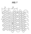
- This modification comprises decreasing the spatial frequency and increasing the width of the corresponding bands in a circumferential direction (L A and A) compared to that of the intermediate section. (I B and B).
- the spatial frequency L A may be decreased 0-50% with respect to L B , and the width A may be increased in the range of 0-150% with respect to B.
- Other modifications at the ends of the stent 10 may include increasing the thickness of the wall of the stent 10 and selective electropolishing. These modifications protect the artery and any plaque from abrasion that may be caused by the stent 10 ends during insertion of the stent 10. The modification also may provide increased radio-opacity at the ends of the stent 10. Hence it may be possible to more accurately locate the stent 10 once it is in place in the body.
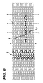
- the embodiment as shown in Figures 2 and 6 has the unique advantage of possessing effective "springs" in both circumferential and longitudinal directions shown as items (5) and (6) respectively. These springs provide the stent 10 with the flexibility necessary both to navigate vessels in the body with reduced friction and to expand at the selected site in a manner that provides the final necessary expanded dimensions without undue force while retaining structural resilience of the expanded structure.
- each longitudinal band undulates through approximately two cycles before there is formed a circumferential link to an adjacent band.
- each waveform W associated with each of the bands Prior to expansion, each waveform W associated with each of the bands will have approximately the same fundamental spatial frequency.
- the bands are so disposed that the wave W associated with them are spatially aligned, so as to be generally in phase with one another as shown in Figure 6.
- the aligned bands on the longitudinal axis are connected at a plurality of periodic locations, by a short circumferential link to an adjacent band.
- a first common axial position such as shown by the line X-X in Figures 4 and 6.
- an adjacent pair of bands is joined by circumferential link 7.
- other pairs of bands are also linked at this common axial position.
- a second common axial position shown in Figure 6 by the line Y-Y
- an adjacent pair of bands is joined by circumferential link 8.
- any given pair of bands that is linked at X-X is not linked at Y-Y and vice-versa.
- the X-X pattern of linkages repeats at the common axial position Z-Z.
- a feature of the expansion event is that the pattern of open space in the stent 10 of the embodiment of Figure 2 before expansion is different from the pattern of the stent 10 after expansion.
- the pattern of open space on the stent 10 before expansion is serpentine, whereas after expansion, the pattern approaches a diamond shape (3a, 3b).
- expansion may be achieved using pressure from an expanding balloon or by other mechanical means.
- FIG. 3 shows how radial expansion of the stent 10 causes the openings (or "fenestrations") to open up into a diamond shape with maximum stress being expended on the apices of the diamond along the longitudinal axis.
- finite element analyses including strain studies were performed on the stent 10, it was found that maximum strain was experienced on the bands and links and was below the maximum identified as necessary to maintain structural integrity.
- the optimization of strain of the stent 10 is achieved by creating as large a turn radius as possible in the wave W associated with each band in the non-expanded stent 10. This is accomplished while preserving a sufficient number of bands and links to preserve the structural integrity of the stent 10 after expansion.
- the strain may be less than 0.57 m/m (0.57 inches/inch) for 316L stainless steel.
- the expansion pressure may be 1.013 - 7.091 bar (1.0-7.0 atmospheres).
- the number of bands and the spatial frequency of the wave W on the longitudinal axis also affect the number of circumferential links.
- the circumferential links contribute structural integrity during application of radial force used in expansion of the stent 10 and in the maintenance of the expanded form.
- a stent 10 of the invention having a longitudinal axis and providing axial flexibility as described above is shown in Figure 6.
- This stent 10 has an expanded diameter of 4mm and a length of 30mm.
- it may have about 8-12 rows, more particularly 10 rows and about 6-10 slots, more particularly 8 slots (a slot is shown in Figure 6 as extending between X and Z).
- the stent may also have a wave W amplitude of about 1/4-1/10 of a slot length, more particularly 1/8 of a slot length.
- the stent 10 may be fabricated from many methods.
- the stent 10 may be fabricated from a hollow or formed stainless steel tube that may be cut out using lasers, electric discharge milling (EDM), chemical etching or other means.
- EDM electric discharge milling
- the stent 10 is inserted into the body and placed at the desired site in an unexpanded form.
- expansion of the stent 10 is effected in a blood vessel by means of a balloon catheter, where the final diameter of the stent 10 is a function of the diameter of the balloon catheter used.
- the stent 10 of the invention can be made at any desired length, most preferably at a nominal 30mm length that can be extended or diminished by increments, for example 1.9mm increments.
- a stent 10 in accordance with the present invention may be embodied in a shape memory material, including, for example, an appropriate alloy of nickel and titanium; or stainless steel.
- the stent 10 may be compressed so as to occupy a space sufficiently small as to permit its insertion in a blood vessel or other tissue by insertion means, wherein the insertion means include a suitable catheter, or flexible rod.
- the stent 10 On emerging from the catheter, the stent 10 may be configured to expand into the desired configuration where the expansion is automatic or triggered by a change in pressure, temperature or electrical stimulation.
- An embodiment of the improved stent 10 has utility not only within blood vessels as described above but also in any tubular system of the body such as the bile ducts, the urinary system, the digestive tube, and the tubes of the reproductive system in both men and women.
- a stent 10 as presently disclosed containing a multiplicity of curvilinear segments 20. These curvilinear segments 20 are connected to each other via a generally perpendicular connector 25.
- the generally perpendicular connector 25 lies substantially in the plane perpendicular to the longitudinal axis of the stent 10.
- Each of the stent 10 segments as described herein is connected to an adjacent stent 10 segment. This is done using a series of flexible connectors.
- the connectors themselves can be made narrower at their midpoints. This enhances the possibility of flexure at that point.
- alternate designs of the connector to insure flexibility are possible, and contemplated by this invention.
- the stent 10 as described in Figure 8 is a stent 10 of considerable flexibility when compared to more rigid rectilinear stents. Nonetheless, the stent 10 of the present invention does not depart from the basic concepts set forth herein, in that it discloses a continuously curvilinear strut. This curvilinear strut is connected to other curvilinear struts via a series of "second" (more flexible) connectors, as described above.
- the stent 10 of the present invention incorporates various new and useful members.
- One of them is the flexible connector in conjunction with a generally curvilinear stent.
- Another is the use of the generally larger struts at the ends of the stent 10 in order to provide for continued support at the stent 10 ends.
- a final aspect is the use of flexible connectors amongst stent 10 segments to provide for greater flexibility.
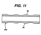
- the stents 200, 300 of Figure 9 and 11 each contain struts 50, 60. These struts 50,60 are, in typical stents, generally of uniform thickness. What may be desirable is to vary the thickness of the struts 50,60 so as to enhance flexibility of the stent.
- the stent initially starts out as a sheet S of metal. Then, the metal sheet S is rolled in the central region appearing between the two dotted lines to the specified wall thickness for the middle region of the stent. The rolling process produces a "texture" surface finish in the interior middle section of a stent.
- the stent sheet now has two wall thicknesses T, T'. One thickness T is contained at the proximal end of the stent. One thickness T is contained at the distal end of the stent. These typically kept the same. However, as can be seen better in Figure 10b, the thickness T' in the middle of the stent is now narrower.
- this particular stent when finally formed, will be more flexible in its middle sections, and more rigid in its distal and proximal ends. This may be desirable, for instance, where the stent is necessary to be "anchored” in the coronary artery or for ostial lesions. Thicker ends also allow for increased radioopacity at the ends.
- this present stent size presents particular advantage.
- the rolling process produces a textured surface in the interior middle section of the stent. This textured surface will adhere more readily to the walls of the artery. Because the stent is thereafter rolled, no electro-polishing is involved in the fabrication of the stent, saving costs to manufacture.
- variable thickness of the stent can be made in a variety of locations.
- the stent 200 has thicker ends than the middle section of the stent.
- the stent 300 has thinner bridges than the serpentine pattern contained in the sent.
- the present invention can be accomplished by other metal forming methods.
- the center of the stent can be stamped and the stent ends welded to one another.
- the stent can be electropolished to reduce the thickness of the center of the stent.
- the stent is laser-etched in both the thickness and the width of the struts. What is important however, is the ability of the stent to be made more flexible.
- Tensile strength will be in accordance with the annealed temper defined in Table 3 of ASTM F 139. This creates an ultimate tensile strength of at least 489.5 MN/m 2 (71,000 psi), a yield strength of at least (27,500 psi), and a percentage elongation of 50.8 ⁇ m (2 inch) - 40% min. Tolerances on the photochemically machined stent are kept within ⁇ 10% of the material thickness. For a typical stent with a finished wall thickness of 76.2 ⁇ m (0.003 inch) this would translate to a strut/bridge tolerance of ⁇ 3.81 ⁇ m (0.0003 inch)
- Manufacturing takes place on a reel to reel machine. This would mean that the parts would be made from a single mask with identical dimensions on successive parts.
- the concept requires that the two sheet ends E, E', which are to be folded onto each other, are etched in such a way as to produce a joint with both tensile and shear components.
- the annealed tempering of the material as described herein easily converts to being formed into a tube. Automated equipment capturing both the inner and outer diameters of the tube will be able to repeatedly form the tube (and therefore, the stent) to the appropriate configuration.
- the brazing of the joint will be accomplished as follows.
- An alloy currently perceived to be useful is one consisting of 82% gold (Au) and 18% nickel (Ni).
- the alloy is controlled by Aerospace Material Specification (AMS) 4787. (It is known that the alloy is biocompatible.)
- the brazing cycle would involve temperatures currently being used to anneal stents under MIL-H-6875, Military specification heat treatent of steel.
- MIL-STD-889, Military Standard, Dissimilar Metals allows that under desired conditions, the Au-Ni braze alloy will not create a galvanic couple with the 316L stainless steel.
- the quality controls governing the brazed joint are in accordance with MIL-B-7883.
- One of the other advantages of the gold brazing alloy is the creation of a "radio-opaque" marker on the stent during the joining operation. This marker provides an easier to see stent under fluoroscopy.
- the stent may be etched so as to have tapered walls.
- the typical walls are seen in cross section in Figure 12. This tapered wall allows the stent to be more flexible at one end as compared to the other.
Abstract
Description
- This invention relates to stents. In general, this invention relates to stents made more flexible, based on their overall structure; specifically, this invention relates to varying the wall thickness of a stent in order to create a more flexible stent; and also to improve radioopacity and alter other performance characteristics, such as radial strength, distension forces, etc. of the stent while not effecting its flexibility.
- A stent is commonly used as a tubular structure left inside the lumen of a vessel or duct of the body, in order to relieve an obstruction in the lumen or duct. Commonly, stents are inserted into the lumen in their unexpanded form; the stents are then expanded on their own (or with the aid of a second device) in situ at the obstruction. A typical method of expansion occurs through the use of a catheter-mounted stent on an angioplasty balloon, which balloon is inflated within the stenosed vessel or body passageway. This inflation causes the obstructions of the vessel associated with the wall components of the vessel to compress. Thereafter, the stent holds the obstruction in place at the vessel wall, and an enlarged lumen is obtained.
- It is fairly commonly believed that usage of a stents is a technology transforming the type of therapy used against stenosis of a lumen. That is, in the absence of a using a stent, (in other words, when a balloon used alone) restenosis often occurs, as a result of elastic recoil of the stenotic lesion away from the vessel wall. So, stents have been hailed as a breakthrough in the use of science to improve medicinal therapies.
- Although a number of stent designs have been created, the designs of these stents have exhibited a number of limitations, such as a general restriction on the dimension of the stent. For instance, typical stents have been limited to a pair of generally rigid ends (approx. 8mm) and a flexible middle section (anywhere from about 7mm to about 21mm). This device is formed of multiple parts and is not continuously flexible along the longitudinal axis. Other stent designs with rigid segments and flexible segments have also been described.
- Other stents are described as longitudinally flexible, but consist of a plurality of cylindrical elements connected by flexible members. This design has at least one important disadvantage, for example, according to this design, protruding edges occur when the stent is flexed around a curve raising the possibility of inadvertent retention of the stent on plaque deposited on arterial walls. This may cause the stent to embolize or move out of position and further cause damage to the interior lining of healthy vessels. Thus, balloon expandable stents known in the art, generally compromise axial flexibility to permit expansion and provide overall structural integrity.
- One such stent is disclosed in EP-A-0 800 801.
- However, it is further more desirable to be able to vary the flexibility of the stent along its length. In other words, it may be more desirable to have a stiffer stent at the proximal end and a more flexible stent at the distal end, or vice versa. To be able to vary the flexibility of the stent along its length could provide for emplacement of the proximal end in a narrower or more tortuous coronary artery, while stabilizing the stent at its proximal end. Or, it might be desirable to vary the flexibility in the center of the stent in order to achieve a bend of a particular coronary artery. If the stent could be produced reliably and quickly, it may be possible to examine the patient, determine the degree of tortuousity of the patient's coronary arteries, and then construct the stent to tailor to the patient.
- Various embodiments disclosed in EP-A-0 800 801 show a stent having variable flexibility along its lenght. This is achieved by making the end portions relatively thicker than the intermediaire portion.
- According to the invention there is provided a stent as set forth in the accompanying claim 1.
- Further aspects of the invention are set out in the accompanying claims 2 to 11.
- The present invention overcomes some perceived shortcomings of prior art stents by providing a stent with axial flexibility. In a preferred embodiment, the stent has a first end and a second end with an intermediate section between the two ends. The stent further has a longitudinal axis and comprises a plurality of longitudinally disposed bands, wherein each band defines a generally continuous wave along a line segment parallel to the longitudinal axis. A plurality of links maintains the bands in a tubular structure. In a further embodiment of the invention, each longitudinally disposed band of the stent is connected, at a plurality of periodic locations, by a short circumferential link to an adjacent band. The wave associated with each of the bands has approximately the same fundamental spatial frequency in the intermediate section, and the bands are so disposed that the waves associated with them are spatially aligned so as to be generally in phase with one another. The spatially aligned bands are connected, at a plurality of periodic locations, by a short circumferential link to an adjacent band. In particular, at each one of a first group of common axial positions, there is a circumferential link between each of a first set of adjacent pairs of bands.
- At each one of a second group of common axial positions, there is a circumferential link between each of a second set of adjacent rows of bands. Thus along the longitudinal axis, a common axial position occurs alternately in the first group and in the second group of axial positions. Then, the first and second sets are selected so that a given band is linked to a neighboring band at only one of the first and second groups of common axial positions.
- In a preferred embodiment of the invention, the spatial frequency of the wave associated with each of the bands is decreased in a first end region lying proximate to the first end and in a second end region lying proximate to the second end. By comparison this will make the ends of the stent "stiffer." In a further embodiment of the invention, the spatial frequency of the bands in the first and second end regions is decreased by 20% compared with the spatial frequency of the bands in the intermediate section. The first end region may be located between the first end and a set of circumferential links lying closest to the first end and the second end region lies between the second end and a set of circumferential links lying closest to the second end. The widths of corresponding sections of the bands in these end regions, measured in a circumferential direction, are greater in the first and second end regions than in the intermediate section. Each band includes a terminus at each of the first and second ends and the adjacent pairs of bands are joined at their termini to form a closed loop.
- In a further embodiment of the invention, a stent is provided that has first and second ends with an intermediate section between the two. This stent has further increased axial flexibility. This stent includes a plurality of longitudinally disposed bands, wherein each band defines a generally continuous wave having a spatial frequency along a line segment parallel to the longitudinal axis, the spatial frequency of the wave associated with each of the bands being decreased in a first end region lying proximate to the first end and in a second end region lying proximate to the second end, in comparison to the spatial frequency of the wave in the intermediate section; and a plurality of links for maintaining the bands in a tubular structure. The first and second regions have been further defined as the region that lies between the first and second ends and a set of circumferential links lying closest to the first end and second end. In a further embodiment the widths of the sectionals of the bands, measured in a circumferential direction, are greater in the first and second end regions than in the intermediate section.
- In yet an additional embodiment, the stent is divided into a group of segments. Each of the segments are connected by a flexible connector. In addition, the stent segments are provided with enhanced flexibility at the flexible connectors, due to the geometrical configuration of the flexible connectors.
- Furthermore the objects of the invention are accomplished with the stent being made flexible along its length. The stent initially starts as a metal sheet. It is rolled in its central region to a specified wall thickness. Thereafter, the stent is photochemically etched to produce the desired cell pattern of the design of the stent. Then, the stent is folded and the metal is joined to give rise to a stent with multiple wall thickness. For instance, larger wall thicknesses at the end of the stent versus smaller wall thicknesses at its center. Various other possible manufacturing methods are certainly perceived to be possible with respect to this stent. Alternately, the stent can be etched in its tubular configuration with the same desired effect.
- The present invention will be better understood with reference to the attached figures and Detailed Description of the Invention which follow.
- The foregoing aspects of the invention will be more readily understood by reference to the following detailed description, taken with the accompanying drawings, in which:
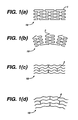
- Figures 1(a) and 1(b) are side views of a stent not in accordance with the present invention having circumferentially disposed bands wherein the stent is in axially unbent and bent positions respectively, the latter showing protruding edges;
- Figures 1(c) and 1(d) are side views of an axially flexible stent in accordance with the present invention wherein the stent is in unbent and bent positions respectively, the latter displaying an absence of protruding edges;
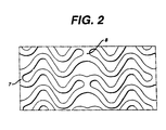
- Figure 2 is a side view of a portion of the stent of Figures 1(c) and 1(d) showing the longitudinal bands, spaces, and inner radial measurements of bends in the bands being measured in inches;
- Figures 3(a) and 3(b) show a portion of the stent of Figure 2 with two bands between two circumferential links (a) before expansion in the undeformed state; and (b) after expansion, in the deformed state;
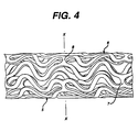
- Figure 4 is a view along the length of a piece of cylindrical stent (ends not shown) prior to expansion showing the exterior surface of the cylinder of the stent and the characteristic banding pattern;
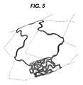
- Figure 5 is an isometric view of a deflection plot where the stent of Figure 2 is expanded to a larger diameter of 5mm;
- Figure 6 shows a two-dimensional layout of the stent of Figure 4 to form a cylinder such that edge "A" meets edge "B", and illustrating the spring-like action provided in circumferential and longitudinal directions;
- Figure 7 shows a two dimensional layout of the stent. The ends are modified such that the length (LA) is about 20% shorter than length (LB) and the width of the band A is greater than the width of band B;
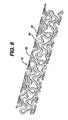
- Figure 8 shows a perspective view of a stent containing flexible connectors as described in the present invention;
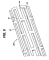
- Figure 9 is a perspective view of a stent not in accordance with the present invention;
- Figures 10a and 10b are plan views of a metal sheet which is formed into a stent not in accordance with the present invention; and
- Figures 11 and 12 are still other alternate embodiments not in accordance with the present invention.
-
- Improvements afforded by embodiments of the present invention include the following. First, there is an increased flexibility in two planes of the non-expanded stent while maintaining radial strength and a high percentage open area after expansion. Second, the stent of this invention provides even pressure on the expanding stent that ensures the consistent and continuous contact of expanded stent against artery wall. Third, the stent affords an avoidance of protruding parts during bending. Fourth, there is a removal of existing restrictions on maximum size of the stent. Fifth, the stent reduces any shortening effect during expansion of the stent.
- In a preferred embodiment of the invention, an expandable
cylindrical stent 10 is provided having a fenestrated structure for placement in a blood vessel, duct or lumen to hold the vessel, duct or lumen open, more particularly for protecting a segment of artery from restenosis after angioplasty. Thestent 10 may be expanded circumferentially and maintained in an expanded, circumferentially rigid configuration. Thestent 10 is axially flexible and when flexed at a band, thestent 10 avoids any externally protruding component parts. - Figure 1 shows what happens to a
stent 10, of a similar design to a preferred embodiment herein but utilizing instead a series of circumferentially disposed bands, when caused to bend in a manner that is likely encountered within a lumen of the body. Astent 10 with a circumferential arrangement of bands (1) experiences an effect analogous to a series of railroad cars on a track. As the row of railroad cars proceeds around the bend, the comer of each car proceeding around the bend after the coupling is caused to protrude from the contour of the track. Similarly, the serpentine circumferential bands have a series of protrusions (2) above the surface of thestent 10 as thestent 10 bends. - In contrast, the novel design of a preferred embodiment is shown in Figures 1(c) and 1(d) and Figure 7. There, the bands (3) are axially flexible and are arranged along the longitudinal axis, avoids such an effect when the
stent 10 is bent, so the bent bands (4) do not protrude from the profile of the curve of thestent 10. Further, any flaring at the ends of thestent 10 that might occur with astent 10 having a uniform structure is substantially eliminated by introducing a modification at the ends of thestent 10. This modification comprises decreasing the spatial frequency and increasing the width of the corresponding bands in a circumferential direction (LA and A) compared to that of the intermediate section. (IB and B). - In an embodiment of the invention, the spatial frequency LA may be decreased 0-50% with respect to LB, and the width A may be increased in the range of 0-150% with respect to B. Other modifications at the ends of the
stent 10 may include increasing the thickness of the wall of thestent 10 and selective electropolishing. These modifications protect the artery and any plaque from abrasion that may be caused by thestent 10 ends during insertion of thestent 10. The modification also may provide increased radio-opacity at the ends of thestent 10. Hence it may be possible to more accurately locate thestent 10 once it is in place in the body. - The embodiment as shown in Figures 2 and 6 has the unique advantage of possessing effective "springs" in both circumferential and longitudinal directions shown as items (5) and (6) respectively. These springs provide the
stent 10 with the flexibility necessary both to navigate vessels in the body with reduced friction and to expand at the selected site in a manner that provides the final necessary expanded dimensions without undue force while retaining structural resilience of the expanded structure. - As shown in both Figures 2, 4 and 6, each longitudinal band undulates through approximately two cycles before there is formed a circumferential link to an adjacent band. Prior to expansion, each waveform W associated with each of the bands will have approximately the same fundamental spatial frequency. The bands are so disposed that the wave W associated with them are spatially aligned, so as to be generally in phase with one another as shown in Figure 6.
- The aligned bands on the longitudinal axis are connected at a plurality of periodic locations, by a short circumferential link to an adjacent band. Consider a first common axial position such as shown by the line X-X in Figures 4 and 6. Here an adjacent pair of bands is joined by
circumferential link 7. Similarly other pairs of bands are also linked at this common axial position. At a second common axial position, shown in Figure 6 by the line Y-Y, an adjacent pair of bands is joined bycircumferential link 8. However, any given pair of bands that is linked at X-X is not linked at Y-Y and vice-versa. The X-X pattern of linkages repeats at the common axial position Z-Z. In general, there are thus two groups of common axial positions. In each of the axial positions of any one group are links between the same pairs of adjacent bands, and the groups alternate along the longitudinal axis of the embodiment. In this way,circumferential spring 6 and thelongitudinal spring 6 are provided. - A feature of the expansion event is that the pattern of open space in the
stent 10 of the embodiment of Figure 2 before expansion is different from the pattern of thestent 10 after expansion. In particular, in a preferred embodiment, the pattern of open space on thestent 10 before expansion is serpentine, whereas after expansion, the pattern approaches a diamond shape (3a, 3b). In embodiments of the invention, expansion may be achieved using pressure from an expanding balloon or by other mechanical means. - In the course of expansion, as shown in Figure 3, the wave W shaped bands tend to become straighter. When the bands become straighter, they become stiffer and thereby withstand relatively high radial forces. Figure 3 shows how radial expansion of the
stent 10 causes the openings (or "fenestrations") to open up into a diamond shape with maximum stress being expended on the apices of the diamond along the longitudinal axis. When finite element analyses including strain studies were performed on thestent 10, it was found that maximum strain was experienced on the bands and links and was below the maximum identified as necessary to maintain structural integrity. - The optimization of strain of the
stent 10 is achieved by creating as large a turn radius as possible in the wave W associated with each band in thenon-expanded stent 10. This is accomplished while preserving a sufficient number of bands and links to preserve the structural integrity of thestent 10 after expansion. In an embodiment of the invention, the strain may be less than 0.57 m/m (0.57 inches/inch) for 316L stainless steel. The expansion pressure may be 1.013 - 7.091 bar (1.0-7.0 atmospheres). The number of bands and the spatial frequency of the wave W on the longitudinal axis also affect the number of circumferential links. The circumferential links contribute structural integrity during application of radial force used in expansion of thestent 10 and in the maintenance of the expanded form. It is to be noted that the current invention is not limited to a single set of parameters. Nonetheless, an example of astent 10 of the invention having a longitudinal axis and providing axial flexibility as described above is shown in Figure 6. Thisstent 10 has an expanded diameter of 4mm and a length of 30mm. For example, it may have about 8-12 rows, more particularly 10 rows and about 6-10 slots, more particularly 8 slots (a slot is shown in Figure 6 as extending between X and Z). The stent may also have a wave W amplitude of about 1/4-1/10 of a slot length, more particularly 1/8 of a slot length. - The
stent 10 may be fabricated from many methods. For example, thestent 10 may be fabricated from a hollow or formed stainless steel tube that may be cut out using lasers, electric discharge milling (EDM), chemical etching or other means. Thestent 10 is inserted into the body and placed at the desired site in an unexpanded form. In a preferred embodiment, expansion of thestent 10 is effected in a blood vessel by means of a balloon catheter, where the final diameter of thestent 10 is a function of the diameter of the balloon catheter used. - In contrast to stents of the prior art, the
stent 10 of the invention can be made at any desired length, most preferably at a nominal 30mm length that can be extended or diminished by increments, for example 1.9mm increments. - It will be appreciated that a
stent 10 in accordance with the present invention may be embodied in a shape memory material, including, for example, an appropriate alloy of nickel and titanium; or stainless steel. In this embodiment after thestent 10 has been formed, it may be compressed so as to occupy a space sufficiently small as to permit its insertion in a blood vessel or other tissue by insertion means, wherein the insertion means include a suitable catheter, or flexible rod. On emerging from the catheter, thestent 10 may be configured to expand into the desired configuration where the expansion is automatic or triggered by a change in pressure, temperature or electrical stimulation. - An embodiment of the
improved stent 10 has utility not only within blood vessels as described above but also in any tubular system of the body such as the bile ducts, the urinary system, the digestive tube, and the tubes of the reproductive system in both men and women. - In yet a further embodiment there is described a
stent 10 as presently disclosed containing a multiplicity ofcurvilinear segments 20. Thesecurvilinear segments 20 are connected to each other via a generallyperpendicular connector 25. The generallyperpendicular connector 25 lies substantially in the plane perpendicular to the longitudinal axis of thestent 10. Each of thestent 10 segments as described herein is connected to anadjacent stent 10 segment. This is done using a series of flexible connectors. Importantly, the connectors themselves can be made narrower at their midpoints. This enhances the possibility of flexure at that point. Of course, it is to be realized that alternate designs of the connector to insure flexibility are possible, and contemplated by this invention. - In essence, therefore, the
stent 10 as described in Figure 8 is astent 10 of considerable flexibility when compared to more rigid rectilinear stents. Nonetheless, thestent 10 of the present invention does not depart from the basic concepts set forth herein, in that it discloses a continuously curvilinear strut. This curvilinear strut is connected to other curvilinear struts via a series of "second" (more flexible) connectors, as described above. - In any regard, it can be seen that the
stent 10 of the present invention incorporates various new and useful members. One of them is the flexible connector in conjunction with a generally curvilinear stent. Another is the use of the generally larger struts at the ends of thestent 10 in order to provide for continued support at thestent 10 ends. A final aspect is the use of flexible connectors amongststent 10 segments to provide for greater flexibility. - In all regards, however, it is to be seen that the present invention is to be determined from the attached claims and their equivalents.
- As seen in Figures 9-11, there is disclosed a novel method for manufacturing a stent which will have variable wall thicknesses. For instance, the
stents struts - As seen in Figures 10a and 10b, the stent initially starts out as a sheet S of metal. Then, the metal sheet S is rolled in the central region appearing between the two dotted lines to the specified wall thickness for the middle region of the stent. The rolling process produces a "texture" surface finish in the interior middle section of a stent. As seen in Figure 10b, the stent sheet now has two wall thicknesses T, T'. One thickness T is contained at the proximal end of the stent. One thickness T is contained at the distal end of the stent. These typically kept the same. However, as can be seen better in Figure 10b, the thickness T' in the middle of the stent is now narrower. It is perceived that this particular stent, when finally formed, will be more flexible in its middle sections, and more rigid in its distal and proximal ends. This may be desirable, for instance, where the stent is necessary to be "anchored" in the coronary artery or for ostial lesions. Thicker ends also allow for increased radioopacity at the ends.
- Of course, this present stent size presents particular advantage. The rolling process produces a textured surface in the interior middle section of the stent. This textured surface will adhere more readily to the walls of the artery. Because the stent is thereafter rolled, no electro-polishing is involved in the fabrication of the stent, saving costs to manufacture.
- As seen in Figures 9 and 11, the variable thickness of the stent can be made in a variety of locations. For instance in Figure 9, the
stent 200 has thicker ends than the middle section of the stent. But in Figure 11, thestent 300 has thinner bridges than the serpentine pattern contained in the sent. - In addition to rolling it is clearly conceivable that the present invention can be accomplished by other metal forming methods. For instance, the center of the stent can be stamped and the stent ends welded to one another. In addition, the stent can be electropolished to reduce the thickness of the center of the stent. Or, the stent is laser-etched in both the thickness and the width of the struts. What is important however, is the ability of the stent to be made more flexible.
- It may be desirable to describe a method for manufacturing the stent that is disclosed in Figures 9-11. This is done using a photochemical machine process. The stent would be photochemically machined from sheet material, 316L stainless steel in accordance with ASTM F 139. Tolerances of the sheet are kept within ± 5% of the sheet thickness. For a typical stent with a finished wall of 76.2 µm of (0.003 inch) this would translate into ±3.81µm (0.00015 inch). Surface finish is maintained as specified in ASTM A 480, No. 8. (This is defined as a "mirror" finish, and is at least as good currently manufactured stents.) Tensile strength will be in accordance with the annealed temper defined in Table 3 of ASTM F 139. This creates an ultimate tensile strength of at least 489.5 MN/m2(71,000 psi), a yield strength of at least (27,500 psi), and a percentage elongation of 50.8 µm (2 inch) - 40% min. Tolerances on the photochemically machined stent are kept within ± 10% of the material thickness. For a typical stent with a finished wall thickness of 76.2 µm (0.003 inch) this would translate to a strut/bridge tolerance of ±3.81 µm (0.0003 inch)
- Manufacturing takes place on a reel to reel machine. This would mean that the parts would be made from a single mask with identical dimensions on successive parts. The concept requires that the two sheet ends E, E', which are to be folded onto each other, are etched in such a way as to produce a joint with both tensile and shear components.
- The process described above helps the performance of stents in three ways:
- 1. The strength of the joint (at the brazing point) would be greatly enhanced.
- 2. The "notch" in the struts (as seen in Figure 9, for instance, and identified as N) would act as an alignment tool for lining up the ends to be brazed.
- 3. The increased surface area of the joint would insure that the joint, if brazed using a radiopaque alloy, would be visible with a fluoroscope.
-
- With regard to roll forming the tube to make the stent, the annealed tempering of the material as described herein easily converts to being formed into a tube. Automated equipment capturing both the inner and outer diameters of the tube will be able to repeatedly form the tube (and therefore, the stent) to the appropriate configuration.
- The brazing of the joint will be accomplished as follows. An alloy currently perceived to be useful is one consisting of 82% gold (Au) and 18% nickel (Ni). The alloy is controlled by Aerospace Material Specification (AMS) 4787. (It is known that the alloy is biocompatible.) The brazing cycle would involve temperatures currently being used to anneal stents under MIL-H-6875, Military specification heat treatent of steel. A review of MIL-STD-889, Military Standard, Dissimilar Metals allows that under desired conditions, the Au-Ni braze alloy will not create a galvanic couple with the 316L stainless steel. The quality controls governing the brazed joint are in accordance with MIL-B-7883. One of the other advantages of the gold brazing alloy is the creation of a "radio-opaque" marker on the stent during the joining operation. This marker provides an easier to see stent under fluoroscopy.
- Finally, the stent may be etched so as to have tapered walls. The typical walls are seen in cross section in Figure 12. This tapered wall allows the stent to be more flexible at one end as compared to the other.
- Of course, alternate embodiments of the invention are possible without departing from the scope hereof. What the invention described herein is to be derived from the appended claims and their equivalents.
Claims (11)
- A stent (10) comprising:characterised in that the struts comprise longitudinally disposed curvilinear struts (3), said strut thickness (T;T') being variable along the length of said struts.a generally tubular device with a diameter and a length having a pattern of interconnected struts (3), said struts having a cross-sectional width and thickness (T;T'); andsaid strut thickness being variable along the length of said stent;
- The stent of claim 1, wherein the variable strut thickness is varied along the length of the strut (3) so that said strut is thicker (1) at its ends than in the middle (T').
- The stent of claim 1, wherein said struts (3) are configured so that there are portions of relative thickness (T) and relative thinness (T') along the length of the stent (10), and said portions of relative thickness are interspersed between said portions of relative thinness.
- The stent of claim 1, wherein the variable strut thickness is varied along the length of the strut (3) so that said strut is relatively thicker at one of its ends than at the other.
- The stent (10) of any preceding claim, wherein said longitudinally disposed curvilinear struts (3) have a waveform (W) said stent (10) has first and second end regions with an intermediate section between the two, the spacial frequency(LA) of the waveform (W) in at least one of the end regions being decreased compared with that (LB) in the intermediate section.
- The stent of claim 5, wherein the spacial frequency (LA) in the at least one end region is decreased by 20% compared to the spacial frequency (LB) in the intermediate section.
- The stent of claim 5 or claim 6, wherein the struts (3) have a cross-sectional width and thickness, the width (A) being greater in the end regions than the width (B) in the intermediate section.
- The stent of any preceding claim, wherein said struts (3) are cut from said tubular device.
- The stent of any preceding claim wherein said struts (3) are generally parallel, and are connected to one another by circumferential links (7,8).
- The stent of claim 9, wherein the links are relatively narrower at their midpoints.
- The stent of any preceding claim, wherein the stent (10) is for use in combination with a balloon catheter.
Applications Claiming Priority (2)
| Application Number | Priority Date | Filing Date | Title |
|---|---|---|---|
| US288406 | 1999-04-08 | ||
| US09/288,406 US6325825B1 (en) | 1999-04-08 | 1999-04-08 | Stent with variable wall thickness |
Publications (2)
| Publication Number | Publication Date |
|---|---|
| EP1042997A1 EP1042997A1 (en) | 2000-10-11 |
| EP1042997B1 true EP1042997B1 (en) | 2005-03-02 |
Family
ID=23106964
Family Applications (1)
| Application Number | Title | Priority Date | Filing Date |
|---|---|---|---|
| EP00302937A Expired - Lifetime EP1042997B1 (en) | 1999-04-08 | 2000-04-07 | Stent with variable wall thickness |
Country Status (8)
| Country | Link |
|---|---|
| US (3) | US6325825B1 (en) |
| EP (1) | EP1042997B1 (en) |
| JP (1) | JP2000312721A (en) |
| AT (1) | ATE289782T1 (en) |
| AU (1) | AU768642B2 (en) |
| CA (1) | CA2304325C (en) |
| DE (1) | DE60018318T2 (en) |
| ES (1) | ES2235779T3 (en) |
Cited By (49)
| Publication number | Priority date | Publication date | Assignee | Title |
|---|---|---|---|---|
| US7789905B2 (en) | 1998-09-05 | 2010-09-07 | Abbottt Laboratories Vascular Enterprises Limited | Apparatus for a stent having an expandable web structure |
| US7811314B2 (en) | 1998-09-05 | 2010-10-12 | Abbott Laboratories Vascular Enterprises Limited | Methods and apparatus for stenting comprising enhanced embolic protection coupled with improved protections against restenosis and thrombus formation |
| US7815763B2 (en) | 2001-09-28 | 2010-10-19 | Abbott Laboratories Vascular Enterprises Limited | Porous membranes for medical implants and methods of manufacture |
| US7842083B2 (en) | 2001-08-20 | 2010-11-30 | Innovational Holdings, Llc. | Expandable medical device with improved spatial distribution |
| US7850726B2 (en) | 2007-12-20 | 2010-12-14 | Abbott Laboratories Vascular Enterprises Limited | Endoprosthesis having struts linked by foot extensions |
| US7887578B2 (en) | 1998-09-05 | 2011-02-15 | Abbott Laboratories Vascular Enterprises Limited | Stent having an expandable web structure |
| US7931683B2 (en) | 2007-07-27 | 2011-04-26 | Boston Scientific Scimed, Inc. | Articles having ceramic coated surfaces |
| US7938855B2 (en) | 2007-11-02 | 2011-05-10 | Boston Scientific Scimed, Inc. | Deformable underlayer for stent |
| US7942926B2 (en) | 2007-07-11 | 2011-05-17 | Boston Scientific Scimed, Inc. | Endoprosthesis coating |
| US7976915B2 (en) | 2007-05-23 | 2011-07-12 | Boston Scientific Scimed, Inc. | Endoprosthesis with select ceramic morphology |
| US7981150B2 (en) | 2006-11-09 | 2011-07-19 | Boston Scientific Scimed, Inc. | Endoprosthesis with coatings |
| US8002823B2 (en) | 2007-07-11 | 2011-08-23 | Boston Scientific Scimed, Inc. | Endoprosthesis coating |
| US8016874B2 (en) | 2007-05-23 | 2011-09-13 | Abbott Laboratories Vascular Enterprises Limited | Flexible stent with elevated scaffolding properties |
| US8029554B2 (en) | 2007-11-02 | 2011-10-04 | Boston Scientific Scimed, Inc. | Stent with embedded material |
| US8066763B2 (en) | 1998-04-11 | 2011-11-29 | Boston Scientific Scimed, Inc. | Drug-releasing stent with ceramic-containing layer |
| US8067054B2 (en) | 2007-04-05 | 2011-11-29 | Boston Scientific Scimed, Inc. | Stents with ceramic drug reservoir layer and methods of making and using the same |
| US8071156B2 (en) | 2009-03-04 | 2011-12-06 | Boston Scientific Scimed, Inc. | Endoprostheses |
| US8070797B2 (en) | 2007-03-01 | 2011-12-06 | Boston Scientific Scimed, Inc. | Medical device with a porous surface for delivery of a therapeutic agent |
| US8128679B2 (en) | 2007-05-23 | 2012-03-06 | Abbott Laboratories Vascular Enterprises Limited | Flexible stent with torque-absorbing connectors |
| US8187620B2 (en) | 2006-03-27 | 2012-05-29 | Boston Scientific Scimed, Inc. | Medical devices comprising a porous metal oxide or metal material and a polymer coating for delivering therapeutic agents |
| US8216632B2 (en) | 2007-11-02 | 2012-07-10 | Boston Scientific Scimed, Inc. | Endoprosthesis coating |
| US8221822B2 (en) | 2007-07-31 | 2012-07-17 | Boston Scientific Scimed, Inc. | Medical device coating by laser cladding |
| US8231980B2 (en) | 2008-12-03 | 2012-07-31 | Boston Scientific Scimed, Inc. | Medical implants including iridium oxide |
| US8230913B2 (en) | 2001-01-16 | 2012-07-31 | Halliburton Energy Services, Inc. | Expandable device for use in a well bore |
| US8287937B2 (en) | 2009-04-24 | 2012-10-16 | Boston Scientific Scimed, Inc. | Endoprosthese |
| US8337544B2 (en) | 2007-12-20 | 2012-12-25 | Abbott Laboratories Vascular Enterprises Limited | Endoprosthesis having flexible connectors |
| US8353949B2 (en) | 2006-09-14 | 2013-01-15 | Boston Scientific Scimed, Inc. | Medical devices with drug-eluting coating |
| US8431149B2 (en) | 2007-03-01 | 2013-04-30 | Boston Scientific Scimed, Inc. | Coated medical devices for abluminal drug delivery |
| US8449603B2 (en) | 2008-06-18 | 2013-05-28 | Boston Scientific Scimed, Inc. | Endoprosthesis coating |
| US8574615B2 (en) | 2006-03-24 | 2013-11-05 | Boston Scientific Scimed, Inc. | Medical devices having nanoporous coatings for controlled therapeutic agent delivery |
| US8771343B2 (en) | 2006-06-29 | 2014-07-08 | Boston Scientific Scimed, Inc. | Medical devices with selective titanium oxide coatings |
| USRE45011E1 (en) | 2000-10-20 | 2014-07-15 | Halliburton Energy Services, Inc. | Expandable tubing and method |
| US8815273B2 (en) | 2007-07-27 | 2014-08-26 | Boston Scientific Scimed, Inc. | Drug eluting medical devices having porous layers |
| US8815275B2 (en) | 2006-06-28 | 2014-08-26 | Boston Scientific Scimed, Inc. | Coatings for medical devices comprising a therapeutic agent and a metallic material |
| US8900292B2 (en) | 2007-08-03 | 2014-12-02 | Boston Scientific Scimed, Inc. | Coating for medical device having increased surface area |
| US8920491B2 (en) | 2008-04-22 | 2014-12-30 | Boston Scientific Scimed, Inc. | Medical devices having a coating of inorganic material |
| US8920488B2 (en) | 2007-12-20 | 2014-12-30 | Abbott Laboratories Vascular Enterprises Limited | Endoprosthesis having a stable architecture |
| US8932346B2 (en) | 2008-04-24 | 2015-01-13 | Boston Scientific Scimed, Inc. | Medical devices having inorganic particle layers |
| US9173977B2 (en) | 2010-04-19 | 2015-11-03 | Angioscore, Inc. | Coating formulations for scoring or cutting balloon catheters |
| US9179936B2 (en) | 2012-02-08 | 2015-11-10 | Quattro Vascular Pte Ltd. | Constraining structure with non-linear axial struts |
| US9199066B2 (en) | 2010-03-12 | 2015-12-01 | Quattro Vascular Pte Ltd. | Device and method for compartmental vessel treatment |
| US9216033B2 (en) | 2012-02-08 | 2015-12-22 | Quattro Vascular Pte Ltd. | System and method for treating biological vessels |
| US9284409B2 (en) | 2007-07-19 | 2016-03-15 | Boston Scientific Scimed, Inc. | Endoprosthesis having a non-fouling surface |
| US9351756B2 (en) | 2010-09-21 | 2016-05-31 | Angioscore, Inc. | Method and system for treating valve stenosis |
| US9375328B2 (en) | 2001-11-09 | 2016-06-28 | Angioscore, Inc. | Balloon catheter with non-deployable stent |
| US9586031B2 (en) | 2005-05-11 | 2017-03-07 | Angioscore, Inc. | Methods and systems for delivering substances into luminal walls |
| US9962529B2 (en) | 2003-01-21 | 2018-05-08 | Angioscore, Inc. | Apparatus and methods for treating hardened vascular lesions |
| US10086178B2 (en) | 2001-11-09 | 2018-10-02 | Angioscore, Inc. | Balloon catheter with non-deployable stent |
| US10117668B2 (en) | 2013-10-08 | 2018-11-06 | The Spectranetics Corporation | Balloon catheter with non-deployable stent having improved stability |
Families Citing this family (219)
| Publication number | Priority date | Publication date | Assignee | Title |
|---|---|---|---|---|
| US6309414B1 (en) * | 1997-11-04 | 2001-10-30 | Sorin Biomedica Cardio S.P.A. | Angioplasty stents |
| US6395019B2 (en) | 1998-02-09 | 2002-05-28 | Trivascular, Inc. | Endovascular graft |
| US6558415B2 (en) * | 1998-03-27 | 2003-05-06 | Intratherapeutics, Inc. | Stent |
| US6132461A (en) * | 1998-03-27 | 2000-10-17 | Intratherapeutics, Inc. | Stent with dual support structure |
| DE19839646A1 (en) * | 1998-08-31 | 2000-03-09 | Jomed Implantate Gmbh | Stent |
| DE19840645A1 (en) | 1998-09-05 | 2000-03-09 | Jomed Implantate Gmbh | Stent |
| US20020019660A1 (en) * | 1998-09-05 | 2002-02-14 | Marc Gianotti | Methods and apparatus for a curved stent |
| WO2002064061A2 (en) * | 1998-09-05 | 2002-08-22 | Jomed Gmbh | Stent having a web structure and suitable for forming a curved stent |
| US6709465B2 (en) * | 1999-03-18 | 2004-03-23 | Fossa Medical, Inc. | Radially expanding ureteral device |
| US7175644B2 (en) * | 2001-02-14 | 2007-02-13 | Broncus Technologies, Inc. | Devices and methods for maintaining collateral channels in tissue |
| US6254631B1 (en) | 1999-09-23 | 2001-07-03 | Intratherapeutics, Inc. | Stent with enhanced friction |
| US7226475B2 (en) | 1999-11-09 | 2007-06-05 | Boston Scientific Scimed, Inc. | Stent with variable properties |
| US8632583B2 (en) | 2011-05-09 | 2014-01-21 | Palmaz Scientific, Inc. | Implantable medical device having enhanced endothelial migration features and methods of making the same |
| US6572646B1 (en) * | 2000-06-02 | 2003-06-03 | Advanced Cardiovascular Systems, Inc. | Curved nitinol stent for extremely tortuous anatomy |
| US6547818B1 (en) * | 2000-10-20 | 2003-04-15 | Endotex Interventional Systems, Inc. | Selectively thinned coiled-sheet stents and methods for making them |
| US20010044650A1 (en) * | 2001-01-12 | 2001-11-22 | Simso Eric J. | Stent for in-stent restenosis |
| DE60226185D1 (en) * | 2001-01-16 | 2008-06-05 | Schlumberger Technology Bv | Bistable, expandable device and method for expanding such a device |
| AU2006202182B2 (en) * | 2001-01-16 | 2010-03-25 | Halliburton Energy Services, Inc. | Expandable devices |
| US6790227B2 (en) | 2001-03-01 | 2004-09-14 | Cordis Corporation | Flexible stent |
| US6679911B2 (en) * | 2001-03-01 | 2004-01-20 | Cordis Corporation | Flexible stent |
| US6733521B2 (en) | 2001-04-11 | 2004-05-11 | Trivascular, Inc. | Delivery system and method for endovascular graft |
| US6761733B2 (en) | 2001-04-11 | 2004-07-13 | Trivascular, Inc. | Delivery system and method for bifurcated endovascular graft |
| US6673106B2 (en) | 2001-06-14 | 2004-01-06 | Cordis Neurovascular, Inc. | Intravascular stent device |
| US6818013B2 (en) | 2001-06-14 | 2004-11-16 | Cordis Corporation | Intravascular stent device |
| AU2002345328A1 (en) | 2001-06-27 | 2003-03-03 | Remon Medical Technologies Ltd. | Method and device for electrochemical formation of therapeutic species in vivo |
| US6605110B2 (en) | 2001-06-29 | 2003-08-12 | Advanced Cardiovascular Systems, Inc. | Stent with enhanced bendability and flexibility |
| JP2003062084A (en) * | 2001-08-27 | 2003-03-04 | Nipro Corp | Stent with improved flexibility |
| US7708712B2 (en) | 2001-09-04 | 2010-05-04 | Broncus Technologies, Inc. | Methods and devices for maintaining patency of surgically created channels in a body organ |
| US7252679B2 (en) * | 2001-09-13 | 2007-08-07 | Cordis Corporation | Stent with angulated struts |
| EP1917931A3 (en) | 2001-12-03 | 2013-02-27 | Intek Technology LLC | Multi-segment modular stent and methods for manufacturing stents |
| US20030176914A1 (en) * | 2003-01-21 | 2003-09-18 | Rabkin Dmitry J. | Multi-segment modular stent and methods for manufacturing stents |
| US20100016943A1 (en) | 2001-12-20 | 2010-01-21 | Trivascular2, Inc. | Method of delivering advanced endovascular graft |
| WO2003053288A1 (en) * | 2001-12-20 | 2003-07-03 | Trivascular, Inc. | Advanced endovascular graft |
| US7147661B2 (en) | 2001-12-20 | 2006-12-12 | Boston Scientific Santa Rosa Corp. | Radially expandable stent |
| US7445629B2 (en) * | 2002-01-31 | 2008-11-04 | Boston Scientific Scimed, Inc. | Medical device for delivering biologically active material |
| US7326245B2 (en) * | 2002-01-31 | 2008-02-05 | Boston Scientific Scimed, Inc. | Medical device for delivering biologically active material |
| EP1507494A2 (en) * | 2002-05-06 | 2005-02-23 | Abbott Laboratories | Endoprosthesis for controlled contraction and expansion |
| EP2529707B1 (en) * | 2002-05-08 | 2015-04-15 | Abbott Laboratories | Endoprosthesis having foot extensions |
| US7195648B2 (en) | 2002-05-16 | 2007-03-27 | Cordis Neurovascular, Inc. | Intravascular stent device |
| US6656220B1 (en) | 2002-06-17 | 2003-12-02 | Advanced Cardiovascular Systems, Inc. | Intravascular stent |
| US7086476B2 (en) | 2002-08-06 | 2006-08-08 | Schlumberger Technology Corporation | Expandable devices and method |
| US20040054398A1 (en) * | 2002-09-13 | 2004-03-18 | Cully Edward H. | Stent device with multiple helix construction |
| US8679517B2 (en) | 2002-09-26 | 2014-03-25 | Palmaz Scientific, Inc. | Implantable materials having engineered surfaces made by vacuum deposition and method of making same |
| JP2006505307A (en) | 2002-09-26 | 2006-02-16 | アドヴァンスド バイオ プロスセティック サーフェシーズ リミテッド | Implantable material with designed surface and method of making the material |
| US8268340B2 (en) | 2002-09-26 | 2012-09-18 | Advanced Bio Prosthetic Surfaces, Ltd. | Implantable materials having engineered surfaces and method of making same |
| US7959671B2 (en) | 2002-11-05 | 2011-06-14 | Merit Medical Systems, Inc. | Differential covering and coating methods |
| US7637942B2 (en) | 2002-11-05 | 2009-12-29 | Merit Medical Systems, Inc. | Coated stent with geometry determinated functionality and method of making the same |
| US7875068B2 (en) | 2002-11-05 | 2011-01-25 | Merit Medical Systems, Inc. | Removable biliary stent |
| AU2002356575B2 (en) * | 2002-11-08 | 2009-07-16 | Jean-Claude Laborde | Endoprosthesis for vascular bifurcation |
| US8282678B2 (en) * | 2002-11-13 | 2012-10-09 | Allium Medical Solutions Ltd. | Endoluminal lining |
| US20040102831A1 (en) * | 2002-11-22 | 2004-05-27 | Murray Robert J. | Stent having tapered edges |
| US8105373B2 (en) | 2002-12-16 | 2012-01-31 | Boston Scientific Scimed, Inc. | Flexible stent with improved axial strength |
| US6849084B2 (en) * | 2002-12-31 | 2005-02-01 | Intek Technology L.L.C. | Stent delivery system |
| US6916409B1 (en) | 2002-12-31 | 2005-07-12 | Advanced Cardiovascular Systems, Inc. | Apparatus and process for electrolytic removal of material from a medical device |
| WO2004067199A1 (en) * | 2003-01-27 | 2004-08-12 | Graphion Technologies Usa, Llc | The method of cutting a ultrafine pipe or bar, and ultrafine pipe or bar cutted by it |
| GB0306176D0 (en) | 2003-03-18 | 2003-04-23 | Imp College Innovations Ltd | Tubing |
| EP1605867B1 (en) | 2003-03-18 | 2009-10-21 | Veryan Medical Limited | Helical stent |
| CN100558320C (en) | 2003-03-19 | 2009-11-11 | 先进生物假体表面有限公司 | Intracavity stent with intercolumniation interconnecting members |
| US20050131523A1 (en) * | 2003-04-02 | 2005-06-16 | Mehran Bashiri | Detachable and retrievable stent assembly |
| US7625401B2 (en) * | 2003-05-06 | 2009-12-01 | Abbott Laboratories | Endoprosthesis having foot extensions |
| US7625398B2 (en) * | 2003-05-06 | 2009-12-01 | Abbott Laboratories | Endoprosthesis having foot extensions |
| DE602004024053D1 (en) * | 2003-05-07 | 2009-12-24 | Advanced Bio Prothestic Surfac | METALLIC IMPLANTABLE PROSTHESIS AND MANUFACTURING METHOD THEREFOR |
| US20040230290A1 (en) * | 2003-05-15 | 2004-11-18 | Jan Weber | Medical devices and methods of making the same |
| US8308682B2 (en) | 2003-07-18 | 2012-11-13 | Broncus Medical Inc. | Devices for maintaining patency of surgically created channels in tissue |
| US20050060025A1 (en) * | 2003-09-12 | 2005-03-17 | Mackiewicz David A. | Radiopaque markers for medical devices |
| DE10342759A1 (en) * | 2003-09-16 | 2005-04-14 | Campus Gmbh & Co. Kg | Stent with improved durability |
| US20050159805A1 (en) * | 2004-01-20 | 2005-07-21 | Jan Weber | Functional coatings and designs for medical implants |
| US7803178B2 (en) * | 2004-01-30 | 2010-09-28 | Trivascular, Inc. | Inflatable porous implants and methods for drug delivery |
| US20050182474A1 (en) * | 2004-02-13 | 2005-08-18 | Medtronic Vascular, Inc. | Coated stent having protruding crowns and elongated struts |
| EP1753367A4 (en) * | 2004-03-11 | 2011-10-12 | Trivascular Inc | Modular endovascular graft |
| JP2007535342A (en) | 2004-03-11 | 2007-12-06 | パーキュテイニアス カルディオバスキュラー ソリューションズ ピー・ティー・ワイ リミテッド | Percutaneous prosthetic heart valve |
| DE102004012837B4 (en) * | 2004-03-16 | 2006-09-14 | Admedes Schuessler Gmbh | Stent having a web structure and method of making the same |
| US8858616B2 (en) | 2004-03-16 | 2014-10-14 | Admedes Schuessler Gmbh | Stent having a bridge structure |
| WO2005122953A2 (en) * | 2004-05-11 | 2005-12-29 | Oregon Health And Science University | Interfacial stent and method of maintaining patency of surgical fenestrations |
| US7993387B2 (en) * | 2004-05-14 | 2011-08-09 | Boston Scientific Scimed, Inc. | Stent with reduced weld profiles and a closed-end wire configuration |
| US7763064B2 (en) * | 2004-06-08 | 2010-07-27 | Medinol, Ltd. | Stent having struts with reverse direction curvature |
| US8999364B2 (en) | 2004-06-15 | 2015-04-07 | Nanyang Technological University | Implantable article, method of forming same and method for reducing thrombogenicity |
| US8409167B2 (en) | 2004-07-19 | 2013-04-02 | Broncus Medical Inc | Devices for delivering substances through an extra-anatomic opening created in an airway |
| EP1789107B1 (en) | 2004-08-30 | 2009-05-27 | Interstitial Therapeutics | Medical stent provided with inhibitors of atp synthesis |
| US7887579B2 (en) | 2004-09-29 | 2011-02-15 | Merit Medical Systems, Inc. | Active stent |
| DE102005016103B4 (en) * | 2005-04-08 | 2014-10-09 | Merit Medical Systems, Inc. | Duodenumstent |
| US8628565B2 (en) | 2005-04-13 | 2014-01-14 | Abbott Cardiovascular Systems Inc. | Intravascular stent |
| DE102005019649A1 (en) * | 2005-04-26 | 2006-11-02 | Alveolus Inc. | Flexible stent for positioning in lumen of esophagus comprises tube and stabilization members defined circumferentially about tube, where each member extends inwardly in tube to define inner diameter that is less than inner diameter of tube |
| US20060248698A1 (en) * | 2005-05-05 | 2006-11-09 | Hanson Brian J | Tubular stent and methods of making the same |
| US7731654B2 (en) | 2005-05-13 | 2010-06-08 | Merit Medical Systems, Inc. | Delivery device with viewing window and associated method |
| US8480728B2 (en) * | 2005-05-26 | 2013-07-09 | Boston Scientific Scimed, Inc. | Stent side branch deployment initiation geometry |
| US8273117B2 (en) * | 2005-06-22 | 2012-09-25 | Integran Technologies Inc. | Low texture, quasi-isotropic metallic stent |
| EP2364676B1 (en) | 2005-06-30 | 2018-12-19 | Abbott Laboratories | Endoprosthesis having foot extensions |
| US7637939B2 (en) * | 2005-06-30 | 2009-12-29 | Boston Scientific Scimed, Inc. | Hybrid stent |
| US20070038176A1 (en) * | 2005-07-05 | 2007-02-15 | Jan Weber | Medical devices with machined layers for controlled communications with underlying regions |
| US8043366B2 (en) | 2005-09-08 | 2011-10-25 | Boston Scientific Scimed, Inc. | Overlapping stent |
| US7647687B2 (en) * | 2005-09-14 | 2010-01-19 | Boston Scientific Scimed, Inc. | Method of manufacturing a stent |
| AU2006315812B2 (en) | 2005-11-10 | 2013-03-28 | Cardiaq Valve Technologies, Inc. | Balloon-expandable, self-expanding, vascular prosthesis connecting stent |
| US8840660B2 (en) | 2006-01-05 | 2014-09-23 | Boston Scientific Scimed, Inc. | Bioerodible endoprostheses and methods of making the same |
| US8089029B2 (en) | 2006-02-01 | 2012-01-03 | Boston Scientific Scimed, Inc. | Bioabsorbable metal medical device and method of manufacture |
| US8048150B2 (en) | 2006-04-12 | 2011-11-01 | Boston Scientific Scimed, Inc. | Endoprosthesis having a fiber meshwork disposed thereon |
| US20070264303A1 (en) * | 2006-05-12 | 2007-11-15 | Liliana Atanasoska | Coating for medical devices comprising an inorganic or ceramic oxide and a therapeutic agent |
| GB0609841D0 (en) | 2006-05-17 | 2006-06-28 | Angiomed Ag | Bend-capable tubular prosthesis |
| AU2007258592B2 (en) | 2006-06-06 | 2012-10-25 | Cook Incorporated | Stent with a crush-resistant zone |
| US8240020B2 (en) * | 2006-06-30 | 2012-08-14 | Advanced Cardiovascular Systems, Inc. | Stent retention mold and method |
| US10004584B2 (en) | 2006-07-10 | 2018-06-26 | First Quality Hygienic, Inc. | Resilient intravaginal device |
| US8613698B2 (en) | 2006-07-10 | 2013-12-24 | Mcneil-Ppc, Inc. | Resilient device |
| US10219884B2 (en) | 2006-07-10 | 2019-03-05 | First Quality Hygienic, Inc. | Resilient device |
| US8047980B2 (en) | 2006-07-10 | 2011-11-01 | Mcneil-Ppc, Inc. | Method of treating urinary incontinence |
| AU2007272601B2 (en) | 2006-07-10 | 2014-01-16 | First Quality Hygienic, Inc. | Resilient device |
| US7651523B2 (en) * | 2006-07-24 | 2010-01-26 | Cook Incorporated | Intraluminal device with flexible regions |
| EP2054537A2 (en) | 2006-08-02 | 2009-05-06 | Boston Scientific Scimed, Inc. | Endoprosthesis with three-dimensional disintegration control |
| WO2008034031A2 (en) | 2006-09-15 | 2008-03-20 | Boston Scientific Limited | Bioerodible endoprostheses and methods of making the same |
| CA2663220A1 (en) | 2006-09-15 | 2008-03-20 | Boston Scientific Limited | Medical devices and methods of making the same |
| JP2010503494A (en) | 2006-09-15 | 2010-02-04 | ボストン サイエンティフィック リミテッド | Biodegradable endoprosthesis and method for producing the same |
| WO2008034048A2 (en) | 2006-09-15 | 2008-03-20 | Boston Scientific Limited | Bioerodible endoprosthesis with biostable inorganic layers |
| EP2068962B1 (en) | 2006-09-18 | 2013-01-30 | Boston Scientific Limited | Endoprostheses |
| GB0622465D0 (en) * | 2006-11-10 | 2006-12-20 | Angiomed Ag | Stent |
| US20080140179A1 (en) * | 2006-12-12 | 2008-06-12 | Ladisa John F | Apparatus and method for minimizing flow disturbances in a stented region of a lumen |
| ES2506144T3 (en) | 2006-12-28 | 2014-10-13 | Boston Scientific Limited | Bioerodible endoprosthesis and their manufacturing procedure |
| US8623070B2 (en) | 2007-03-08 | 2014-01-07 | Thomas O. Bales | Tapered helical stent and method for manufacturing the stent |
| US8974514B2 (en) | 2007-03-13 | 2015-03-10 | Abbott Cardiovascular Systems Inc. | Intravascular stent with integrated link and ring strut |
| US7988723B2 (en) | 2007-08-02 | 2011-08-02 | Flexible Stenting Solutions, Inc. | Flexible stent |
| US8052745B2 (en) | 2007-09-13 | 2011-11-08 | Boston Scientific Scimed, Inc. | Endoprosthesis |
| US20090076591A1 (en) * | 2007-09-19 | 2009-03-19 | Boston Scientific Scimed, Inc. | Stent Design Allowing Extended Release of Drug and/or Enhanced Adhesion of Polymer to OD Surface |
| US8226701B2 (en) | 2007-09-26 | 2012-07-24 | Trivascular, Inc. | Stent and delivery system for deployment thereof |
| US8663309B2 (en) | 2007-09-26 | 2014-03-04 | Trivascular, Inc. | Asymmetric stent apparatus and method |
| US8066755B2 (en) | 2007-09-26 | 2011-11-29 | Trivascular, Inc. | System and method of pivoted stent deployment |
| AU2008308474B2 (en) | 2007-10-04 | 2014-07-24 | Trivascular, Inc. | Modular vascular graft for low profile percutaneous delivery |
| US20090118813A1 (en) * | 2007-11-02 | 2009-05-07 | Torsten Scheuermann | Nano-patterned implant surfaces |
| US8083789B2 (en) | 2007-11-16 | 2011-12-27 | Trivascular, Inc. | Securement assembly and method for expandable endovascular device |
| US8328861B2 (en) | 2007-11-16 | 2012-12-11 | Trivascular, Inc. | Delivery system and method for bifurcated graft |
| US7833266B2 (en) | 2007-11-28 | 2010-11-16 | Boston Scientific Scimed, Inc. | Bifurcated stent with drug wells for specific ostial, carina, and side branch treatment |
| US20090198321A1 (en) * | 2008-02-01 | 2009-08-06 | Boston Scientific Scimed, Inc. | Drug-Coated Medical Devices for Differential Drug Release |
| US20090198184A1 (en) * | 2008-02-05 | 2009-08-06 | Martin David C | Percutaneous biomedical devices with regenerative materials interface |
| US7998192B2 (en) | 2008-05-09 | 2011-08-16 | Boston Scientific Scimed, Inc. | Endoprostheses |
| US8236046B2 (en) | 2008-06-10 | 2012-08-07 | Boston Scientific Scimed, Inc. | Bioerodible endoprosthesis |
| US10898620B2 (en) | 2008-06-20 | 2021-01-26 | Razmodics Llc | Composite stent having multi-axial flexibility and method of manufacture thereof |
| US8206635B2 (en) | 2008-06-20 | 2012-06-26 | Amaranth Medical Pte. | Stent fabrication via tubular casting processes |
| US8206636B2 (en) | 2008-06-20 | 2012-06-26 | Amaranth Medical Pte. | Stent fabrication via tubular casting processes |
| US7951193B2 (en) | 2008-07-23 | 2011-05-31 | Boston Scientific Scimed, Inc. | Drug-eluting stent |
| US7985252B2 (en) | 2008-07-30 | 2011-07-26 | Boston Scientific Scimed, Inc. | Bioerodible endoprosthesis |
| CA2749026C (en) | 2008-09-29 | 2018-01-09 | Impala, Inc. | Heart valve |
| EP2845569A1 (en) | 2008-10-01 | 2015-03-11 | Cardiaq Valve Technologies, Inc. | Delivery system for vascular implant |
| US8382824B2 (en) | 2008-10-03 | 2013-02-26 | Boston Scientific Scimed, Inc. | Medical implant having NANO-crystal grains with barrier layers of metal nitrides or fluorides |
| US9149376B2 (en) | 2008-10-06 | 2015-10-06 | Cordis Corporation | Reconstrainable stent delivery system |
| US9597214B2 (en) | 2008-10-10 | 2017-03-21 | Kevin Heraty | Medical device |
| WO2010101901A2 (en) | 2009-03-02 | 2010-09-10 | Boston Scientific Scimed, Inc. | Self-buffering medical implants |
| WO2010121076A2 (en) | 2009-04-15 | 2010-10-21 | Cardiaq Valve Technologies, Inc. | Vascular implant and delivery system |
| US8221489B2 (en) * | 2009-08-20 | 2012-07-17 | Stentys | Device and method for treating a body lumen |
| US9730790B2 (en) | 2009-09-29 | 2017-08-15 | Edwards Lifesciences Cardiaq Llc | Replacement valve and method |
| US8668732B2 (en) | 2010-03-23 | 2014-03-11 | Boston Scientific Scimed, Inc. | Surface treated bioerodible metal endoprostheses |
| US8579964B2 (en) | 2010-05-05 | 2013-11-12 | Neovasc Inc. | Transcatheter mitral valve prosthesis |
| US9402754B2 (en) * | 2010-05-18 | 2016-08-02 | Abbott Cardiovascular Systems, Inc. | Expandable endoprostheses, systems, and methods for treating a bifurcated lumen |
| CA2803149C (en) | 2010-06-21 | 2018-08-14 | Impala, Inc. | Replacement heart valve |
| EP2618784B1 (en) | 2010-09-23 | 2016-05-25 | Edwards Lifesciences CardiAQ LLC | Replacement heart valves and delivery devices |
| EP2658484A1 (en) | 2010-12-30 | 2013-11-06 | Boston Scientific Scimed, Inc. | Multi stage opening stent designs |
| JP2014511247A (en) | 2011-03-03 | 2014-05-15 | ボストン サイエンティフィック サイムド,インコーポレイテッド | Low strain high strength stent |
| WO2012119037A1 (en) | 2011-03-03 | 2012-09-07 | Boston Scientific Scimed, Inc. | Stent with reduced profile |
| US9308087B2 (en) | 2011-04-28 | 2016-04-12 | Neovasc Tiara Inc. | Sequentially deployed transcatheter mitral valve prosthesis |
| US9554897B2 (en) | 2011-04-28 | 2017-01-31 | Neovasc Tiara Inc. | Methods and apparatus for engaging a valve prosthesis with tissue |
| US8728563B2 (en) | 2011-05-03 | 2014-05-20 | Palmaz Scientific, Inc. | Endoluminal implantable surfaces, stents, and grafts and method of making same |
| US8709034B2 (en) | 2011-05-13 | 2014-04-29 | Broncus Medical Inc. | Methods and devices for diagnosing, monitoring, or treating medical conditions through an opening through an airway wall |
| US9345532B2 (en) | 2011-05-13 | 2016-05-24 | Broncus Medical Inc. | Methods and devices for ablation of tissue |
| US20130085564A1 (en) * | 2011-10-03 | 2013-04-04 | Abbott Cardiovascular Systems Inc. | Modified scaffolds for peripheral applications |
| US9320623B2 (en) | 2011-10-04 | 2016-04-26 | Cook Medical Technologies Llc | Reduced wire profile stent |
| WO2013078235A1 (en) | 2011-11-23 | 2013-05-30 | Broncus Medical Inc | Methods and devices for diagnosing, monitoring, or treating medical conditions through an opening through an airway wall |
| EP2788067B1 (en) * | 2011-12-05 | 2017-08-09 | Stryker Corporation | Reinforced elongate medical device and method of manufacture |
| WO2013114201A1 (en) | 2012-02-01 | 2013-08-08 | Tanhum Feld | Device for compartmental dilatation of blood vessels |
| US8992595B2 (en) | 2012-04-04 | 2015-03-31 | Trivascular, Inc. | Durable stent graft with tapered struts and stable delivery methods and devices |
| US9498363B2 (en) | 2012-04-06 | 2016-11-22 | Trivascular, Inc. | Delivery catheter for endovascular device |
| NZ701992A (en) | 2012-05-14 | 2016-03-31 | Bard Inc C R | Uniformly expandable stent |
| US9345573B2 (en) | 2012-05-30 | 2016-05-24 | Neovasc Tiara Inc. | Methods and apparatus for loading a prosthesis onto a delivery system |
| US20140052272A1 (en) * | 2012-08-20 | 2014-02-20 | Boston Scientific Scimed, Inc. | Comfort stents |
| US20140200647A1 (en) * | 2013-01-14 | 2014-07-17 | Abbott Cardiovascular Systems Inc. | Stent with enhanced profile |
| US10583002B2 (en) | 2013-03-11 | 2020-03-10 | Neovasc Tiara Inc. | Prosthetic valve with anti-pivoting mechanism |
| US9610179B2 (en) | 2013-03-12 | 2017-04-04 | Cook Medical Technologies Llc | Atraumatic stent crowns |
| USD723165S1 (en) | 2013-03-12 | 2015-02-24 | C. R. Bard, Inc. | Stent |
| US9681951B2 (en) | 2013-03-14 | 2017-06-20 | Edwards Lifesciences Cardiaq Llc | Prosthesis with outer skirt and anchors |
| US20140277427A1 (en) | 2013-03-14 | 2014-09-18 | Cardiaq Valve Technologies, Inc. | Prosthesis for atraumatically grasping intralumenal tissue and methods of delivery |
| US9730791B2 (en) | 2013-03-14 | 2017-08-15 | Edwards Lifesciences Cardiaq Llc | Prosthesis for atraumatically grasping intralumenal tissue and methods of delivery |
| US9908635B2 (en) | 2013-03-15 | 2018-03-06 | Rolls-Royce North American Technologies Inc. | Aircraft system |
| US9572665B2 (en) | 2013-04-04 | 2017-02-21 | Neovasc Tiara Inc. | Methods and apparatus for delivering a prosthetic valve to a beating heart |
| US9320628B2 (en) * | 2013-09-09 | 2016-04-26 | Boston Scientific Scimed, Inc. | Endoprosthesis devices including biostable and bioabsorable regions |
| EP3583925B1 (en) * | 2013-12-24 | 2021-01-20 | Nipro Corporation | Stent |
| US10004599B2 (en) | 2014-02-21 | 2018-06-26 | Edwards Lifesciences Cardiaq Llc | Prosthesis, delivery device and methods of use |
| USD755384S1 (en) | 2014-03-05 | 2016-05-03 | Edwards Lifesciences Cardiaq Llc | Stent |
| CA2948379C (en) | 2014-05-19 | 2022-08-09 | J. Brent Ratz | Replacement mitral valve with annular flap |
| CN107155299A (en) * | 2014-06-02 | 2017-09-12 | 阿玛安斯医药私人公司 | Bioabsorbable support |
| US9730819B2 (en) * | 2014-08-15 | 2017-08-15 | Elixir Medical Corporation | Biodegradable endoprostheses and methods of their fabrication |
| US9855156B2 (en) | 2014-08-15 | 2018-01-02 | Elixir Medical Corporation | Biodegradable endoprostheses and methods of their fabrication |
| US10232148B2 (en) | 2014-11-17 | 2019-03-19 | TriReme Medical, LLC | Balloon catheter system and method of using same |
| US10307273B2 (en) | 2015-03-03 | 2019-06-04 | Boston Scientific Scimed, Inc. | Stent with anti-migration features |
| US10441416B2 (en) | 2015-04-21 | 2019-10-15 | Edwards Lifesciences Corporation | Percutaneous mitral valve replacement device |
| US10376363B2 (en) | 2015-04-30 | 2019-08-13 | Edwards Lifesciences Cardiaq Llc | Replacement mitral valve, delivery system for replacement mitral valve and methods of use |
| WO2016209970A1 (en) | 2015-06-22 | 2016-12-29 | Edwards Lifescience Cardiaq Llc | Actively controllable heart valve implant and methods of controlling same |
| US10092400B2 (en) | 2015-06-23 | 2018-10-09 | Edwards Lifesciences Cardiaq Llc | Systems and methods for anchoring and sealing a prosthetic heart valve |
| US10327924B2 (en) * | 2015-07-19 | 2019-06-25 | Sanford Health | Bridging stent graft with combination balloon expandable and self-expandable stents and methods for use |
| US10117744B2 (en) | 2015-08-26 | 2018-11-06 | Edwards Lifesciences Cardiaq Llc | Replacement heart valves and methods of delivery |
| US10575951B2 (en) | 2015-08-26 | 2020-03-03 | Edwards Lifesciences Cardiaq Llc | Delivery device and methods of use for transapical delivery of replacement mitral valve |
| US10350066B2 (en) | 2015-08-28 | 2019-07-16 | Edwards Lifesciences Cardiaq Llc | Steerable delivery system for replacement mitral valve and methods of use |
| EP3435930B1 (en) | 2016-03-31 | 2022-11-30 | Vesper Medical, Inc. | Intravascular implants |
| USD815744S1 (en) | 2016-04-28 | 2018-04-17 | Edwards Lifesciences Cardiaq Llc | Valve frame for a delivery system |
| EP3457985B1 (en) | 2016-05-16 | 2021-02-17 | Elixir Medical Corporation | Uncaging stent |
| US11622872B2 (en) | 2016-05-16 | 2023-04-11 | Elixir Medical Corporation | Uncaging stent |
| US10350062B2 (en) | 2016-07-21 | 2019-07-16 | Edwards Lifesciences Corporation | Replacement heart valve prosthesis |
| EP3500214A4 (en) | 2016-08-19 | 2019-07-24 | Edwards Lifesciences Corporation | Steerable delivery system for replacement mitral valve and methods of use |
| WO2018039631A1 (en) | 2016-08-26 | 2018-03-01 | Edwards Lifesciences Corporation | Multi-portion replacement heat valve prosthesis |
| US10758348B2 (en) | 2016-11-02 | 2020-09-01 | Edwards Lifesciences Corporation | Supra and sub-annular mitral valve delivery system |
| US10195027B2 (en) | 2016-11-04 | 2019-02-05 | Highlife Sas | Transcatheter valve prosthesis |
| US9999502B2 (en) | 2016-11-04 | 2018-06-19 | Highlife Sas | Transcather valve prosthesis |
| US11376121B2 (en) | 2016-11-04 | 2022-07-05 | Highlife Sas | Transcatheter valve prosthesis |
| US10456247B2 (en) | 2016-11-04 | 2019-10-29 | Highlife Sas | Transcatheter valve prosthesis |
| US10188514B2 (en) | 2016-11-04 | 2019-01-29 | Highlife Sas | Transcatheter valve prosthesis |
| US10813757B2 (en) | 2017-07-06 | 2020-10-27 | Edwards Lifesciences Corporation | Steerable rail delivery system |
| US10849769B2 (en) | 2017-08-23 | 2020-12-01 | Vesper Medical, Inc. | Non-foreshortening stent |
| US10271977B2 (en) | 2017-09-08 | 2019-04-30 | Vesper Medical, Inc. | Hybrid stent |
| US11357650B2 (en) | 2019-02-28 | 2022-06-14 | Vesper Medical, Inc. | Hybrid stent |
| US11628076B2 (en) | 2017-09-08 | 2023-04-18 | Vesper Medical, Inc. | Hybrid stent |
| WO2019147846A2 (en) | 2018-01-25 | 2019-08-01 | Edwards Lifesciences Corporation | Delivery system for aided replacement valve recapture and repositioning post- deployment |
| US11364134B2 (en) * | 2018-02-15 | 2022-06-21 | Vesper Medical, Inc. | Tapering stent |
| US11051934B2 (en) | 2018-02-28 | 2021-07-06 | Edwards Lifesciences Corporation | Prosthetic mitral valve with improved anchors and seal |
| US10500078B2 (en) | 2018-03-09 | 2019-12-10 | Vesper Medical, Inc. | Implantable stent |
| CN112826633B (en) * | 2020-12-31 | 2024-03-19 | 中国人民解放军总医院第一医学中心 | Anti-displacement intravascular tectorial membrane bracket |
Family Cites Families (53)
| Publication number | Priority date | Publication date | Assignee | Title |
|---|---|---|---|---|
| US544498A (en) * | 1895-08-13 | Mine trap-door | ||
| US367744A (en) * | 1887-08-02 | Bellows | ||
| US3488988A (en) * | 1967-08-18 | 1970-01-13 | Anaconda American Brass Co | Processing of longitudinally ridged brass strip and product |
| US3657744A (en) | 1970-05-08 | 1972-04-25 | Univ Minnesota | Method for fixing prosthetic implants in a living body |
| AT392733B (en) | 1981-09-16 | 1991-05-27 | Medinvent Sa | DEVICE FOR TREATING BLOOD VESSELS OR THE LIKE. |
| US4503569A (en) | 1983-03-03 | 1985-03-12 | Dotter Charles T | Transluminally placed expandable graft prosthesis |
| US5669936A (en) | 1983-12-09 | 1997-09-23 | Endovascular Technologies, Inc. | Endovascular grafting system and method for use therewith |
| US4580568A (en) | 1984-10-01 | 1986-04-08 | Cook, Incorporated | Percutaneous endovascular stent and method for insertion thereof |
| US4768506A (en) * | 1985-09-26 | 1988-09-06 | Alcon Laboratories, Inc. | Handpiece drive apparatus for powered surgical scissors |
| US4733665C2 (en) | 1985-11-07 | 2002-01-29 | Expandable Grafts Partnership | Expandable intraluminal graft and method and apparatus for implanting an expandable intraluminal graft |
| US5102417A (en) | 1985-11-07 | 1992-04-07 | Expandable Grafts Partnership | Expandable intraluminal graft, and method and apparatus for implanting an expandable intraluminal graft |
| US4681110A (en) | 1985-12-02 | 1987-07-21 | Wiktor Dominik M | Catheter arrangement having a blood vessel liner, and method of using it |
| US4795458A (en) | 1987-07-02 | 1989-01-03 | Regan Barrie F | Stent for use following balloon angioplasty |
| US5133732A (en) | 1987-10-19 | 1992-07-28 | Medtronic, Inc. | Intravascular stent |
| US4886062A (en) | 1987-10-19 | 1989-12-12 | Medtronic, Inc. | Intravascular radially expandable stent and method of implant |
| US5192307A (en) | 1987-12-08 | 1993-03-09 | Wall W Henry | Angioplasty stent |
| US5266073A (en) | 1987-12-08 | 1993-11-30 | Wall W Henry | Angioplasty stent |
| CA1322628C (en) | 1988-10-04 | 1993-10-05 | Richard A. Schatz | Expandable intraluminal graft |
| CH678393A5 (en) | 1989-01-26 | 1991-09-13 | Ulrich Prof Dr Med Sigwart | |
| US5344425A (en) | 1990-09-14 | 1994-09-06 | Interface Biomedical Laboratories, Corp. | Intravascular stent and method for conditioning the surfaces thereof |
| FR2671280B1 (en) | 1991-01-03 | 1993-03-05 | Sgro Jean Claude | SELF-EXHIBITING VASCULAR STENT WITH PERMANENT ELASTICITY, LOW SHORTENING AND ITS APPLICATION MATERIAL. |
| US5135536A (en) | 1991-02-05 | 1992-08-04 | Cordis Corporation | Endovascular stent and method |
| US5527354A (en) | 1991-06-28 | 1996-06-18 | Cook Incorporated | Stent formed of half-round wire |
| US5269802A (en) | 1991-09-10 | 1993-12-14 | Garber Bruce B | Prostatic stent |
| US5443498A (en) | 1991-10-01 | 1995-08-22 | Cook Incorporated | Vascular stent and method of making and implanting a vacsular stent |
| US5290305A (en) | 1991-10-11 | 1994-03-01 | Kanji Inoue | Appliance collapsible for insertion into human organs and capable of resilient restoration |
| CA2380683C (en) | 1991-10-28 | 2006-08-08 | Advanced Cardiovascular Systems, Inc. | Expandable stents and method for making same |
| US5316023A (en) | 1992-01-08 | 1994-05-31 | Expandable Grafts Partnership | Method for bilateral intra-aortic bypass |
| US5496365A (en) | 1992-07-02 | 1996-03-05 | Sgro; Jean-Claude | Autoexpandable vascular endoprosthesis |
| US5300048A (en) * | 1993-05-12 | 1994-04-05 | Sabin Corporation | Flexible, highly radiopaque plastic material catheter |
| JP2703510B2 (en) | 1993-12-28 | 1998-01-26 | アドヴァンスド カーディオヴァスキュラー システムズ インコーポレーテッド | Expandable stent and method of manufacturing the same |
| US5643312A (en) | 1994-02-25 | 1997-07-01 | Fischell Robert | Stent having a multiplicity of closed circular structures |
| US5733303A (en) | 1994-03-17 | 1998-03-31 | Medinol Ltd. | Flexible expandable stent |
| JP3577353B2 (en) * | 1995-01-27 | 2004-10-13 | テルモ株式会社 | In-vivo stent |
| US6013854A (en) * | 1994-06-17 | 2000-01-11 | Terumo Kabushiki Kaisha | Indwelling stent and the method for manufacturing the same |
| US5743874A (en) * | 1994-08-29 | 1998-04-28 | Fischell; Robert E. | Integrated catheter for balloon angioplasty and stent delivery |
| US5836964A (en) | 1996-10-30 | 1998-11-17 | Medinol Ltd. | Stent fabrication method |
| US5591197A (en) | 1995-03-14 | 1997-01-07 | Advanced Cardiovascular Systems, Inc. | Expandable stent forming projecting barbs and method for deploying |
| US5639274A (en) * | 1995-06-02 | 1997-06-17 | Fischell; Robert E. | Integrated catheter system for balloon angioplasty and stent delivery |
| US5776161A (en) * | 1995-10-16 | 1998-07-07 | Instent, Inc. | Medical stents, apparatus and method for making same |
| US5607442A (en) | 1995-11-13 | 1997-03-04 | Isostent, Inc. | Stent with improved radiopacity and appearance characteristics |
| NZ331269A (en) * | 1996-04-10 | 2000-01-28 | Advanced Cardiovascular System | Expandable stent, its structural strength varying along its length |
| US5670161A (en) * | 1996-05-28 | 1997-09-23 | Healy; Kevin E. | Biodegradable stent |
| US5980530A (en) * | 1996-08-23 | 1999-11-09 | Scimed Life Systems Inc | Stent delivery system |
| US5807404A (en) | 1996-09-19 | 1998-09-15 | Medinol Ltd. | Stent with variable features to optimize support and method of making such stent |
| US5735859A (en) * | 1997-02-14 | 1998-04-07 | Cathco, Inc. | Distally attachable and releasable sheath for a stent delivery system |
| US5792144A (en) * | 1997-03-31 | 1998-08-11 | Cathco, Inc. | Stent delivery catheter system |
| US5830227A (en) * | 1997-04-16 | 1998-11-03 | Isostent, Inc. | Balloon angioplasty catheter with enhanced capability to penetrate a tight arterial stenosis |
| DE19717475C1 (en) * | 1997-04-25 | 1998-09-03 | Heraeus Gmbh W C | Radially expandable support structure or stent for tubular vessel in body |
| US5836966A (en) * | 1997-05-22 | 1998-11-17 | Scimed Life Systems, Inc. | Variable expansion force stent |
| FR2764794B1 (en) | 1997-06-20 | 1999-11-12 | Nycomed Lab Sa | EXPANDED TUBULAR DEVICE WITH VARIABLE THICKNESS |
| US6015433A (en) * | 1998-05-29 | 2000-01-18 | Micro Therapeutics, Inc. | Rolled stent with waveform perforation pattern |
| US6221097B1 (en) * | 1999-03-22 | 2001-04-24 | Scimed Life System, Inc. | Lubricated sleeve material for stent delivery |
-
1999
- 1999-04-08 US US09/288,406 patent/US6325825B1/en not_active Expired - Lifetime
-
2000
- 2000-03-31 CA CA002304325A patent/CA2304325C/en not_active Expired - Lifetime
- 2000-04-07 AU AU27602/00A patent/AU768642B2/en not_active Ceased
- 2000-04-07 DE DE60018318T patent/DE60018318T2/en not_active Expired - Lifetime
- 2000-04-07 ES ES00302937T patent/ES2235779T3/en not_active Expired - Lifetime
- 2000-04-07 EP EP00302937A patent/EP1042997B1/en not_active Expired - Lifetime
- 2000-04-07 JP JP2000106738A patent/JP2000312721A/en active Pending
- 2000-04-07 AT AT00302937T patent/ATE289782T1/en not_active IP Right Cessation
-
2001
- 2001-10-12 US US09/976,923 patent/US6776022B2/en not_active Expired - Lifetime
-
2004
- 2004-07-01 US US10/883,217 patent/US7070617B2/en not_active Expired - Lifetime
Cited By (76)
| Publication number | Priority date | Publication date | Assignee | Title |
|---|---|---|---|---|
| US8066763B2 (en) | 1998-04-11 | 2011-11-29 | Boston Scientific Scimed, Inc. | Drug-releasing stent with ceramic-containing layer |
| US7887577B2 (en) | 1998-09-05 | 2011-02-15 | Abbott Laboratories Vascular Enterprises Limited | Apparatus for a stent having an expandable web structure |
| US7927364B2 (en) | 1998-09-05 | 2011-04-19 | Abbott Laboratories Vascular Enterprises Limited | Methods and apparatus for stenting comprising enhanced embolic protection coupled with improved protections against restenosis and thrombus formation |
| US7887578B2 (en) | 1998-09-05 | 2011-02-15 | Abbott Laboratories Vascular Enterprises Limited | Stent having an expandable web structure |
| US7815672B2 (en) | 1998-09-05 | 2010-10-19 | Abbott Laboratories Vascular Enterprises Limited | Apparatus for a stent having an expandable web structure |
| US9517146B2 (en) | 1998-09-05 | 2016-12-13 | Abbott Laboratories Vascular Enterprises Limited | Methods and apparatus for stenting comprising enhanced embolic protection coupled with improved protections against restenosis and thrombus formation |
| US7842079B2 (en) | 1998-09-05 | 2010-11-30 | Abbott Laboratories Vascular Enterprises Limited | Apparatus for a stent having an expandable web structure and delivery system |
| US8088157B2 (en) | 1998-09-05 | 2012-01-03 | Abbott Laboratories Vascular Enterprises Limited | Methods and apparatus for stenting comprising enhanced embolic protection coupled with improved protections against restenosis and thrombus formation |
| US7842078B2 (en) | 1998-09-05 | 2010-11-30 | Abbott Laboratories Vascular Enterprises Limited | Apparatus for a stent having an expandable web structure and delivery system |
| US7846196B2 (en) | 1998-09-05 | 2010-12-07 | Abbott Laboratories Vascular Enterprises Limited | Apparatus for a stent having an expandable web structure |
| US8814926B2 (en) | 1998-09-05 | 2014-08-26 | Abbott Laboratories Vascular Enterprises Limited | Methods and apparatus for stenting comprising enhanced embolic protection coupled with improved protections against restenosis and thrombus formation |
| US7811314B2 (en) | 1998-09-05 | 2010-10-12 | Abbott Laboratories Vascular Enterprises Limited | Methods and apparatus for stenting comprising enhanced embolic protection coupled with improved protections against restenosis and thrombus formation |
| US7789904B2 (en) | 1998-09-05 | 2010-09-07 | Abbott Laboratories Vascular Enterprises Limited | Methods and apparatus for a stent having an expandable web structure |
| US8343208B2 (en) | 1998-09-05 | 2013-01-01 | Abbott Laboratories Vascular Enterprises Limited | Stent having an expandable web structure |
| US7927365B2 (en) | 1998-09-05 | 2011-04-19 | Abbott Laboratories Vascular Enterprises Limited | Methods and apparatus for stenting comprising enhanced embolic protection coupled with improved protections against restenosis and thrombus formation |
| US8303645B2 (en) | 1998-09-05 | 2012-11-06 | Abbott Laboratories Vascular Enterprises Limited | Methods and apparatus for a stent having an expandable web structure |
| US7789905B2 (en) | 1998-09-05 | 2010-09-07 | Abbottt Laboratories Vascular Enterprises Limited | Apparatus for a stent having an expandable web structure |
| US7794491B2 (en) | 1998-09-05 | 2010-09-14 | Abbott Laboratories Vascular Enterprises Limited | Apparatus for a stent having an expandable web structure and delivery system |
| USRE45011E1 (en) | 2000-10-20 | 2014-07-15 | Halliburton Energy Services, Inc. | Expandable tubing and method |
| USRE45244E1 (en) | 2000-10-20 | 2014-11-18 | Halliburton Energy Services, Inc. | Expandable tubing and method |
| USRE45099E1 (en) | 2000-10-20 | 2014-09-02 | Halliburton Energy Services, Inc. | Expandable tubing and method |
| US8230913B2 (en) | 2001-01-16 | 2012-07-31 | Halliburton Energy Services, Inc. | Expandable device for use in a well bore |
| US7842083B2 (en) | 2001-08-20 | 2010-11-30 | Innovational Holdings, Llc. | Expandable medical device with improved spatial distribution |
| US7815763B2 (en) | 2001-09-28 | 2010-10-19 | Abbott Laboratories Vascular Enterprises Limited | Porous membranes for medical implants and methods of manufacture |
| US11571554B2 (en) | 2001-11-09 | 2023-02-07 | Angioscore, Inc. | Balloon catheter with non-deployable stent |
| US10086178B2 (en) | 2001-11-09 | 2018-10-02 | Angioscore, Inc. | Balloon catheter with non-deployable stent |
| US9375328B2 (en) | 2001-11-09 | 2016-06-28 | Angioscore, Inc. | Balloon catheter with non-deployable stent |
| US9962529B2 (en) | 2003-01-21 | 2018-05-08 | Angioscore, Inc. | Apparatus and methods for treating hardened vascular lesions |
| US10722694B2 (en) | 2003-01-21 | 2020-07-28 | Angioscore, Inc. | Apparatus and methods for treating hardened vascular lesions |
| US9586031B2 (en) | 2005-05-11 | 2017-03-07 | Angioscore, Inc. | Methods and systems for delivering substances into luminal walls |
| US11420030B2 (en) | 2005-05-11 | 2022-08-23 | Angioscore, Inc. | Methods and systems for delivering substances into luminal walls |
| US10076641B2 (en) | 2005-05-11 | 2018-09-18 | The Spectranetics Corporation | Methods and systems for delivering substances into luminal walls |
| US8574615B2 (en) | 2006-03-24 | 2013-11-05 | Boston Scientific Scimed, Inc. | Medical devices having nanoporous coatings for controlled therapeutic agent delivery |
| US8187620B2 (en) | 2006-03-27 | 2012-05-29 | Boston Scientific Scimed, Inc. | Medical devices comprising a porous metal oxide or metal material and a polymer coating for delivering therapeutic agents |
| US8815275B2 (en) | 2006-06-28 | 2014-08-26 | Boston Scientific Scimed, Inc. | Coatings for medical devices comprising a therapeutic agent and a metallic material |
| US8771343B2 (en) | 2006-06-29 | 2014-07-08 | Boston Scientific Scimed, Inc. | Medical devices with selective titanium oxide coatings |
| US8353949B2 (en) | 2006-09-14 | 2013-01-15 | Boston Scientific Scimed, Inc. | Medical devices with drug-eluting coating |
| US7981150B2 (en) | 2006-11-09 | 2011-07-19 | Boston Scientific Scimed, Inc. | Endoprosthesis with coatings |
| US8070797B2 (en) | 2007-03-01 | 2011-12-06 | Boston Scientific Scimed, Inc. | Medical device with a porous surface for delivery of a therapeutic agent |
| US8431149B2 (en) | 2007-03-01 | 2013-04-30 | Boston Scientific Scimed, Inc. | Coated medical devices for abluminal drug delivery |
| US8067054B2 (en) | 2007-04-05 | 2011-11-29 | Boston Scientific Scimed, Inc. | Stents with ceramic drug reservoir layer and methods of making and using the same |
| US7976915B2 (en) | 2007-05-23 | 2011-07-12 | Boston Scientific Scimed, Inc. | Endoprosthesis with select ceramic morphology |
| US9320627B2 (en) | 2007-05-23 | 2016-04-26 | Abbott Laboratories Vascular Enterprises Limited | Flexible stent with torque-absorbing connectors |
| US8016874B2 (en) | 2007-05-23 | 2011-09-13 | Abbott Laboratories Vascular Enterprises Limited | Flexible stent with elevated scaffolding properties |
| US8128679B2 (en) | 2007-05-23 | 2012-03-06 | Abbott Laboratories Vascular Enterprises Limited | Flexible stent with torque-absorbing connectors |
| US7942926B2 (en) | 2007-07-11 | 2011-05-17 | Boston Scientific Scimed, Inc. | Endoprosthesis coating |
| US8002823B2 (en) | 2007-07-11 | 2011-08-23 | Boston Scientific Scimed, Inc. | Endoprosthesis coating |
| US9284409B2 (en) | 2007-07-19 | 2016-03-15 | Boston Scientific Scimed, Inc. | Endoprosthesis having a non-fouling surface |
| US7931683B2 (en) | 2007-07-27 | 2011-04-26 | Boston Scientific Scimed, Inc. | Articles having ceramic coated surfaces |
| US8815273B2 (en) | 2007-07-27 | 2014-08-26 | Boston Scientific Scimed, Inc. | Drug eluting medical devices having porous layers |
| US8221822B2 (en) | 2007-07-31 | 2012-07-17 | Boston Scientific Scimed, Inc. | Medical device coating by laser cladding |
| US8900292B2 (en) | 2007-08-03 | 2014-12-02 | Boston Scientific Scimed, Inc. | Coating for medical device having increased surface area |
| US8216632B2 (en) | 2007-11-02 | 2012-07-10 | Boston Scientific Scimed, Inc. | Endoprosthesis coating |
| US8029554B2 (en) | 2007-11-02 | 2011-10-04 | Boston Scientific Scimed, Inc. | Stent with embedded material |
| US7938855B2 (en) | 2007-11-02 | 2011-05-10 | Boston Scientific Scimed, Inc. | Deformable underlayer for stent |
| US8920488B2 (en) | 2007-12-20 | 2014-12-30 | Abbott Laboratories Vascular Enterprises Limited | Endoprosthesis having a stable architecture |
| US7850726B2 (en) | 2007-12-20 | 2010-12-14 | Abbott Laboratories Vascular Enterprises Limited | Endoprosthesis having struts linked by foot extensions |
| US8337544B2 (en) | 2007-12-20 | 2012-12-25 | Abbott Laboratories Vascular Enterprises Limited | Endoprosthesis having flexible connectors |
| US8246674B2 (en) | 2007-12-20 | 2012-08-21 | Abbott Laboratories Vascular Enterprises Limited | Endoprosthesis having struts linked by foot extensions |
| US8920491B2 (en) | 2008-04-22 | 2014-12-30 | Boston Scientific Scimed, Inc. | Medical devices having a coating of inorganic material |
| US8932346B2 (en) | 2008-04-24 | 2015-01-13 | Boston Scientific Scimed, Inc. | Medical devices having inorganic particle layers |
| US8449603B2 (en) | 2008-06-18 | 2013-05-28 | Boston Scientific Scimed, Inc. | Endoprosthesis coating |
| US8231980B2 (en) | 2008-12-03 | 2012-07-31 | Boston Scientific Scimed, Inc. | Medical implants including iridium oxide |
| US8071156B2 (en) | 2009-03-04 | 2011-12-06 | Boston Scientific Scimed, Inc. | Endoprostheses |
| US8287937B2 (en) | 2009-04-24 | 2012-10-16 | Boston Scientific Scimed, Inc. | Endoprosthese |
| US9199066B2 (en) | 2010-03-12 | 2015-12-01 | Quattro Vascular Pte Ltd. | Device and method for compartmental vessel treatment |
| US10314947B2 (en) | 2010-04-19 | 2019-06-11 | Angioscore, Inc. | Coating formulations for scoring or cutting balloon catheters |
| US10471184B2 (en) | 2010-04-19 | 2019-11-12 | Angioscore, Inc. | Coating formulations for scoring or cutting balloon catheters |
| US9173977B2 (en) | 2010-04-19 | 2015-11-03 | Angioscore, Inc. | Coating formulations for scoring or cutting balloon catheters |
| US9364254B2 (en) | 2010-09-21 | 2016-06-14 | Angioscore, Inc. | Method and system for treating valve stenosis |
| US9351756B2 (en) | 2010-09-21 | 2016-05-31 | Angioscore, Inc. | Method and system for treating valve stenosis |
| US10736652B2 (en) | 2010-09-21 | 2020-08-11 | Angioscore, Inc. | Method and system for treating valve stenosis |
| US9216033B2 (en) | 2012-02-08 | 2015-12-22 | Quattro Vascular Pte Ltd. | System and method for treating biological vessels |
| US9179936B2 (en) | 2012-02-08 | 2015-11-10 | Quattro Vascular Pte Ltd. | Constraining structure with non-linear axial struts |
| US10117668B2 (en) | 2013-10-08 | 2018-11-06 | The Spectranetics Corporation | Balloon catheter with non-deployable stent having improved stability |
| US10485571B2 (en) | 2013-10-08 | 2019-11-26 | Angioscore, Inc. | Balloon catheter with non-deployable stent having improved stability |
Also Published As
| Publication number | Publication date |
|---|---|
| DE60018318D1 (en) | 2005-04-07 |
| ES2235779T3 (en) | 2005-07-16 |
| ATE289782T1 (en) | 2005-03-15 |
| AU2760200A (en) | 2000-10-12 |
| US20040236405A1 (en) | 2004-11-25 |
| CA2304325C (en) | 2008-05-13 |
| DE60018318T2 (en) | 2005-12-29 |
| EP1042997A1 (en) | 2000-10-11 |
| US7070617B2 (en) | 2006-07-04 |
| US20020016623A1 (en) | 2002-02-07 |
| US6776022B2 (en) | 2004-08-17 |
| US6325825B1 (en) | 2001-12-04 |
| CA2304325A1 (en) | 2000-10-08 |
| AU768642B2 (en) | 2003-12-18 |
| JP2000312721A (en) | 2000-11-14 |
Similar Documents
| Publication | Publication Date | Title |
|---|---|---|
| EP1042997B1 (en) | Stent with variable wall thickness | |
| US5938682A (en) | Axially flexible stent | |
| EP0879027B1 (en) | Axially flexible stent | |
| US5980553A (en) | Axially flexible stent | |
| EP0937442B1 (en) | Bifurcated axially flexible stent | |
| EP1031329B1 (en) | Bifurcated axially flexible stent | |
| WO1997026840A9 (en) | Axially flexible stent | |
| EP1031330B1 (en) | Balloon catheter | |
| US6746476B1 (en) | Bifurcated axially flexible stent | |
| CA2212654C (en) | Axially flexible stent | |
| US20040193248A1 (en) | Axially flexible stent |
Legal Events
| Date | Code | Title | Description |
|---|---|---|---|
| PUAI | Public reference made under article 153(3) epc to a published international application that has entered the european phase |
Free format text: ORIGINAL CODE: 0009012 |
|
| AK | Designated contracting states |
Kind code of ref document: A1 Designated state(s): AT BE CH CY DE DK ES FI FR GB GR IE IT LI LU MC NL PT SE |
|
| AX | Request for extension of the european patent |
Free format text: AL;LT;LV;MK;RO;SI |
|
| 17P | Request for examination filed |
Effective date: 20010320 |
|
| AKX | Designation fees paid |
Free format text: AT BE CH CY DE DK ES FI FR GB GR IE IT LI LU MC NL PT SE |
|
| 17Q | First examination report despatched |
Effective date: 20030414 |
|
| GRAP | Despatch of communication of intention to grant a patent |
Free format text: ORIGINAL CODE: EPIDOSNIGR1 |
|
| GRAS | Grant fee paid |
Free format text: ORIGINAL CODE: EPIDOSNIGR3 |
|
| GRAA | (expected) grant |
Free format text: ORIGINAL CODE: 0009210 |
|
| AK | Designated contracting states |
Kind code of ref document: B1 Designated state(s): AT BE CH CY DE DK ES FI FR GB GR IE IT LI LU MC NL PT SE |
|
| PG25 | Lapsed in a contracting state [announced via postgrant information from national office to epo] |
Ref country code: AT Free format text: LAPSE BECAUSE OF FAILURE TO SUBMIT A TRANSLATION OF THE DESCRIPTION OR TO PAY THE FEE WITHIN THE PRESCRIBED TIME-LIMIT Effective date: 20050302 Ref country code: FI Free format text: LAPSE BECAUSE OF FAILURE TO SUBMIT A TRANSLATION OF THE DESCRIPTION OR TO PAY THE FEE WITHIN THE PRESCRIBED TIME-LIMIT Effective date: 20050302 Ref country code: DK Free format text: LAPSE BECAUSE OF FAILURE TO SUBMIT A TRANSLATION OF THE DESCRIPTION OR TO PAY THE FEE WITHIN THE PRESCRIBED TIME-LIMIT Effective date: 20050302 Ref country code: LI Free format text: LAPSE BECAUSE OF FAILURE TO SUBMIT A TRANSLATION OF THE DESCRIPTION OR TO PAY THE FEE WITHIN THE PRESCRIBED TIME-LIMIT Effective date: 20050302 Ref country code: CH Free format text: LAPSE BECAUSE OF FAILURE TO SUBMIT A TRANSLATION OF THE DESCRIPTION OR TO PAY THE FEE WITHIN THE PRESCRIBED TIME-LIMIT Effective date: 20050302 |
|
| REG | Reference to a national code |
Ref country code: GB Ref legal event code: FG4D |
|
| REG | Reference to a national code |
Ref country code: CH Ref legal event code: EP |
|
| PGFP | Annual fee paid to national office [announced via postgrant information from national office to epo] |
Ref country code: GR Payment date: 20050330 Year of fee payment: 6 Ref country code: MC Payment date: 20050330 Year of fee payment: 6 |
|
| REG | Reference to a national code |
Ref country code: IE Ref legal event code: FG4D |
|
| PG25 | Lapsed in a contracting state [announced via postgrant information from national office to epo] |
Ref country code: CY Free format text: LAPSE BECAUSE OF FAILURE TO SUBMIT A TRANSLATION OF THE DESCRIPTION OR TO PAY THE FEE WITHIN THE PRESCRIBED TIME-LIMIT Effective date: 20050407 |
|
| REF | Corresponds to: |
Ref document number: 60018318 Country of ref document: DE Date of ref document: 20050407 Kind code of ref document: P |
|
| PGFP | Annual fee paid to national office [announced via postgrant information from national office to epo] |
Ref country code: IE Payment date: 20050414 Year of fee payment: 6 |
|
| PGFP | Annual fee paid to national office [announced via postgrant information from national office to epo] |
Ref country code: CH Payment date: 20050415 Year of fee payment: 6 Ref country code: DK Payment date: 20050415 Year of fee payment: 6 |
|
| PGFP | Annual fee paid to national office [announced via postgrant information from national office to epo] |
Ref country code: LU Payment date: 20050420 Year of fee payment: 6 |
|
| PG25 | Lapsed in a contracting state [announced via postgrant information from national office to epo] |
Ref country code: GR Free format text: LAPSE BECAUSE OF FAILURE TO SUBMIT A TRANSLATION OF THE DESCRIPTION OR TO PAY THE FEE WITHIN THE PRESCRIBED TIME-LIMIT Effective date: 20050602 |
|
| REG | Reference to a national code |
Ref country code: ES Ref legal event code: FG2A Ref document number: 2235779 Country of ref document: ES Kind code of ref document: T3 |
|
| PG25 | Lapsed in a contracting state [announced via postgrant information from national office to epo] |
Ref country code: PT Free format text: LAPSE BECAUSE OF FAILURE TO SUBMIT A TRANSLATION OF THE DESCRIPTION OR TO PAY THE FEE WITHIN THE PRESCRIBED TIME-LIMIT Effective date: 20050817 |
|
| REG | Reference to a national code |
Ref country code: CH Ref legal event code: PL |
|
| PLBE | No opposition filed within time limit |
Free format text: ORIGINAL CODE: 0009261 |
|
| STAA | Information on the status of an ep patent application or granted ep patent |
Free format text: STATUS: NO OPPOSITION FILED WITHIN TIME LIMIT |
|
| ET | Fr: translation filed | ||
| 26N | No opposition filed |
Effective date: 20051205 |
|
| PG25 | Lapsed in a contracting state [announced via postgrant information from national office to epo] |
Ref country code: IE Free format text: LAPSE BECAUSE OF NON-PAYMENT OF DUE FEES Effective date: 20060407 |
|
| PG25 | Lapsed in a contracting state [announced via postgrant information from national office to epo] |
Ref country code: MC Free format text: LAPSE BECAUSE OF NON-PAYMENT OF DUE FEES Effective date: 20060430 Ref country code: LU Free format text: LAPSE BECAUSE OF NON-PAYMENT OF DUE FEES Effective date: 20060430 |
|
| REG | Reference to a national code |
Ref country code: IE Ref legal event code: MM4A |
|
| PG25 | Lapsed in a contracting state [announced via postgrant information from national office to epo] |
Ref country code: SE Free format text: LAPSE BECAUSE OF FAILURE TO SUBMIT A TRANSLATION OF THE DESCRIPTION OR TO PAY THE FEE WITHIN THE PRESCRIBED TIME-LIMIT Effective date: 20050602 |
|
| PG25 | Lapsed in a contracting state [announced via postgrant information from national office to epo] |
Ref country code: SE Free format text: LAPSE BECAUSE OF FAILURE TO SUBMIT A TRANSLATION OF THE DESCRIPTION OR TO PAY THE FEE WITHIN THE PRESCRIBED TIME-LIMIT Effective date: 20050302 |
|
| REG | Reference to a national code |
Ref country code: FR Ref legal event code: PLFP Year of fee payment: 17 |
|
| PGFP | Annual fee paid to national office [announced via postgrant information from national office to epo] |
Ref country code: NL Payment date: 20160426 Year of fee payment: 17 |
|
| PGFP | Annual fee paid to national office [announced via postgrant information from national office to epo] |
Ref country code: ES Payment date: 20160426 Year of fee payment: 17 Ref country code: GB Payment date: 20160427 Year of fee payment: 17 Ref country code: DE Payment date: 20160427 Year of fee payment: 17 |
|
| PGFP | Annual fee paid to national office [announced via postgrant information from national office to epo] |
Ref country code: FR Payment date: 20160425 Year of fee payment: 17 Ref country code: IT Payment date: 20160421 Year of fee payment: 17 Ref country code: BE Payment date: 20160427 Year of fee payment: 17 |
|
| REG | Reference to a national code |
Ref country code: DE Ref legal event code: R119 Ref document number: 60018318 Country of ref document: DE |
|
| REG | Reference to a national code |
Ref country code: NL Ref legal event code: MM Effective date: 20170501 |
|
| GBPC | Gb: european patent ceased through non-payment of renewal fee |
Effective date: 20170407 |
|
| REG | Reference to a national code |
Ref country code: FR Ref legal event code: ST Effective date: 20171229 |
|
| PG25 | Lapsed in a contracting state [announced via postgrant information from national office to epo] |
Ref country code: NL Free format text: LAPSE BECAUSE OF NON-PAYMENT OF DUE FEES Effective date: 20170501 Ref country code: FR Free format text: LAPSE BECAUSE OF NON-PAYMENT OF DUE FEES Effective date: 20170502 Ref country code: DE Free format text: LAPSE BECAUSE OF NON-PAYMENT OF DUE FEES Effective date: 20171103 |
|
| PG25 | Lapsed in a contracting state [announced via postgrant information from national office to epo] |
Ref country code: GB Free format text: LAPSE BECAUSE OF NON-PAYMENT OF DUE FEES Effective date: 20170407 |
|
| REG | Reference to a national code |
Ref country code: BE Ref legal event code: MM Effective date: 20170430 |
|
| REG | Reference to a national code |
Ref country code: ES Ref legal event code: FD2A Effective date: 20180510 |
|
| PG25 | Lapsed in a contracting state [announced via postgrant information from national office to epo] |
Ref country code: BE Free format text: LAPSE BECAUSE OF NON-PAYMENT OF DUE FEES Effective date: 20170430 Ref country code: IT Free format text: LAPSE BECAUSE OF NON-PAYMENT OF DUE FEES Effective date: 20170407 |
|
| PG25 | Lapsed in a contracting state [announced via postgrant information from national office to epo] |
Ref country code: ES Free format text: LAPSE BECAUSE OF NON-PAYMENT OF DUE FEES Effective date: 20170408 |