EP0923912B1 - Stent-graft with bioabsorbable structural support - Google Patents
Stent-graft with bioabsorbable structural support Download PDFInfo
- Publication number
- EP0923912B1 EP0923912B1 EP98202141A EP98202141A EP0923912B1 EP 0923912 B1 EP0923912 B1 EP 0923912B1 EP 98202141 A EP98202141 A EP 98202141A EP 98202141 A EP98202141 A EP 98202141A EP 0923912 B1 EP0923912 B1 EP 0923912B1
- Authority
- EP
- European Patent Office
- Prior art keywords
- graft
- stent
- braid
- bioabsorbable
- tubular body
- Prior art date
- Legal status (The legal status is an assumption and is not a legal conclusion. Google has not performed a legal analysis and makes no representation as to the accuracy of the status listed.)
- Expired - Lifetime
Links
Images


Classifications
-
- A—HUMAN NECESSITIES
- A61—MEDICAL OR VETERINARY SCIENCE; HYGIENE
- A61F—FILTERS IMPLANTABLE INTO BLOOD VESSELS; PROSTHESES; DEVICES PROVIDING PATENCY TO, OR PREVENTING COLLAPSING OF, TUBULAR STRUCTURES OF THE BODY, e.g. STENTS; ORTHOPAEDIC, NURSING OR CONTRACEPTIVE DEVICES; FOMENTATION; TREATMENT OR PROTECTION OF EYES OR EARS; BANDAGES, DRESSINGS OR ABSORBENT PADS; FIRST-AID KITS
- A61F2/00—Filters implantable into blood vessels; Prostheses, i.e. artificial substitutes or replacements for parts of the body; Appliances for connecting them with the body; Devices providing patency to, or preventing collapsing of, tubular structures of the body, e.g. stents
- A61F2/82—Devices providing patency to, or preventing collapsing of, tubular structures of the body, e.g. stents
- A61F2/86—Stents in a form characterised by the wire-like elements; Stents in the form characterised by a net-like or mesh-like structure
- A61F2/90—Stents in a form characterised by the wire-like elements; Stents in the form characterised by a net-like or mesh-like structure characterised by a net-like or mesh-like structure
-
- A—HUMAN NECESSITIES
- A61—MEDICAL OR VETERINARY SCIENCE; HYGIENE
- A61F—FILTERS IMPLANTABLE INTO BLOOD VESSELS; PROSTHESES; DEVICES PROVIDING PATENCY TO, OR PREVENTING COLLAPSING OF, TUBULAR STRUCTURES OF THE BODY, e.g. STENTS; ORTHOPAEDIC, NURSING OR CONTRACEPTIVE DEVICES; FOMENTATION; TREATMENT OR PROTECTION OF EYES OR EARS; BANDAGES, DRESSINGS OR ABSORBENT PADS; FIRST-AID KITS
- A61F2/00—Filters implantable into blood vessels; Prostheses, i.e. artificial substitutes or replacements for parts of the body; Appliances for connecting them with the body; Devices providing patency to, or preventing collapsing of, tubular structures of the body, e.g. stents
- A61F2/02—Prostheses implantable into the body
- A61F2/04—Hollow or tubular parts of organs, e.g. bladders, tracheae, bronchi or bile ducts
- A61F2/06—Blood vessels
- A61F2/07—Stent-grafts
-
- A—HUMAN NECESSITIES
- A61—MEDICAL OR VETERINARY SCIENCE; HYGIENE
- A61L—METHODS OR APPARATUS FOR STERILISING MATERIALS OR OBJECTS IN GENERAL; DISINFECTION, STERILISATION OR DEODORISATION OF AIR; CHEMICAL ASPECTS OF BANDAGES, DRESSINGS, ABSORBENT PADS OR SURGICAL ARTICLES; MATERIALS FOR BANDAGES, DRESSINGS, ABSORBENT PADS OR SURGICAL ARTICLES
- A61L31/00—Materials for other surgical articles, e.g. stents, stent-grafts, shunts, surgical drapes, guide wires, materials for adhesion prevention, occluding devices, surgical gloves, tissue fixation devices
- A61L31/04—Macromolecular materials
- A61L31/042—Polysaccharides
-
- A—HUMAN NECESSITIES
- A61—MEDICAL OR VETERINARY SCIENCE; HYGIENE
- A61L—METHODS OR APPARATUS FOR STERILISING MATERIALS OR OBJECTS IN GENERAL; DISINFECTION, STERILISATION OR DEODORISATION OF AIR; CHEMICAL ASPECTS OF BANDAGES, DRESSINGS, ABSORBENT PADS OR SURGICAL ARTICLES; MATERIALS FOR BANDAGES, DRESSINGS, ABSORBENT PADS OR SURGICAL ARTICLES
- A61L31/00—Materials for other surgical articles, e.g. stents, stent-grafts, shunts, surgical drapes, guide wires, materials for adhesion prevention, occluding devices, surgical gloves, tissue fixation devices
- A61L31/04—Macromolecular materials
- A61L31/043—Proteins; Polypeptides; Degradation products thereof
- A61L31/044—Collagen
-
- A—HUMAN NECESSITIES
- A61—MEDICAL OR VETERINARY SCIENCE; HYGIENE
- A61L—METHODS OR APPARATUS FOR STERILISING MATERIALS OR OBJECTS IN GENERAL; DISINFECTION, STERILISATION OR DEODORISATION OF AIR; CHEMICAL ASPECTS OF BANDAGES, DRESSINGS, ABSORBENT PADS OR SURGICAL ARTICLES; MATERIALS FOR BANDAGES, DRESSINGS, ABSORBENT PADS OR SURGICAL ARTICLES
- A61L31/00—Materials for other surgical articles, e.g. stents, stent-grafts, shunts, surgical drapes, guide wires, materials for adhesion prevention, occluding devices, surgical gloves, tissue fixation devices
- A61L31/04—Macromolecular materials
- A61L31/048—Macromolecular materials obtained by reactions only involving carbon-to-carbon unsaturated bonds
-
- A—HUMAN NECESSITIES
- A61—MEDICAL OR VETERINARY SCIENCE; HYGIENE
- A61L—METHODS OR APPARATUS FOR STERILISING MATERIALS OR OBJECTS IN GENERAL; DISINFECTION, STERILISATION OR DEODORISATION OF AIR; CHEMICAL ASPECTS OF BANDAGES, DRESSINGS, ABSORBENT PADS OR SURGICAL ARTICLES; MATERIALS FOR BANDAGES, DRESSINGS, ABSORBENT PADS OR SURGICAL ARTICLES
- A61L31/00—Materials for other surgical articles, e.g. stents, stent-grafts, shunts, surgical drapes, guide wires, materials for adhesion prevention, occluding devices, surgical gloves, tissue fixation devices
- A61L31/04—Macromolecular materials
- A61L31/06—Macromolecular materials obtained otherwise than by reactions only involving carbon-to-carbon unsaturated bonds
-
- A—HUMAN NECESSITIES
- A61—MEDICAL OR VETERINARY SCIENCE; HYGIENE
- A61L—METHODS OR APPARATUS FOR STERILISING MATERIALS OR OBJECTS IN GENERAL; DISINFECTION, STERILISATION OR DEODORISATION OF AIR; CHEMICAL ASPECTS OF BANDAGES, DRESSINGS, ABSORBENT PADS OR SURGICAL ARTICLES; MATERIALS FOR BANDAGES, DRESSINGS, ABSORBENT PADS OR SURGICAL ARTICLES
- A61L31/00—Materials for other surgical articles, e.g. stents, stent-grafts, shunts, surgical drapes, guide wires, materials for adhesion prevention, occluding devices, surgical gloves, tissue fixation devices
- A61L31/14—Materials characterised by their function or physical properties, e.g. injectable or lubricating compositions, shape-memory materials, surface modified materials
- A61L31/148—Materials at least partially resorbable by the body
-
- D—TEXTILES; PAPER
- D04—BRAIDING; LACE-MAKING; KNITTING; TRIMMINGS; NON-WOVEN FABRICS
- D04C—BRAIDING OR MANUFACTURE OF LACE, INCLUDING BOBBIN-NET OR CARBONISED LACE; BRAIDING MACHINES; BRAID; LACE
- D04C1/00—Braid or lace, e.g. pillow-lace; Processes for the manufacture thereof
- D04C1/06—Braid or lace serving particular purposes
-
- A—HUMAN NECESSITIES
- A61—MEDICAL OR VETERINARY SCIENCE; HYGIENE
- A61F—FILTERS IMPLANTABLE INTO BLOOD VESSELS; PROSTHESES; DEVICES PROVIDING PATENCY TO, OR PREVENTING COLLAPSING OF, TUBULAR STRUCTURES OF THE BODY, e.g. STENTS; ORTHOPAEDIC, NURSING OR CONTRACEPTIVE DEVICES; FOMENTATION; TREATMENT OR PROTECTION OF EYES OR EARS; BANDAGES, DRESSINGS OR ABSORBENT PADS; FIRST-AID KITS
- A61F2/00—Filters implantable into blood vessels; Prostheses, i.e. artificial substitutes or replacements for parts of the body; Appliances for connecting them with the body; Devices providing patency to, or preventing collapsing of, tubular structures of the body, e.g. stents
- A61F2/82—Devices providing patency to, or preventing collapsing of, tubular structures of the body, e.g. stents
- A61F2/86—Stents in a form characterised by the wire-like elements; Stents in the form characterised by a net-like or mesh-like structure
- A61F2/88—Stents in a form characterised by the wire-like elements; Stents in the form characterised by a net-like or mesh-like structure the wire-like elements formed as helical or spiral coils
- A61F2/885—Stents in a form characterised by the wire-like elements; Stents in the form characterised by a net-like or mesh-like structure the wire-like elements formed as helical or spiral coils comprising a coil including a plurality of spiral or helical sections with alternate directions around a central axis
-
- A—HUMAN NECESSITIES
- A61—MEDICAL OR VETERINARY SCIENCE; HYGIENE
- A61F—FILTERS IMPLANTABLE INTO BLOOD VESSELS; PROSTHESES; DEVICES PROVIDING PATENCY TO, OR PREVENTING COLLAPSING OF, TUBULAR STRUCTURES OF THE BODY, e.g. STENTS; ORTHOPAEDIC, NURSING OR CONTRACEPTIVE DEVICES; FOMENTATION; TREATMENT OR PROTECTION OF EYES OR EARS; BANDAGES, DRESSINGS OR ABSORBENT PADS; FIRST-AID KITS
- A61F2/00—Filters implantable into blood vessels; Prostheses, i.e. artificial substitutes or replacements for parts of the body; Appliances for connecting them with the body; Devices providing patency to, or preventing collapsing of, tubular structures of the body, e.g. stents
- A61F2/95—Instruments specially adapted for placement or removal of stents or stent-grafts
- A61F2/958—Inflatable balloons for placing stents or stent-grafts
-
- A—HUMAN NECESSITIES
- A61—MEDICAL OR VETERINARY SCIENCE; HYGIENE
- A61F—FILTERS IMPLANTABLE INTO BLOOD VESSELS; PROSTHESES; DEVICES PROVIDING PATENCY TO, OR PREVENTING COLLAPSING OF, TUBULAR STRUCTURES OF THE BODY, e.g. STENTS; ORTHOPAEDIC, NURSING OR CONTRACEPTIVE DEVICES; FOMENTATION; TREATMENT OR PROTECTION OF EYES OR EARS; BANDAGES, DRESSINGS OR ABSORBENT PADS; FIRST-AID KITS
- A61F2/00—Filters implantable into blood vessels; Prostheses, i.e. artificial substitutes or replacements for parts of the body; Appliances for connecting them with the body; Devices providing patency to, or preventing collapsing of, tubular structures of the body, e.g. stents
- A61F2/95—Instruments specially adapted for placement or removal of stents or stent-grafts
- A61F2/962—Instruments specially adapted for placement or removal of stents or stent-grafts having an outer sleeve
- A61F2/966—Instruments specially adapted for placement or removal of stents or stent-grafts having an outer sleeve with relative longitudinal movement between outer sleeve and prosthesis, e.g. using a push rod
- A61F2/9661—Instruments specially adapted for placement or removal of stents or stent-grafts having an outer sleeve with relative longitudinal movement between outer sleeve and prosthesis, e.g. using a push rod the proximal portion of the stent or stent-graft is released first
-
- A—HUMAN NECESSITIES
- A61—MEDICAL OR VETERINARY SCIENCE; HYGIENE
- A61F—FILTERS IMPLANTABLE INTO BLOOD VESSELS; PROSTHESES; DEVICES PROVIDING PATENCY TO, OR PREVENTING COLLAPSING OF, TUBULAR STRUCTURES OF THE BODY, e.g. STENTS; ORTHOPAEDIC, NURSING OR CONTRACEPTIVE DEVICES; FOMENTATION; TREATMENT OR PROTECTION OF EYES OR EARS; BANDAGES, DRESSINGS OR ABSORBENT PADS; FIRST-AID KITS
- A61F2/00—Filters implantable into blood vessels; Prostheses, i.e. artificial substitutes or replacements for parts of the body; Appliances for connecting them with the body; Devices providing patency to, or preventing collapsing of, tubular structures of the body, e.g. stents
- A61F2/02—Prostheses implantable into the body
- A61F2/04—Hollow or tubular parts of organs, e.g. bladders, tracheae, bronchi or bile ducts
- A61F2/06—Blood vessels
- A61F2/07—Stent-grafts
- A61F2002/072—Encapsulated stents, e.g. wire or whole stent embedded in lining
-
- A—HUMAN NECESSITIES
- A61—MEDICAL OR VETERINARY SCIENCE; HYGIENE
- A61F—FILTERS IMPLANTABLE INTO BLOOD VESSELS; PROSTHESES; DEVICES PROVIDING PATENCY TO, OR PREVENTING COLLAPSING OF, TUBULAR STRUCTURES OF THE BODY, e.g. STENTS; ORTHOPAEDIC, NURSING OR CONTRACEPTIVE DEVICES; FOMENTATION; TREATMENT OR PROTECTION OF EYES OR EARS; BANDAGES, DRESSINGS OR ABSORBENT PADS; FIRST-AID KITS
- A61F2/00—Filters implantable into blood vessels; Prostheses, i.e. artificial substitutes or replacements for parts of the body; Appliances for connecting them with the body; Devices providing patency to, or preventing collapsing of, tubular structures of the body, e.g. stents
- A61F2/02—Prostheses implantable into the body
- A61F2/04—Hollow or tubular parts of organs, e.g. bladders, tracheae, bronchi or bile ducts
- A61F2/06—Blood vessels
- A61F2/07—Stent-grafts
- A61F2002/075—Stent-grafts the stent being loosely attached to the graft material, e.g. by stitching
-
- A—HUMAN NECESSITIES
- A61—MEDICAL OR VETERINARY SCIENCE; HYGIENE
- A61F—FILTERS IMPLANTABLE INTO BLOOD VESSELS; PROSTHESES; DEVICES PROVIDING PATENCY TO, OR PREVENTING COLLAPSING OF, TUBULAR STRUCTURES OF THE BODY, e.g. STENTS; ORTHOPAEDIC, NURSING OR CONTRACEPTIVE DEVICES; FOMENTATION; TREATMENT OR PROTECTION OF EYES OR EARS; BANDAGES, DRESSINGS OR ABSORBENT PADS; FIRST-AID KITS
- A61F2210/00—Particular material properties of prostheses classified in groups A61F2/00 - A61F2/26 or A61F2/82 or A61F9/00 or A61F11/00 or subgroups thereof
- A61F2210/0004—Particular material properties of prostheses classified in groups A61F2/00 - A61F2/26 or A61F2/82 or A61F9/00 or A61F11/00 or subgroups thereof bioabsorbable
-
- A—HUMAN NECESSITIES
- A61—MEDICAL OR VETERINARY SCIENCE; HYGIENE
- A61F—FILTERS IMPLANTABLE INTO BLOOD VESSELS; PROSTHESES; DEVICES PROVIDING PATENCY TO, OR PREVENTING COLLAPSING OF, TUBULAR STRUCTURES OF THE BODY, e.g. STENTS; ORTHOPAEDIC, NURSING OR CONTRACEPTIVE DEVICES; FOMENTATION; TREATMENT OR PROTECTION OF EYES OR EARS; BANDAGES, DRESSINGS OR ABSORBENT PADS; FIRST-AID KITS
- A61F2220/00—Fixations or connections for prostheses classified in groups A61F2/00 - A61F2/26 or A61F2/82 or A61F9/00 or A61F11/00 or subgroups thereof
- A61F2220/0025—Connections or couplings between prosthetic parts, e.g. between modular parts; Connecting elements
- A61F2220/005—Connections or couplings between prosthetic parts, e.g. between modular parts; Connecting elements using adhesives
-
- A—HUMAN NECESSITIES
- A61—MEDICAL OR VETERINARY SCIENCE; HYGIENE
- A61F—FILTERS IMPLANTABLE INTO BLOOD VESSELS; PROSTHESES; DEVICES PROVIDING PATENCY TO, OR PREVENTING COLLAPSING OF, TUBULAR STRUCTURES OF THE BODY, e.g. STENTS; ORTHOPAEDIC, NURSING OR CONTRACEPTIVE DEVICES; FOMENTATION; TREATMENT OR PROTECTION OF EYES OR EARS; BANDAGES, DRESSINGS OR ABSORBENT PADS; FIRST-AID KITS
- A61F2250/00—Special features of prostheses classified in groups A61F2/00 - A61F2/26 or A61F2/82 or A61F9/00 or A61F11/00 or subgroups thereof
- A61F2250/0058—Additional features; Implant or prostheses properties not otherwise provided for
- A61F2250/0067—Means for introducing or releasing pharmaceutical products into the body
- A61F2250/0068—Means for introducing or releasing pharmaceutical products into the body the pharmaceutical product being in a reservoir
Definitions
- the present invention relates generally to implantable, radially expandable medical prostheses which are frequently referred to as stent-grafts.
- the present invention is a self-expanding stent-graft having a bioabsorbable structural component and a permanent graft component.
- Self-expanding stents and methods of fabricating a stent are known and are, for example, shown in EP 0646365 A1 and in the United States Patent Nos. 4,655,771; 4,954,126; 5,061,275; and in 5,645,559.
- Such devices are used within body vessels of humans for a variety of medical applications. Examples include intravascular stents for treating stenoses, stents for maintaining openings in the urinary, biliary, tracheobronchial, esophageal, renal tracts, and vena cava filters.
- a stent-graft is described in U.S. Patent No. 5891191, entitled "Cobalt-Chromium-Molybdenum Alloy Stent and Stent Graft", filed April 30, 1996.
- a delivery device is used to deliver the stent-graft through vessels in the body to a treatment site.
- the flexible nature and reduced radius of the compressed stent-graft enables it to be delivered through relatively smalland curved vessels.
- the present invention relates to a self-expanding stent-graft having a bioabsorbable structure such as a stent and a permanent graft bonded together with an adhesive.
- the implantable stent-graft may include a tubular, radially compressible, axially flexible and radially self-expandable structure made from bioabsorbable elongate filaments formed in a braid-like configuration and a graft made from materials such as polyethylene terephthalate (PET), expanded polytetrafluoroethylene (ePTFE), polycarbonate urethane (PCU) or polyurethane (PU).
- PET polyethylene terephthalate
- ePTFE expanded polytetrafluoroethylene
- PCU polycarbonate urethane
- PU polyurethane
- the graft may be adhered to a surface of the bioabsorbable structure or interwoven or braided into the bioabsorbable structure.
- the preferred graft of the stent-graft is made of braided, woven, or spray-cast PET, PCU, or PU fibers.
- the graft may also be made of film, sheet, or tube such as an ePTFE or PCU material.
- the graft is designed to remain permanently implanted in the body, however, small amounts of degradation may occur to the graft over time in the body environment.
- the stent-graft generally assumes a substantially tubular form in an unloaded or expanded state when not subjected to external forces and is generally characterized by a longitudinal shortening upon radial expansion and a longitudinal lengthening upon radial contraction.
- the bioabsorbable structure of the stent-graft assembly is a stent which substantially consists of a plurality of elongate polylactide bioabsorbable polymer filaments, helically wound and interwoven in a braided configuration to form a tube.
- the filaments may also be made of poly(alpha-hydroxy acid) such as poly-L-lactide (PLLA), poly-D-lactide (PDLA), polyglycolide (PGA), polydioxanone, polycaprolactone, polygluconate, polylactic acid-polyethylene oxide copolymers, modified cellulose, collagen, poly(hydroxybutyrate), polyanhydride, polyphosphoester, poly(amino acids), or related copolymer materials.
- poly(alpha-hydroxy acid) such as poly-L-lactide (PLLA), poly-D-lactide (PDLA), polyglycolide (PGA), polydioxanone, polycaprolactone, polygluconate, polylactic acid-polyethylene oxide copolymers, modified cellulose, collagen, poly(hydroxybutyrate), polyanhydride, polyphosphoester, poly(amino acids), or related copolymer materials.
- Each bioabsorbable material has a characteristic degradation rate in the body.
- PGA and polydioxanone are relatively fast-bioabsorbing materials (weeks to months) and PLA and polycaprolactone are relatively slow-bioabsorbing materials (months to years).
- PLA, PLLA, PDLA and PGA have a tensile strength of from about 276 millions of Pascals (MPa) to about 827 MPa (40 thousands of pounds per square inch (ksi) to about 120 ksi); a tensile strength of 552 MPa (80 ksi) is typical; and a preferred tensile strength of from about 414 MPa (60 ksi) to about 827 MPa (120 ksi).
- Polydioxanone, polycaprolactone, and polygluconate include tensile strengths of from about 103 MPa (15 ksi) to about 414 MPa (60 ksi); a tensile strength of 241 MPa (35 ksi) is typical; and a preferred tensile strength of from about 172 MPa (25 ksi) to about 310 MPa (45 ksi).
- PLA, PLLA, PDLA and PGA have a tensile modulus of from about 2758 MPa to 13790 MPa (400,000 pounds per square inch (psi) to about 2,000,000 psi); a tensile modulus of 6206 MPa (900,000 psi) is typical; and a preferred tensile modulus of from about 4827 MPa (700,000 psi) to about 8274 MPa (1,200,000 psi).
- Polydioxanone, polycaprolactone, and polygluconate have a tensile modulus of from about 1379 MPa (200,000 psi) to about 4827 MPa (700,000 psi); a tensile modulus of 3103 MPa (450,000 psi) is typical; and a preferred tensile modulus of from about 2413 MPa (350,000 psi) to about 3792 MPa (550,000 psi).
- the preferred design for the bioabsorbable structure of the stent-graft includes 10-36 filaments braided into a tubular mesh configuration. Alternative designs could be made using more than 36 bioabsorbable filament strands. Stent-grafts are envisioned having as many as 500 filaments and which are made with braiders having sufficient carrier capacity.
- Stents for arterial indications typically require high radial strength to resist elastic recoil after PTA dilation of the muscular arterial wall tissue.
- the radial strength of a stent-graft can be increased by increasing the number of filament strands in the design.
- the amount of open space in the stent mesh of the stent-grafts can be reduced by using more filament strands. It may be desirable to utilize stents with less open space if there is concern that the endoprosthesis may become occluded due to the ingrowth of tumorous tissue from cancer. A stent with little open space could be used to purposely seal off branch vessels from the main artery. Larger diameter stent-grafts require more filament strands in the braid to build the structural network over the larger surface area.
- stent-grafts would be needed for the aorta and for the trachea and esophagus. Also, large stent-grafts could be used in the airway and esophagus to seal off fistulas or to prevent or limit tissue ingrowth into the stent.
- the present invention advantageously provides an improved stent-graft and a methods for making and using such a stent-graft.
- the invention relates to a stent-graft including a bioabsorbable structural support including a tubular body having open ends, a sidewall structure having openings therein, and an inside and an outside surface and a permanent graft having an inside and outside surface.
- a bioabsorbable structural support or the permanent graft cooperates with the other and provides a coextensive portion wherein at least a part of the coextensive portion has a length of the bioabsorbable structural support and a length of the permanent graft bonded or interbraided together.
- the coextensive portion may be part or all of the longitudinal length of the stent-graft.
- the stent-graft may be adjustable between a nominal state and a radially-reduced state.
- the tubular body may further include a plurality of bioabsorbable elements formed in a generally elongated shape which is generally radially compressible and self-expandable.
- the stent-graft may provide an initial radial force when implanted in a body lumen and the bioabsorbable structure portion bioabsorbs over time in-vivo with an eventual resulting decrease in radial force to the vessel wall, and the permanent graft portion substantially remains in the body lumen.
- the structural support and the permanent graft may be bonded by adhesive means and the adhesive means may be bioabsorbable.
- the adhesive means may occupy a proximal and a distal end portion but not a mid portion over the coextensive portion which the structural support and graft are coextensive one another.
- the bioabsorbable structural support may be made of at least one of poly (alpha-hydroxy acid), PGA, PLA, PLLA, PDLA, polycaprolactone, polydioxanone, polygluconate, polylactic acid-polyethylene oxide copolymers, modified cellulose, collagen, poly(hydroxybutyrate), polyanhydride, polyphosphoester, poly(amino acids), or combinations thereof and the graft may be made of at least one of PET, ePTFE, PCU, or PU.
- the elements may be substantially homogeneous in cross section and length.
- the graft may include a plurality of interwoven fibers, mono-filaments, multi-filaments, or yarns.
- the graft may be a film, sheet, or tube.
- the graft may form a composite wall with body tissue in the body lumen.
- the stent-graft may be permeated with body tissue and may provide structural support to a body lumen for less than about 3 years.
- the graft may be disposed on at least one of the inside and outside surface of the structural support.
- the graft and the filaments may be interbraided.
- the bioabsorbable structural support may be annealed.
- the invention also relates to a stent-graft including a tubular, radially compressible and self-expandable braided and annealed structure having a first set of filaments each of which extends in a helix configuration along a center line of the stent and having a first common direction of winding.
- a second set of filaments each extend in a helix configuration along a center line of the stent and have a second common direction of winding.
- the second set of filaments cross the first set of filaments at an axially directed angle.
- Each filament includes bioabsorbable material and has a substantially solid and substantially uniform cross-section, a tensile strength of from about 276 MPa (40 ksi) to about 827 MPa (120 ksi), a tensile modulus of from about 2758 MPa (400,000 psi) to about 13790 MPa (2,000,000 psi), and an average diameter of from about 0.15 mm to about 0.6 mm.
- a permanent graft cooperates with at least a portion of the structure to form a stent-graft adapted to be disposed in a body lumen.
- the graft may conform with the structure.
- the first set and the second set may have the same number of filaments.
- Each of the first and second sets of filaments may include from about 5 filaments to about 18 filaments.
- the axially directed angle when in a free radially expanded state after being annealed but before being loaded on a delivery device may be between about 120 degrees and about 150 degrees.
- the invention also relates to a method of making a stent-graft including braiding bioabsorbable filaments to form a tubular braid, the braid having a braid angle; disposing the braid on a mandrel; annealing the braid at a temperature between about the bioabsorbable filament glass transition temperature and about the melting point for a predetermined time to form an annealed stent; removing the stent from the mandrel, the stent having a filament crossing angle; providing a permanent graft; and adhering at least a portion of the graft to the annealed stent to form an assembly.
- the permanent graft may further comprise a braid angle and the method may further include prior to the step of adhering matching the braid angle of the permanent graft to about the stent filament crossing angle.
- the method may further include prior to the step of adhering, applying at least one of a thermoplastic adhesive, curable adhesive, and bioabsorbable polymer glue to the surface of the stent.
- the method may further include prior to the step of adhering, applying radial compression or axial elongation to the assembly to apply pressure over at least a portion of the stent and graft.
- the braid may be annealed at a temperature of from about 60°C to about 180°C for a period of time of from about 5 minutes to about 120 minutes or annealed at a temperature of from about 130°C to about 150°C for a period of time of from about 10 minutes to about 20 minutes.
- the invention also relates to a method of making a stent-graft including braiding bioabsorbable elements to form a bioabsorbable tubular braid, the braid having a braid angle; providing a permanent graft film, sheet, or tube; disposing one of the permanent graft film, sheet, or tube or the bioabsorbable tubular braid on a mandrel; disposing the other of the permanent graft film, sheet, or tube or the bioabsorbable tubular braid over at least a portion of the other; adhering the permanent graft film, sheet, or tube to the braid to form a braid-graft; annealing the braid-graft at a temperature between about the bioabsorbable elements glass transition temperature and about the melting point for a predetermined time to form the stent-graft; and removing the stent-graft from the mandrel.
- the graft film, sheet, or tube may include at least one of ePTFE and PCU and the bioabsorbable filament may include PLLA.
- the invention also relates to a method of using a stent-graft including providing a tubular, radially self-expandable and radially compressible, axially flexible, braided and annealed structure comprising elongate bioabsorbable filaments.
- the filaments have a tensile strength of from about 276 MPa (40 ksi) to about 827 MPa (120 ksi), and a tensile modulus of from about 2758 MPa (400,000 psi) to about 13790 MPa (2,000,000 psi).
- Each filament has an average diameter of from about 0.15 mm to about 0.6 mm; providing adhesive means; and providing a permanent graft disposed and adhered with the adhesive means to at least a portion of the structure and forming a stent-graft assembly; deploying the stent-graft assembly into a body lumen at a treatment site; and allowing the stent-graft assembly to self-expand or expanding the stent-graft assembly in the body lumen.
- the bioabsorbable filaments may include PLLA, PDLA, PGA, or combinations thereof and the graft may include PET, ePTFE, PCU, or PU or combinations thereof.
- the invention also relates to a method of using a stent-graft to regenerate a defective body vessel including disposing a stent-graft into a body vessel having a vessel wall with a defect in the vessel wall, and natural tissue generation ability.
- the stent-graft includes a bioabsorbable structure portion and a permanent graft portion and has an outside surface.
- the bioabsorbable structure portion provides temporary force to the body vessel and the permanent graft portion provides a permanent synthetic wall at the area of the defect in the body vessel and is receptive to growth of the natural tissue therein and thereabout; placing the stent-graft in the vicinity of the defect such that at least a portion of the stent-graft spans the defect in the vessel wall; providing contact between the outside surface of the stent-graft and the vessel wall whereby the stent-graft provides an initial radial force to the vessel wall; and allowing or promoting healing at or around the stent-graft, the bioabsorbable structure portion adapted to bioabsorb over time in-vivo with an eventual resulting decrease in radial force to the vessel wall, and the permanent graft portion adapted to substantially remain in the body lumen.
- the body vessel may be an artery.
- the permanent graft portion may be replaced over time by a composite wall including natural tissue and the permanent graft portion.
- the defect may be at least one of an aneurysm, fistula, occlusive disease, or recurrent occlusive disease.
- the defect may be substantially excluded from the body vessel by one of the stent-graft or the composite vessel wall.
- Bioabsorbable resins such as PLLA, PDLA, and PGA are available from PURAC America, Inc. of Lincolnshire, Illinois. Partially oriented yams and flat yams are commercially available from Wellman Inc. of Charlotte, North Carolina. The partially oriented yams can be textured by Milliken, Inc. of Spartenburg, South Carolina. Silicone adhesive is commercially available from Applied Silicone of Ventura, California. The remaining materials discussed in the application are commercially available.
- a stent-graft 100 is shown generally in Fig. 1 with a permanent graft (graft) 120 covering substantially all of a bioabsorbable structural support (stent) 110 except an exposed portion which is shown uncovered for illustration purposes.
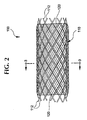
- An alternative embodiment of the stent-graft 100 is illustrated generally in Fig. 2 where the filaments 112 are exposed at each end and are not covered by the graft.
- the support function of the bioabsorbable stent 110 portion of the stent-graft 100 is temporary while the function of the graft 120 is generally permanent.
- the stent 110 is gradually absorbed and vessel compliance and functional stresses are generally transferred to the new tissue.
- the bioabsorbable stent 110 bioabsorbs over time and the generally compliant graft 120 and natural tissue remain in the vessel at the treatment site and form a composite vessel wall.
- the stent 110 is formed from helically wound elongated filaments 112 and is preferably made of a non-toxic bioabsorbable polymer such as PGA, PLA, polycaprolactone, or polydioxanone, and the graft 120 is preferably made of braided or film PET, ePTFE, PCU, or PU.
- a non-toxic bioabsorbable polymer such as PGA, PLA, polycaprolactone, or polydioxanone
- the graft 120 is preferably made of braided or film PET, ePTFE, PCU, or PU.
- the graft 120 is made of braided or interwoven material formed from fibers, strands, yams, mono-filaments, or multi-filaments and is adhered with an adhesive to at least a portion of the stent 110 .
- the graft 120 may also be formed from film, sheet, or tube.
- the especially preferred materials for the stent-graft 100 are PLLA for the bioabsorbable stent 110 and PET, PCU, or PU for the permanent graft 120 .
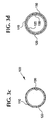
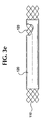
- Figs 3a-3e illustrating various embodiments of the stent-graft 100 .
- the graft 120 is preferably disposed on the inside surface of the bioabsorbable stent 110 as shown in Fig. 3c.
- the graft 120 may be attached to the outside of the bioabsorbable stent 110 as shown in Fig. 3a or the graft elements 144, 145 may be interbraided or woven with the stent filaments 112 as, for example, shown in Fig. 3b.
- the graft 120 may be disposed on the inside surface and the outside surface of the bioabsorbable stent 110 as shown in Fig. 3d.
- Figure 3e illustrates the stent-graft 100 with a cut-out showing both interior and exterior grafts 120 .
- the graft 120 and the stent 110 are adhered together at predetermined overlapping locations using an adhesive 130 .
- the stent-graft 100 may be advantageously used for the treatment of arterial fistulas and aneurysms.
- Stent 110 is made of a plurality of individually rigid, but, flexible and elastic filaments 112, each of which extends in a helix configuration along a longitudinal center line of the body as a common axis.
- the filaments 112 define a radially self-expanding body.
- the sets of filaments 112 are interwoven in an over and under braided configuration intersecting at points such as 114 to form an open mesh or weave construction.
- the stent 110 may be made with a first number of filaments 112 having a common direction of winding but axially displaced relative to each other, and crossing a second number of filaments 112 also axially displaced relative to each other but having an opposite direction of winding.
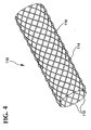
- Fig. 4 shows a stent 110 made of individual braided strands.
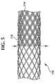
- Fig. 5 shows a stent 110 made of paired interbraided strands.
- a braid becomes a stent 110 after annealing.
- Annealing of the braid relaxes the stresses in the filaments and sets the shape of the stent 110.
- the term "braid angle” refers to the included angle between interbraided filaments of the braid in the axial orientation prior to annealing and the term “filament crossing angle” refers to the included angle of the stent after annealing.
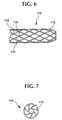
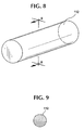
- the stent 110 may be made into various shapes, for example, as shown in Figures 6 and 7 where one end tapers and has a diameter which decreases in size.
- a tapered filament structure may be utilized as an intravascular filter or occlusion device.
- FIG. 8 shows a portion of a typical filament 112 which makes up a stent 110.
- Stent 110 is shown in its expanded state when subject to no external loads or stresses.
- the filaments 112 are resilient, permitting the radial compression of stent 110 into a reduced-radius, extended-length configuration suitable for delivery transluminally to the desired treatment site.
- Figure 9 illustrates a cross-sectional view of one embodiment of the bioabsorbable filaments 112 . As shown, the filaments 112 are substantially homogeneous in cross section.
- At least one and preferably all filaments 112 include one or more commercially available grades of polylactide, poly-L-lactide (PLLA), poly-D-lactide (PDLA), polyglycolide (PGA), polydioxanoe, polycaprolactone, polygluconate, polylactic acid-polyethylene oxide copolymers, modified cellulose, collagen, poly(hydroxybutyrate), polyanhydride, polyphosphoester, poly(amino acids), poly(alpha-hydroxy acid) or related coopolymers materials.
- PLLA poly-L-lactide
- PDLA poly-D-lactide
- PGA polyglycolide
- polydioxanoe polycaprolactone
- polygluconate polylactic acid-polyethylene oxide copolymers
- modified cellulose collagen
- polyanhydride polyphosphoester
- poly(amino acids) poly(alpha-hydroxy acid) or related coopolymers materials.
- a bioabsorbable stent is disclosed in United States Patent No. 6245103 issued on an Application entitled “Bioabsorbable Self-Expanding Stent", Serial No. 08/904,467, filed August 1, 1997.
- Another bioabsorbable stent is disclosed in United States Patent No. 5980564 issued on an Application entitled “Bioabsorbable Implantable Endoprosthesis With Reservoir And Method Of Using Same", Serial No. 08/905,806, filed August 1, 1997.
- a stent 110 may be made by braiding between 10-36 independent strands of 0.15-0.60 mm diameter bioabsorbable polymeric filament 112 interwoven into helical shape strands on a round bar mandrel of 3-30 mm diameter. One-half of the number of helical strands are wound clockwise and one-half are wound counterclockwise such that each clockwise helical strand is adjacent and interbraided with a counterclockwise strand.
- the tubular braid is made with strand braid angle of about 120-150 degrees and a pitch angle (angle between a filament and transverse axis of the stent) of about 15-30 degrees while on the braid bar mandrel.
- the braid is slid off of the braid bar and onto a 0.2-10 mm smaller diameter annealing bar or tube mandrel. Each end of the braid is pulled or compressed to cause axial tension or compression of the braid on the anneal mandrel, or left free. Each end of the braid is secured on each end of the anneal mandrel to fix the preset axial position of the braid, or left free.
- the braid is annealed on the anneal mandrel at a temperature between the glass-transition temperature and melting temperature of the bioabsorbable polymer for about 5-120 minutes in air, vacuum, or an inert atmosphere.
- the stent 110 is cooled on the anneal mandrel to about room temperature, slid off of the anneal mandrel, and cut to a desired length.
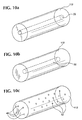
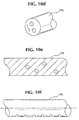
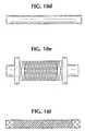
- Figs. 10a-10f In addition to substantially solid and homogenous filaments 112 , other embodiments of filaments 112 as shown in Figs. 10a-10f and having one or more reservoir portions including hollow 22 , cavity 32 , porous 42 portions, or combinations thereof can be used.
- the term "reservoir” is referred to as a volume of space internal to the filament outer surface where polymer degradation by-products accumulate.
- the reservoir may include both internal and external passages, with the external passages opening through an outside wall or end of the filament 112 .
- Fig. 10a illustrates a hollow filament 112 with a center core
- Fig. 10b illustrates a filament 112 having at least one cavity with sealed ends
- FIG. 10c illustrates a filament 112 having at least one pore (internal or external porosity, or both);
- Fig. 10d illustrates a multi-lumen filament 112 with a plurality of hollow portions;
- Fig. 10e illustrates a cross-section of a filament 112 having a plurality of internal pores;
- Fig. 10f illustrates a filament 112 having a plurality of surface pores.
- the external pores may connect with internal pores, cavities, or hollow portions.
- the reservoir portions have a size greater than about 1 micron and have a volume percentage greater than about 10%.
- Table I describes various preferred reservoir embodiments of filament 112 .
- Type of Reservoir % Volume Solid % Volume Hollow or Cavity Hollow or Cavity Features Dimensions axial core (one lumen tubing) 65-90 10-35 ⁇ 50% of O.D. x length of filament strand multi-lumen filament (two or more lumens) 50-90 10-40 ⁇ 50% of O.D./# of lumens, length of filament strand internal porosity 70-90 10-30 1-20 microns external porosity (surface oriented) 80-90 10-20 1-20 microns The degradation by-products in the reservoir portions may have an average pH level which decreases over time in vivo. The average pH level in the reservoir may be between about 3 and 7.
- the endoprosthesis may substantially degrades in vivo in less than 3 years.
- the filaments may comprise PLLA, PDLA, or combinations thereof and substantially degrade in vivo in from about 1 year to about 2 years.
- the filaments may comprise polylactide, polyglycolide, or combinations thereof and substantially degrade in vivo in from about 3 months to about 1 year.
- the filaments may comprise polyglycolide, polygluconate, polydioxanone, or combinations thereof and substantially degrade in vivo in from about 1 week to about 3 months.
- the filaments 112 may have an outer surface containing a multitude of empty pores which have an average depth of at least about 0.5 micron.
- the elongate filament 112 prior to implantation may contain at least one empty internal cavity which does not open to the filament 112 outer surface.
- the average cavity cross-sectional area is from about 2 to about 40 percent of the average filament 112 cross-sectional area.
- Tables II and III show various embodiments of the bioabsorbable stent 110 of the stent-graft 100 .
- a separately manufactured and permanent graft 120 is disposed on and adhered to a portion of the stent 110 with an adhesive to form the stent-graft 100 and is discussed in further detail below.
- the permanent graft 120 generally radially expands and contracts with the bioabsorbable stent 110 .
- Vascular grafts are shown, for example, in United States Patent No. 5,116,360.
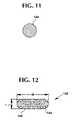
- Fig. 11 shows a cross-section of a mono-filament strand 144 which makes up a graft 120 .
- Strands can be woven, braided, or knitted into a tubular fabric shape.
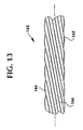
- Fig. 12 shows a cross-section of a multi-filament yarn 145.
- Figure 13 shows the yam 145 of Fig. 12 in a side elevation with a twist orientation.
- the graft 120 may include extruded or drawn tubes, films, or sheets.
- the graft 120 may include layers to make a composite structure with optimized porosity and mechanical properties.
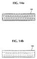
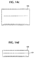
- FIG. 14a shows a tubular graft 120 , preferably made of PET
- Fig. 14b shows a tubular graft 120 , preferably made of extruded ePTFE, PCU, or PU
- Fig. 14c shows an ePTFE, PCU or PU film or sheet preferably formed in the shape of a tubular graft 120 with a butt joint or overlapping joint 121 as shown in Fig. 14d.
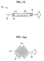
- Fig. 15 shows a stent-graft 100 with exposed filament end portions 46 and 48 which are used to facilitate long-term fixation of the stent-graft 100 ends with the vessel wall.
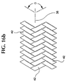
- Figures 16a-b show an exterior layer of stent-graft 100 as a textile sheeting or graft 120 , formed of multiple textile strands 42 and interwoven with one another.
- the textile strands 42 are shown braided in two embodiments in Figs. 16a and 16b. Other embodiments and patterns may also be used.
- the textile strands 42 intersect one another to define a braid angle ⁇ in a nominal state.
- Figures 15 and 16 show a filament crossing angle ⁇ on stent 110 and a angle ⁇ on graft 120 which bisects a longitudinal axis 38.
- Textile strands 42 preferably are multi-filament yams, although they may be mono-filaments. In either case, the textile strands are finer than the structural strands, and range from about 10 denier to 400 denier. Individual filaments of the multi-filament yams can range from about 0.25 to about 10 denier.
- the strands or yarns may be interbraided on a mandrel such that they intersect each other and form a braid angle.
- the number of strands or yams can range from 20 to 700.
- the graft 120 is preferably made of PET (Dacron) or polycarbonate urethane (PCU) such as CorethaneTM, however, other materials may include polypropylene (such as Spectra), polyurethane, HDPE, polyethylene, silicone, PTFE, polyolefins, and ePTFE.
- the multi-filament yearns are thermally set in generally the same manner as the bioabsorbable stent 110 .
- the graft 120 is thermally set, it is removed from the mandrel and washed ultrasonically or by agitation.
- the graft 120 is then cut to a desired length using a laser, which fused the ends of the strands to prevent unravelling.
- One preferred graft and method of making the same is a braided textile tubular sleeve that is adjustable between a nominal state and a radially-reduced axially-elongated state as described in United States Patent No. 5957974 issued on an Application entitled "Stent Graft With Braided Polymeric Sleeve", Serial No. 08/946,906 filed October 8, 1997 which claims the benefit of United States Provisional Application Serial No. 60/036,160, filed January 23, 1997.
- a device having a flexible tubular liner is disclosed in United States Patent No. 4,681,110.
- Several composite braided structures are shown in International Patent Publications Nos. WO 91/10766; WO 92/16166; WO 94/06372; and WO 94/06373.
- the graft 120 may be formed of an expandable uniaxially or biaxially oriented polytetrafluoroethylene tube having a microstructure of nodules and fibrils as described in EP 0775472 A2.
- Table IV illustrates several examples of braided textiles fabric grafts having strands with a packing factor of 0.54, and, preferably, a braid angle of about 110 degrees.
- a coating can be applied to the yam to enhance surface properties of the yarn and reduce friction.
- Adhesives 130 and methods of manufacturing the stent-graft 100 are discussed in further detail below.
- a variety of methods and adhesives 130 may be used for bonding the graft 120 to the bioabsorbable structural support 110 are possible.
- the methods below reference PLLA material however, other bioabsorbable materials may be used accordingly.
- a siloxane polymer (silicone) may be used as an adhesive.
- Other alternative polymers may include fluorosilicone and polycarbonate urethane.
- a first method includes application of a thermoplastic adhesive to the surface of the PLLA braid by spraying the PLLA braid with a solution of polyurethane or thermoplastic adhesive dissolved in an organic solvent.
- the graft is disposed over a mandrel and the stent is disposed over the graft.
- the assembly is heated in an oven at a temperature above the softening temperature of the thermoplastic adhesive and below the melting point of PLLA.
- the PLLA braid will shrink to the diameter of the mandrel, and make intimate contact with the graft and bond to the graft.
- the PLLA braid is preferably made such that the braid angle about matches the braid angle of the graft.
- Adhesives include the polycarbonate urethanes disclosed in U.S. Patent No. 5,229,431.
- a second method includes braiding extruded PLLA filaments to form a tubular interwoven braid and annealing the braid to the desired braid angle and diameter. Apply a thermoplastic adhesive to the surface of the PLLA mesh. Dispose the braid and graft on a mandrel such that the graft is on the interior and/or exterior of the braid. Apply radial compression or axial elongation to the composite to create intimate contact between the layers.
- One preferred method of applying radial compression to the structure uses fluorinated ethylene propylene (FEP) "heat-shrink" tubing which reduces in diameter when heated above its glass transition temperature. Bond the composite layers by heating the structure to a temperature above the glass transition temperature of the heat shrink tubing, and below the melting point of the PLLA filaments.
- FEP fluorinated ethylene propylene
- a third method includes braiding extruded PLLA filaments to form a tubular interwoven braid, and anneal the braid to the desired braid angle and diameter. Apply a coating of curable adhesive to the surface of the braid. Disposing the graft on the interior and/or exterior of the braid such that at least a portion of the graft is in contact with the curable adhesive. Heat the composite at a temperature between the cure temperature of the curable adhesive and the glass transition temperature of the PLLA braid.
- a fourth method includes braiding extruded PLLA filaments to form a tubular interwoven braid, and annealing the braid to the desired braid angle and diameter.
- a fifth method includes braiding extruded PLLA filaments to form a tubular interwoven braid, and annealing the braid to the desired braid angle and diameter. Apply a coating of a bioabsorbable polymer "glue" to the surface of the braid. Placing the graft on the interior and/or exterior of the braid. Bond the braid to the graft by heating the structure to a temperature above the melting point of the polymer "glue” and below the glass transition temperature of the PLLA braid. This method may also utilize heat shrink as provided in the second method.
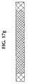
- a first method is shown in Figures 17A-17G.
- the steps include providing extruded PLLA filament as shown in Fig. 17A.
- Fig. 17B shows braiding of extruded filaments to form a tubular interwoven braid.
- Fig. 17C shows the braid off the mandrel with a braid angle from about 120 to 150 degrees and a diameter of about 11 mm.
- Fig. 17D shows a straight tubular anneal mandrel, preferably with about a 9 mm diameter.
- Fig. 17E shows the braid being axially compressed in the anneal mandrel to a diameter of about 11.5 mm.
- the braid is annealed at a temperature between the glass transition temperature and melting point of the bioabsorbable PLLA filament for 15 minutes in a recirculating air oven.
- the braid will shrink onto the surface of the mandrel during the annealing cycle.
- the braid can be designed to shrink to a desired diameter and desired filament crossing angle.
- Fig. 17F shows the annealed stent off the anneal mandrel with a filament crossing angle from about 130 to 150 degrees.
- the graft is adhered to the annealed stent using a bioabsorbable adhesive while matching within about plus or minus 5° of the graft braid angle to the annealed stent filament crossing angle.
- FIG. 18A-18F A second method is shown in Figures 18A-18F.
- the steps include providing extruded PLLA filament as shown in Fig. 18A.
- Fig. 18B shows braiding of extruded filaments to form a tubular interwoven braid.
- Fig. 18C shows the braid off the mandrel with a braid angle from about 120 to 150 degrees and a diameter of about 11 mm.
- Fig. 18D shows a straight tubular anneal mandrel, preferably with about a 9 mm diameter.
- FIG. 18E shows the braid and graft being axially compressed in the anneal mandrel to a diameter of about 11.5 mm and being adhered together using a bioabsorbable adhesive while matching within about plus or minus 5° of the graft braid angle to about the braid angle.
- the braid-graft is annealed at a temperature between the glass transition temperature and melting point of the bioabsorbable PLLA filament for 15 minutes in a recirculating air oven.
- the braid-graft will shrink onto the surface of the mandrel during the annealing cycle.
- the braid-graft can be designed to shrink to a desired diameter and filament crossing angle.
- Fig. 18F shows the annealed stent-graft off the anneal mandrel with a filament crossing angle from about 130 to 150 degrees.
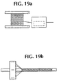
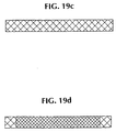
- a third method is shown in Figures 19A-19D.
- the steps include providing extruded PLLA filament as shown in Fig. 19A and annealing unconstrained PLLA filaments at a temperature between the glass transition temperature and the melting point for 15 minutes in a recirculating air oven.
- Fig. 19B shows braiding of extruded annealed filaments to form a tubular interwoven braid.
- Fig. 19C shows the stent off the mandrel with a filament crossing angle from about 120 to 150 degrees and a diameter of about 10 mm.
- Fig. 19D shows the stent and graft being adhered together using a bioabsorbable adhesive while matching within about 5° the graft braid angle to about the filament crossing angle.
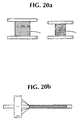
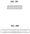
- FIG. 20A-20F A fourth method is shown in Figures 20A-20F.
- the steps include providing extruded PLLA filament and graft fiber as shown in Fig. 20A.
- Fig. 20B shows co-braiding of extruded filaments and graft to form a tubular interwoven braid-graft.
- Fig. 20C shows the braid-graft off the mandrel with a braid angle from about 120 to 150 degrees and a diameter of about 11 mm.
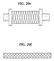
- Fig. 20D shows a straight tubular anneal mandrel, preferably with about a 9 mm diameter.
- Fig. 20E shows the braid-graft being axially compressed on the anneal mandrel to a diameter of about 11.5 mm.
- 20F shows the braid-graft is annealed at a temperature between the glass transition temperature and metting point of the bioabsorbable PLLA filament for 15 minutes in a recirculating air oven.
- the braid-graft will shrink onto the surface of the mandrel during the annealing cycle.
- the braid-graft can be designed to shrink to a desired diameter and filament crossing angle.
- Tne annealed stent-graft is removed from the anneal mandrel with a filament crossing angle from about 130 to 150 degrees and a diameter of about 10 mm.
- the interbraiding of PLLA filaments and graft material forms an interwoven tubular mesh with a desired porosity.
- the graft 120 may surround the outside surface of stent 110 or the stent 110 may surround the outside surface of graft 120 . In another embodiment, two grafts 120 may be used to surround and sandwich the stent 110 .
- the filament crossing angle of the assembly generally determines the relationship between radial compression and axial elongation of the stent-graft 100 . Smaller angles generally result in less axial shortening for a given amount of radial enlargement.
- the graft 120 is highly compliant and conforms to changes in the shape of the stent 110 .
- a primary consideration is to select a braid angle ⁇ of the graft 120 with respect to a braid angle ⁇ of the stent 110, and to closely match the geometrical diameter and elongation properties of the stent 110 and graft 120 formed into the stent-graft 100 by about matching the respective braid angles.
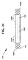
- Figure 21 shows a stent-graft 100 with portions of exposed ends 100A and 100B of the stent 110 coated with adhesive 130 .
- Bond regions 120A and 120B have axial lengths, preferably of about 17 mm, where the stent 110 and graft 120 are coated with adhesive 130 and bonded together.
- Over a medial region 120C the graft 120 and stent 110 are adjacent one another and in surface contact, but not bonded.
- Figure 22 shows a stent-graft 100 with a stent 110 surrounded by proximal and distal grafts 120.
- the stent 110 is exposed at stent-graft end portions 110A, 110B.
- Each of the grafts 120 is positionable along an intraluminal location where shunting of the blood flow is desired.
- An exposed medial region 110C between grafts 120 is positionable in alignment with a branch of the vessel being treated, so that stent-graft 100 can provide the intended shunting without blocking flow between the main vessel and the branch between the two shunting areas.
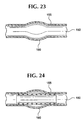
- Figure 23 shows an artery lumen 150 , artery wall 155 and an untreated arterial aneurysm 160.
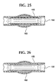
- Figures 24-26 schematically show the stent-graft 100 as it is intended to function in-vivo at a treatment site, for example, an aneurysm.
- Figure 24 shows a stent-graft 100 implanted in a artery lumen 150 and within or over an aneurysm 160 .
- Figure 25 shows healing occurring around the stent-graft 100 with exclusion of the aneurysm 160 .
- Figure 26 shows the bioabsorbable stent 110 has absorbed and that the graft 120 remains in the artery lumen 150 and has become incorporated in the artery wall 155 .
- Stent-graft 100 offers considerable advantages.
- the polymers from which it is formed are highly biocompatible and exhibit good resistance to thrombosis and bacteria adhesion.
- Stent-graft 100 can be fabricated from a stent 110 having 10 filament strands of 0.15-0.25 mm diameter PLLA, PDLA, PLLA-PDLA copolymer, 0.20-0.30 mm diameter PGA, PGA-PLLA copolymer, 0.22-0.32 mm diameter PGA-polycaprolactone copolymer, PGA-trimethylcarbonate copolymer, or 0.25-0.35 mm diameter polydioxanone on a 3-6 mm diameter braid mandrel with a filament braid angle of 120-150 degrees while the braid is on the braid mandrel.
- the braid is annealed on a bar or tube mandrel that has an outer diameter 0.2-3 mm smaller than the braid mandrel diameter at a temperature between the polymer glass-transition temperature and the melting temperature for 5-120 minutes in air, vacuum, or inert atmosphere with the braid in an axially extended, free, or contracted position.
- the stent is cooled to about room temperature, slid off the anneal mandrel, cut to the desired stent length, and adhered to a graft 120 made of one of PET, ePTFE, PCU, or PU.
- the stent-graft 100 may be loaded onto a delivery system at least 6 French in size.
- Stent-graft 100 can be fabricated from a stent 110 having 10 filament strands of 0.20-0.30 mm diameter PLLA, PDLA, PLLA-PDLA copolymer, 0.25-0.35 mm diameter PGA, PGA-PLLA copolymer, 0.27-0.37 mm diameter PGA-polycaprolactone copolymer, PGA-trimethylcarbonate copolymer, or 0.30-0.40 mm diameter polydioxanone on a 3-6 mm diameter braid mandrel with a filament braid angle of 120-150 degrees while the braid is on the braid mandrel.
- the braid is annealed on a bar or tube mandrel that has an outer diameter 0.2-3 mm smaller than the braid mandrel diameter at a temperature between the polymer glass-transition temperature and the melting temperature for 5-120 minutes in air, vacuum, or inert atmosphere with the braid in an axially extended, free, or contracted position.
- the stent is cooled to about room temperature, slid off the anneal mandrel, cut to the desired stent length, and adhered to a graft 120 made of one of PET, ePTFE, PCU, or PU.
- the stent-graft 100 may be loaded onto a delivery system at least 8 French in size.
- Stent-graft 100 can be fabricated from a stent 110 having 12 filament strands of 0.20-0.30 mm diameter PLLA, PDLA, PLLA-PDLA copolymer, 0.25-0.35 mm diameter PGA, PGA-PLLA copolymer, 0.27-0.37 mm diameter PGA-polycaprolactone copolymer, PGA-trimethylcarbonate copolymer, or 0.30-0.40 mm diameter polydioxanone on a 3-8 mm diameter braid mandrel with a filament braid angle of 120-150 degrees while the braid is on the braid mandrel.
- the braid is annealed on a bar or tube mandrel that has an outer diameter 0.2-3 mm smaller than the braid mandrel diameter at a temperature between the polymer glass-transition temperature and the melting temperature for 5-120 minutes in air, vacuum, or inert atmosphere with the braid in an axially extended, free, or contracted position.
- the stent is cooled to about room temperature, slid off the anneal mandrel, cut to the desired stent length, and adhered to a graft 120 made of one of PET, ePTFE, PCU, or PU.
- the stent-graft 100 may be loaded onto a delivery system at least 8 French in size.
- Stent-graft 100 can be fabricated from a stent 110 having 12 filament strands of 0.35-0.45 mm diameter PLLA, PDLA, PLLA-PDLA copolymer, 0.40-0.50 mm diameter PGA, PGA-PLLA copolymer, 0.42-0.52 mm diameter PGA-polycaprolactone copolymer, PGA-trimethylcarbonate copolymer, or 0.45-0.55 mm diameter polydioxanone on a 3-8 mm diameter braid mandrel with a filament braid angle of 120-150 degrees while the braid is on the braid mandrel.
- the braid is annealed on a bar or tube mandrel that has an outer diameter 0.2-3 mm smaller than the braid mandrel diameter at a temperature between the polymer glass-transition temperature and the melting temperature for 5-120 minutes in air, vacuum, or inert atmosphere with the braid in an axially extended, free, or contracted position.
- the stent is cooled to about room temperature, slid off the anneal mandrel, cut to the desired stent length, and adhered to a graft 120 made of one of PET, ePTFE, PCU, or PU.
- the stent-graft 100 may be loaded onto a delivery system at least 11 French in size.
- Stent-graft 100 can be fabricated from a stent 110 having 16 filament strands of 0.30-0.40 mm diameter PLLA, PDLA, PLLA-PDLA copolymer, 0.35-0.45 mm diameter PGA, PGA-PLLA copolymer, 0.37-0.47 mm diameter PGA-polycaprolactone copolymer, PGA-trimethylcarbonate copolymer, or 0.40-0.50 mm diameter polydioxanone on a 6-10 mm diameter braid mandrel with a filament braid angle of 120-150 degrees while the braid is on the braid mandrel.
- the braid is annealed on a bar or tube mandrel that has an outer diameter 0.2-3 mm smaller than the braid mandrel diameter at a temperature between the polymer glass-transition temperature and the melting temperature for 5-120 minutes in air, vacuum, or inert atmosphere with the braid in an axially extended, free, or contracted position.
- the stent is cooled to about room temperature, slid off the anneal mandrel, cut to the desired stent length, and adhered to a graft 120 made of one of PET, ePTFE, PCU, or PU.
- the stent-graft 100 may be loaded onto a delivery system at least 9 French in size.
- Stent-graft 100 can be fabricated from a stent 110 having 16 filament strands of 0.35-0.45 mm diameter PLLA, PDLA, PLLA-PDLA copolymer, 0.40-0.50 mm diameter PGA, PGA-PLLA copolymer, 0.42-0.52 mm diameter PGA-polycaprolactone copolymer, PGA-trimethylcarbonate copolymer, or 0.45-0.55 mm diameter polydioxanone on a 6-10 mm diameter braid mandrel with a filament braid angle of 120-150 degrees while the braid is on the braid mandrel.
- the braid is annealed on a bar or tube mandrel that has an outer diameter 0.2-3 mm smaller than the braid mandrel diameter at a temperature between the polymer glass-transition temperature and the melting temperature for 5-120 minutes in air, vacuum, or inert atmosphere with the braid in an axially extended, free, or contracted position.
- the stent is cooled to about room temperature, slid off the anneal mandrel, cut to the desired stent length, and adhered to a graft 120 made of one of PET, ePTFE, PCU, or PU.
- the stent-graft 100 may be loaded onto a delivery system at least 11 French in size.
- Stent-graft 100 can be fabricated from a stent 110 having 18 filament strands of 0.35-0.45 mm diameter PLLA, PDLA, PLLA-PDLA copolymer, 0.40-0.50 mm diameter PGA, PGA-PLLA copolymer, 0.42-0.52 mm diameter PGA-polycaprolactone copolymer, PGA-trimethylcarbonate copolymer, or 0.45-0.55 mm diameter polydioxanone on a 7-12 mm diameter braid mandrel with a filament braid angle of 120-150 degrees while the braid is on the braid mandrel.
- the braid is annealed on a bar or tube mandrel that has an outer diameter 0.2-3 mm smaller than the braid mandrel diameter at a temperature between the polymer glass-transition temperature and the melting temperature for 5-120 minutes in air, vacuum, or inert atmosphere with the braid in an axially extended, free, or contracted position.
- the stent is cooled to about room temperature, slid off the anneal mandrel, cut to the desired stent length, and adhered to a graft 120 made of one of PET, ePTFE, PCU, or PU.
- the stent-graft 100 may be loaded onto a delivery system at least 11 French in size.
- Stent-graft 100 can be fabricated from a stent 110 having 18 filament strands of 0.40-0.50 mm diameter PLLA, PDLA, PLLA-PDLA copolymer, 0.45-0.55 mm diameter PGA, PGA-PLLA copolymer, 0.47-0.57 mm diameter PGA-polycaprolactone copolymer, PGA-trimethylcarbonate copolymer, or 0.50-0.60 mm diameter polydioxanone on a 7-12 mm diameter braid mandrel with a filament braid angle of 120-150 degrees while the braid is on the braid mandrel.
- the braid is annealed on a bar or tube mandrel that has an outer diameter 0.2-3 mm smaller than the braid mandrel diameter at a temperature between the polymer glass-transition temperature and the melting temperature for 5-120 minutes in air, vacuum, or inert atmosphere with the braid in an axially extended, free, or contracted position.
- the stent is cooled to about room temperature, slid off the anneal mandrel, cut to the desired stent length, and adhered to a graft 120 made of one of PET, ePTFE, PCU, or PU.
- the stent-graft 100 may be loaded onto a delivery system at least 13 French in size.
- Stent-graft 100 can be fabricated from a stent 110 having 20 filament strands of 0.20-0.30 mm diameter PLLA, PDLA, PLLA-PDLA copolymer, 0.25-0.35 mm diameter PGA, PGA-PLLA copolymer, 0.27-0.37 mm diameter PGA-polycaprolactone copolymer, PGA-trimethylcarbonate copolymer, or 0.30-0.40 mm diameter polydioxanone on a 3-9 mm diameter braid mandrel with a filament braid angle of 120-150 degrees while the braid is on the braid mandrel.
- the braid is annealed on a bar or tube mandrel that has an outer diameter 0.2-3 mm smaller than the braid mandrel diameter at a temperature between the polymer glass-transition temperature and the melting temperature for 5-120 minutes in air, vacuum, or inert atmosphere with the braid in an axially extended, free, or contracted position.
- the stent is cooled to about room temperature, slid off the anneal mandrel, cut to the desired stent length, and adhered to a graft 120 made of one of PET, ePTFE, PCU, or PU.
- the stent-graft 100 may be loaded onto a delivery system at least 8 French in size.
- Stent-graft 100 can be fabricated from a stent 110 having 24 filament strands of 0.20-0.30 mm diameter PLLA, PDLA, PLLA-PDLA copolymer, 0.25-0.35 mm diameter PGA, PGA-PLLA copolymer, 0.27-0.37 mm diameter PGA-polycaprolactone copolymer, PGA-trimethylcarbonate copolymer, or 0.30-0.40 mm diameter polydioxanone on a 8-12 mm diameter braid mandrel with a filament braid angle of 120-150 degrees while the braid is on the braid mandrel.
- the braid is annealed on a bar or tube mandrel that has an outer diameter 0.2-3 mm smaller than the braid mandrel diameter at a temperature between the polymer glass-transition temperature and the melting temperature for 5-120 minutes in air, vacuum, or inert atmosphere with the braid in an axially extended, free, or contracted position.
- the stent is cooled to about room temperature, slid off the anneal mandrel, cut to the desired stent length, and adhered to a graft 120 made of one of PET, ePTFE, PCU, or PU.
- the stent-graft 100 may be loaded onto a delivery system at least 9 French in size.
- Stent-graft 100 can be fabricated from a stent 110 having 24 filament strands of 0.25-0.35 mm diameter PLLA, PDLA, PLLA-PDLA copolymer, 0.30-0.40 mm diameter PGA, PGA-PLLA copolymer, 0.32-0.42 mm diameter PGA-polycaprolactone copolymer, PGA-trimethylcarbonate copolymer, or 0.35-0.45 mm diameter polydioxanone on a 9-14 mm diameter braid mandrel with a filament braid angle of 120-150 degrees while the braid is on the braid mandrel.
- the braid is annealed on a bar or tube mandrel that has an outer diameter 0.2-3 mm smaller than the braid mandrel diameter at a temperature between the polymer glass-transition temperature and the melting temperature for 5-120 minutes in air, vacuum, or inert atmosphere with the braid in an axially extended, free, or contracted position.
- the stent is cooled to about room temperature, slid off the anneal mandrel, cut to the desired stent length, and adhered to a graft 120 made of one of PET, ePTFE, PCU, or PU.
- the stent-graft 100 may be loaded onto a delivery system at least 11 French in size.
- Stent-graft 100 can be fabricated from a stent 110 having 24 filament strands of 0.30-0.40 mm diameter PLLA, PDLA, PLLA-PDLA copolymer, 0.35-0.45 mm diameter PGA, PGA-PLLA copolymer, 0.37-0.47 mm diameter PGA-polycaprolactone copolymer, PGA-trimethylcarbonate copolymer, or 0.40-0.50 mm diameter polydioxanone on a 12-18 mm diameter braid mandrel with a filament braid angle of 120-150 degrees while the braid is on the braid mandrel.
- the braid is annealed on a bar or tube mandrel that has an outer diameter 0.2-3 mm smaller than the braid mandrel diameter at a temperature between the polymer glass-transition temperature and the melting temperature for 5-120 minutes in air, vacuum, or inert atmosphere with the braid in an axially extended, free, or contracted position.
- the stent is cooled to about room temperature, slid off the anneal mandrel, cut to the desired stent length, and adhered to a graft 120 made of one of PET, ePTFE, PCU, or PU.
- the stent-graft 100 may be loaded onto a delivery system at least 12 French in size.
- Stent-graft 100 can be fabricated from a stent 110 having 30 filament strands of 0.30-0.40 mm diameter PLLA, PDLA, PLLA-PDLA copolymer, 0.35-0.45 mm diameter PGA, PGA-PLLA copolymer, 0.37-0.47 mm diameter PGA-polycaprolactone copolymer, PGA-trimethylcarbonate copolymer, or 0.40-0.50 mm diameter polydioxanone on a 16-26 mm diameter braid mandrel with a filament braid angle of 120-150 degrees while the braid is on the braid mandrel.
- the braid is annealed on a bar or tube mandrel that has an outer diameter 0.2-6 mm smaller than the braid mandrel diameter at a temperature between the polymer glass-transition temperature and the melting temperature for 5-120 minutes in air, vacuum, or inert atmosphere with the braid in an axially extended, free, or contracted position.
- the stent is cooled to about room temperature, slid off the anneal mandrel, cut to the desired stent length, and adhered to a graft 120 made of one of PET, ePTFE, PCU, or PU.
- the stent-graft 100 may be loaded onto a delivery system at least 15 French in size.
- Stent-graft 100 can be fabricated from a stent 110 having 36 filament strands of 0.35-0.45 mm diameter PLLA, PDLA, PLLA-PDLA copolymer, 0.40-0.50 mm diameter PGA, PGA-PLLA copolymer, 0.42-0.52 mm diameter PGA-polycaprolactone copolymer, PGA-trimethylcarbonate copolymer, or 0.45-0.55 mm diameter polydioxanone on a 20-30 mm diameter braid mandrel with a filament braid angle of 120-150 degrees while the braid is on the braid mandrel.
- the braid is annealed on a bar or tube mandrel that has an outer diameter 0.2-6 mm smaller than the braid mandrel diameter at a temperature between the polymer glass-transition temperature and the melting temperature for 5-120 minutes in air, vacuum, or inert atmosphere with the braid in an axially extended, free, or contracted position.
- the stent is cooled to about room temperature, slid off the anneal mandrel, cut to the desired stent length, and adhered to a graft 120 made of one of PET, ePTFE, PCU, or PU.
- the stent-graft 100 may be loaded onto a delivery system at least 19 French in size.
- Stent-graft 100 can be fabricated from a stent 110 having 24 filament strands of 0.35-0.45 mm diameter PLLA, PDLA, PLLA-PDLA copolymer, 0.40-0.50 mm diameter PGA, PGA-PLLA copolymer, 0.42-0.52 mm diameter PGA-polycaprolactone copolymer, PGA-trimethylcarbonate copolymer, or 0.45-0.55 mm diameter polydioxanone on a 14-20 mm diameter braid mandrel with a filament braid angle of 120-150 degrees while the braid is on the braid mandrel.
- the braid is annealed on a bar or tube mandrel that has an outer diameter 0.2-6 mm smaller than the braid mandrel diameter at a temperature between the polymer glass-transition temperature and the melting temperature for 5-120 minutes in air, vacuum, or inert atmosphere with the braid in an axially extended, free, or contracted position.
- the stent is cooled to about room temperature, slid off the anneal mandrel, cut to the desired stent length, and adhered to a graft 120 made of one of PET, ePTFE, PCU, or PU.
- the stent-graft 100 may be loaded onto a delivery system at least 15 French in size.
- Tables V-VIII show various embodiments of stent-graft 100 .
- Braid Mandrel Dia., mm Bioabsortable Strands In Braid Bioabsorbable Filament Dia., mm Bioabsorbable Braid Angle Deg. Anneal Mandrel Dia., mm Annealed Stent I.D., mm Annealed Stent Filament Crossing Angle, Deg. Graft Braid Mandrel Dia., mm Strands In Graft Braid Graft Yarn Denier Graft Braid Angle, Deg.
- Anneal Mandrel Dia. mm Annealed Stent I.D., mm Annealed Stent Filament Crossing Angle, Deg. Graft Braid Mandrel Dia., mm Strands In Graft Braid Graft Yarn Denier Graft Braid Angle, Deg.
- Graft Yarn Denier Graft Braid Angle Deg. Anneal Mandrel Dia., mm Annealed Stent I.D., mm Annealed stent Filament Crossing Angle.
- Graft Braid Angle Deg.
- Another embodiment of the stent-graft 100 includes at least one bioabsorbable-radiopaque marker strand disposed thereon to visualize the position of the stent-graft 100 through fluoroscopy during implantation.
- Bioabsorbable markers that may advantageously be used in conjunction with the present invention are disclosed in United States Patent No. 6340367 issued on an Application entitled “Radiopaque Markers And Methods Of Using Same", Serial No. 08/905821 and US Patent No. 6174330 entitled “Bioabsorbable Marker Having Radiopaque Constituents And Method Of Using Same", Serial No. 08/904,951 both filed August 1, 1997.
- a delivery device is used for delivering the stent-graft 100 to a treatment site in a body vessel.
- the delivery device 140 generally includes an elongate and flexible outer catheter 20 constructed of a biocompatible polymer such as polyurethane.
- a central lumen 22 runs the length of catheter 20 .
- a distal end region 24 of the outer catheter surrounds stent-graft 100 .
- An inner catheter 26 is contained within lumen 22 and runs along the entire length of the outer catheter.
- inner catheter 26 At the distal end of inner catheter 26 is a tapered distal tip 28 which extends beyond the outer catheter. Stent-graft 100 surrounds inner catheter 26, confined between the inner and outer catheters. A lumen 30 in the inner catheter can accommodate a flexible guidewire (not shown) tracked by delivery device 140 as it is advanced toward the treatment site.
- Stent-graft 100 may be placed on the delivery device 140 in a radially compressed state.
- Preferred delivery devices are shown in United States Patent Nos. 4,954,126 and 5,026,377.
- Alternative delivery devices are shown in United States Patent No. 5,201,757; 5,484,444; 5,591,172; 5,628,755; and 5,662,703.
- Suitable materials for use with such delivery devices are described in United States Patent No. 6042578 issued on Application Serial No. 08/833,639, filed April 8, 1997.
- a pusher-type delivery system provides generally greater self-expansion of the stent-graft 100 than a coaxial inner-outer tube-type delivery system. Pushing the proximal end of the stent-graft 100 out the distal end of the delivery system results in more self expansion than when the stent is released by sliding back the outer tube of the catheter delivery system.
- the preferred delivery system size for stent-graft 100 is the extemal diameter in French size of about 7-20 French (French size is equivalent to about three times the diameter in mm).
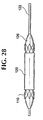
- FIG. 28 An alternative delivery device is shown in Figure 28 where a distal end region of a catheter 122 is used to deploy the stent-graft 100 .
- Stent-graft 100 is designed to remain in the axially elongated, radially reduced delivery state as shown, without additional constraining features.
- An auxiliary forcing feature is required to urge the stent-graft 100 , once properly positioned at a treatment site, toward its normal state.
- a dilatation balloon 126 is mounted to catheter 122 and surrounded by the stent-graft 100 . The balloon 126 , when inflated by the introduction of fluid under pressure through a lumen in catheter 122 , radially expands the stent-graft 100 .
- bioabsorbable self-expanding stent-graft 100 may be constructed using a number of method and materials, in a wide variety of sizes and styles for the greater efficiency and convenience of a user.
Description
| Type of Reservoir: | % Volume Solid | % Volume Hollow or Cavity | Hollow or Cavity Features Dimensions |
| axial core (one lumen tubing) | 65-90 | 10-35 | Ø<50% of O.D. x length of filament strand |
| multi-lumen filament (two or more lumens) | 50-90 | 10-40 | Ø<50% of O.D./# of lumens, length of filament strand |
| internal porosity | 70-90 | 10-30 | 1-20 microns |
| external porosity (surface oriented) | 80-90 | 10-20 | 1-20 microns |
| # of Filament Strands In Stent | Braid Mandrel Diameter, mm | Braid Angle, Degrees | PLLA Diameter mm | PDLA Diameter, mm | PLLA/PDLA Diameter, mm | PGA Diameter, mm |
| 10 | 3-6 | 120-150 | .15-.25 | .15-.25 | .15-.25 | .20-.30 |
| 10 | 3-6 | 120-150 | .20-.30 | .20-.30 | .20-.30 | .25-.35 |
| 12 | 3-8 | 120-150 | .20-.30 | .20-.30 | .20-.30 | .25-.35 |
| 12 | 3-8 | 120-150 | .35-.45 | .35-.45 | .35-.45 | .40-.50 |
| 15 | 6-10 | 120-150 | .30-.40 | .30-.40 | .30-.40 | .35-.45 |
| 15 | 6-10 | 120-150 | .35-.45 | .35-.45 | .35-.45 | .40-.50 |
| 18 | 7-12 | 120-150 | .35-.45 | .35-.45 | .35-.45 | .40-.50 |
| 18 | 7-12 | 120-150 | .40-.50 | .40-.50 | .40-.50 | .45-.55 |
| 20 | 3-9 | 120-150 | .20-.30 | .20-.30 | .20-.30 | .25-.35 |
| 24 | 8-12 | 120-150 | .20-.30 | .20-.30 | .20-.30 | .25-.35 |
| 24 | 9-14 | 120-150 | .25-.35 | .25-.35 | .25-.35 | .30-.40 |
| 24 | 12-18 | 120-150 | .30-.40 | .30-.40 | .30-.40 | .35-.45 |
| 30 | 16-26 | 120-150 | .30-.40 | .30-.40 | .30-.40 | .35-.45 |
| 36 | 20-30 | 120-150 | .35-.45 | .35-.45 | .35-.45 | .40-.50 |
| 24 | 14-20 | 120-150 | .35-.45 | .35-.45 | .35-.45 | .40-.50 |
| # of filament strands in braid | braid mandrel diameter, mm | braid angle, degrees | PGA/PLLA diameter, mm | PGA/polycaprolactone diameter, mm | Polydioxanone diameter, mm | PGA/trimethylene carbonate diameter, mm |
| 10 | 3-6 | 120-150 | .20-.30 | .22-.32 | .25-.35 | .22-.32 |
| 10 | 3-6 | 120-150 | .25-.35 | .27-.37 | .30-.40 | .27-.37 |
| 12 | 3-8 | 120-150 | .25-.35 | .27-.37 | .30-.40 | .27-.37 |
| 12 | 3-8 | 120-150 | .40-.50 | .42-.52 | .45-.55 | .42-.52 |
| 15 | 6-10 | 120-150 | .35-.45 | .37-.47 | .40-.50 | .37-.47 |
| 15 | 6-10 | 120-150 | .40-.50 | .42-.52 | .45-.55 | .42-.52 |
| 18 | 7-12 | 120-150 | .40-.50 | .42-.52 | .45-.55 | .42-.52 |
| 18 | 7-12 | 120-150 | .45-.55 | .47-.57 | .50-.60 | .47-.57 |
| 20 | 3-9 | 120-150 | .25-.35 | .27-.37 | .30-.40 | .27-.37 |
| 24 | 8-12 | 120-150 | .25-.35 | .27-.37 | .30-.40 | .27-.37 |
| 24 | 9-14 | 120-150 | .30-.40 | .32-.42 | .35-.45 | .32-.42 |
| 24 | 12-18 | 120-150 | .35-.45 | .37-.47 | .40-.50 | .37-.47 |
| 30 | 16-26 | 120-150 | .35-.45 | .37-.47 | .40-.50 | .37-.47 |
| 36 | 20-30 | 120-150 | .40-.50 | .42-.52 | .45-.55 | .42-.52 |
| 24 | 14-20 | 120-150 | .40-.50 | .42-.52 | .45-.55 | .42-.52 |
| Inner Diameter, mm | # of Yarn Ends | Yarn Linear Density | Fabric Thickness, inch | Yarn Coverage, % | Fabric Porosity, % | Yarn Aspect Ratio |
| 6 | 72 | 70 | 0.0787 (.0031) | 98 | 55 | 6.53 |
| 6 | 96 | 50 | 0.0813 (.0032) | 97 | 58 | 4.62 |
| 6 | 120 | 40 | 0.0864 (.0034) | 94 | 62 | 3.15 |
| 6 | 144 | 30 | 0.0813 (.0032) | 93 | 64 | 2.69 |
| 12 | 192 | 50 | 0.0813 (.0032) | 97 | 58 | 4.62 |
| 24 | 352 | 60 | 0.0819 (.0035) | 97 | 58 | 4.56 |
| 40 | 512 | 70 | 0.0864 (.0034) | 98 | 56 | 5.45 |
| Braid Mandrel Dia., mm | Bioabsortable Strands In Braid | Bioabsorbable Filament Dia., mm | Bioabsorbable Braid Angle, Deg. | Anneal Mandrel Dia., mm | Annealed Stent I.D., mm | Annealed Stent Filament Crossing Angle, Deg. | Graft Braid Mandrel Dia., mm | Strands In Graft Braid | Graft Yarn Denier | Graft Braid Angle, Deg. |
| 8 | 24 | 0.25 | 130-135 | 6 | 6.0 | 105-115 | 6.5 | 120 | 40 | 105-115 |
| 10 | 24 | 0.25 | 130-135 | 7 | 7.0 | 105-115 | 7.5 | 120 | 50 | 105-115 |
| 10 | 24 | 0.25 | 130-135 | 8 | 8.0 | 105-115 | 8.5 | 120 | 50 | 105-115 |
| 12 | 24 | 0.25 | 130-135 | 9 | 9.0 | 105-115 | 9.5 | 120 | 60 | 105-115 |
| 12.5 | 24 | 0.25 | 130-135 | 10 | 10.0 | 105-115 | 10.5 | 192 | 40 | 105-115 |
| 14 | 24 | 0.30 | 130-135 | 12 | 12.0 | 105-115 | 12.5 | 192 | 50 | 105-115 |
| 22 | 36 | 0.35 | 130-135 | 20 | 20.0 | 105-115 | 20.5 | 352 | 40 | 105-115 |
| 25.8 | 36 | 0.40 | 130-135 | 22 | 22.0 | 105-115 | 22.5 | 352 | 50 | 105-115 |
| 28 | 36 | 0.40 | 130-135 | 24 | 24.0 | 105-115 | 24.5 | 352 | 50 | 105-115 |
| Braid Mandrel Dia., mm | Bioab sorbable Strands In Braid | Bioab sorbable Filament Dia., mm | Bioabsorbable Braid Angle, Deg. | Anneal Mandrel Dia., mm | Annealed Stent I.D., mm | Annealed Stent Filament Crossing Angle, Deg. | Graft Braid Mandrel Dia., mm | Strands In Graft Braid | Graft Yarn Denier | Graft Braid Angle, Deg. |
| 8 | 24 | 0.25 | 105-115 | 6 | 6.0 | 105-115 | 6.5 | 120 | 40 | 105-115 |
| 10 | 24 | 0.25 | 105-115 | 7 | 7.0 | 105-115 | 7.5 | 120 | 50 | 105-115 |
| 10 | 24 | 0.25 | 105-115 | 8 | 8.0 | 105-115 | 8.5 | 120 | 50 | 105-115 |
| 12 | 24 | 0.25 | 105-115 | 9 | 9.0 | 105-115 | 9.5 | 120 | 60 | 105-115 |
| 12.5 | 24 | 0.25 | 105-115 | 10 | 10.0 | 105-115 | 10.5 | 192 | 40 | 105-115 |
| 14 | 24 | 0.30 | 105-115 | 12 | 12.0 | 105-115 | 12.5 | 192 | 50 | 105-115 |
| 22 | 36 | 0.35 | 105-115 | 20 | 20.0 | 105-115 | 20.5 | 352 | 40 | 105-115 |
| 25.8 | 36 | 0.40 | 105-115 | 22 | 22.0 | 105-115 | 22.5 | 352 | 50 | 105-115 |
| 28 | 36 | 0.40 | 105-115 | 24 | 24.0 | 105-115 | 24.5 | 352 | 50 | 105-115 |
| Braid Mandrel Dia., mm | Bioabsorbable Strands In Braid | Bioabsorbable Filament Dia., mm | Bioabsorbable Braid Angle. Degrees | Graft Braid Mandrel Dia., mm | Strands In Graft Braid | Graft Yarn Denter | Graft Braid Angle. Degrees |
| 6 | 24 | 0.25 | 105-115 | 6.5 | 120 | 40 | 105-115 |
| 7 | 24 | 0.25 | 105-115 | 7.5 | 120 | 50 | 105-115 |
| 8 | 24 | 0.25 | 105-115 | 8.5 | 120 | 50 | 105-115 |
| 9 | 24 | 0.25 | 105-115 | 9.5 | 120 | 60 | 105-115 |
| 10 | 24 | 0.25 | 105-115 | 10.5 | 192 | 40 | 105-115 |
| 12 | 24 | 0.30 | 105-115 | 12.5 | 192 | 50 | 105-115 |
| 20 | 36 | 0.35 | 105-115 | 20.5 | 352 | 40 | 105-115 |
| 22 | 36 | 0.40 | 105-115 | 22.5 | 352 | 50 | 105-115 |
| 24 | 36 | 0.40 | 105-115 | 24.5 | 352 | 50 | 105-115 |
| Braid Mandrel Dia., mm | Bioabsorbable Strands In Braid | Bioabsorbable Filament Dia., mm | Bioabsorbable Braid Angle. Deg. | Graft Yarn Denier | Graft Braid Angle, Deg. | Anneal Mandrel Dia., mm | Annealed Stent I.D., mm | Annealed stent Filament Crossing Angle. Deg. | Graft Braid Angle. Deg. |
| 8 | 24 | 0.25 | 130-135 | 40 | 130-135 | 6 | 6.0 | 105-115 | 105-115 |
| 10 | 24 | 0.25 | 130-135 | 50 | 130-135 | 7 | 7.0 | 105-115 | 105-115 |
| 10 | 24 | 0.25 | 130-135 | 50 | 130-135 | 8 | 8.0 | 105-115 | 105-115 |
| 12 | 24 | 0.25 | 130-135 | 60 | 130-135 | 9 | 9.0 | 105-115 | 105-115 |
| 12.5 | 24 | 0.25 | 130-135 | 40 | 130-135 | 10 | 10.0 | 105-115 | 105-115 |
| 14 | 24 | 0.30 | 130-135 | 50 | 130-135 | 12 | 12.0 | 105-115 | 105-115 |
| 22 | 36 | 0.35 | 130-135 | 40 | 130-135 | 20 | 20.0 | 105-115 | 105-115 |
| 25.8 | 36 | 0.40 | 130-135 | 40 | 130-135 | 22 | 22.0 | 105-115 | 105-115 |
| 28 | 36 | 0.40 | 130-135 | 50 | 130-135 | 24 | 24.0 | 105-115 | 105-115 |
Claims (18)
- A stent-graft including:characterized in thata structural layer comprising a bioabsorbable, radially compressible and radially expandable tubular body (110) having open ends and a sidewall structure having openings therethrough; anda compliant graft layer (120) cooperating with the structural layer (110) to form a stent-graft (100) implantable at a treatment site in a body lumen, wherein the compliant graft layer tends to conform to the tubular body as the tubular body radially expands and contracts; whereinthe tubular body is adapted to be absorbed in-vivo following deployment to gradually reduce said radial force, and the graft layer is adapted to remain at the treatment site while the tubular body is so absorbed;
the tubular body is radially expandable when deployed at the treatment site to exert a radial force tending to fix the stent-graft at the treatment site and maintain patency of the body lumen. - The stent-graft of claim 1 wherein:the tubular body (110) is radially self-expandable and adjustable between a nominal state and a radially-reduced state.
- The stent-graft of claim 1 or 2 wherein:the tubular body comprises a plurality of elongated, helically wound bioabsorbable filaments (112).
- The stent-graft of claim 1, 2 or 3, further including:an adhesive (130) for bonding the bioabsorbable tubular body (110) and the graft layer (120).
- The stent-graft of claim 4 wherein:the adhesive (130) is bioabsorbable.
- The stent-graft of claim 4 or 5 wherein:the adhesive (130) occupies only proximal and distal end portions of a coextensive portion over which the tubular body (110) and the graft layer (120) are coextensive with one another.
- The stent-graft of any one of the preceding claims wherein:the tubular body (110) is made of at least one of poly (alpha-hydroxy acid), PGA, PLA, PLLA, PDLA, polycaprolactone, polydioxanone, polygluconate, polylactic acid-polyethylene oxide copolymers, modified cellulose, collagen, poly (hydroxybutyrate), polyanhydride, polyphosphoester, poly (amino acids), or combinations thereof and the graft layer (120) is made of at least one of PET, ePTFE, PCU, or PC.
- The stent-graft of any one of the preceding claims wherein:the stent-graft (100) is adapted to be permeated with body tissue.
- The stent-graft of any one of the preceding claims wherein:the graft layer (120) is disposed on at least one of an inside surface of the structural layer and an outside surface of the structural layer.
- The stent-graft of any one of the preceding claims wherein:the structural layer is comprised of a plurality of structural filaments (112) braided together.
- The stent-graft of claim 10 wherein:the graft layer is comprised of a plurality of graft filaments (42, 144, 145), and the graft filaments and the structural filaments (112) are interbraided.
- The stent-graft of any one of the preceding claims wherein:the graft layer (120) is adapted to remain permanently at the treatment site.
- The stent-graft of claim 12 wherein:the graft layer (120) is adapted to form a composite wall with body tissue at the treatment site.
- The stent-graft of claim 3 wherein:the filaments (112) are wound helically and interbraided.
- The stent-graft of claim 3 wherein:the filaments (112) are substantially uniform in cross-section and in length.
- The stent-graft of claim 3 wherein:each of the bioabsorbable filaments (112) has a tensile strength within a range from 276 Mpa (40 ksi) to 827 Mpa (120 ksi), and a tensile modulus within a range from 2, 758 Mpa (400, 000 psi) to 13, 790 Mpa (2, 000,000 psi).
- A method of making a stent-graft comprising the steps of:forming a bioabsorbable tubular body (110) by interbraiding a plurality of bioabsorbable filaments (112);annealing the tubular body (110) at a temperature between the glass transition temperature of the bioabsorbable filaments and a melting point of the bioabsorbable filaments;disposing the bioabsorbable tubular body (110) on a mandrel;disposing a compliant and nonabsorbable graft layer (120) on the mandrel such that one of the tubular body and the graft layer surrounds the other, over at least a coextensive portion; andwith the tubular body and the graft layer so disposed, adhering the graft layer to the tubular body to form a stent-graft in which the tubular body is both radially expandable to exert a radial force and contractible, and the graft layer tends to conform to the tubular body as the tubular body radially expands and contracts.
- The method of claim 17 wherein:said annealing of the tubular body (110) is performed after said adhering the permanent graft (120) layer to the tubular body.
Priority Applications (1)
| Application Number | Priority Date | Filing Date | Title |
|---|---|---|---|
| EP03078825A EP1400218B1 (en) | 1997-12-18 | 1998-06-26 | Stent-graft with bioabsorbable structural support |
Applications Claiming Priority (2)
| Application Number | Priority Date | Filing Date | Title |
|---|---|---|---|
| US08/993,985 US6626939B1 (en) | 1997-12-18 | 1997-12-18 | Stent-graft with bioabsorbable structural support |
| US993985 | 1997-12-18 |
Related Child Applications (2)
| Application Number | Title | Priority Date | Filing Date |
|---|---|---|---|
| EP03078825A Division EP1400218B1 (en) | 1997-12-18 | 1998-06-26 | Stent-graft with bioabsorbable structural support |
| EP03078825.1 Division-Into | 2003-12-04 |
Publications (3)
| Publication Number | Publication Date |
|---|---|
| EP0923912A2 EP0923912A2 (en) | 1999-06-23 |
| EP0923912A3 EP0923912A3 (en) | 2000-03-15 |
| EP0923912B1 true EP0923912B1 (en) | 2004-02-25 |
Family
ID=25540157
Family Applications (2)
| Application Number | Title | Priority Date | Filing Date |
|---|---|---|---|
| EP03078825A Expired - Lifetime EP1400218B1 (en) | 1997-12-18 | 1998-06-26 | Stent-graft with bioabsorbable structural support |
| EP98202141A Expired - Lifetime EP0923912B1 (en) | 1997-12-18 | 1998-06-26 | Stent-graft with bioabsorbable structural support |
Family Applications Before (1)
| Application Number | Title | Priority Date | Filing Date |
|---|---|---|---|
| EP03078825A Expired - Lifetime EP1400218B1 (en) | 1997-12-18 | 1998-06-26 | Stent-graft with bioabsorbable structural support |
Country Status (4)
| Country | Link |
|---|---|
| US (5) | US6626939B1 (en) |
| EP (2) | EP1400218B1 (en) |
| JP (1) | JP4005225B2 (en) |
| DE (2) | DE69839196T2 (en) |
Cited By (21)
| Publication number | Priority date | Publication date | Assignee | Title |
|---|---|---|---|---|
| US7955382B2 (en) | 2006-09-15 | 2011-06-07 | Boston Scientific Scimed, Inc. | Endoprosthesis with adjustable surface features |
| US7985252B2 (en) | 2008-07-30 | 2011-07-26 | Boston Scientific Scimed, Inc. | Bioerodible endoprosthesis |
| US7998192B2 (en) | 2008-05-09 | 2011-08-16 | Boston Scientific Scimed, Inc. | Endoprostheses |
| US8002821B2 (en) | 2006-09-18 | 2011-08-23 | Boston Scientific Scimed, Inc. | Bioerodible metallic ENDOPROSTHESES |
| US8048150B2 (en) | 2006-04-12 | 2011-11-01 | Boston Scientific Scimed, Inc. | Endoprosthesis having a fiber meshwork disposed thereon |
| US8052744B2 (en) | 2006-09-15 | 2011-11-08 | Boston Scientific Scimed, Inc. | Medical devices and methods of making the same |
| US8052745B2 (en) | 2007-09-13 | 2011-11-08 | Boston Scientific Scimed, Inc. | Endoprosthesis |
| US8052743B2 (en) | 2006-08-02 | 2011-11-08 | Boston Scientific Scimed, Inc. | Endoprosthesis with three-dimensional disintegration control |
| US8057534B2 (en) | 2006-09-15 | 2011-11-15 | Boston Scientific Scimed, Inc. | Bioerodible endoprostheses and methods of making the same |
| US8080055B2 (en) | 2006-12-28 | 2011-12-20 | Boston Scientific Scimed, Inc. | Bioerodible endoprostheses and methods of making the same |
| US8089029B2 (en) | 2006-02-01 | 2012-01-03 | Boston Scientific Scimed, Inc. | Bioabsorbable metal medical device and method of manufacture |
| US8128689B2 (en) | 2006-09-15 | 2012-03-06 | Boston Scientific Scimed, Inc. | Bioerodible endoprosthesis with biostable inorganic layers |
| US8236046B2 (en) | 2008-06-10 | 2012-08-07 | Boston Scientific Scimed, Inc. | Bioerodible endoprosthesis |
| US8267992B2 (en) | 2009-03-02 | 2012-09-18 | Boston Scientific Scimed, Inc. | Self-buffering medical implants |
| US8303643B2 (en) | 2001-06-27 | 2012-11-06 | Remon Medical Technologies Ltd. | Method and device for electrochemical formation of therapeutic species in vivo |
| US8382824B2 (en) | 2008-10-03 | 2013-02-26 | Boston Scientific Scimed, Inc. | Medical implant having NANO-crystal grains with barrier layers of metal nitrides or fluorides |
| US8668732B2 (en) | 2010-03-23 | 2014-03-11 | Boston Scientific Scimed, Inc. | Surface treated bioerodible metal endoprostheses |
| US8808726B2 (en) | 2006-09-15 | 2014-08-19 | Boston Scientific Scimed. Inc. | Bioerodible endoprostheses and methods of making the same |
| US8840660B2 (en) | 2006-01-05 | 2014-09-23 | Boston Scientific Scimed, Inc. | Bioerodible endoprostheses and methods of making the same |
| US9138569B2 (en) | 2012-02-29 | 2015-09-22 | SinuSys Corporation | Devices and methods for dilating a paranasal sinus opening and for treating sinusitis |
| US9440058B2 (en) | 2007-12-17 | 2016-09-13 | Cook Medical Technologies, LLC | Device for enabling repeated access to a vessel |
Families Citing this family (415)
| Publication number | Priority date | Publication date | Assignee | Title |
|---|---|---|---|---|
| CA2245897C (en) | 1996-02-28 | 2004-12-14 | Impra, Inc. | Flanged graft for end-to-side anastomosis |
| US6240616B1 (en) | 1997-04-15 | 2001-06-05 | Advanced Cardiovascular Systems, Inc. | Method of manufacturing a medicated porous metal prosthesis |
| US10028851B2 (en) | 1997-04-15 | 2018-07-24 | Advanced Cardiovascular Systems, Inc. | Coatings for controlling erosion of a substrate of an implantable medical device |
| US8172897B2 (en) | 1997-04-15 | 2012-05-08 | Advanced Cardiovascular Systems, Inc. | Polymer and metal composite implantable medical devices |
| GB9709967D0 (en) * | 1997-05-17 | 1997-07-09 | Harris Peter L | Prosthetic grafts |
| US6626939B1 (en) * | 1997-12-18 | 2003-09-30 | Boston Scientific Scimed, Inc. | Stent-graft with bioabsorbable structural support |
| US7004962B2 (en) * | 1998-07-27 | 2006-02-28 | Schneider (Usa), Inc. | Neuroaneurysm occlusion and delivery device and method of using same |
| US8382821B2 (en) | 1998-12-03 | 2013-02-26 | Medinol Ltd. | Helical hybrid stent |
| US6312457B1 (en) * | 1999-04-01 | 2001-11-06 | Boston Scientific Corporation | Intraluminal lining |
| US6348068B1 (en) | 1999-07-23 | 2002-02-19 | Sulzer Carbomedics Inc. | Multi-filament valve stent for a cardisc valvular prosthesis |
| US7892246B2 (en) * | 1999-07-28 | 2011-02-22 | Bioconnect Systems, Inc. | Devices and methods for interconnecting conduits and closing openings in tissue |
| US20010018609A1 (en) * | 1999-08-11 | 2001-08-30 | Scott Smith | Seamless braided or spun stent cover |
| US20070265563A1 (en) * | 2006-05-11 | 2007-11-15 | Heuser Richard R | Device for treating chronic total occlusion |
| ATE302770T1 (en) | 1999-12-06 | 2005-09-15 | Euro Celtique Sa | BENZIMIDAZOLE COMPOUNDS THAT HAVE NOCICEPTINE RECEPTOR AFFINITY |
| US7169187B2 (en) | 1999-12-22 | 2007-01-30 | Ethicon, Inc. | Biodegradable stent |
| US6338739B1 (en) | 1999-12-22 | 2002-01-15 | Ethicon, Inc. | Biodegradable stent |
| DE10010074B4 (en) * | 2000-02-28 | 2005-04-14 | Fraunhofer-Gesellschaft zur Förderung der angewandten Forschung e.V. | Device for fastening and anchoring heart valve prostheses |
| WO2001066167A2 (en) * | 2000-03-03 | 2001-09-13 | Chuter Timothy A M | Large vessel stents and occluders |
| WO2001067990A1 (en) * | 2000-03-13 | 2001-09-20 | Keiji Igaki | Wire rods for vascular stents and vascular stents with the use of the same |
| US9522217B2 (en) | 2000-03-15 | 2016-12-20 | Orbusneich Medical, Inc. | Medical device with coating for capturing genetically-altered cells and methods for using same |
| US8460367B2 (en) | 2000-03-15 | 2013-06-11 | Orbusneich Medical, Inc. | Progenitor endothelial cell capturing with a drug eluting implantable medical device |
| US8088060B2 (en) | 2000-03-15 | 2012-01-03 | Orbusneich Medical, Inc. | Progenitor endothelial cell capturing with a drug eluting implantable medical device |
| US6527801B1 (en) * | 2000-04-13 | 2003-03-04 | Advanced Cardiovascular Systems, Inc. | Biodegradable drug delivery material for stent |
| US20030114918A1 (en) * | 2000-04-28 | 2003-06-19 | Garrison Michi E. | Stent graft assembly and method |
| US7156860B2 (en) | 2000-05-26 | 2007-01-02 | Wallsten Medical S.A. | Balloon catheter |
| IL137090A (en) * | 2000-06-29 | 2010-04-15 | Pentech Medical Devices Ltd | Polymeric stent |
| US6569191B1 (en) * | 2000-07-27 | 2003-05-27 | Bionx Implants, Inc. | Self-expanding stent with enhanced radial expansion and shape memory |
| DE10040630A1 (en) | 2000-08-16 | 2002-03-07 | Thomas Hupp | Stent for implantation in the carotid artery |
| DE10060443A1 (en) * | 2000-11-29 | 2002-06-06 | Biotronik Mess & Therapieg | Stent, in particular in the form of a coronary stent contains at least one wall section consisting of a human or animal tissue possessing sufficient elasticity |
| JP4707227B2 (en) * | 2000-12-27 | 2011-06-22 | グンゼ株式会社 | Biological duct stent |
| US6613077B2 (en) | 2001-03-27 | 2003-09-02 | Scimed Life Systems, Inc. | Stent with controlled expansion |
| US7560006B2 (en) * | 2001-06-11 | 2009-07-14 | Boston Scientific Scimed, Inc. | Pressure lamination method for forming composite ePTFE/textile and ePTFE/stent/textile prostheses |
| US20030100945A1 (en) | 2001-11-23 | 2003-05-29 | Mindguard Ltd. | Implantable intraluminal device and method of using same in treating aneurysms |
| US7285304B1 (en) | 2003-06-25 | 2007-10-23 | Advanced Cardiovascular Systems, Inc. | Fluid treatment of a polymeric coating on an implantable medical device |
| US7989018B2 (en) | 2001-09-17 | 2011-08-02 | Advanced Cardiovascular Systems, Inc. | Fluid treatment of a polymeric coating on an implantable medical device |
| US6863683B2 (en) | 2001-09-19 | 2005-03-08 | Abbott Laboratoris Vascular Entities Limited | Cold-molding process for loading a stent onto a stent delivery system |
| US7892247B2 (en) | 2001-10-03 | 2011-02-22 | Bioconnect Systems, Inc. | Devices and methods for interconnecting vessels |
| US7572287B2 (en) * | 2001-10-25 | 2009-08-11 | Boston Scientific Scimed, Inc. | Balloon expandable polymer stent with reduced elastic recoil |
| US7713272B2 (en) * | 2001-12-20 | 2010-05-11 | Ethicon, Inc. | Bioabsorbable coatings of surgical devices |
| US20030135265A1 (en) * | 2002-01-04 | 2003-07-17 | Stinson Jonathan S. | Prostheses implantable in enteral vessels |
| US7691461B1 (en) | 2002-04-01 | 2010-04-06 | Advanced Cardiovascular Systems, Inc. | Hybrid stent and method of making |
| WO2003088848A2 (en) | 2002-04-16 | 2003-10-30 | Tyco Healthcare Group Lp | Method and apparatus for anastomosis including an expandable anchor |
| US20040230288A1 (en) * | 2002-04-17 | 2004-11-18 | Rosenthal Arthur L. | Medical devices adapted for controlled in vivo structural change after implantation |
| DE10219014A1 (en) | 2002-04-27 | 2003-11-13 | Ruesch Willy Gmbh | Self-expanding stent for reinforcing and/or keeping open a hollow organ comprise two elastic tubular layers which bracket and positionally fix at least one helical filament |
| US7887575B2 (en) * | 2002-05-22 | 2011-02-15 | Boston Scientific Scimed, Inc. | Stent with segmented graft |
| US7299805B2 (en) | 2002-06-07 | 2007-11-27 | Marctec, Llc | Scaffold and method for implanting cells |
| US7300459B2 (en) * | 2002-10-17 | 2007-11-27 | Heuser Richard R | Stent with covering and differential dilation |
| US20040153145A1 (en) * | 2002-11-26 | 2004-08-05 | Clemson University | Fixation method for bioprostheses |
| US7189259B2 (en) * | 2002-11-26 | 2007-03-13 | Clemson University | Tissue material and process for bioprosthesis |
| US8435550B2 (en) | 2002-12-16 | 2013-05-07 | Abbot Cardiovascular Systems Inc. | Anti-proliferative and anti-inflammatory agent combination for treatment of vascular disorders with an implantable medical device |
| US7758881B2 (en) | 2004-06-30 | 2010-07-20 | Advanced Cardiovascular Systems, Inc. | Anti-proliferative and anti-inflammatory agent combination for treatment of vascular disorders with an implantable medical device |
| US7309349B2 (en) * | 2003-01-23 | 2007-12-18 | Cordis Corporation | Friction reducing lubricant for stent loading and stent delivery systems |
| US20040148001A1 (en) * | 2003-01-24 | 2004-07-29 | Nolting John E. | Solvent-bonded stent-graft assembly |
| US7166088B2 (en) | 2003-01-27 | 2007-01-23 | Heuser Richard R | Catheter introducer system |
| US7972616B2 (en) | 2003-04-17 | 2011-07-05 | Nanosys, Inc. | Medical device applications of nanostructured surfaces |
| US9039755B2 (en) | 2003-06-27 | 2015-05-26 | Medinol Ltd. | Helical hybrid stent |
| US9155639B2 (en) | 2009-04-22 | 2015-10-13 | Medinol Ltd. | Helical hybrid stent |
| NL1023802C2 (en) * | 2003-07-03 | 2005-01-04 | Buth B V J | Stent graft for placement in a dilated section of blood vessel, e.g. for reinforcing or repairing aneurysms, comprises a casing that can be expanded to abut the inner wall of the blood vessel |
| US7402141B2 (en) * | 2003-08-27 | 2008-07-22 | Heuser Richard R | Catheter guidewire system using concentric wires |
| US7198675B2 (en) | 2003-09-30 | 2007-04-03 | Advanced Cardiovascular Systems | Stent mandrel fixture and method for selectively coating surfaces of a stent |
| US20050107867A1 (en) * | 2003-11-17 | 2005-05-19 | Taheri Syde A. | Temporary absorbable venous occlusive stent and superficial vein treatment method |
| US8435285B2 (en) * | 2003-11-25 | 2013-05-07 | Boston Scientific Scimed, Inc. | Composite stent with inner and outer stent elements and method of using the same |
| US20050113904A1 (en) * | 2003-11-25 | 2005-05-26 | Shank Peter J. | Composite stent with inner and outer stent elements and method of using the same |
| US20050149172A1 (en) * | 2003-12-22 | 2005-07-07 | Ashish Varma | Minimal injury resorbable stent |
| US7530994B2 (en) * | 2003-12-30 | 2009-05-12 | Scimed Life Systems, Inc. | Non-porous graft with fastening elements |
| EP1713417A4 (en) * | 2004-02-12 | 2008-08-06 | Univ Akron | Improved stent for use in arteries |
| JP2007521928A (en) * | 2004-02-13 | 2007-08-09 | コナー メドシステムズ, インコーポレイテッド | Implantable drug delivery device comprising a wire filament |
| CA2599434C (en) * | 2004-03-02 | 2016-09-13 | Peter William Walsh | A vessel or sac wall treatment and a cardiac assist device |
| US8632580B2 (en) * | 2004-12-29 | 2014-01-21 | Boston Scientific Scimed, Inc. | Flexible medical devices including metallic films |
| US20060142838A1 (en) * | 2004-12-29 | 2006-06-29 | Masoud Molaei | Medical devices including metallic films and methods for loading and deploying same |
| US8992592B2 (en) * | 2004-12-29 | 2015-03-31 | Boston Scientific Scimed, Inc. | Medical devices including metallic films |
| US20050197687A1 (en) * | 2004-03-02 | 2005-09-08 | Masoud Molaei | Medical devices including metallic films and methods for making same |
| US8591568B2 (en) * | 2004-03-02 | 2013-11-26 | Boston Scientific Scimed, Inc. | Medical devices including metallic films and methods for making same |
| US7901447B2 (en) * | 2004-12-29 | 2011-03-08 | Boston Scientific Scimed, Inc. | Medical devices including a metallic film and at least one filament |
| US8998973B2 (en) * | 2004-03-02 | 2015-04-07 | Boston Scientific Scimed, Inc. | Medical devices including metallic films |
| US8313505B2 (en) | 2004-03-19 | 2012-11-20 | Aga Medical Corporation | Device for occluding vascular defects |
| US8777974B2 (en) | 2004-03-19 | 2014-07-15 | Aga Medical Corporation | Multi-layer braided structures for occluding vascular defects |
| US8398670B2 (en) | 2004-03-19 | 2013-03-19 | Aga Medical Corporation | Multi-layer braided structures for occluding vascular defects and for occluding fluid flow through portions of the vasculature of the body |
| US9039724B2 (en) | 2004-03-19 | 2015-05-26 | Aga Medical Corporation | Device for occluding vascular defects |
| US8747453B2 (en) | 2008-02-18 | 2014-06-10 | Aga Medical Corporation | Stent/stent graft for reinforcement of vascular abnormalities and associated method |
| US20050228434A1 (en) * | 2004-03-19 | 2005-10-13 | Aga Medical Corporation | Multi-layer braided structures for occluding vascular defects |
| US20050214339A1 (en) * | 2004-03-29 | 2005-09-29 | Yiwen Tang | Biologically degradable compositions for medical applications |
| US20050249899A1 (en) * | 2004-05-06 | 2005-11-10 | Bonutti Peter M | Biodegradable packaging material |
| US8267985B2 (en) | 2005-05-25 | 2012-09-18 | Tyco Healthcare Group Lp | System and method for delivering and deploying an occluding device within a vessel |
| AU2011213729B2 (en) * | 2004-05-25 | 2013-01-10 | Covidien Lp | Flexible vascular occluding device |
| US8147534B2 (en) | 2005-05-25 | 2012-04-03 | Tyco Healthcare Group Lp | System and method for delivering and deploying an occluding device within a vessel |
| US20060206200A1 (en) * | 2004-05-25 | 2006-09-14 | Chestnut Medical Technologies, Inc. | Flexible vascular occluding device |
| US8999364B2 (en) | 2004-06-15 | 2015-04-07 | Nanyang Technological University | Implantable article, method of forming same and method for reducing thrombogenicity |
| US7794490B2 (en) * | 2004-06-22 | 2010-09-14 | Boston Scientific Scimed, Inc. | Implantable medical devices with antimicrobial and biodegradable matrices |
| US8568469B1 (en) | 2004-06-28 | 2013-10-29 | Advanced Cardiovascular Systems, Inc. | Stent locking element and a method of securing a stent on a delivery system |
| US8241554B1 (en) | 2004-06-29 | 2012-08-14 | Advanced Cardiovascular Systems, Inc. | Method of forming a stent pattern on a tube |
| WO2006014592A1 (en) * | 2004-07-07 | 2006-02-09 | Cook Incorporated | Graft, stent graft and method for manufacture |
| US20110066222A1 (en) * | 2009-09-11 | 2011-03-17 | Yunbing Wang | Polymeric Stent and Method of Making Same |
| US8501079B2 (en) * | 2009-09-14 | 2013-08-06 | Abbott Cardiovascular Systems Inc. | Controlling crystalline morphology of a bioabsorbable stent |
| US7971333B2 (en) | 2006-05-30 | 2011-07-05 | Advanced Cardiovascular Systems, Inc. | Manufacturing process for polymetric stents |
| US8747878B2 (en) | 2006-04-28 | 2014-06-10 | Advanced Cardiovascular Systems, Inc. | Method of fabricating an implantable medical device by controlling crystalline structure |
| US20140107761A1 (en) | 2004-07-26 | 2014-04-17 | Abbott Cardiovascular Systems Inc. | Biodegradable stent with enhanced fracture toughness |
| US8012402B2 (en) | 2008-08-04 | 2011-09-06 | Abbott Cardiovascular Systems Inc. | Tube expansion process for semicrystalline polymers to maximize fracture toughness |
| US8778256B1 (en) | 2004-09-30 | 2014-07-15 | Advanced Cardiovascular Systems, Inc. | Deformation of a polymer tube in the fabrication of a medical article |
| US8747879B2 (en) | 2006-04-28 | 2014-06-10 | Advanced Cardiovascular Systems, Inc. | Method of fabricating an implantable medical device to reduce chance of late inflammatory response |
| US20060020330A1 (en) | 2004-07-26 | 2006-01-26 | Bin Huang | Method of fabricating an implantable medical device with biaxially oriented polymers |
| US7731890B2 (en) * | 2006-06-15 | 2010-06-08 | Advanced Cardiovascular Systems, Inc. | Methods of fabricating stents with enhanced fracture toughness |
| US8268228B2 (en) * | 2007-12-11 | 2012-09-18 | Abbott Cardiovascular Systems Inc. | Method of fabricating stents from blow molded tubing |
| EP1778305B1 (en) * | 2004-08-03 | 2010-07-07 | Tepha, Inc. | Non-curling polyhydroxyalkanoate sutures |
| US9283099B2 (en) | 2004-08-25 | 2016-03-15 | Advanced Cardiovascular Systems, Inc. | Stent-catheter assembly with a releasable connection for stent retention |
| US20090012429A1 (en) * | 2004-08-25 | 2009-01-08 | Heuser Richard R | Catheter guidewire system using concentric wires |
| US8545418B2 (en) | 2004-08-25 | 2013-10-01 | Richard R. Heuser | Systems and methods for ablation of occlusions within blood vessels |
| US7413575B2 (en) * | 2004-08-30 | 2008-08-19 | Phaneuf Matthew D | Nanofibrous biocomposite prosthetic vascular graft |
| US20060052822A1 (en) * | 2004-08-31 | 2006-03-09 | Mirizzi Michael S | Apparatus and material composition for permanent occlusion of a hollow anatomical structure |
| US7229471B2 (en) | 2004-09-10 | 2007-06-12 | Advanced Cardiovascular Systems, Inc. | Compositions containing fast-leaching plasticizers for improved performance of medical devices |
| US8043553B1 (en) | 2004-09-30 | 2011-10-25 | Advanced Cardiovascular Systems, Inc. | Controlled deformation of a polymer tube with a restraining surface in fabricating a medical article |
| US8173062B1 (en) | 2004-09-30 | 2012-05-08 | Advanced Cardiovascular Systems, Inc. | Controlled deformation of a polymer tube in fabricating a medical article |
| US7875233B2 (en) * | 2004-09-30 | 2011-01-25 | Advanced Cardiovascular Systems, Inc. | Method of fabricating a biaxially oriented implantable medical device |
| DE102004048458B4 (en) * | 2004-10-05 | 2020-08-13 | Admedes Schuessler Gmbh | Aneurysm stent for implantation in a living body and use of the same as a balloon-expanded aneurysm stent |
| US7632307B2 (en) * | 2004-12-16 | 2009-12-15 | Advanced Cardiovascular Systems, Inc. | Abluminal, multilayer coating constructs for drug-delivery stents |
| DE102005003632A1 (en) | 2005-01-20 | 2006-08-17 | Fraunhofer-Gesellschaft zur Förderung der angewandten Forschung e.V. | Catheter for the transvascular implantation of heart valve prostheses |
| TW200635566A (en) | 2005-01-25 | 2006-10-16 | Vnus Med Tech Inc | Structures for permanent occlusion of a hollow anatomical structure |
| US20060178696A1 (en) * | 2005-02-04 | 2006-08-10 | Porter Stephen C | Macroporous materials for use in aneurysms |
| US7837726B2 (en) * | 2005-03-14 | 2010-11-23 | Abbott Laboratories | Visible endoprosthesis |
| CA2610108C (en) | 2005-04-04 | 2014-03-25 | Burpee Materials Technology, Llc | Flexible stent |
| AU2006231652A1 (en) | 2005-04-05 | 2006-10-12 | Elixir Medical Corporation | Degradable implantable medical devices |
| US7381048B2 (en) | 2005-04-12 | 2008-06-03 | Advanced Cardiovascular Systems, Inc. | Stents with profiles for gripping a balloon catheter and molds for fabricating stents |
| US8215957B2 (en) * | 2005-05-12 | 2012-07-10 | Robert Shelton | Dental implant placement locator and method of use |
| CA2843097C (en) | 2005-05-24 | 2015-10-27 | Inspire M.D Ltd. | Stent apparatuses for treatment via body lumens and methods of use |
| US8273101B2 (en) | 2005-05-25 | 2012-09-25 | Tyco Healthcare Group Lp | System and method for delivering and deploying an occluding device within a vessel |
| US7622070B2 (en) * | 2005-06-20 | 2009-11-24 | Advanced Cardiovascular Systems, Inc. | Method of manufacturing an implantable polymeric medical device |
| WO2007002392A2 (en) * | 2005-06-24 | 2007-01-04 | Power Ten, Llc | Expandable surgical site access system |
| US8709069B2 (en) | 2005-07-01 | 2014-04-29 | C. R. Bard, Inc. | Flanged graft with trim lines |
| US7658880B2 (en) | 2005-07-29 | 2010-02-09 | Advanced Cardiovascular Systems, Inc. | Polymeric stent polishing method and apparatus |
| US20070038290A1 (en) * | 2005-08-15 | 2007-02-15 | Bin Huang | Fiber reinforced composite stents |
| US9248034B2 (en) | 2005-08-23 | 2016-02-02 | Advanced Cardiovascular Systems, Inc. | Controlled disintegrating implantable medical devices |
| US8663308B2 (en) | 2005-09-19 | 2014-03-04 | Cook Medical Technologies Llc | Graft with bioabsorbable support frame |
| CA2627554A1 (en) * | 2005-10-27 | 2007-05-03 | Martin S. Dieck | Partially covered stent devices and methods of use |
| US7867547B2 (en) | 2005-12-19 | 2011-01-11 | Advanced Cardiovascular Systems, Inc. | Selectively coating luminal surfaces of stents |
| US20070156230A1 (en) | 2006-01-04 | 2007-07-05 | Dugan Stephen R | Stents with radiopaque markers |
| US20070162110A1 (en) * | 2006-01-06 | 2007-07-12 | Vipul Bhupendra Dave | Bioabsorbable drug delivery devices |
| US20070160672A1 (en) * | 2006-01-06 | 2007-07-12 | Vipul Bhupendra Dave | Methods of making bioabsorbable drug delivery devices comprised of solvent cast films |
| US7951185B1 (en) | 2006-01-06 | 2011-05-31 | Advanced Cardiovascular Systems, Inc. | Delivery of a stent at an elevated temperature |
| US20070158880A1 (en) * | 2006-01-06 | 2007-07-12 | Vipul Bhupendra Dave | Methods of making bioabsorbable drug delivery devices comprised of solvent cast tubes |
| US8900287B2 (en) * | 2006-01-13 | 2014-12-02 | Aga Medical Corporation | Intravascular deliverable stent for reinforcement of abdominal aortic aneurysm |
| US8778008B2 (en) * | 2006-01-13 | 2014-07-15 | Aga Medical Corporation | Intravascular deliverable stent for reinforcement of vascular abnormalities |
| US8062321B2 (en) | 2006-01-25 | 2011-11-22 | Pq Bypass, Inc. | Catheter system for connecting adjacent blood vessels |
| US20070185567A1 (en) * | 2006-01-25 | 2007-08-09 | Heuser Richard R | Catheter system with stent device for connecting adjacent blood vessels |
| WO2007098937A1 (en) * | 2006-02-28 | 2007-09-07 | Angiomed Gmbh & Co. Medizintechnik Kg | Flexible stretch stent-graft |
| US20070203564A1 (en) * | 2006-02-28 | 2007-08-30 | Boston Scientific Scimed, Inc. | Biodegradable implants having accelerated biodegradation properties in vivo |
| US7964210B2 (en) | 2006-03-31 | 2011-06-21 | Abbott Cardiovascular Systems Inc. | Degradable polymeric implantable medical devices with a continuous phase and discrete phase |
| US9017361B2 (en) | 2006-04-20 | 2015-04-28 | Covidien Lp | Occlusive implant and methods for hollow anatomical structure |
| US9155646B2 (en) * | 2006-04-27 | 2015-10-13 | Brs Holdings, Llc | Composite stent with bioremovable ceramic flakes |
| US9101505B2 (en) * | 2006-04-27 | 2015-08-11 | Brs Holdings, Llc | Composite stent |
| US8003156B2 (en) | 2006-05-04 | 2011-08-23 | Advanced Cardiovascular Systems, Inc. | Rotatable support elements for stents |
| AU2007249229B2 (en) * | 2006-05-12 | 2013-05-23 | Cardinal Health 529, Llc | Balloon expandable bioabsorbable drug eluting flexible stent |
| DE102006023637A1 (en) * | 2006-05-18 | 2007-11-22 | Breathe Technologies, Inc., Freemont | Tracheostoma placeholder for use in trachea opening e.g. tracheostoma, has tubular support structure that is expandable from initial condition into support condition, where diameter of support structure is increased in support condition |
| US7761968B2 (en) | 2006-05-25 | 2010-07-27 | Advanced Cardiovascular Systems, Inc. | Method of crimping a polymeric stent |
| US20130325104A1 (en) | 2006-05-26 | 2013-12-05 | Abbott Cardiovascular Systems Inc. | Stents With Radiopaque Markers |
| US7951194B2 (en) | 2006-05-26 | 2011-05-31 | Abbott Cardiovascular Sysetms Inc. | Bioabsorbable stent with radiopaque coating |
| US20070282434A1 (en) * | 2006-05-30 | 2007-12-06 | Yunbing Wang | Copolymer-bioceramic composite implantable medical devices |
| US7842737B2 (en) | 2006-09-29 | 2010-11-30 | Abbott Cardiovascular Systems Inc. | Polymer blend-bioceramic composite implantable medical devices |
| US7959940B2 (en) | 2006-05-30 | 2011-06-14 | Advanced Cardiovascular Systems, Inc. | Polymer-bioceramic composite implantable medical devices |
| US8343530B2 (en) | 2006-05-30 | 2013-01-01 | Abbott Cardiovascular Systems Inc. | Polymer-and polymer blend-bioceramic composite implantable medical devices |
| US8034287B2 (en) | 2006-06-01 | 2011-10-11 | Abbott Cardiovascular Systems Inc. | Radiation sterilization of medical devices |
| US8486135B2 (en) | 2006-06-01 | 2013-07-16 | Abbott Cardiovascular Systems Inc. | Implantable medical devices fabricated from branched polymers |
| US8603530B2 (en) | 2006-06-14 | 2013-12-10 | Abbott Cardiovascular Systems Inc. | Nanoshell therapy |
| US8048448B2 (en) | 2006-06-15 | 2011-11-01 | Abbott Cardiovascular Systems Inc. | Nanoshells for drug delivery |
| US8535372B1 (en) | 2006-06-16 | 2013-09-17 | Abbott Cardiovascular Systems Inc. | Bioabsorbable stent with prohealing layer |
| US8333000B2 (en) | 2006-06-19 | 2012-12-18 | Advanced Cardiovascular Systems, Inc. | Methods for improving stent retention on a balloon catheter |
| US8017237B2 (en) | 2006-06-23 | 2011-09-13 | Abbott Cardiovascular Systems, Inc. | Nanoshells on polymers |
| US9072820B2 (en) | 2006-06-26 | 2015-07-07 | Advanced Cardiovascular Systems, Inc. | Polymer composite stent with polymer particles |
| US8128688B2 (en) | 2006-06-27 | 2012-03-06 | Abbott Cardiovascular Systems Inc. | Carbon coating on an implantable device |
| US7794776B1 (en) | 2006-06-29 | 2010-09-14 | Abbott Cardiovascular Systems Inc. | Modification of polymer stents with radiation |
| US7740791B2 (en) * | 2006-06-30 | 2010-06-22 | Advanced Cardiovascular Systems, Inc. | Method of fabricating a stent with features by blow molding |
| US7722665B2 (en) * | 2006-07-07 | 2010-05-25 | Graft Technologies, Inc. | System and method for providing a graft in a vascular environment |
| US7823263B2 (en) | 2006-07-11 | 2010-11-02 | Abbott Cardiovascular Systems Inc. | Method of removing stent islands from a stent |
| US7757543B2 (en) | 2006-07-13 | 2010-07-20 | Advanced Cardiovascular Systems, Inc. | Radio frequency identification monitoring of stents |
| US7998404B2 (en) | 2006-07-13 | 2011-08-16 | Advanced Cardiovascular Systems, Inc. | Reduced temperature sterilization of stents |
| US7794495B2 (en) | 2006-07-17 | 2010-09-14 | Advanced Cardiovascular Systems, Inc. | Controlled degradation of stents |
| US7886419B2 (en) | 2006-07-18 | 2011-02-15 | Advanced Cardiovascular Systems, Inc. | Stent crimping apparatus and method |
| US8016879B2 (en) | 2006-08-01 | 2011-09-13 | Abbott Cardiovascular Systems Inc. | Drug delivery after biodegradation of the stent scaffolding |
| EP2056747A2 (en) * | 2006-08-17 | 2009-05-13 | NFOCUS Neuromedical Inc. | Isolation devices for the treatment of aneurysms |
| US9173733B1 (en) | 2006-08-21 | 2015-11-03 | Abbott Cardiovascular Systems Inc. | Tracheobronchial implantable medical device and methods of use |
| WO2008027188A2 (en) * | 2006-08-29 | 2008-03-06 | C. R. Bard, Inc. | Helical high fatigue stent-graft |
| US7923022B2 (en) | 2006-09-13 | 2011-04-12 | Advanced Cardiovascular Systems, Inc. | Degradable polymeric implantable medical devices with continuous phase and discrete phase |
| WO2008033678A2 (en) * | 2006-09-14 | 2008-03-20 | C. R. Bard, Inc. | Compressed inner covering hinged segmented stent-graft |
| WO2008036543A2 (en) | 2006-09-18 | 2008-03-27 | C.R. Bard, Inc. | Single layer eptfe and discrete bio-resorbable rings |
| DE102006050385A1 (en) * | 2006-10-05 | 2008-04-10 | pfm Produkte für die Medizin AG | Implantable mechanism for use in human and/or animal body for e.g. closing atrium septum defect, has partial piece that is folded back on another partial piece from primary form into secondary form of carrying structure |
| US9622888B2 (en) | 2006-11-16 | 2017-04-18 | W. L. Gore & Associates, Inc. | Stent having flexibly connected adjacent stent elements |
| CN101578078B (en) * | 2006-11-22 | 2013-01-02 | 印斯拜尔Md有限公司 | Optimized stent jacket |
| US8099849B2 (en) | 2006-12-13 | 2012-01-24 | Abbott Cardiovascular Systems Inc. | Optimizing fracture toughness of polymeric stent |
| US8814930B2 (en) * | 2007-01-19 | 2014-08-26 | Elixir Medical Corporation | Biodegradable endoprosthesis and methods for their fabrication |
| US20130150943A1 (en) | 2007-01-19 | 2013-06-13 | Elixir Medical Corporation | Biodegradable endoprostheses and methods for their fabrication |
| US20080177373A1 (en) * | 2007-01-19 | 2008-07-24 | Elixir Medical Corporation | Endoprosthesis structures having supporting features |
| EP2120807A2 (en) * | 2007-02-13 | 2009-11-25 | Cinvention Ag | Degradable reservoir implants |
| EP2111193A1 (en) * | 2007-02-13 | 2009-10-28 | Cinvention Ag | Reservoir implants and stents |
| US8177834B2 (en) | 2007-03-12 | 2012-05-15 | Cook Medical Technologies Llc | Woven fabric with shape memory element strands |
| US8262723B2 (en) | 2007-04-09 | 2012-09-11 | Abbott Cardiovascular Systems Inc. | Implantable medical devices fabricated from polymer blends with star-block copolymers |
| US7896915B2 (en) | 2007-04-13 | 2011-03-01 | Jenavalve Technology, Inc. | Medical device for treating a heart valve insufficiency |
| US7829008B2 (en) | 2007-05-30 | 2010-11-09 | Abbott Cardiovascular Systems Inc. | Fabricating a stent from a blow molded tube |
| US7959857B2 (en) | 2007-06-01 | 2011-06-14 | Abbott Cardiovascular Systems Inc. | Radiation sterilization of medical devices |
| US8202528B2 (en) | 2007-06-05 | 2012-06-19 | Abbott Cardiovascular Systems Inc. | Implantable medical devices with elastomeric block copolymer coatings |
| US8293260B2 (en) | 2007-06-05 | 2012-10-23 | Abbott Cardiovascular Systems Inc. | Elastomeric copolymer coatings containing poly (tetramethyl carbonate) for implantable medical devices |
| US20100070020A1 (en) | 2008-06-11 | 2010-03-18 | Nanovasc, Inc. | Implantable Medical Device |
| US8425591B1 (en) | 2007-06-11 | 2013-04-23 | Abbott Cardiovascular Systems Inc. | Methods of forming polymer-bioceramic composite medical devices with bioceramic particles |
| EP2166984B1 (en) | 2007-06-22 | 2016-08-31 | C.R. Bard, Inc. | Flexible stent with hinged connectors |
| US8048441B2 (en) | 2007-06-25 | 2011-11-01 | Abbott Cardiovascular Systems, Inc. | Nanobead releasing medical devices |
| US7901452B2 (en) | 2007-06-27 | 2011-03-08 | Abbott Cardiovascular Systems Inc. | Method to fabricate a stent having selected morphology to reduce restenosis |
| US8057531B2 (en) | 2007-06-29 | 2011-11-15 | Abbott Cardiovascular Systems Inc. | Stent having circumferentially deformable struts |
| US7666342B2 (en) * | 2007-06-29 | 2010-02-23 | Abbott Cardiovascular Systems Inc. | Method of manufacturing a stent from a polymer tube |
| US7955381B1 (en) | 2007-06-29 | 2011-06-07 | Advanced Cardiovascular Systems, Inc. | Polymer-bioceramic composite implantable medical device with different types of bioceramic particles |
| DE102007032338B4 (en) * | 2007-07-11 | 2009-08-20 | Acandis Gmbh & Co. Kg | Implant and method for producing such an implant |
| US20090024225A1 (en) * | 2007-07-16 | 2009-01-22 | Stubbs James B | Implant for Targeting Therapeutic Procedure |
| US8372131B2 (en) | 2007-07-16 | 2013-02-12 | Power Ten , LLC | Surgical site access system and deployment device for same |
| US8361138B2 (en) * | 2007-07-25 | 2013-01-29 | Aga Medical Corporation | Braided occlusion device having repeating expanded volume segments separated by articulation segments |
| US20090112251A1 (en) * | 2007-07-25 | 2009-04-30 | Aga Medical Corporation | Braided occlusion device having repeating expanded volume segments separated by articulation segments |
| JP2010535073A (en) | 2007-08-02 | 2010-11-18 | バイオコネクト システムズ | Embedded flow connector |
| US20130197546A1 (en) | 2007-08-02 | 2013-08-01 | Bioconnect Systems, Inc. | Implantable flow connector |
| US7988723B2 (en) | 2007-08-02 | 2011-08-02 | Flexible Stenting Solutions, Inc. | Flexible stent |
| US20090082803A1 (en) * | 2007-09-26 | 2009-03-26 | Aga Medical Corporation | Braided vascular devices having no end clamps |
| US8709071B1 (en) | 2007-09-28 | 2014-04-29 | Abbott Cardiovascular Systems Inc. | Stent with preferential coating |
| US9107741B2 (en) | 2007-11-01 | 2015-08-18 | Cook Medical Technologies Llc | Flexible stent graft |
| DE102007053070B4 (en) * | 2007-11-07 | 2011-08-25 | Acandis GmbH & Co. KG, 76327 | Medical implant and method of making such an implant |
| US7972373B2 (en) * | 2007-12-19 | 2011-07-05 | Advanced Technologies And Regenerative Medicine, Llc | Balloon expandable bioabsorbable stent with a single stress concentration region interconnecting adjacent struts |
| US20090171454A1 (en) * | 2007-12-27 | 2009-07-02 | Cook Incorporated | Coated stent and methods of manufacture |
| US8834552B2 (en) * | 2007-12-27 | 2014-09-16 | Cook Medical Technologies Llc | Stent graft having floating yarns |
| US20090171386A1 (en) * | 2007-12-28 | 2009-07-02 | Aga Medical Corporation | Percutaneous catheter directed intravascular occlusion devices |
| US8303650B2 (en) | 2008-01-10 | 2012-11-06 | Telesis Research, Llc | Biodegradable self-expanding drug-eluting prosthesis |
| US8317857B2 (en) * | 2008-01-10 | 2012-11-27 | Telesis Research, Llc | Biodegradable self-expanding prosthesis |
| US8926688B2 (en) | 2008-01-11 | 2015-01-06 | W. L. Gore & Assoc. Inc. | Stent having adjacent elements connected by flexible webs |
| US8684327B2 (en) * | 2008-01-16 | 2014-04-01 | Indian Industries, Inc. | Temporary support |
| WO2009094188A2 (en) * | 2008-01-24 | 2009-07-30 | Medtronic, Inc. | Stents for prosthetic heart valves |
| US20090192588A1 (en) * | 2008-01-29 | 2009-07-30 | Taeoong Medical Co., Ltd | Biodegradable double stent |
| KR100988816B1 (en) * | 2008-01-29 | 2010-10-20 | 신경민 | A stent |
| KR100961466B1 (en) * | 2008-01-29 | 2010-06-08 | (주) 태웅메디칼 | A stent |
| KR101006984B1 (en) | 2008-10-23 | 2011-01-12 | 신경민 | A Double Stent |
| ES2903231T3 (en) | 2008-02-26 | 2022-03-31 | Jenavalve Tech Inc | Stent for positioning and anchoring a valve prosthesis at an implantation site in a patient's heart |
| US9044318B2 (en) | 2008-02-26 | 2015-06-02 | Jenavalve Technology Gmbh | Stent for the positioning and anchoring of a valvular prosthesis |
| ES2430117T3 (en) | 2008-04-21 | 2013-11-19 | Covidien Lp | Embolic braid ball devices and placement systems |
| US20090318948A1 (en) * | 2008-04-22 | 2009-12-24 | Coherex Medical, Inc. | Device, system and method for aneurysm embolization |
| US9675482B2 (en) | 2008-05-13 | 2017-06-13 | Covidien Lp | Braid implant delivery systems |
| US8206636B2 (en) | 2008-06-20 | 2012-06-26 | Amaranth Medical Pte. | Stent fabrication via tubular casting processes |
| US8206635B2 (en) | 2008-06-20 | 2012-06-26 | Amaranth Medical Pte. | Stent fabrication via tubular casting processes |
| US10898620B2 (en) | 2008-06-20 | 2021-01-26 | Razmodics Llc | Composite stent having multi-axial flexibility and method of manufacture thereof |
| US8298466B1 (en) | 2008-06-27 | 2012-10-30 | Abbott Cardiovascular Systems Inc. | Method for fabricating medical devices with porous polymeric structures |
| JP2011528943A (en) | 2008-07-22 | 2011-12-01 | マイクロ セラピューティクス, インコーポレイテッド | Blood vessel remodeling device |
| EP2344088B1 (en) | 2008-08-28 | 2017-10-04 | Cook Medical Technologies LLC | Method of coating a stent |
| US20100063578A1 (en) * | 2008-09-05 | 2010-03-11 | Aga Medical Corporation | Bifurcated medical device for treating a target site and associated method |
| EP2331186B1 (en) * | 2008-09-05 | 2016-08-17 | C.R. Bard, Inc. | Balloon with radiopaque adhesive |
| JP5313603B2 (en) * | 2008-09-18 | 2013-10-09 | グンゼ株式会社 | Bile duct tissue regeneration material |
| US9149376B2 (en) | 2008-10-06 | 2015-10-06 | Cordis Corporation | Reconstrainable stent delivery system |
| US20130268062A1 (en) | 2012-04-05 | 2013-10-10 | Zeus Industrial Products, Inc. | Composite prosthetic devices |
| US8262979B2 (en) | 2009-08-07 | 2012-09-11 | Zeus Industrial Products, Inc. | Process of making a prosthetic device from electrospun fibers |
| US8872062B2 (en) * | 2009-02-03 | 2014-10-28 | Abbott Cardiovascular Systems Inc. | Laser cutting process for forming stents |
| US8530783B2 (en) * | 2009-02-03 | 2013-09-10 | Abbott Cardiovascular Systems Inc. | Laser cutting system |
| EP2393627B1 (en) | 2009-02-03 | 2018-05-09 | Abbott Cardiovascular Systems Inc. | Multiple beam laser system for forming stents |
| US20100244304A1 (en) * | 2009-03-31 | 2010-09-30 | Yunbing Wang | Stents fabricated from a sheet with increased strength, modulus and fracture toughness |
| US20100274276A1 (en) * | 2009-04-22 | 2010-10-28 | Ricky Chow | Aneurysm treatment system, device and method |
| US10772717B2 (en) | 2009-05-01 | 2020-09-15 | Endologix, Inc. | Percutaneous method and device to treat dissections |
| US9579103B2 (en) | 2009-05-01 | 2017-02-28 | Endologix, Inc. | Percutaneous method and device to treat dissections |
| US20100292776A1 (en) * | 2009-05-14 | 2010-11-18 | Boston Scientific Scimed, Inc. | Bioerodible Endoprosthesis |
| US20110319987A1 (en) | 2009-05-20 | 2011-12-29 | Arsenal Medical | Medical implant |
| US9265633B2 (en) | 2009-05-20 | 2016-02-23 | 480 Biomedical, Inc. | Drug-eluting medical implants |
| JP5820370B2 (en) | 2009-05-20 | 2015-11-24 | アーセナル メディカル, インコーポレイテッド | Medical implant |
| US9309347B2 (en) | 2009-05-20 | 2016-04-12 | Biomedical, Inc. | Bioresorbable thermoset polyester/urethane elastomers |
| GB2475778B (en) * | 2009-05-20 | 2013-03-13 | Arsenal Medical Inc | Medical implant |
| US8992601B2 (en) * | 2009-05-20 | 2015-03-31 | 480 Biomedical, Inc. | Medical implants |
| US9014787B2 (en) | 2009-06-01 | 2015-04-21 | Focal Therapeutics, Inc. | Bioabsorbable target for diagnostic or therapeutic procedure |
| WO2011017123A2 (en) | 2009-07-27 | 2011-02-10 | Endologix, Inc. | Stent graft |
| US8372133B2 (en) | 2009-10-05 | 2013-02-12 | 480 Biomedical, Inc. | Polymeric implant delivery system |
| EP2498691B1 (en) | 2009-11-09 | 2015-01-07 | Covidien LP | Braid ball embolic device features |
| US20110190870A1 (en) * | 2009-12-30 | 2011-08-04 | Boston Scientific Scimed, Inc. | Covered Stent for Vascular Closure |
| US9468442B2 (en) | 2010-01-28 | 2016-10-18 | Covidien Lp | Vascular remodeling device |
| US8926681B2 (en) | 2010-01-28 | 2015-01-06 | Covidien Lp | Vascular remodeling device |
| US8568471B2 (en) | 2010-01-30 | 2013-10-29 | Abbott Cardiovascular Systems Inc. | Crush recoverable polymer scaffolds |
| US8808353B2 (en) | 2010-01-30 | 2014-08-19 | Abbott Cardiovascular Systems Inc. | Crush recoverable polymer scaffolds having a low crossing profile |
| US8974519B2 (en) | 2010-02-19 | 2015-03-10 | Cardiovascular Systems, Inc. | Therapeutic agent delivery system, device and method for localized application of therapeutic substances to a biological conduit |
| CA2793839C (en) * | 2010-03-23 | 2018-05-22 | Boston Scientific Scimed, Inc. | Annuloplasty device |
| EP2563289B1 (en) * | 2010-04-30 | 2017-08-09 | Boston Scientific Scimed, Inc. | Duodenal metabolic stent |
| US8370120B2 (en) | 2010-04-30 | 2013-02-05 | Abbott Cardiovascular Systems Inc. | Polymeric stents and method of manufacturing same |
| US9114235B2 (en) | 2010-05-03 | 2015-08-25 | Cardiovascular Systems, Inc. | Therapeutic agent delivery system and method for localized application of therapeutic substances to a biological lumen |
| US8696738B2 (en) * | 2010-05-20 | 2014-04-15 | Maquet Cardiovascular Llc | Composite prosthesis with external polymeric support structure and methods of manufacturing the same |
| JP2013526388A (en) | 2010-05-25 | 2013-06-24 | イエナバルブ テクノロジー インク | Artificial heart valve, and transcatheter delivery prosthesis comprising an artificial heart valve and a stent |
| CA2807967C (en) * | 2010-08-11 | 2018-11-13 | Aushon Biosystems | Method of and system for applying blocking material to assay substrates |
| EP2608840B1 (en) | 2010-08-26 | 2017-10-25 | Acandis GmbH & Co. KG | Electrode for medical applications, system having an electrode, and method for producing an electrode |
| DE102010035543A1 (en) * | 2010-08-26 | 2012-03-01 | Acandis Gmbh & Co. Kg | Medical device and system with such a device |
| JP2013540464A (en) * | 2010-08-30 | 2013-11-07 | サイナシス コーポレーション | Devices and methods for dilating sinus openings and treating sinusitis |
| US8556511B2 (en) | 2010-09-08 | 2013-10-15 | Abbott Cardiovascular Systems, Inc. | Fluid bearing to support stent tubing during laser cutting |
| EP3354210B1 (en) | 2010-09-10 | 2022-10-26 | Covidien LP | Devices for the treatment of vascular defects |
| US8998947B2 (en) | 2010-09-10 | 2015-04-07 | Medina Medical, Inc. | Devices and methods for the treatment of vascular defects |
| WO2012068273A1 (en) | 2010-11-16 | 2012-05-24 | Tva Medical, Inc. | Devices and methods for forming a fistula |
| WO2012068298A1 (en) | 2010-11-17 | 2012-05-24 | Endologix, Inc. | Devices and methods to treat vascular dissections |
| US9867725B2 (en) | 2010-12-13 | 2018-01-16 | Microvention, Inc. | Stent |
| JP6082351B2 (en) * | 2010-12-13 | 2017-02-15 | マイクロベンション インコーポレイテッド | Stent |
| US9839540B2 (en) | 2011-01-14 | 2017-12-12 | W. L. Gore & Associates, Inc. | Stent |
| US10166128B2 (en) | 2011-01-14 | 2019-01-01 | W. L. Gore & Associates. Inc. | Lattice |
| CA2825774C (en) | 2011-02-11 | 2017-02-28 | Frank P. Becking | Two-stage deployment aneurysm embolization devices |
| DE102011011180B4 (en) | 2011-02-14 | 2015-10-01 | Acandis Gmbh & Co. Kg | Medical device with an expandable mesh |
| US20120245674A1 (en) | 2011-03-25 | 2012-09-27 | Tyco Healthcare Group Lp | Vascular remodeling device |
| US9744033B2 (en) | 2011-04-01 | 2017-08-29 | W.L. Gore & Associates, Inc. | Elastomeric leaflet for prosthetic heart valves |
| KR101256908B1 (en) * | 2011-04-28 | 2013-04-23 | (주)에이치비메디컬스 | Filler for Eliminating Wrinkles |
| JP6505438B2 (en) | 2011-06-30 | 2019-04-24 | エリクシアー メディカル コーポレイション | Biodegradable endoprosthesis and method of making the same |
| US8726483B2 (en) | 2011-07-29 | 2014-05-20 | Abbott Cardiovascular Systems Inc. | Methods for uniform crimping and deployment of a polymer scaffold |
| EP2744447B1 (en) * | 2011-08-16 | 2018-10-10 | DePuy Synthes Products, LLC | Thermoplastic multilayer article |
| US9554806B2 (en) | 2011-09-16 | 2017-01-31 | W. L. Gore & Associates, Inc. | Occlusive devices |
| WO2013049448A1 (en) | 2011-09-29 | 2013-04-04 | Covidien Lp | Vascular remodeling device |
| US9524609B2 (en) | 2011-09-30 | 2016-12-20 | Igt | Gaming system, gaming device and method for utilizing mobile devices at a gaming establishment |
| WO2013074643A2 (en) | 2011-11-14 | 2013-05-23 | Aushon Biosystems, Inc. | Systems and methods to enhance consistency of assay performance |
| WO2013086271A1 (en) | 2011-12-09 | 2013-06-13 | Boston Scientific Scimed, Inc. | Subintimal recanalization with bio-absorbable stent |
| US9510935B2 (en) | 2012-01-16 | 2016-12-06 | W. L. Gore & Associates, Inc. | Articles including expanded polytetrafluoroethylene membranes with serpentine fibrils and having a discontinuous fluoropolymer layer thereon |
| US10173069B2 (en) * | 2012-01-26 | 2019-01-08 | Medtronic, Inc. | Medical device fixation |
| KR101871144B1 (en) * | 2012-03-16 | 2018-06-27 | 마이크로벤션, 인코포레이티드 | Stent and stent delivery device |
| JP6346861B2 (en) * | 2012-04-06 | 2018-06-20 | ボストン サイエンティフィック サイムド,インコーポレイテッドBoston Scientific Scimed,Inc. | Endoprosthesis and method for manufacturing the same |
| US10434293B2 (en) | 2012-04-15 | 2019-10-08 | Tva Medical, Inc. | Implantable flow connector |
| US9314600B2 (en) | 2012-04-15 | 2016-04-19 | Bioconnect Systems, Inc. | Delivery system for implantable flow connector |
| US20130289389A1 (en) | 2012-04-26 | 2013-10-31 | Focal Therapeutics | Surgical implant for marking soft tissue |
| US9155647B2 (en) | 2012-07-18 | 2015-10-13 | Covidien Lp | Methods and apparatus for luminal stenting |
| EP2887994B1 (en) * | 2012-08-24 | 2019-02-20 | Boston Scientific Corporation | Device for improving brachytherapy |
| CA2870170C (en) * | 2012-09-12 | 2018-06-12 | Boston Scientific Scimed, Inc. | Adhesive stent coating for anti-migration |
| GB2512016A (en) | 2012-09-24 | 2014-09-24 | Arterius Ltd | Methods |
| US9862109B2 (en) * | 2012-10-04 | 2018-01-09 | Federal-Mogul Powertrain Llc | Method of cutting tubular members and apparatus therefor |
| US9486276B2 (en) | 2012-10-11 | 2016-11-08 | Tva Medical, Inc. | Devices and methods for fistula formation |
| US9314248B2 (en) | 2012-11-06 | 2016-04-19 | Covidien Lp | Multi-pivot thrombectomy device |
| KR20150084959A (en) | 2012-11-13 | 2015-07-22 | 코비디엔 엘피 | Occlusive devices |
| US9931193B2 (en) | 2012-11-13 | 2018-04-03 | W. L. Gore & Associates, Inc. | Elastic stent graft |
| US10279084B2 (en) | 2012-12-19 | 2019-05-07 | W. L. Gore & Associates, Inc. | Medical balloon devices and methods |
| US9144492B2 (en) | 2012-12-19 | 2015-09-29 | W. L. Gore & Associates, Inc. | Truncated leaflet for prosthetic heart valves, preformed valve |
| US9968443B2 (en) | 2012-12-19 | 2018-05-15 | W. L. Gore & Associates, Inc. | Vertical coaptation zone in a planar portion of prosthetic heart valve leaflet |
| US9101469B2 (en) | 2012-12-19 | 2015-08-11 | W. L. Gore & Associates, Inc. | Prosthetic heart valve with leaflet shelving |
| US9085054B2 (en) | 2012-12-21 | 2015-07-21 | Cook Medical Technologies Llc | Method of texturing an inner surface of a self-expanding implant delivery system outer sheath |
| US10213583B2 (en) | 2012-12-31 | 2019-02-26 | Clearstream Technologies Limited | Balloon catheter with transient radiopaque marking |
| US9295571B2 (en) | 2013-01-17 | 2016-03-29 | Covidien Lp | Methods and apparatus for luminal stenting |
| US20140277386A1 (en) * | 2013-03-13 | 2014-09-18 | DePuy Synthes Products, LLC | Braided flow diverter using flat-round technology |
| US9352071B2 (en) * | 2013-03-14 | 2016-05-31 | Ethicon, Inc. | Method of forming an implantable device |
| US10821217B2 (en) | 2013-03-14 | 2020-11-03 | Tva Medical, Inc. | Fistula formation devices and methods therefor |
| US9463105B2 (en) | 2013-03-14 | 2016-10-11 | Covidien Lp | Methods and apparatus for luminal stenting |
| US9387115B2 (en) * | 2013-03-14 | 2016-07-12 | Joyce D. Murphy | Compressible braided mesh finger splint and therapeutic uses thereof |
| US9265635B2 (en) * | 2013-03-14 | 2016-02-23 | Boston Scientific Scimed, Inc. | Stent having removable anchoring element |
| US10123862B2 (en) | 2013-03-14 | 2018-11-13 | Ethicon, Inc. | Randomly uniform three dimensional tissue scaffold of absorbable and non-absorbable materials |
| US10736758B2 (en) | 2013-03-15 | 2020-08-11 | Covidien | Occlusive device |
| SG10201709037VA (en) * | 2013-05-03 | 2017-12-28 | Amaranth Medical Pte | Stent delivery and deployment methods and apparatus |
| US9687263B2 (en) | 2013-05-30 | 2017-06-27 | SinuSys Corporation | Devices and methods for inserting a sinus dilator |
| WO2014193401A1 (en) * | 2013-05-31 | 2014-12-04 | Empire Technology Development Llc | Color change indicator of biofilm formation |
| US11911258B2 (en) | 2013-06-26 | 2024-02-27 | W. L. Gore & Associates, Inc. | Space filling devices |
| CN103356315B (en) * | 2013-07-23 | 2016-05-25 | 苏州茵络医疗器械有限公司 | For intravascular stent and using method and manufacture method and the manufacturing equipment of intervene operation |
| JP6563394B2 (en) | 2013-08-30 | 2019-08-21 | イェーナヴァルヴ テクノロジー インコーポレイテッド | Radially foldable frame for an artificial valve and method for manufacturing the frame |
| ITMI20131716A1 (en) * | 2013-10-16 | 2015-04-17 | Antonio Sambusseti | ABSORBABLE TUBULAR TUBULAR BRACKET FOR TUBULAR PATCH INTENDED FOR TISSUE RECONSTRUCTION OF URETRAL AND / OR URETERAL SECTORS REMOVED |
| US10842918B2 (en) | 2013-12-05 | 2020-11-24 | W.L. Gore & Associates, Inc. | Length extensible implantable device and methods for making such devices |
| CN105873622B (en) * | 2013-12-16 | 2019-12-31 | 卫材R&D管理有限公司 | Vascular reconstruction graft material |
| WO2015095378A1 (en) * | 2013-12-17 | 2015-06-25 | Board Of Regents Of The University Of Nebraska | Platform device and method of use to assist in anastomosis formation |
| WO2015103097A1 (en) | 2014-01-02 | 2015-07-09 | Boston Scientific Scimed, Inc. | Drug eluting balloon with preferred drug orientation to improve drug transfer efficiency |
| JP2017505817A (en) | 2014-02-04 | 2017-02-23 | アボット カーディオバスキュラー システムズ インコーポレイテッド | Drug delivery scaffold or stent having a coating based on NOVOLIMUS and lactide so that the binding of NOVOLIMUS to the coating is minimized |
| WO2015138998A1 (en) | 2014-03-14 | 2015-09-17 | Tva Medical, Inc. | Fistula formation devices and methods therefor |
| US9709194B1 (en) | 2014-04-24 | 2017-07-18 | Telebrands Corp. | Elongatable and retractable hose |
| US10765544B2 (en) * | 2014-05-02 | 2020-09-08 | W. L. Gore & Associates, Inc. | Push and pull medical device delivery system |
| EP3171820B1 (en) | 2014-07-25 | 2022-11-16 | Hologic, Inc. | Implantable devices and techniques for oncoplastic surgery |
| US9907593B2 (en) | 2014-08-05 | 2018-03-06 | Woven Orthopedic Technologies, Llc | Woven retention devices, systems and methods |
| US9855156B2 (en) | 2014-08-15 | 2018-01-02 | Elixir Medical Corporation | Biodegradable endoprostheses and methods of their fabrication |
| US9730819B2 (en) | 2014-08-15 | 2017-08-15 | Elixir Medical Corporation | Biodegradable endoprostheses and methods of their fabrication |
| US9259339B1 (en) | 2014-08-15 | 2016-02-16 | Elixir Medical Corporation | Biodegradable endoprostheses and methods of their fabrication |
| US9480588B2 (en) | 2014-08-15 | 2016-11-01 | Elixir Medical Corporation | Biodegradable endoprostheses and methods of their fabrication |
| WO2016036833A1 (en) * | 2014-09-02 | 2016-03-10 | Rutgers, The State University Of New Jersey | Biocompatible textile sleeves to support and guide muscle regeneration and methods of use thereof |
| US9827094B2 (en) | 2014-09-15 | 2017-11-28 | W. L. Gore & Associates, Inc. | Prosthetic heart valve with retention elements |
| US10765778B2 (en) * | 2014-11-03 | 2020-09-08 | Francesco NAPPI | Bio-resorbable reticular prosthesis and related manufacturing method |
| US10299948B2 (en) | 2014-11-26 | 2019-05-28 | W. L. Gore & Associates, Inc. | Balloon expandable endoprosthesis |
| US10603040B1 (en) | 2015-02-09 | 2020-03-31 | Tva Medical, Inc. | Methods for treating hypertension and reducing blood pressure with formation of fistula |
| US9999527B2 (en) | 2015-02-11 | 2018-06-19 | Abbott Cardiovascular Systems Inc. | Scaffolds having radiopaque markers |
| US9375333B1 (en) | 2015-03-06 | 2016-06-28 | Covidien Lp | Implantable device detachment systems and associated devices and methods |
| US10709555B2 (en) | 2015-05-01 | 2020-07-14 | Jenavalve Technology, Inc. | Device and method with reduced pacemaker rate in heart valve replacement |
| JP2018515246A (en) | 2015-05-14 | 2018-06-14 | ダブリュ.エル.ゴア アンド アソシエイツ,インコーポレイティドW.L. Gore & Associates, Incorporated | Devices and methods for atrial appendage occlusion |
| US9700443B2 (en) | 2015-06-12 | 2017-07-11 | Abbott Cardiovascular Systems Inc. | Methods for attaching a radiopaque marker to a scaffold |
| US10080862B2 (en) | 2015-08-14 | 2018-09-25 | Medtronic, Inc. | Tubular bodies for medical delivery devices and related manufacturing methods |
| EP3313515A1 (en) * | 2015-08-17 | 2018-05-02 | Boston Scientific Scimed Inc. | Radioactive stent |
| US20170049590A1 (en) * | 2015-08-17 | 2017-02-23 | Boston Scientific Scimed, Inc. | Radioactive stent |
| US10478194B2 (en) | 2015-09-23 | 2019-11-19 | Covidien Lp | Occlusive devices |
| CA3011253A1 (en) | 2016-01-15 | 2017-07-20 | Tva Medical, Inc. | Devices and methods for forming a fistula |
| JP6979021B2 (en) | 2016-01-15 | 2021-12-08 | ティーブイエー メディカル, インコーポレイテッド | Devices and methods for advancing wires |
| US10874422B2 (en) | 2016-01-15 | 2020-12-29 | Tva Medical, Inc. | Systems and methods for increasing blood flow |
| JP6937327B2 (en) | 2016-03-17 | 2021-09-22 | スワミナサン ジャヤラマン | Anatomical blockage |
| EP3445282B1 (en) | 2016-04-21 | 2023-06-28 | W. L. Gore & Associates, Inc. | Diametrically adjustable endoprostheses |
| EP3454795B1 (en) | 2016-05-13 | 2023-01-11 | JenaValve Technology, Inc. | Heart valve prosthesis delivery system for delivery of heart valve prosthesis with introducer sheath and loading system |
| US11622872B2 (en) | 2016-05-16 | 2023-04-11 | Elixir Medical Corporation | Uncaging stent |
| EP3457985B1 (en) | 2016-05-16 | 2021-02-17 | Elixir Medical Corporation | Uncaging stent |
| US10568752B2 (en) | 2016-05-25 | 2020-02-25 | W. L. Gore & Associates, Inc. | Controlled endoprosthesis balloon expansion |
| KR101697533B1 (en) * | 2016-07-07 | 2017-02-13 | (주)메가메디칼 | Devices for dilating a paranasal sinus opening and for treating sinusitis |
| US10478195B2 (en) | 2016-08-04 | 2019-11-19 | Covidien Lp | Devices, systems, and methods for the treatment of vascular defects |
| EP3515322B1 (en) * | 2016-09-25 | 2022-04-20 | TVA Medical, Inc. | Vascular stent devices |
| WO2018107114A1 (en) * | 2016-12-09 | 2018-06-14 | Woven Orthopedic Technologies, LLC. | Retention devices, lattices and related systems and methods |
| US10433993B2 (en) | 2017-01-20 | 2019-10-08 | Medtronic Vascular, Inc. | Valve prosthesis having a radially-expandable sleeve integrated thereon for delivery and prevention of paravalvular leakage |
| JP7094965B2 (en) | 2017-01-27 | 2022-07-04 | イエナバルブ テクノロジー インク | Heart valve imitation |
| US11779738B2 (en) * | 2017-03-02 | 2023-10-10 | Boston Scientific Scimed, Inc. | Extracellular matrix delivery device |
| JP7051299B2 (en) * | 2017-03-24 | 2022-04-11 | ニプロ株式会社 | Stent |
| KR102010489B1 (en) * | 2017-07-27 | 2019-08-13 | (주)리젠바이오참 | Medical Suture and Producing Method for the Same |
| US10675036B2 (en) | 2017-08-22 | 2020-06-09 | Covidien Lp | Devices, systems, and methods for the treatment of vascular defects |
| JP7295093B2 (en) | 2017-09-01 | 2023-06-20 | ポリ-メド インコーポレイテッド | Polymers for Additive Manufacturing |
| WO2019049115A2 (en) * | 2017-09-08 | 2019-03-14 | Zeus Industrial Products, Inc. | Polymeric tubes with controlled orientation |
| CA3072814C (en) | 2017-09-27 | 2023-01-03 | W.L. Gore & Associates, Inc. | Prosthetic valve with expandable frame and associated systems and methods |
| US20200237497A1 (en) * | 2017-10-09 | 2020-07-30 | W. L. Gore & Associates, Inc. | Matched stent cover |
| US11173023B2 (en) | 2017-10-16 | 2021-11-16 | W. L. Gore & Associates, Inc. | Medical devices and anchors therefor |
| JP6989698B2 (en) | 2017-10-25 | 2022-01-05 | ボストン サイエンティフィック サイムド, インコーポレイテッドBoston Scientific Scimed, Inc. | Stent with non-traumatic spacer |
| WO2019089136A1 (en) | 2017-10-31 | 2019-05-09 | W. L. Gore & Associates, Inc. | Medical valve and leaflet promoting tissue ingrowth |
| WO2019089741A1 (en) | 2017-11-01 | 2019-05-09 | Boston Scientific Scimed, Inc. | Esophageal stent including a valve member |
| WO2019112184A1 (en) * | 2017-12-05 | 2019-06-13 | 한국생산기술연구원 | Three-dimensional fiber-type scaffold |
| JP2021515690A (en) * | 2018-03-12 | 2021-06-24 | フルイド バイオテック インコーポレーテッドFluid Biotech Inc. | Bioabsorbable escape scaffolding |
| EP3873550B1 (en) | 2018-11-02 | 2023-08-09 | Boston Scientific Scimed, Inc. | Biodegradable stent |
| KR102253755B1 (en) * | 2018-12-12 | 2021-05-20 | 가천대학교 산학협력단 | Method for preparing or tube type scaffold |
| US11324513B2 (en) | 2018-12-17 | 2022-05-10 | Covidien Lp | Devices, systems, and methods for the treatment of vascular defects |
| US11925570B2 (en) | 2018-12-19 | 2024-03-12 | Boston Scientific Scimed, Inc. | Stent including anti-migration capabilities |
| US11497601B2 (en) | 2019-03-01 | 2022-11-15 | W. L. Gore & Associates, Inc. | Telescoping prosthetic valve with retention element |
| US11826863B2 (en) | 2019-11-04 | 2023-11-28 | Covidien Lp | Systems and methods for treating aneurysms |
| CN113040988B (en) * | 2019-12-26 | 2023-06-16 | 先健科技(深圳)有限公司 | Vascular stent |
| EP3858424A1 (en) | 2020-01-29 | 2021-08-04 | BIOTRONIK SE & Co. KG | Tube assembly and medical product comprising such a tube assembly |
| US20210346032A1 (en) * | 2020-03-11 | 2021-11-11 | Microvention, Inc. | Devices for treatment of vascular defects |
| US11931041B2 (en) | 2020-05-12 | 2024-03-19 | Covidien Lp | Devices, systems, and methods for the treatment of vascular defects |
| EP4287996A1 (en) * | 2021-02-08 | 2023-12-13 | Stentit BV | Crimping of fibrous implants by heat treatment |
| WO2022172890A1 (en) * | 2021-02-10 | 2022-08-18 | テルモ株式会社 | In vivo indwelling object, and method for manufacturing same |
| WO2023110554A1 (en) * | 2021-12-16 | 2023-06-22 | Koninklijke Philips N.V. | Medical stent with post intervention increasing diameter |
| WO2023164604A2 (en) * | 2022-02-24 | 2023-08-31 | University Of Maryland, Baltimore | Allograft-polymer hybrids, methods of making and methods of use |
| WO2023172942A2 (en) * | 2022-03-08 | 2023-09-14 | Georgia Tech Research Corporation | Patterned implantable devices for addressing tubular tissue passageway defects and methods of making and using same |
Family Cites Families (104)
| Publication number | Priority date | Publication date | Assignee | Title |
|---|---|---|---|---|
| US4202347A (en) * | 1975-06-05 | 1980-05-13 | Sacks Alvin H | Method and apparatus for determining blood pressure |
| US4202349A (en) | 1978-04-24 | 1980-05-13 | Jones James W | Radiopaque vessel markers |
| DE2910749C2 (en) | 1979-03-19 | 1982-11-25 | Dr. Eduard Fresenius, Chemisch-pharmazeutische Industrie KG, 6380 Bad Homburg | Catheter with contrast stripes |
| SE424401B (en) | 1979-06-06 | 1982-07-19 | Bowald S | BLODKERLSPROTES |
| US4475972A (en) * | 1981-10-01 | 1984-10-09 | Ontario Research Foundation | Implantable material |
| SE445884B (en) | 1982-04-30 | 1986-07-28 | Medinvent Sa | DEVICE FOR IMPLANTATION OF A RODFORM PROTECTION |
| JPS60181293A (en) * | 1984-02-27 | 1985-09-14 | Nippon Hyomen Kagaku Kk | Method for electroplating zinc-iron alloy in alkaline bath |
| JPS6198254A (en) | 1984-10-19 | 1986-05-16 | ザ・ベントリー―ハリス・マニュファクチュアリング・カンパニー | Prosthetic stent |
| US4787391A (en) | 1985-06-17 | 1988-11-29 | Elefteriades John A | Anastomotic marking device and related method |
| US4738740A (en) * | 1985-11-21 | 1988-04-19 | Corvita Corporation | Method of forming implantable vascular grafts |
| US4681110A (en) | 1985-12-02 | 1987-07-21 | Wiktor Dominik M | Catheter arrangement having a blood vessel liner, and method of using it |
| US4693237A (en) | 1986-01-21 | 1987-09-15 | Hoffman Richard B | Radiopaque coded ring markers for use in identifying surgical grafts |
| SE453258B (en) | 1986-04-21 | 1988-01-25 | Medinvent Sa | ELASTIC, SELF-EXPANDING PROTEST AND PROCEDURE FOR ITS MANUFACTURING |
| US4722344A (en) | 1986-05-23 | 1988-02-02 | Critikon, Inc. | Radiopaque polyurethanes and catheters formed therefrom |
| US5024232A (en) | 1986-10-07 | 1991-06-18 | The Research Foundation Of State University Of Ny | Novel radiopaque heavy metal polymer complexes, compositions of matter and articles prepared therefrom |
| FI81498C (en) | 1987-01-13 | 1990-11-12 | Biocon Oy | SURGICAL MATERIAL OCH INSTRUMENT. |
| US5047505A (en) * | 1987-01-27 | 1991-09-10 | Du Pont Merck Pharmaceutical Company | High level expression in E. coli of soluble mature HIL-1beta and derivatives with altered biological activity |
| IT1202558B (en) * | 1987-02-17 | 1989-02-09 | Alberto Arpesani | INTERNAL PROSTHESIS FOR THE REPLACEMENT OF A PART OF THE HUMAN BODY PARTICULARLY IN THE VASCULAR OPERATIONS |
| US5527337A (en) * | 1987-06-25 | 1996-06-18 | Duke University | Bioabsorbable stent and method of making the same |
| US5059211A (en) * | 1987-06-25 | 1991-10-22 | Duke University | Absorbable vascular stent |
| JP2561853B2 (en) * | 1988-01-28 | 1996-12-11 | 株式会社ジェイ・エム・エス | Shaped memory molded article and method of using the same |
| JP2836878B2 (en) | 1988-08-24 | 1998-12-14 | スリピアン,マービン,ジェイ | Intraluminal sealing with biodegradable polymer material |
| US5085629A (en) * | 1988-10-06 | 1992-02-04 | Medical Engineering Corporation | Biodegradable stent |
| FI85223C (en) | 1988-11-10 | 1992-03-25 | Biocon Oy | BIODEGRADERANDE SURGICAL IMPLANT OCH MEDEL. |
| EP0408245B1 (en) * | 1989-07-13 | 1994-03-02 | American Medical Systems, Inc. | Stent placement instrument |
| US5133660A (en) | 1989-08-07 | 1992-07-28 | Fenick Thomas J | Device for locating the optimum position for a tooth implant |
| US5015183A (en) | 1989-08-07 | 1991-05-14 | Fenick Thomas J | Locating device and method of placing a tooth implant |
| EP0511248B1 (en) | 1990-01-15 | 1996-03-27 | Albany International Corp. | Braid structure |
| US5545208A (en) | 1990-02-28 | 1996-08-13 | Medtronic, Inc. | Intralumenal drug eluting prosthesis |
| US5578071A (en) | 1990-06-11 | 1996-11-26 | Parodi; Juan C. | Aortic graft |
| CA2038605C (en) * | 1990-06-15 | 2000-06-27 | Leonard Pinchuk | Crack-resistant polycarbonate urethane polymer prostheses and the like |
| US5229431A (en) * | 1990-06-15 | 1993-07-20 | Corvita Corporation | Crack-resistant polycarbonate urethane polymer prostheses and the like |
| US5236447A (en) * | 1990-06-29 | 1993-08-17 | Nissho Corporation | Artificial tubular organ |
| US5108421A (en) | 1990-10-01 | 1992-04-28 | Quinton Instrument Company | Insertion assembly and method of inserting a vessel plug into the body of a patient |
| US5160341A (en) * | 1990-11-08 | 1992-11-03 | Advanced Surgical Intervention, Inc. | Resorbable urethral stent and apparatus for its insertion |
| US5163951A (en) * | 1990-12-27 | 1992-11-17 | Corvita Corporation | Mesh composite graft |
| US5116360A (en) * | 1990-12-27 | 1992-05-26 | Corvita Corporation | Mesh composite graft |
| US5354257A (en) | 1991-01-29 | 1994-10-11 | Med Institute, Inc. | Minimally invasive medical device for providing a radiation treatment |
| CA2060635A1 (en) | 1991-02-12 | 1992-08-13 | Keith D'alessio | Bioabsorbable medical implants |
| US5383925A (en) | 1992-09-14 | 1995-01-24 | Meadox Medicals, Inc. | Three-dimensional braided soft tissue prosthesis |
| EP0576517B1 (en) | 1991-03-25 | 1997-05-07 | Meadox Medicals Inc. | Vascular prosthesis |
| US5256158A (en) | 1991-05-17 | 1993-10-26 | Act Medical, Inc. | Device having a radiopaque marker for endoscopic accessories and method of making same |
| US5591172A (en) * | 1991-06-14 | 1997-01-07 | Ams Medinvent S.A. | Transluminal implantation device |
| US5527354A (en) * | 1991-06-28 | 1996-06-18 | Cook Incorporated | Stent formed of half-round wire |
| US5500013A (en) * | 1991-10-04 | 1996-03-19 | Scimed Life Systems, Inc. | Biodegradable drug delivery vascular stent |
| US5464450A (en) * | 1991-10-04 | 1995-11-07 | Scimed Lifesystems Inc. | Biodegradable drug delivery vascular stent |
| WO1993006792A1 (en) * | 1991-10-04 | 1993-04-15 | Scimed Life Systems, Inc. | Biodegradable drug delivery vascular stent |
| US5366504A (en) * | 1992-05-20 | 1994-11-22 | Boston Scientific Corporation | Tubular medical prosthesis |
| JP2961287B2 (en) * | 1991-10-18 | 1999-10-12 | グンゼ株式会社 | Biological duct dilator, method for producing the same, and stent |
| US5282827A (en) | 1991-11-08 | 1994-02-01 | Kensey Nash Corporation | Hemostatic puncture closure system and method of use |
| US5591224A (en) * | 1992-03-19 | 1997-01-07 | Medtronic, Inc. | Bioelastomeric stent |
| US5203777A (en) | 1992-03-19 | 1993-04-20 | Lee Peter Y | Radiopaque marker system for a tubular device |
| US5201757A (en) * | 1992-04-03 | 1993-04-13 | Schneider (Usa) Inc. | Medial region deployment of radially self-expanding stents |
| JP2660101B2 (en) | 1992-05-08 | 1997-10-08 | シュナイダー・(ユーエスエイ)・インコーポレーテッド | Esophageal stent and delivery device |
| US5177170A (en) | 1992-07-02 | 1993-01-05 | Miles Inc. | Radiopaque polyurethanes |
| US5562725A (en) | 1992-09-14 | 1996-10-08 | Meadox Medicals Inc. | Radially self-expanding implantable intraluminal device |
| DE59206251D1 (en) * | 1992-10-31 | 1996-06-13 | Schneider Europ Ag | Arrangement for implanting self-expanding endoprostheses |
| BE1006440A3 (en) * | 1992-12-21 | 1994-08-30 | Dereume Jean Pierre Georges Em | Luminal endoprosthesis AND METHOD OF PREPARATION. |
| US5346981A (en) | 1993-01-13 | 1994-09-13 | Miles Inc. | Radiopaque polyurethanes |
| US5423849A (en) * | 1993-01-15 | 1995-06-13 | Target Therapeutics, Inc. | Vasoocclusion device containing radiopaque fibers |
| CA2152594C (en) | 1993-01-19 | 1998-12-01 | David W. Mayer | Clad composite stent |
| US5630840A (en) | 1993-01-19 | 1997-05-20 | Schneider (Usa) Inc | Clad composite stent |
| US5415546A (en) | 1993-03-23 | 1995-05-16 | Cox, Sr.; Ronald W. | Radiopaque dental composite and materials |
| US5405402A (en) | 1993-04-14 | 1995-04-11 | Intermedics Orthopedics, Inc. | Implantable prosthesis with radiographic marker |
| US5441515A (en) * | 1993-04-23 | 1995-08-15 | Advanced Cardiovascular Systems, Inc. | Ratcheting stent |
| US5464650A (en) * | 1993-04-26 | 1995-11-07 | Medtronic, Inc. | Intravascular stent and method |
| US5320602A (en) | 1993-05-14 | 1994-06-14 | Wilson-Cook Medical, Inc. | Peel-away endoscopic retrograde cholangio pancreatography catheter and a method for using the same |
| US5366604A (en) * | 1993-06-29 | 1994-11-22 | Stilley Troy R | Solar powered cathodic corrosion protection system |
| US5735892A (en) * | 1993-08-18 | 1998-04-07 | W. L. Gore & Associates, Inc. | Intraluminal stent graft |
| US5498227A (en) | 1993-09-15 | 1996-03-12 | Mawad; Michel E. | Retrievable, shielded radiotherapy implant |
| US5545209A (en) * | 1993-09-30 | 1996-08-13 | Texas Petrodet, Inc. | Controlled deployment of a medical device |
| WO1995009586A1 (en) * | 1993-10-01 | 1995-04-13 | Emory University | Self-expanding intraluminal composite prosthesis |
| US5429617A (en) | 1993-12-13 | 1995-07-04 | The Spectranetics Corporation | Radiopaque tip marker for alignment of a catheter within a body |
| US5609627A (en) | 1994-02-09 | 1997-03-11 | Boston Scientific Technology, Inc. | Method for delivering a bifurcated endoluminal prosthesis |
| US5556413A (en) * | 1994-03-11 | 1996-09-17 | Advanced Cardiovascular Systems, Inc. | Coiled stent with locking ends |
| EP0679372B1 (en) | 1994-04-25 | 1999-07-28 | Advanced Cardiovascular Systems, Inc. | Radiopaque stent markers |
| US5629077A (en) * | 1994-06-27 | 1997-05-13 | Advanced Cardiovascular Systems, Inc. | Biodegradable mesh and film stent |
| US5433727A (en) | 1994-08-16 | 1995-07-18 | Sideris; Eleftherios B. | Centering buttoned device for the occlusion of large defects for occluding |
| DK0777503T3 (en) | 1994-08-19 | 2000-03-20 | Biomat Bv | Radiopaque polymers and processes for their preparation |
| IL115755A0 (en) | 1994-10-27 | 1996-01-19 | Medinol Ltd | X-ray visible stent |
| US5628755A (en) * | 1995-02-20 | 1997-05-13 | Schneider (Europe) A.G. | Balloon catheter and stent delivery system |
| US5674277A (en) | 1994-12-23 | 1997-10-07 | Willy Rusch Ag | Stent for placement in a body tube |
| US5591226A (en) * | 1995-01-23 | 1997-01-07 | Schneider (Usa) Inc. | Percutaneous stent-graft and method for delivery thereof |
| AU4632196A (en) * | 1995-04-14 | 1996-10-30 | Schneider (Usa) Inc. | Rolling membrane stent delivery device |
| US5591199A (en) | 1995-06-07 | 1997-01-07 | Porter; Christopher H. | Curable fiber composite stent and delivery system |
| EP0850030B1 (en) * | 1995-08-24 | 2004-07-21 | Bard Peripheral Vascular, Inc. | Method of assembly of a covered endoluminal stent |
| US5725517A (en) | 1995-10-05 | 1998-03-10 | Deroyal Industries, Inc. | Absorbent woven article including radiopaque element woven therein and anchored at the ends thereof |
| US5758562A (en) | 1995-10-11 | 1998-06-02 | Schneider (Usa) Inc. | Process for manufacturing braided composite prosthesis |
| US5628788A (en) * | 1995-11-07 | 1997-05-13 | Corvita Corporation | Self-expanding endoluminal stent-graft |
| US5788626A (en) | 1995-11-21 | 1998-08-04 | Schneider (Usa) Inc | Method of making a stent-graft covered with expanded polytetrafluoroethylene |
| US5865723A (en) * | 1995-12-29 | 1999-02-02 | Ramus Medical Technologies | Method and apparatus for forming vascular prostheses |
| US5843158A (en) * | 1996-01-05 | 1998-12-01 | Medtronic, Inc. | Limited expansion endoluminal prostheses and methods for their use |
| JPH09215753A (en) | 1996-02-08 | 1997-08-19 | Schneider Usa Inc | Self-expanding stent made of titanium alloy |
| US5891191A (en) | 1996-04-30 | 1999-04-06 | Schneider (Usa) Inc | Cobalt-chromium-molybdenum alloy stent and stent-graft |
| US5718159A (en) | 1996-04-30 | 1998-02-17 | Schneider (Usa) Inc. | Process for manufacturing three-dimensional braided covered stent |
| US6042578A (en) | 1996-05-13 | 2000-03-28 | Schneider (Usa) Inc. | Catheter reinforcing braids |
| US5670161A (en) * | 1996-05-28 | 1997-09-23 | Healy; Kevin E. | Biodegradable stent |
| US5676146B1 (en) * | 1996-09-13 | 2000-04-18 | Osteotech Inc | Surgical implant containing a resorbable radiopaque marker and method of locating such within a body |
| US5957974A (en) * | 1997-01-23 | 1999-09-28 | Schneider (Usa) Inc | Stent graft with braided polymeric sleeve |
| US6245103B1 (en) | 1997-08-01 | 2001-06-12 | Schneider (Usa) Inc | Bioabsorbable self-expanding stent |
| US5980564A (en) | 1997-08-01 | 1999-11-09 | Schneider (Usa) Inc. | Bioabsorbable implantable endoprosthesis with reservoir |
| US6174330B1 (en) | 1997-08-01 | 2001-01-16 | Schneider (Usa) Inc | Bioabsorbable marker having radiopaque constituents |
| US6340367B1 (en) | 1997-08-01 | 2002-01-22 | Boston Scientific Scimed, Inc. | Radiopaque markers and methods of using the same |
| US6626939B1 (en) * | 1997-12-18 | 2003-09-30 | Boston Scientific Scimed, Inc. | Stent-graft with bioabsorbable structural support |
-
1997
- 1997-12-18 US US08/993,985 patent/US6626939B1/en not_active Expired - Lifetime
-
1998
- 1998-06-26 DE DE69839196T patent/DE69839196T2/en not_active Expired - Lifetime
- 1998-06-26 EP EP03078825A patent/EP1400218B1/en not_active Expired - Lifetime
- 1998-06-26 DE DE69821878T patent/DE69821878T2/en not_active Expired - Lifetime
- 1998-06-26 EP EP98202141A patent/EP0923912B1/en not_active Expired - Lifetime
- 1998-07-14 JP JP19934398A patent/JP4005225B2/en not_active Expired - Fee Related
-
2003
- 2003-09-30 US US10/674,726 patent/US7108716B2/en not_active Expired - Lifetime
-
2006
- 2006-08-02 US US11/498,226 patent/US7699887B2/en not_active Expired - Fee Related
-
2010
- 2010-03-01 US US12/714,620 patent/US8062351B2/en not_active Expired - Fee Related
-
2011
- 2011-10-05 US US13/253,516 patent/US9833343B2/en not_active Expired - Lifetime
Cited By (25)
| Publication number | Priority date | Publication date | Assignee | Title |
|---|---|---|---|---|
| US8303643B2 (en) | 2001-06-27 | 2012-11-06 | Remon Medical Technologies Ltd. | Method and device for electrochemical formation of therapeutic species in vivo |
| US8840660B2 (en) | 2006-01-05 | 2014-09-23 | Boston Scientific Scimed, Inc. | Bioerodible endoprostheses and methods of making the same |
| US8089029B2 (en) | 2006-02-01 | 2012-01-03 | Boston Scientific Scimed, Inc. | Bioabsorbable metal medical device and method of manufacture |
| US8048150B2 (en) | 2006-04-12 | 2011-11-01 | Boston Scientific Scimed, Inc. | Endoprosthesis having a fiber meshwork disposed thereon |
| US8052743B2 (en) | 2006-08-02 | 2011-11-08 | Boston Scientific Scimed, Inc. | Endoprosthesis with three-dimensional disintegration control |
| US8808726B2 (en) | 2006-09-15 | 2014-08-19 | Boston Scientific Scimed. Inc. | Bioerodible endoprostheses and methods of making the same |
| US8052744B2 (en) | 2006-09-15 | 2011-11-08 | Boston Scientific Scimed, Inc. | Medical devices and methods of making the same |
| US7955382B2 (en) | 2006-09-15 | 2011-06-07 | Boston Scientific Scimed, Inc. | Endoprosthesis with adjustable surface features |
| US8057534B2 (en) | 2006-09-15 | 2011-11-15 | Boston Scientific Scimed, Inc. | Bioerodible endoprostheses and methods of making the same |
| US8128689B2 (en) | 2006-09-15 | 2012-03-06 | Boston Scientific Scimed, Inc. | Bioerodible endoprosthesis with biostable inorganic layers |
| US8002821B2 (en) | 2006-09-18 | 2011-08-23 | Boston Scientific Scimed, Inc. | Bioerodible metallic ENDOPROSTHESES |
| US8080055B2 (en) | 2006-12-28 | 2011-12-20 | Boston Scientific Scimed, Inc. | Bioerodible endoprostheses and methods of making the same |
| US8715339B2 (en) | 2006-12-28 | 2014-05-06 | Boston Scientific Scimed, Inc. | Bioerodible endoprostheses and methods of making the same |
| US8052745B2 (en) | 2007-09-13 | 2011-11-08 | Boston Scientific Scimed, Inc. | Endoprosthesis |
| US9440058B2 (en) | 2007-12-17 | 2016-09-13 | Cook Medical Technologies, LLC | Device for enabling repeated access to a vessel |
| US7998192B2 (en) | 2008-05-09 | 2011-08-16 | Boston Scientific Scimed, Inc. | Endoprostheses |
| US8236046B2 (en) | 2008-06-10 | 2012-08-07 | Boston Scientific Scimed, Inc. | Bioerodible endoprosthesis |
| US7985252B2 (en) | 2008-07-30 | 2011-07-26 | Boston Scientific Scimed, Inc. | Bioerodible endoprosthesis |
| US8382824B2 (en) | 2008-10-03 | 2013-02-26 | Boston Scientific Scimed, Inc. | Medical implant having NANO-crystal grains with barrier layers of metal nitrides or fluorides |
| US8267992B2 (en) | 2009-03-02 | 2012-09-18 | Boston Scientific Scimed, Inc. | Self-buffering medical implants |
| US8668732B2 (en) | 2010-03-23 | 2014-03-11 | Boston Scientific Scimed, Inc. | Surface treated bioerodible metal endoprostheses |
| US9138569B2 (en) | 2012-02-29 | 2015-09-22 | SinuSys Corporation | Devices and methods for dilating a paranasal sinus opening and for treating sinusitis |
| US9149616B2 (en) | 2012-02-29 | 2015-10-06 | SinuSys Corporation | Devices and methods for dilating a paranasal sinus opening and for treating sinusitis |
| US9504812B2 (en) | 2012-02-29 | 2016-11-29 | SinuSys Corporation | Devices and methods for dilating a paranasal sinus opening and for treating sinusitis |
| US9597485B2 (en) | 2012-02-29 | 2017-03-21 | SinuSys Corporation | Devices and methods for dilating a paranasal sinus opening and for treating sinusitis |
Also Published As
| Publication number | Publication date |
|---|---|
| US7699887B2 (en) | 2010-04-20 |
| US9833343B2 (en) | 2017-12-05 |
| DE69839196D1 (en) | 2008-04-10 |
| DE69821878T2 (en) | 2004-07-29 |
| DE69839196T2 (en) | 2009-02-19 |
| US20040098095A1 (en) | 2004-05-20 |
| EP1400218B1 (en) | 2008-02-27 |
| JP4005225B2 (en) | 2007-11-07 |
| EP0923912A3 (en) | 2000-03-15 |
| US7108716B2 (en) | 2006-09-19 |
| US8062351B2 (en) | 2011-11-22 |
| US20120029614A1 (en) | 2012-02-02 |
| US20060266474A1 (en) | 2006-11-30 |
| DE69821878D1 (en) | 2004-04-01 |
| EP0923912A2 (en) | 1999-06-23 |
| JPH11197252A (en) | 1999-07-27 |
| EP1400218A1 (en) | 2004-03-24 |
| US20100152833A1 (en) | 2010-06-17 |
| US6626939B1 (en) | 2003-09-30 |
Similar Documents
| Publication | Publication Date | Title |
|---|---|---|
| EP0923912B1 (en) | Stent-graft with bioabsorbable structural support | |
| US6709455B1 (en) | Stent-graft-membrane and method of making the same | |
| EP0855170B1 (en) | Stent graft with braided polymeric sleeve as well as its manufacturing method | |
| AU703673B2 (en) | Self-expanding endoluminal stent-graft | |
| US6312458B1 (en) | Tubular structure/stent/stent securement member | |
| CA2232289A1 (en) | Braided composite prosthesis | |
| EP1493402A2 (en) | Stent graft with braided polymeric sleeve |
Legal Events
| Date | Code | Title | Description |
|---|---|---|---|
| PUAI | Public reference made under article 153(3) epc to a published international application that has entered the european phase |
Free format text: ORIGINAL CODE: 0009012 |
|
| AK | Designated contracting states |
Kind code of ref document: A2 Designated state(s): DE FR GB IT |
|
| AX | Request for extension of the european patent |
Free format text: AL;LT;LV;MK;RO;SI |
|
| PUAL | Search report despatched |
Free format text: ORIGINAL CODE: 0009013 |
|
| AK | Designated contracting states |
Kind code of ref document: A3 Designated state(s): AT BE CH CY DE DK ES FI FR GB GR IE IT LI LU MC NL PT SE |
|
| AX | Request for extension of the european patent |
Free format text: AL;LT;LV;MK;RO;SI |
|
| AKX | Designation fees paid | ||
| 17P | Request for examination filed |
Effective date: 20010509 |
|
| RBV | Designated contracting states (corrected) |
Designated state(s): DE FR GB IT |
|
| 17Q | First examination report despatched |
Effective date: 20021205 |
|
| GRAP | Despatch of communication of intention to grant a patent |
Free format text: ORIGINAL CODE: EPIDOSNIGR1 |
|
| GRAS | Grant fee paid |
Free format text: ORIGINAL CODE: EPIDOSNIGR3 |
|
| GRAA | (expected) grant |
Free format text: ORIGINAL CODE: 0009210 |
|
| AK | Designated contracting states |
Kind code of ref document: B1 Designated state(s): DE FR GB IT |
|
| REG | Reference to a national code |
Ref country code: GB Ref legal event code: FG4D |
|
| REF | Corresponds to: |
Ref document number: 69821878 Country of ref document: DE Date of ref document: 20040401 Kind code of ref document: P |
|
| ET | Fr: translation filed | ||
| PLBE | No opposition filed within time limit |
Free format text: ORIGINAL CODE: 0009261 |
|
| STAA | Information on the status of an ep patent application or granted ep patent |
Free format text: STATUS: NO OPPOSITION FILED WITHIN TIME LIMIT |
|
| 26N | No opposition filed |
Effective date: 20041126 |
|
| PGFP | Annual fee paid to national office [announced via postgrant information from national office to epo] |
Ref country code: IT Payment date: 20070529 Year of fee payment: 10 |
|
| PG25 | Lapsed in a contracting state [announced via postgrant information from national office to epo] |
Ref country code: IT Free format text: LAPSE BECAUSE OF NON-PAYMENT OF DUE FEES Effective date: 20080626 |
|
| REG | Reference to a national code |
Ref country code: DE Ref legal event code: R082 Ref document number: 69821878 Country of ref document: DE Representative=s name: VOSSIUS & PARTNER PATENTANWAELTE RECHTSANWAELT, DE |
|
| REG | Reference to a national code |
Ref country code: FR Ref legal event code: PLFP Year of fee payment: 19 |
|
| PGFP | Annual fee paid to national office [announced via postgrant information from national office to epo] |
Ref country code: GB Payment date: 20160622 Year of fee payment: 19 Ref country code: DE Payment date: 20160622 Year of fee payment: 19 |
|
| PGFP | Annual fee paid to national office [announced via postgrant information from national office to epo] |
Ref country code: FR Payment date: 20160516 Year of fee payment: 19 |
|
| REG | Reference to a national code |
Ref country code: DE Ref legal event code: R119 Ref document number: 69821878 Country of ref document: DE |
|
| GBPC | Gb: european patent ceased through non-payment of renewal fee |
Effective date: 20170626 |
|
| REG | Reference to a national code |
Ref country code: FR Ref legal event code: ST Effective date: 20180228 |
|
| PG25 | Lapsed in a contracting state [announced via postgrant information from national office to epo] |
Ref country code: GB Free format text: LAPSE BECAUSE OF NON-PAYMENT OF DUE FEES Effective date: 20170626 Ref country code: DE Free format text: LAPSE BECAUSE OF NON-PAYMENT OF DUE FEES Effective date: 20180103 |
|
| PG25 | Lapsed in a contracting state [announced via postgrant information from national office to epo] |
Ref country code: FR Free format text: LAPSE BECAUSE OF NON-PAYMENT OF DUE FEES Effective date: 20170630 |