EP0901352B1 - Endoluminal prostheses having position indicating markers - Google Patents
Endoluminal prostheses having position indicating markers Download PDFInfo
- Publication number
- EP0901352B1 EP0901352B1 EP97917782A EP97917782A EP0901352B1 EP 0901352 B1 EP0901352 B1 EP 0901352B1 EP 97917782 A EP97917782 A EP 97917782A EP 97917782 A EP97917782 A EP 97917782A EP 0901352 B1 EP0901352 B1 EP 0901352B1
- Authority
- EP
- European Patent Office
- Prior art keywords
- prosthesis
- imagable
- bodies
- liner
- frame
- Prior art date
- Legal status (The legal status is an assumption and is not a legal conclusion. Google has not performed a legal analysis and makes no representation as to the accuracy of the status listed.)
- Expired - Lifetime
Links
Images


Classifications
-
- A—HUMAN NECESSITIES
- A61—MEDICAL OR VETERINARY SCIENCE; HYGIENE
- A61F—FILTERS IMPLANTABLE INTO BLOOD VESSELS; PROSTHESES; DEVICES PROVIDING PATENCY TO, OR PREVENTING COLLAPSING OF, TUBULAR STRUCTURES OF THE BODY, e.g. STENTS; ORTHOPAEDIC, NURSING OR CONTRACEPTIVE DEVICES; FOMENTATION; TREATMENT OR PROTECTION OF EYES OR EARS; BANDAGES, DRESSINGS OR ABSORBENT PADS; FIRST-AID KITS
- A61F2/00—Filters implantable into blood vessels; Prostheses, i.e. artificial substitutes or replacements for parts of the body; Appliances for connecting them with the body; Devices providing patency to, or preventing collapsing of, tubular structures of the body, e.g. stents
- A61F2/82—Devices providing patency to, or preventing collapsing of, tubular structures of the body, e.g. stents
- A61F2/86—Stents in a form characterised by the wire-like elements; Stents in the form characterised by a net-like or mesh-like structure
-
- A—HUMAN NECESSITIES
- A61—MEDICAL OR VETERINARY SCIENCE; HYGIENE
- A61B—DIAGNOSIS; SURGERY; IDENTIFICATION
- A61B90/00—Instruments, implements or accessories specially adapted for surgery or diagnosis and not covered by any of the groups A61B1/00 - A61B50/00, e.g. for luxation treatment or for protecting wound edges
- A61B90/39—Markers, e.g. radio-opaque or breast lesions markers
-
- A—HUMAN NECESSITIES
- A61—MEDICAL OR VETERINARY SCIENCE; HYGIENE
- A61F—FILTERS IMPLANTABLE INTO BLOOD VESSELS; PROSTHESES; DEVICES PROVIDING PATENCY TO, OR PREVENTING COLLAPSING OF, TUBULAR STRUCTURES OF THE BODY, e.g. STENTS; ORTHOPAEDIC, NURSING OR CONTRACEPTIVE DEVICES; FOMENTATION; TREATMENT OR PROTECTION OF EYES OR EARS; BANDAGES, DRESSINGS OR ABSORBENT PADS; FIRST-AID KITS
- A61F2/00—Filters implantable into blood vessels; Prostheses, i.e. artificial substitutes or replacements for parts of the body; Appliances for connecting them with the body; Devices providing patency to, or preventing collapsing of, tubular structures of the body, e.g. stents
- A61F2/02—Prostheses implantable into the body
- A61F2/04—Hollow or tubular parts of organs, e.g. bladders, tracheae, bronchi or bile ducts
- A61F2/06—Blood vessels
- A61F2/07—Stent-grafts
-
- A—HUMAN NECESSITIES
- A61—MEDICAL OR VETERINARY SCIENCE; HYGIENE
- A61F—FILTERS IMPLANTABLE INTO BLOOD VESSELS; PROSTHESES; DEVICES PROVIDING PATENCY TO, OR PREVENTING COLLAPSING OF, TUBULAR STRUCTURES OF THE BODY, e.g. STENTS; ORTHOPAEDIC, NURSING OR CONTRACEPTIVE DEVICES; FOMENTATION; TREATMENT OR PROTECTION OF EYES OR EARS; BANDAGES, DRESSINGS OR ABSORBENT PADS; FIRST-AID KITS
- A61F2/00—Filters implantable into blood vessels; Prostheses, i.e. artificial substitutes or replacements for parts of the body; Appliances for connecting them with the body; Devices providing patency to, or preventing collapsing of, tubular structures of the body, e.g. stents
- A61F2/82—Devices providing patency to, or preventing collapsing of, tubular structures of the body, e.g. stents
- A61F2/86—Stents in a form characterised by the wire-like elements; Stents in the form characterised by a net-like or mesh-like structure
- A61F2/90—Stents in a form characterised by the wire-like elements; Stents in the form characterised by a net-like or mesh-like structure characterised by a net-like or mesh-like structure
-
- A—HUMAN NECESSITIES
- A61—MEDICAL OR VETERINARY SCIENCE; HYGIENE
- A61L—METHODS OR APPARATUS FOR STERILISING MATERIALS OR OBJECTS IN GENERAL; DISINFECTION, STERILISATION OR DEODORISATION OF AIR; CHEMICAL ASPECTS OF BANDAGES, DRESSINGS, ABSORBENT PADS OR SURGICAL ARTICLES; MATERIALS FOR BANDAGES, DRESSINGS, ABSORBENT PADS OR SURGICAL ARTICLES
- A61L27/00—Materials for grafts or prostheses or for coating grafts or prostheses
- A61L27/28—Materials for coating prostheses
- A61L27/34—Macromolecular materials
-
- A—HUMAN NECESSITIES
- A61—MEDICAL OR VETERINARY SCIENCE; HYGIENE
- A61L—METHODS OR APPARATUS FOR STERILISING MATERIALS OR OBJECTS IN GENERAL; DISINFECTION, STERILISATION OR DEODORISATION OF AIR; CHEMICAL ASPECTS OF BANDAGES, DRESSINGS, ABSORBENT PADS OR SURGICAL ARTICLES; MATERIALS FOR BANDAGES, DRESSINGS, ABSORBENT PADS OR SURGICAL ARTICLES
- A61L27/00—Materials for grafts or prostheses or for coating grafts or prostheses
- A61L27/50—Materials characterised by their function or physical properties, e.g. injectable or lubricating compositions, shape-memory materials, surface modified materials
-
- A—HUMAN NECESSITIES
- A61—MEDICAL OR VETERINARY SCIENCE; HYGIENE
- A61L—METHODS OR APPARATUS FOR STERILISING MATERIALS OR OBJECTS IN GENERAL; DISINFECTION, STERILISATION OR DEODORISATION OF AIR; CHEMICAL ASPECTS OF BANDAGES, DRESSINGS, ABSORBENT PADS OR SURGICAL ARTICLES; MATERIALS FOR BANDAGES, DRESSINGS, ABSORBENT PADS OR SURGICAL ARTICLES
- A61L31/00—Materials for other surgical articles, e.g. stents, stent-grafts, shunts, surgical drapes, guide wires, materials for adhesion prevention, occluding devices, surgical gloves, tissue fixation devices
- A61L31/08—Materials for coatings
- A61L31/10—Macromolecular materials
-
- A—HUMAN NECESSITIES
- A61—MEDICAL OR VETERINARY SCIENCE; HYGIENE
- A61L—METHODS OR APPARATUS FOR STERILISING MATERIALS OR OBJECTS IN GENERAL; DISINFECTION, STERILISATION OR DEODORISATION OF AIR; CHEMICAL ASPECTS OF BANDAGES, DRESSINGS, ABSORBENT PADS OR SURGICAL ARTICLES; MATERIALS FOR BANDAGES, DRESSINGS, ABSORBENT PADS OR SURGICAL ARTICLES
- A61L31/00—Materials for other surgical articles, e.g. stents, stent-grafts, shunts, surgical drapes, guide wires, materials for adhesion prevention, occluding devices, surgical gloves, tissue fixation devices
- A61L31/14—Materials characterised by their function or physical properties, e.g. injectable or lubricating compositions, shape-memory materials, surface modified materials
- A61L31/18—Materials at least partially X-ray or laser opaque
-
- A—HUMAN NECESSITIES
- A61—MEDICAL OR VETERINARY SCIENCE; HYGIENE
- A61F—FILTERS IMPLANTABLE INTO BLOOD VESSELS; PROSTHESES; DEVICES PROVIDING PATENCY TO, OR PREVENTING COLLAPSING OF, TUBULAR STRUCTURES OF THE BODY, e.g. STENTS; ORTHOPAEDIC, NURSING OR CONTRACEPTIVE DEVICES; FOMENTATION; TREATMENT OR PROTECTION OF EYES OR EARS; BANDAGES, DRESSINGS OR ABSORBENT PADS; FIRST-AID KITS
- A61F2/00—Filters implantable into blood vessels; Prostheses, i.e. artificial substitutes or replacements for parts of the body; Appliances for connecting them with the body; Devices providing patency to, or preventing collapsing of, tubular structures of the body, e.g. stents
- A61F2/02—Prostheses implantable into the body
- A61F2/04—Hollow or tubular parts of organs, e.g. bladders, tracheae, bronchi or bile ducts
- A61F2/06—Blood vessels
- A61F2002/065—Y-shaped blood vessels
- A61F2002/067—Y-shaped blood vessels modular
-
- A—HUMAN NECESSITIES
- A61—MEDICAL OR VETERINARY SCIENCE; HYGIENE
- A61F—FILTERS IMPLANTABLE INTO BLOOD VESSELS; PROSTHESES; DEVICES PROVIDING PATENCY TO, OR PREVENTING COLLAPSING OF, TUBULAR STRUCTURES OF THE BODY, e.g. STENTS; ORTHOPAEDIC, NURSING OR CONTRACEPTIVE DEVICES; FOMENTATION; TREATMENT OR PROTECTION OF EYES OR EARS; BANDAGES, DRESSINGS OR ABSORBENT PADS; FIRST-AID KITS
- A61F2/00—Filters implantable into blood vessels; Prostheses, i.e. artificial substitutes or replacements for parts of the body; Appliances for connecting them with the body; Devices providing patency to, or preventing collapsing of, tubular structures of the body, e.g. stents
- A61F2/02—Prostheses implantable into the body
- A61F2/04—Hollow or tubular parts of organs, e.g. bladders, tracheae, bronchi or bile ducts
- A61F2/06—Blood vessels
- A61F2/07—Stent-grafts
- A61F2002/072—Encapsulated stents, e.g. wire or whole stent embedded in lining
-
- A—HUMAN NECESSITIES
- A61—MEDICAL OR VETERINARY SCIENCE; HYGIENE
- A61F—FILTERS IMPLANTABLE INTO BLOOD VESSELS; PROSTHESES; DEVICES PROVIDING PATENCY TO, OR PREVENTING COLLAPSING OF, TUBULAR STRUCTURES OF THE BODY, e.g. STENTS; ORTHOPAEDIC, NURSING OR CONTRACEPTIVE DEVICES; FOMENTATION; TREATMENT OR PROTECTION OF EYES OR EARS; BANDAGES, DRESSINGS OR ABSORBENT PADS; FIRST-AID KITS
- A61F2/00—Filters implantable into blood vessels; Prostheses, i.e. artificial substitutes or replacements for parts of the body; Appliances for connecting them with the body; Devices providing patency to, or preventing collapsing of, tubular structures of the body, e.g. stents
- A61F2/02—Prostheses implantable into the body
- A61F2/04—Hollow or tubular parts of organs, e.g. bladders, tracheae, bronchi or bile ducts
- A61F2/06—Blood vessels
- A61F2/07—Stent-grafts
- A61F2002/075—Stent-grafts the stent being loosely attached to the graft material, e.g. by stitching
-
- A—HUMAN NECESSITIES
- A61—MEDICAL OR VETERINARY SCIENCE; HYGIENE
- A61F—FILTERS IMPLANTABLE INTO BLOOD VESSELS; PROSTHESES; DEVICES PROVIDING PATENCY TO, OR PREVENTING COLLAPSING OF, TUBULAR STRUCTURES OF THE BODY, e.g. STENTS; ORTHOPAEDIC, NURSING OR CONTRACEPTIVE DEVICES; FOMENTATION; TREATMENT OR PROTECTION OF EYES OR EARS; BANDAGES, DRESSINGS OR ABSORBENT PADS; FIRST-AID KITS
- A61F2220/00—Fixations or connections for prostheses classified in groups A61F2/00 - A61F2/26 or A61F2/82 or A61F9/00 or A61F11/00 or subgroups thereof
- A61F2220/0008—Fixation appliances for connecting prostheses to the body
- A61F2220/0016—Fixation appliances for connecting prostheses to the body with sharp anchoring protrusions, e.g. barbs, pins, spikes
-
- A—HUMAN NECESSITIES
- A61—MEDICAL OR VETERINARY SCIENCE; HYGIENE
- A61F—FILTERS IMPLANTABLE INTO BLOOD VESSELS; PROSTHESES; DEVICES PROVIDING PATENCY TO, OR PREVENTING COLLAPSING OF, TUBULAR STRUCTURES OF THE BODY, e.g. STENTS; ORTHOPAEDIC, NURSING OR CONTRACEPTIVE DEVICES; FOMENTATION; TREATMENT OR PROTECTION OF EYES OR EARS; BANDAGES, DRESSINGS OR ABSORBENT PADS; FIRST-AID KITS
- A61F2220/00—Fixations or connections for prostheses classified in groups A61F2/00 - A61F2/26 or A61F2/82 or A61F9/00 or A61F11/00 or subgroups thereof
- A61F2220/0025—Connections or couplings between prosthetic parts, e.g. between modular parts; Connecting elements
- A61F2220/0041—Connections or couplings between prosthetic parts, e.g. between modular parts; Connecting elements using additional screws, bolts, dowels or rivets, e.g. connecting screws
-
- A—HUMAN NECESSITIES
- A61—MEDICAL OR VETERINARY SCIENCE; HYGIENE
- A61F—FILTERS IMPLANTABLE INTO BLOOD VESSELS; PROSTHESES; DEVICES PROVIDING PATENCY TO, OR PREVENTING COLLAPSING OF, TUBULAR STRUCTURES OF THE BODY, e.g. STENTS; ORTHOPAEDIC, NURSING OR CONTRACEPTIVE DEVICES; FOMENTATION; TREATMENT OR PROTECTION OF EYES OR EARS; BANDAGES, DRESSINGS OR ABSORBENT PADS; FIRST-AID KITS
- A61F2220/00—Fixations or connections for prostheses classified in groups A61F2/00 - A61F2/26 or A61F2/82 or A61F9/00 or A61F11/00 or subgroups thereof
- A61F2220/0025—Connections or couplings between prosthetic parts, e.g. between modular parts; Connecting elements
- A61F2220/005—Connections or couplings between prosthetic parts, e.g. between modular parts; Connecting elements using adhesives
-
- A—HUMAN NECESSITIES
- A61—MEDICAL OR VETERINARY SCIENCE; HYGIENE
- A61F—FILTERS IMPLANTABLE INTO BLOOD VESSELS; PROSTHESES; DEVICES PROVIDING PATENCY TO, OR PREVENTING COLLAPSING OF, TUBULAR STRUCTURES OF THE BODY, e.g. STENTS; ORTHOPAEDIC, NURSING OR CONTRACEPTIVE DEVICES; FOMENTATION; TREATMENT OR PROTECTION OF EYES OR EARS; BANDAGES, DRESSINGS OR ABSORBENT PADS; FIRST-AID KITS
- A61F2220/00—Fixations or connections for prostheses classified in groups A61F2/00 - A61F2/26 or A61F2/82 or A61F9/00 or A61F11/00 or subgroups thereof
- A61F2220/0025—Connections or couplings between prosthetic parts, e.g. between modular parts; Connecting elements
- A61F2220/0058—Connections or couplings between prosthetic parts, e.g. between modular parts; Connecting elements soldered or brazed or welded
-
- A—HUMAN NECESSITIES
- A61—MEDICAL OR VETERINARY SCIENCE; HYGIENE
- A61F—FILTERS IMPLANTABLE INTO BLOOD VESSELS; PROSTHESES; DEVICES PROVIDING PATENCY TO, OR PREVENTING COLLAPSING OF, TUBULAR STRUCTURES OF THE BODY, e.g. STENTS; ORTHOPAEDIC, NURSING OR CONTRACEPTIVE DEVICES; FOMENTATION; TREATMENT OR PROTECTION OF EYES OR EARS; BANDAGES, DRESSINGS OR ABSORBENT PADS; FIRST-AID KITS
- A61F2220/00—Fixations or connections for prostheses classified in groups A61F2/00 - A61F2/26 or A61F2/82 or A61F9/00 or A61F11/00 or subgroups thereof
- A61F2220/0025—Connections or couplings between prosthetic parts, e.g. between modular parts; Connecting elements
- A61F2220/0066—Connections or couplings between prosthetic parts, e.g. between modular parts; Connecting elements stapled
-
- A—HUMAN NECESSITIES
- A61—MEDICAL OR VETERINARY SCIENCE; HYGIENE
- A61F—FILTERS IMPLANTABLE INTO BLOOD VESSELS; PROSTHESES; DEVICES PROVIDING PATENCY TO, OR PREVENTING COLLAPSING OF, TUBULAR STRUCTURES OF THE BODY, e.g. STENTS; ORTHOPAEDIC, NURSING OR CONTRACEPTIVE DEVICES; FOMENTATION; TREATMENT OR PROTECTION OF EYES OR EARS; BANDAGES, DRESSINGS OR ABSORBENT PADS; FIRST-AID KITS
- A61F2220/00—Fixations or connections for prostheses classified in groups A61F2/00 - A61F2/26 or A61F2/82 or A61F9/00 or A61F11/00 or subgroups thereof
- A61F2220/0025—Connections or couplings between prosthetic parts, e.g. between modular parts; Connecting elements
- A61F2220/0075—Connections or couplings between prosthetic parts, e.g. between modular parts; Connecting elements sutured, ligatured or stitched, retained or tied with a rope, string, thread, wire or cable
-
- A—HUMAN NECESSITIES
- A61—MEDICAL OR VETERINARY SCIENCE; HYGIENE
- A61F—FILTERS IMPLANTABLE INTO BLOOD VESSELS; PROSTHESES; DEVICES PROVIDING PATENCY TO, OR PREVENTING COLLAPSING OF, TUBULAR STRUCTURES OF THE BODY, e.g. STENTS; ORTHOPAEDIC, NURSING OR CONTRACEPTIVE DEVICES; FOMENTATION; TREATMENT OR PROTECTION OF EYES OR EARS; BANDAGES, DRESSINGS OR ABSORBENT PADS; FIRST-AID KITS
- A61F2230/00—Geometry of prostheses classified in groups A61F2/00 - A61F2/26 or A61F2/82 or A61F9/00 or A61F11/00 or subgroups thereof
- A61F2230/0002—Two-dimensional shapes, e.g. cross-sections
- A61F2230/0028—Shapes in the form of latin or greek characters
- A61F2230/0054—V-shaped
-
- A—HUMAN NECESSITIES
- A61—MEDICAL OR VETERINARY SCIENCE; HYGIENE
- A61F—FILTERS IMPLANTABLE INTO BLOOD VESSELS; PROSTHESES; DEVICES PROVIDING PATENCY TO, OR PREVENTING COLLAPSING OF, TUBULAR STRUCTURES OF THE BODY, e.g. STENTS; ORTHOPAEDIC, NURSING OR CONTRACEPTIVE DEVICES; FOMENTATION; TREATMENT OR PROTECTION OF EYES OR EARS; BANDAGES, DRESSINGS OR ABSORBENT PADS; FIRST-AID KITS
- A61F2240/00—Manufacturing or designing of prostheses classified in groups A61F2/00 - A61F2/26 or A61F2/82 or A61F9/00 or A61F11/00 or subgroups thereof
- A61F2240/001—Designing or manufacturing processes
-
- A—HUMAN NECESSITIES
- A61—MEDICAL OR VETERINARY SCIENCE; HYGIENE
- A61F—FILTERS IMPLANTABLE INTO BLOOD VESSELS; PROSTHESES; DEVICES PROVIDING PATENCY TO, OR PREVENTING COLLAPSING OF, TUBULAR STRUCTURES OF THE BODY, e.g. STENTS; ORTHOPAEDIC, NURSING OR CONTRACEPTIVE DEVICES; FOMENTATION; TREATMENT OR PROTECTION OF EYES OR EARS; BANDAGES, DRESSINGS OR ABSORBENT PADS; FIRST-AID KITS
- A61F2250/00—Special features of prostheses classified in groups A61F2/00 - A61F2/26 or A61F2/82 or A61F9/00 or A61F11/00 or subgroups thereof
- A61F2250/0058—Additional features; Implant or prostheses properties not otherwise provided for
- A61F2250/0096—Markers and sensors for detecting a position or changes of a position of an implant, e.g. RF sensors, ultrasound markers
- A61F2250/0098—Markers and sensors for detecting a position or changes of a position of an implant, e.g. RF sensors, ultrasound markers radio-opaque, e.g. radio-opaque markers
-
- A—HUMAN NECESSITIES
- A61—MEDICAL OR VETERINARY SCIENCE; HYGIENE
- A61L—METHODS OR APPARATUS FOR STERILISING MATERIALS OR OBJECTS IN GENERAL; DISINFECTION, STERILISATION OR DEODORISATION OF AIR; CHEMICAL ASPECTS OF BANDAGES, DRESSINGS, ABSORBENT PADS OR SURGICAL ARTICLES; MATERIALS FOR BANDAGES, DRESSINGS, ABSORBENT PADS OR SURGICAL ARTICLES
- A61L2420/00—Materials or methods for coatings medical devices
- A61L2420/08—Coatings comprising two or more layers
Definitions
- the present invention relates to an endoluminal prosthesis according to the preamble of claim 1, an endoluminal prosthesis system according to claim 16 and a method for fabricating a position indicating endoluminal prosthesis according to the preamble of claim 17.
- the present invention thus relates generally to tubular prostheses, such as grafts, stents, stent-grafts, and the like. More particularly, the present invention provides endoluminal prostheses having discrete position indicating elements which facilitate orienting and deploying the prostheses within body lumens, particularly within branching blood vessels for the treatment of abdominal and other aneurysms.
- Vascular aneurysms are the result of abnormal dilation of a blood vessel, usually resulting from disease and/or genetic predisposition, which can weaken the arterial wall and allow it to expand. While aneurysms can occur in any blood vessel, most occur in the aorta and peripheral arteries, with the majority of aortic aneurysms occurring in the abdominal aorta, usually beginning below the renal arteries and often extending into one or both of the iliac arteries.
- Aortic aneurysms are most commonly treated in open surgical procedures, where the diseased vessel segment is bypassed and repaired with an artificial vascular graft. While considered to be an effective surgical technique, particularly considering the alternative of a usually fatal ruptured abdominal aortic aneurysm, conventional vascular graft surgery suffers from a number of disadvantages.
- the surgical procedure is complex and requires experienced surgeons and well equipped surgical facilities. Even with the best surgeons and equipment, however, patients being treated frequently are elderly and weakened from cardiovascular and other diseases, reducing the number of eligible patients. Even for eligible patients prior to rupture, conventional aneurysm repair has a relatively high morality rate, usually from 2% to 10%. Morbidity related to the conventional surgery includes myocardial infarction, renal failure, impotence, paralysis, and other conditions. Additionally, even with successful surgery, recovery takes several weeks, and often requires a lengthy hospital stay.
- endovascular prosthesis placement for the treatment of aneurysms has been proposed. Although very promising, many of the proposed methods and apparatus suffer from undesirable limitations. In particular, proper positioning of an endovascular prosthesis within the vascular system can be problematic.
- endoluminal prostheses are critical to the efficacy of endovascular aneurysm therapies.
- These tubular prostheses are generally introduced into the vascular system within a catheter and in a radially compressed configuration, typically being maneuvered into position under fluoroscopy.
- the positioned prosthesis will radially expand, preferably engaging and sealing against the endolithium of the healthy vessel wall both upstream and downstream of the weakened, distended aneurysm.
- the prosthesis may expand resiliently when released from the catheter, or may be mechanically expanded, typically using a balloon catheter.
- the prosthesis will preferably span the entire aneurysm to prevent pressure from acting on the weakened lumenal wall, and to prevent leakage through any rupture of the aneurysm.
- the prosthesis must be axial positioned accurately across the aneurysm so as to isolate it from the blood flow through the prosthetic lumen.
- Proper radial orientation of endoluminal prostheses is also important, particularly when deploying branching and asymmetric prostheses within the tortuous vascular system. If the branches of branching prostheses are not oriented toward their respective branching body lumens, the surrounding body lumen may be distended to adapt to the misaligned prosthesis, or the prosthetic lumen may be distorted or even closed entirely. For example, if the trunk of a bifurcated prosthesis is deployed with a branch oriented 90° from the iliac arteries (i.e., angling dorsally rather than laterally), the prosthetic branch lumen may fold or kink, and will have to at least bend at a sharp angle to enter the laterally oriented iliac.
- branching prostheses are often assembled in situ , it may not be possible to introduce the branch prosthesis into such a misaligned branch port.
- recapture or repositioning of expanded endoluminal prostheses is often problematic, it may even be necessary to resort to an emergency invasive procedure to remedy such misalignment.
- Tubular endovascular prostheses are often formed as stent-grafts having a flexible tubular liner or "graft" which is supported by a perforate tubular frame or "stent".
- the frame perforations define radially expandable structures, while the frame often include metals which are, to some extent, visible under fluoroscopy.
- radiopaque lines or image markers to bifurcated grafts in the form of fine wire or chain, either woven into the cloth or applied after weaving, or as an inert paint or plastic.
- the liners of endoluminal prostheses must remain highly flexible, typically being folded when the prosthesis is compressed and unfolding during deployment. Wires, chains, or paints which are sufficiently flexible will generally provide only limited-contrast images when the graft is supported by the obscuring frame, and may become detached from the prosthesis once deployed in the body lumen, with potentially catastrophic consequences.
- imaging of such thin, flexible, low-contrast markers is particularly difficult when the prosthesis is in the high density, radially compressed configuration and disposed within a catheter, as is generally required for intravascular maneuvering.
- endoluminal prostheses For these reasons, it would be desirable to provide improved endoluminal prostheses and methods for their use. It would be particularly desirable to provide endoluminal prostheses having high-contrast orientation indicating imaging markers which do not interfere with radial compression or expansion, and which are securely and reliably attached to the prosthesis. It would further be desirable if such markers could clearly indicate both the position and orientation of the prosthesis, ideally while the prosthesis remains compressed in the delivery catheter, but without substantially increasing the size of the delivery system.
- WO 95/21,592 describes a bifurcated endoluminal prosthesis including a bifurcated stent and a second stent.
- One or more X-ray opaque coils or tubes may de disposed over an arm of the stent structure so that the stents can be aligned and engaged in situ under X-ray monitoring.
- US-A-5387235 describes a bifurcated graft having radiopaque lines and markers formed of fine wire or chains of inert metal, or of an inert paint or plastic.
- EP-A-508 473 which is used as a basis for the preamble of claims 1 and 17, is an endovascular graft for deployment in a body lumen of a patient body, comprising a deformable cylindrical body woven of surgically implantable material such as Dacron-type fibre.
- Radiopaque markers in the form of lengths of platinum wire secured to the fabric of the graft by suitable means such as Dacron sutures are provided for indicating the position of the graft when imaged within the patient body.
- the body has an open end and is provided with a bifurcation or crotch at the other end which opens into first and second legs having open ends.
- the open ends are provided with expandable spring attachment means which are secured inside the body and which serve as anchoring means for securing the graft to a vessel wall in which the graft is disposed.
- the present invention provides an endoluminal prosthesis for deployment in a body lumen of a patient body, the prosthesis comprising a tubular fabric liner and a radially expandable frame supporting the liner.
- a plurality of imagable bodies are attached to the liner, the imagable bodies providing a sharp contrast so as to define a pattern which indicates the prosthesis position when the prosthesis is imaged within the patient body.
- each imagable body comprises a plate having first and second opposed major surfaces and a passage therebetween to facilitate stitching the plate to the liner.
- the imagable bodies can be aligned with the openings of a perforate frame structure so that at least some of the imagable bodies are visible through associated openings, and need not actually be attached to the frame directly.
- Such imagable bodies are clearly visible when the prosthesis is deployed, and can also be sized to produce distinct images even when the frame is compressed within a delivery catheter, but should not interfere with the radial expansion of the frame during deployment.
- the imagable bodies optionally comprise a radiopaque material, or may alternatively produce enhanced ultrasound images.
- the frame and the imagable bodies will have a similar electromotive force (EMF) to avoid corrosion.
- EMF electromotive force
- the present invention provides an endoluminal prosthesis for deployment in a body lumen of a patient body, the prosthesis comprising a tubular fabric liner and a radially expandable frame supporting the liner.
- a plurality of radiopaque marker elements are stitched to the liner through the passage.
- the marker elements indicate a position of the prosthesis when the prosthesis is radiographically imaged within the body lumen.
- the marker elements comprise plates.
- the marker elements comprise wires having a plurality of loops which define the passages.
- the present invention provides an endoluminal prosthesis for deployment in a body lumen of a patient body, the prosthesis comprising a radially expandable tubular body defining a centerline and a plurality of radiopaque marker elements disposed on the body.
- the marker elements define a pattern when the prosthesis is imaged within the patient body, the pattern including a gate disposed adjacent to a distal or proximal port.
- the gate comprises radially separated marker elements on opposed sides of the centerline when the prosthesis is properly oriented to facilitate deployment of a secondary prosthetic module within the adjacent port of the prosthesis.
- the pattern may include two axially separated gates which define an allowable prosthetic overlap region therebetween. As the marker elements which define these gates are offset on opposite sides of the centerline, they remain highly visible when the delivery catheter containing the secondary prosthetic module is being positioned within the port.
- the present invention further provides a method for fabricating a position indicating endoluminal prosthesis for use in a body lumen of a patient body.
- the method comprises affixing a radially expandable frame to a tubular liner so that the frame supports the liner, and attaching a plurality of marker elements to the liner so that the elements define a pattern.
- the marker elements are capable of producing a sharp contrast when imaged so that the pattern indicates a position of the prosthesis when the prosthesis is imaged within the patient body.
- the attaching step comprises stitching through at least one opening in each marker element.
- An endoluminal prosthesis according to the present invention may be assembled at a target location of a body lumen by introducing a first tubular endoluminal prosthetic module into the body lumen and positioning the first module adjacent to the target location.
- the first module is radially expanded to deploy the module adjacent to the target location, the expanded first module having first and second marker elements disposed adjacent to a port.
- a second tubular prosthetic module is introducing into the body lumen and positioned within the port of the first module by imaging the first module and axially advancing the second module between the first and second marker elements.
- a tubular endoluminal prosthesis according to the present invention may be positioned at a target location of a body lumen by introducing a guidewire through the body lumen and advancing the guidewire beyond the target location, and advancing the prosthesis over the guidewire so that the guidewire passes through a lumen of the prosthesis.
- the prosthesis is radially oriented by imaging the prosthesis within the body lumen and aligning an image of a marker element of the prosthesis with an image of the guidewire.
- a tubular endoluminal prosthesis according to the present invention may also be positioned at a target location of a body lumen by introducing the prosthesis into the body lumen and positioning the prosthesis adjacent to the target location.
- the prosthesis is radially oriented by imaging the prosthesis within the body lumen and aligning an image of a first marker element of the prosthesis with an image of a second marker element of the prosthesis, wherein the first and second marker elements are axially offset from each other.
- the radial orientation of a port of a branching tubular endoluminal prosthesis within a body lumen may be verified by introducing the prosthesis into the body lumen and radially orienting the prosthesis.
- An end of the prosthesis which is separated from the port is deployed by axially withdrawing a surrounding sheath and allowing the prosthesis end to expand.
- At least one port orientation indicating marker element disposed on the expanded end of the prosthesis can then be imaged while the prosthesis adjacent the port remains in a compressed state, thereby clearly showing the radial orientation of the port while recompression of the prosthesis is still relatively easy.
- An endoluminal prosthesis according to the present invention may be deployed by introducing and deploying a marker element in a body lumen so as to mark a target location.
- the prosthesis is introduced into the body lumen and aligned with the marker element.
- marker elements which may comprise marker bands or barbed imagable bodies, are particularly useful in follow-up procedures to monitor migration of the prosthesis or changes in aneurysms or other disease conditions, which will often appear as changes in the relative positions of the marker element and the prosthesis.
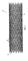
- Fig. 1 is a side view of an exemplary cylindrical vascular stent-graft having axially constant characteristics.
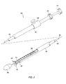
- Fig. 2 is a perspective view of an exemplary delivery catheter for use with the prostheses of the present invention, with a portion of the distal end broken away to disclose a prostheses therein.
- Fig. 3 illustrates a modular branching endoluminal prosthesis assembled from expansible prosthetic modules.
- Fig. 4 is a schematic illustration of a method for selectively expanding an integral prosthetic sealing cuff.
- FIGs. 1 to 4 represent background art illustrating a possible use of the invention and do not form part of the invention as shown.
- Figs. 5 A-C illustrate orientation indicating stent-grafts having a liner that supports marker elements, the marker elements comprising imagable bodies which define a pattern that facilitates orienting and assembling the prostheses in situ when the prosthesis is imaged fluoroscopically within a body lumen.
- Figs. 6, 7, 7A and 8 illustrate a preferred radiopaque marker element comprising an imagable body in the form of a plate having a passage to facilitate attachment of the plate to the liner.
- Fig. 9 illustrates an alternative pattern of radiopaque marker elements to facilitate orientation and assembly of an endoluminal prosthesis.
- Figs. 10 A and B illustrate a still further alternative pattern of marker elements comprising wires having loops to facilitate stitching the marker elements to the liner.
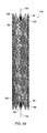
- Fig. 11 illustrates an orientation indicating endoluminal prosthesis in small diameter configuration disposed within a delivery catheter, and shows a liner supported marker element which does not interfere with the expansion or compression of the prosthesis.
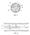
- Fig. 12 illustrates a method for radially orienting an endoluminal prosthesis by aligning a marker element of the prosthesis with a guidewire passing through the prosthesis while the prosthesis is disposed within the delivery catheter.
- Figs. 13 A and B illustrate a method for deploying a bifurcating prosthesis which includes verifying the orientation of a branch port with port orientation indicating markers while the branch port remains compressed within the delivery catheter, and by advancing a secondary prosthesis through a gate at the expanded port, the gate defined by marker elements on either side of the port centerline.
- Figs. 14 A and B illustrate a method for deploying an endoluminal prosthesis by first placing a marker band, and by then deploying an end of the prosthesis adjacent the marker band.
- Fig. 15 illustrates a method for deploying an endoluminal prosthesis similar to the method illustrated in Figs. 14 A and B, in which a conformal sponge-like sealing gasket is deployed with two marker bands to clearly mark a target region and to seal between the end of the prosthesis and an irregular surrounding body lumen.
- Figs. 16 A-D illustrate barbed endoluminal imagable bodies and a method for their use to mark the target location for an endoluminal prosthesis, according to the principles of the present invention.
- the present invention provides radially expansible tubular prostheses, particularly grafts, stents, and stent-grafts, which generally include discrete, liner supported marker elements that provide a high-contrast image when viewed under fluoroscopy, ultrasound, or some other surgical imaging modality, so as to facilitate the proper positioning of the prosthesis within a body lumen.
- the prostheses of the present invention are suitable for a wide variety of therapeutic uses, including stenting of the ureter, urethra, trachea, branchi, esophagus, biliary tract, and the like.
- the present devices and methods will also be useful for the creating of temporary or long term lumens, such as the formation of fistulas.
- the prosthetic structures of the present invention will find their most immediate use as endovascular prostheses for the treatment of diseases of the vasculature, particularly aneurysms, stenoses, and the like, and are especially well suited for therapies to treat abdominal aortic aneurysms adjacent the aortal/iliac junction.
- These prostheses will generally be radially expansible from a narrow diameter configuration to facilitate introduction into the body lumen, typically during surgical cutdown or percutaneous introduction procedures.
- prosthetic structures described hereinbelow will find use in axially uniform cylindrical prostheses, in preassembled bifurcated prostheses, and as prosthetic modules which are suitable for selective assembly either prior to deployment, or in situ.
- Such selective assembly of prosthetic modules to form a customized endoluminal prosthesis is more fully described in WO-A 9 712 562, published after the priority date.
- Prostheses 10 comprises a perforate tubular frame 12 which includes a plurality of independent (non-connected) ring frames 14.
- the tubular frame 12 supports an inner liner 18.
- an outer liner is disposed over the ring frames, either inside of inner liner 18, or in combination therewith.
- the liner is typically sutured to the frame.
- a wide variety of alternative liner/frame attachment mechanisms are available, including adhesive bonding, heat welding, ultrasonic welding, and the like. Where inner and outer liners are used, the ring frames may be sandwiched between the liners and held in place by attaching the liners to each other.
- the prostheses 10 will typically have a length in the range from about 20 mm to 500 mm, preferably from 50 mm to 200 mm, with a relaxed diameter in the range from about 4 mm to 45 mm, preferably being in the range from about 5 mm to 38 mm.
- an exemplary delivery catheter 30 for use with the endoluminal prostheses of the present invention comprises a tubular cover 32 and a shaft 34.
- Cover 32 has a central lumen 36 extending from a proximal end 38 to a distal end 40.
- Shaft 34 is slidably received within central lumen 36 and extends proximally of cover 32.
- a plurality of runners 42 extend distally from shaft 34.
- Runners 42 line a portion of the inner surface of lumen 36, and slide within the lumen of the shaft.
- Shaft 34 also has a lumen, in which a core shaft 44 is slidably disposed.
- Core shaft 44 has a guide wire lumen 46.
- Nosecone 48 is fixed to the distal end of core shaft 44, and can therefore be manipulated independently of runners 42.
- Prostheses 10 is radially compressed and restrained within the plurality of runners 42.
- cover 32 prevents runners 42 from expanding outward.
- Runners 42 are formed from a hard material, and distribute the expansion load of prostheses 10 over the inner surface of central lumen 36.
- the deploying force is applied proximally against a slider 50 attached to a distal end 38 of cover 30, while holding a luer fitting 52 at the distal end of shaft 34, thereby withdrawing the cover proximally from over the prostheses.
- An additional luer adapter 54 at the distal end of core shaft 44 allows the core shaft to be manipulated independently, and to be releasibly secured to the shaft 34.
- a branching endoluminal stent-graft 60 is assembled from prosthetic modules selected to match the needs of the diseased vascular system of the patient.
- a common lumen cuffed prosthetic module 62 seals and anchors the assembled prosthesis in the body lumen, typically within the abdominal aorta below the renal arteries and above the left and right iliac arteries.
- Y-connector module 64 engages cuffed common lumen module 62, and separates the blood flow for the iliac arteries.
- First angled branching prosthetic module 66 and second angled branching prosthetic module 68 engage the branch lumens of Y-connector module 64 to direct the luminal flow along first and second branching body lumens.
- branching prosthesis 60 allows individual tailoring of the common lumen, first branch lumen, and second branch lumen to match the geometry of the body lumen system. For example, a maximum perimeter of common lumen cuffed module 62 may be selected independently of the branching lumen perimeter limits.
- the orientation indication markers of the prostheses of the present invention are particularly advantageous for use with the radially expansible prosthesis shown schematically in Fig. 4.
- An expansible prosthesis 70 has frame rings 72 sutured to an expansible liner 74.
- Expansible liner 74 is formed from a material which expands plastically when subjected to a stress beyond a yield strength, and which remains expanded when the stress is removed, ideally exhibiting little or no spring back.
- Suitable expansible liner materials include partially oriented polyester fibers, PTFE, or inexpansible fibers wrapped around an expansible fiber, a frangible fiber, or a dissolvable fiber, and the like.
- expansible prosthesis 70 may be performed prior to shipping the prosthesis as a production step, at the surgical site prior to introduction of the prosthesis within the patient body, or preferably, after deployment of the prosthesis within a body lumen using an angioplasty-type balloon catheter or other minimally invasive expansion device.
- Frame rings 72 of expansible prosthesis 70 may comprise a material which is resilient, malleable, or some combination of the two. When resilient, frame rings 72 will preferably be radially restrained by expansible liner 74, even after expansion of the liner to the predetermined limit. Such a liner-restrained stent-graft structure avoids any loosening of the liner after balloon 78 has been removed.
- the cuff 76 of expansible prosthesis 70 often expands only to a predetermined limit, at which an element of either the liner 74 or the frame rings 72, or in some embodiments, the interface between the two, impedes further expansion.
- an orientation indicating bifurcated prosthesis 80 includes a plurality of discrete marker elements 82 which form an orientation indicating pattern 84 when imaged using fluoroscopy, ultrasound, or other imaging modalities.
- Such bifurcated prostheses will be particularly useful for reinforcing abdominal aortic aneurysms which extend into one or both iliac arteries, and will typically be used in combination with a secondary prosthetic module engaging port 85 to seal the port to the body lumen system.
- pattern 84 preferably indicates the axial location of the ends, and the axial and radial orientation of port 85, when the prosthesis is in a radially compressed configuration within a delivery catheter, and after deployment to assist deploying the secondary prosthesis within port 85.
- marker elements 82 have the least possible volume to avoid increases in the delivery catheter cross-section. Furthermore, marker elements should not interfere with the radial expansion of the prosthesis from the radially compressed configuration to the radially expanded configuration, during which perforations 86 of frame 88 expand substantially. On the other hand, the pattern should provide a sharp image, despite the fact that frame 88 will often at least partially obscure the pattern when the prosthesis is imaged.
- marker elements 82 are preferably aligned with perforations 86, ideally being substantially disposed within the perforations to maximize their image contrast against the generally radiographically clear liner 90.
- supporting the marker elements with the liner rather than attaching them directly to the frame, also helps avoid interference between the marker elements and the expansion of the surrounding frame structure. Additionally, supporting the marker elements on the liner so that they are separated from the frame will help to avoid erosion of the frame, as the marker elements will not rub against the frame with physiological movement.
- Pattern 84 defined by marker elements 82 includes several novel features.
- a port orientation indicator 92 is preferably disposed adjacent an end of the prosthesis which will be expanded before the port, and helps to verify that the orientation of port 85 will be aligned properly with the intended branching body lumen before the port is expanded in position. Fine rotational alignment of the prosthesis is facilitated by including roughly opposed marker elements 94, so that the preferred radial orientation of the prosthesis can be provided by orienting the imaging mechanism relative to the body lumen system.
- a still further feature of pattern 84 is the two axially separated gates 96 adjacent port 85.
- the axial positions and separation of these gates gives a visual indicator of the allowable prosthetic module overlap when the prosthesis is deployed and imaged in situ .
- Modular prostheses having less than a predetermined overlap may not be adequately fixed together, while branches which extend too far into the bifurcated prosthesis may lead to imbalanced flow between the branches, or may even fold over and substantially block the lumenal flow to one or both branches.
- an overlap is acceptable when an end (or an associated overlap marker) of a secondary prosthesis is disposed between the gates.
- the gates are defined by markers on either side of the port centerline, greatly improving the visibility of the markers when the delivery catheter of a secondary prosthesis enters the port.
- a pattern including such gates provides a clear demarkation of the target path between the markers when advancing a guidewire and/or a delivery catheter into the port 85 of bifurcated prosthesis 80.
- branch secondary prosthetic module 100 and trunk secondary prosthetic module 102 also include image markers 82 which define patterns to facilitate axially positioning and radially orienting these modules within a body lumen, particularly with reference to bifurcated prosthesis 80 described above.
- Each of branch module 100 and trunk module 102 include marker elements 106 which produce an image which is aligned along a prosthetic centerline 104 when the prosthesis is properly positioned relative to the imaging apparatus.
- marker elements 106 may be aligned with a guidewire passing through the prosthetic lumen even if no other rotational alignment marker is provided, thereby minimizing the total number of markers.
- Asymmetric marker elements 108 are radially offset from the centerline markers, preferably defining a radial angle between about 15° and 70° with centerline markers 106, to ensure that the modules are not 180° out of rotational alignment, which could be problematic if the modules have a preferred bend angle or some other asymmetric structure.
- a roughly 30° radial angle is preferred, as flat thin marker elements will produce smaller images when viewed edge-on that tend to blend into the frame as the angle approaches 90°, while smaller angles will be difficult to differentiate. Furthermore, such significantly off-centerline markers are less likely to be overshadowed by subsequent guidewire or delivery catheter placements. Left and right off-centerline markers may be included to ensure the prosthesis is not roughly 150° out of rotational alignment.
- the asymmetric marker elements can also easily be aligned with the port indicator markers 92 or otherwise consistently aligned with some other imagable structure of the bifurcated prosthesis of Fig. 5 A.
- the prostheses of the present invention will often include different materials for the frame and for the marker elements.
- the frame material will often comprise a high strength metal
- the marker elements will generally comprise a radiopaque metal or a metal which produces an enhanced ultrasound image.
- EMF Electromotive Force
- the present invention provides endoluminal prostheses with frames and marker element having similar EMF characteristics.
- a particularly preferred combination combines frames which include Nitinol and marker elements which include tantalum. These materials exhibit excellent strength and imagability, respectively, and are of sufficiently similar characteristics to avoid electrolytic corrosion.
- the radiopaque particles comprise tantalum, the particles ideally being between about 1 and 5 microns, and are continuously blended with the compound before application to the liner.
- a suitable polyester matrix may comprise a polyester such as DacronTM, while the solvent may include hexofluoro 2-propanol, methylene chloride, a combination of both, or the like.
- a preferred marker element structure comprising an imagable body attached to the liner will be described with reference to Figs. 6,7,7A and 8.
- the imagable body here comprises a plate 130 stitched to liner 132 with sutures 134.
- Plate 130 includes two passages 136 to facilitate attachment, and will generally comprise a material which provides a high contrast when imaged, typically including a radiopaque material such as gold, platinum, or other implantable metals.
- plate 130 comprises tantalum having a thickness of at least about 0.0508mm (.002 inches), preferably being about 0.25mm (.01 inches).
- Such tantalum plates may be mass produced by die cutting or laser cutting sheet stock, preferably leaving a chain of plates 135 attached by detachable tabs 138 and ready for use.
- the edges of plates 130 will be rounded to avoid any injury to adjacent tissues, and to avoid cutting any liner or attachment fibers.
- the plates will often be sewn to the outer surface of the liner material to avoid interference with the vascular flow or the generation of thrombus.
- the prosthetic lumen remains uninterrupted.
- the plates are generally attached along a radius of the liner, they should not substantially interfere with expansion of the liner material.
- expansible sutures such as a partially oriented polyester yarn may be used to attach the plates.
- the imagable bodies of the present invention could comprise a variety of alternative shapes and liner attachment mechanisms. Snaps, rivets, staples, and the like could attach through the liner, or knobs or other shapes could be sewn, adhesively bonded, or otherwise affixed to the liner within the scope of the present invention. Plates 130 having at least one passage 136 are generally preferred, however, as they provide a relatively large image, do not substantially distort or interrupt the prosthetic lumen, and can be very securely attached to the liner.
- FIG. 9 An alternative orientation indicating pattern which can also be used for the endoluminal prosthesis of the present invention having an external frame, is illustrated in Fig. 9, the pattern including opposed marker elements 142 which axially overlap when the prosthesis is rotationally aligned relative to the imaging system. Additionally, the port orientation is here indicated by alternating front port orientation markers 144 and rear port orientation markers 146. When these alternating port markers are lined up and evenly spaced, the prosthesis is aligned and the port is on the side of the prosthesis toward which the line of port orientation markers slant.
- FIG. 10 A and B A still further marker element and pattern are illustrated in Figs. 10 A and B.
- Pattern 150 is defined by the images of wires 152 having loops 154 for attachment to the liner.
- the contrast of the wires may be enhanced by windings 156, the wires and windings comprising a high contrast material, often including gold, platinum, tantalum, or the like.
- a single gate 96 formed with such wire marker elements may indicate an axial overlap range by careful selection of the length of the wires.
- one advantage of the liner supported marker elements of the present invention is that the marker element can fold out of the way of the frame with the liner. Ring frame 14 can be tightly compressed within sheath 32, leaving little space between the frame arms.
- a guidewire 134 may be used to radially align a prosthesis prior to deployment by rotating the catheter within a body lumen L to align an image of the guidewire with an image of a marker element. Hence, only a single marker element may be required for radial orientation.
- FIGs. 13 A and B A method of deploying branching prosthesis 80 and branch module 100 for treatment of an abdominal aortic aneurysm AAA is illustrated in Figs. 13 A and B.
- Aneurysm AAA extends along the aortic artery A from below the renal arteries R and onto the iliacs I.
- the imaging system is typically oriented toward the plane of the aorta/iliac bifurcation.
- the catheter is introduced and axially positioned under fluoroscopy so that the prosthesis extends along the weakened aorta and into one of the iliacs.
- the port indicator marker elements 92 By rotating the catheter until the port indicator marker elements 92 are generally on the side of the opposite iliac, the port can be generally oriented to accept branch module 100. Further alignment can be provided by aligning axially offset opposed markers 94.
- the distal end of the prosthesis is deployed.
- this provides a clear view of port orientation indicating marker elements 92 well before the port itself is expanded. If further rotational adjustment is necessary, it may be possibly to simply rotate the expanded prosthesis end against the healthy tissue beyond the aneurysm. Alternatively, the expanded end may be withdrawn into the catheter and repositioned or replaced much easier than if the sheath is withdrawn beyond the port itself.
- the port orientation indicating markers may instead be disposed adjacent the prosthetic branch end within the iliac to provide similar benefits.
- the gates 96 adjacent the port on prosthesis 80 clearly indicate the path of the port axis to facilitate introduction of guidewire 134 and the delivery catheter for the branch module.
- the marker elements which define the gate can remain visible even when the delivery catheter is disposed in the port. This significantly eases positioning marker elements 82 adjacent the end of the branch module axially between gates 96, thereby assuring that the prosthetic overlap is within the predetermined allowable range.
- a body lumen marker comprising a helical marker band 140 may be deployed with a catheter 142 to mark the specific target location for an end of the branching prosthesis 80.
- the marker band delivery catheter 142 may incorporate intravascular ultrasound (IVUS) imaging capabilities to more accurately determine the extent of aneurysm AAA than is possible using fluoroscopy alone.
- IVUS intravascular ultrasound
- the deployed marker band 140 thereafter clearly marks the location for a subsequent fluoroscopically directed endoluminal prosthesis deployment (as shown in Fig. 14 B), the marker band generally comprising a radiopaque material.
- a sealing gasket material is deployed with marker band 140 to seal between the later-deployed prosthesis and the surrounding body lumen, as shown in Fig. 15.
- a sealing gasket preferably comprises a sponge-like silicone or other polymer.
- two or more marker bands 140 may be deployed with each gasket to indicate a range of allowable axial positions, and optionally to help affix the gasket in position.
- Such marked sealing gaskets may be provided at each end of the prosthesis to fully seal the prosthetic lumen to the body lumen system.
- Marker bands 140 may comprise resilient or plastically expansible materials, but will preferably have an axial length of less than about 2 cm, ideally less than about 1 cm, to accurately mark a specific axial position.
- FIG. 16 A-D Alternative endoluminal body lumen markers are illustrated in Figs. 16 A-D.
- these endoluminal markers 150 comprise imagable bodies 152 which are held in position by barbed protrusions 154 which penetrate at least partially into the lumenal wall W.
- the tubular endoluminal prosthesis may be positioned over the body lumen markers, thereby helping to hold them in position against the body lumen wall.
- the body lumen markers may include hooks 156 or other prosthesis engaging structures opposite the barbed protrusion 154 to maintain the position of the subsequently deployed prosthesis within the body lumen.
- the body lumen markers will typically comprise a radiographic material such as tantalum, gold, platinum, or the like, and may be deployed using a high torque, high control delivery catheter, a balloon catheter, or the like.
- the marker bands 140 and endoluminal markers 150 may also find use in measuring or verifying the actual diameter of the vessel prior to prosthesis. Such independent marker elements which engage the lumenal wall will also be useful in follow-up procedures to determine whether the prosthesis has migrated, whether there has been any change in length or diameter of the aneurysm or the prosthesis over time.
Abstract
Description
- The present invention relates to an endoluminal prosthesis according to the preamble of claim 1, an endoluminal prosthesis system according to claim 16 and a method for fabricating a position indicating endoluminal prosthesis according to the preamble of claim 17.
- The present invention thus relates generally to tubular prostheses, such as grafts, stents, stent-grafts, and the like. More particularly, the present invention provides endoluminal prostheses having discrete position indicating elements which facilitate orienting and deploying the prostheses within body lumens, particularly within branching blood vessels for the treatment of abdominal and other aneurysms.
- Vascular aneurysms are the result of abnormal dilation of a blood vessel, usually resulting from disease and/or genetic predisposition, which can weaken the arterial wall and allow it to expand. While aneurysms can occur in any blood vessel, most occur in the aorta and peripheral arteries, with the majority of aortic aneurysms occurring in the abdominal aorta, usually beginning below the renal arteries and often extending into one or both of the iliac arteries.
- Aortic aneurysms are most commonly treated in open surgical procedures, where the diseased vessel segment is bypassed and repaired with an artificial vascular graft. While considered to be an effective surgical technique, particularly considering the alternative of a usually fatal ruptured abdominal aortic aneurysm, conventional vascular graft surgery suffers from a number of disadvantages. The surgical procedure is complex and requires experienced surgeons and well equipped surgical facilities. Even with the best surgeons and equipment, however, patients being treated frequently are elderly and weakened from cardiovascular and other diseases, reducing the number of eligible patients. Even for eligible patients prior to rupture, conventional aneurysm repair has a relatively high morality rate, usually from 2% to 10%. Morbidity related to the conventional surgery includes myocardial infarction, renal failure, impotence, paralysis, and other conditions. Additionally, even with successful surgery, recovery takes several weeks, and often requires a lengthy hospital stay.
- In order to overcome some or all of these drawbacks, endovascular prosthesis placement for the treatment of aneurysms has been proposed. Although very promising, many of the proposed methods and apparatus suffer from undesirable limitations. In particular, proper positioning of an endovascular prosthesis within the vascular system can be problematic.
- Accurately positioning and orienting endoluminal prostheses is critical to the efficacy of endovascular aneurysm therapies. These tubular prostheses are generally introduced into the vascular system within a catheter and in a radially compressed configuration, typically being maneuvered into position under fluoroscopy. The positioned prosthesis will radially expand, preferably engaging and sealing against the endolithium of the healthy vessel wall both upstream and downstream of the weakened, distended aneurysm. The prosthesis may expand resiliently when released from the catheter, or may be mechanically expanded, typically using a balloon catheter. In either case, the prosthesis will preferably span the entire aneurysm to prevent pressure from acting on the weakened lumenal wall, and to prevent leakage through any rupture of the aneurysm. To provide these advantages, the prosthesis must be axial positioned accurately across the aneurysm so as to isolate it from the blood flow through the prosthetic lumen.
- Proper radial orientation of endoluminal prostheses is also important, particularly when deploying branching and asymmetric prostheses within the tortuous vascular system. If the branches of branching prostheses are not oriented toward their respective branching body lumens, the surrounding body lumen may be distended to adapt to the misaligned prosthesis, or the prosthetic lumen may be distorted or even closed entirely. For example, if the trunk of a bifurcated prosthesis is deployed with a branch oriented 90° from the iliac arteries (i.e., angling dorsally rather than laterally), the prosthetic branch lumen may fold or kink, and will have to at least bend at a sharp angle to enter the laterally oriented iliac. In fact, as branching prostheses are often assembled in situ, it may not be possible to introduce the branch prosthesis into such a misaligned branch port. As recapture or repositioning of expanded endoluminal prostheses is often problematic, it may even be necessary to resort to an emergency invasive procedure to remedy such misalignment.
- Tubular endovascular prostheses are often formed as stent-grafts having a flexible tubular liner or "graft" which is supported by a perforate tubular frame or "stent". The frame perforations define radially expandable structures, while the frame often include metals which are, to some extent, visible under fluoroscopy.
- To facilitate positioning of endovascular prostheses, it has previously been proposed to coil gold or platinum wires around an element of the perforate frame structure to enhance the visibility of the prosthesis under fluoroscopy. Similarly, it has been suggested that a tube be crimped over an element of the frame. Unfortunately, affixing such structures to the frame may limit or interfere with the radial compressibility of the prosthesis. It can also be difficult to identify the portion of the frame having an enhanced image against the backdrop of the frame itself, and to orient the prosthesis properly based on one or more enhanced frame arms.
- Alternatively, it has been suggested to affix radiopaque lines or image markers to bifurcated grafts in the form of fine wire or chain, either woven into the cloth or applied after weaving, or as an inert paint or plastic. However, the liners of endoluminal prostheses must remain highly flexible, typically being folded when the prosthesis is compressed and unfolding during deployment. Wires, chains, or paints which are sufficiently flexible will generally provide only limited-contrast images when the graft is supported by the obscuring frame, and may become detached from the prosthesis once deployed in the body lumen, with potentially catastrophic consequences. Moreover, imaging of such thin, flexible, low-contrast markers is particularly difficult when the prosthesis is in the high density, radially compressed configuration and disposed within a catheter, as is generally required for intravascular maneuvering.
- For these reasons, it would be desirable to provide improved endoluminal prostheses and methods for their use. It would be particularly desirable to provide endoluminal prostheses having high-contrast orientation indicating imaging markers which do not interfere with radial compression or expansion, and which are securely and reliably attached to the prosthesis. It would further be desirable if such markers could clearly indicate both the position and orientation of the prosthesis, ideally while the prosthesis remains compressed in the delivery catheter, but without substantially increasing the size of the delivery system.
- WO 95/21,592 describes a bifurcated endoluminal prosthesis including a bifurcated stent and a second stent. One or more X-ray opaque coils or tubes may de disposed over an arm of the stent structure so that the stents can be aligned and engaged in situ under X-ray monitoring. US-A-5387235 describes a bifurcated graft having radiopaque lines and markers formed of fine wire or chains of inert metal, or of an inert paint or plastic.
- Known from EP-A-508 473, which is used as a basis for the preamble of claims 1 and 17, is an endovascular graft for deployment in a body lumen of a patient body, comprising a deformable cylindrical body woven of surgically implantable material such as Dacron-type fibre. Radiopaque markers in the form of lengths of platinum wire secured to the fabric of the graft by suitable means such as Dacron sutures are provided for indicating the position of the graft when imaged within the patient body. The body has an open end and is provided with a bifurcation or crotch at the other end which opens into first and second legs having open ends. The open ends are provided with expandable spring attachment means which are secured inside the body and which serve as anchoring means for securing the graft to a vessel wall in which the graft is disposed.
- The invention is defined in claims 1, 16 and 17.
- In one embodiment, the present invention provides an endoluminal prosthesis for deployment in a body lumen of a patient body, the prosthesis comprising a tubular fabric liner and a radially expandable frame supporting the liner. A plurality of imagable bodies are attached to the liner, the imagable bodies providing a sharp contrast so as to define a pattern which indicates the prosthesis position when the prosthesis is imaged within the patient body. Preferably, each imagable body comprises a plate having first and second opposed major surfaces and a passage therebetween to facilitate stitching the plate to the liner. Advantageously, the imagable bodies can be aligned with the openings of a perforate frame structure so that at least some of the imagable bodies are visible through associated openings, and need not actually be attached to the frame directly. Such imagable bodies are clearly visible when the prosthesis is deployed, and can also be sized to produce distinct images even when the frame is compressed within a delivery catheter, but should not interfere with the radial expansion of the frame during deployment. The imagable bodies optionally comprise a radiopaque material, or may alternatively produce enhanced ultrasound images. Preferably, the frame and the imagable bodies will have a similar electromotive force (EMF) to avoid corrosion.
- In another embodiment, the present invention provides an endoluminal prosthesis for deployment in a body lumen of a patient body, the prosthesis comprising a tubular fabric liner and a radially expandable frame supporting the liner. A plurality of radiopaque marker elements, each defining a passage therethrough, are stitched to the liner through the passage. The marker elements indicate a position of the prosthesis when the prosthesis is radiographically imaged within the body lumen. In some embodiments, the marker elements comprise plates. Alternatively, the marker elements comprise wires having a plurality of loops which define the passages.
- In yet another embodiment, the present invention provides an endoluminal prosthesis for deployment in a body lumen of a patient body, the prosthesis comprising a radially expandable tubular body defining a centerline and a plurality of radiopaque marker elements disposed on the body. The marker elements define a pattern when the prosthesis is imaged within the patient body, the pattern including a gate disposed adjacent to a distal or proximal port. The gate comprises radially separated marker elements on opposed sides of the centerline when the prosthesis is properly oriented to facilitate deployment of a secondary prosthetic module within the adjacent port of the prosthesis. Optionally, the pattern may include two axially separated gates which define an allowable prosthetic overlap region therebetween. As the marker elements which define these gates are offset on opposite sides of the centerline, they remain highly visible when the delivery catheter containing the secondary prosthetic module is being positioned within the port.
- The present invention further provides a method for fabricating a position indicating endoluminal prosthesis for use in a body lumen of a patient body. The method comprises affixing a radially expandable frame to a tubular liner so that the frame supports the liner, and attaching a plurality of marker elements to the liner so that the elements define a pattern. The marker elements are capable of producing a sharp contrast when imaged so that the pattern indicates a position of the prosthesis when the prosthesis is imaged within the patient body. Preferably, the attaching step comprises stitching through at least one opening in each marker element.
- An endoluminal prosthesis according to the present invention may be assembled at a target location of a body lumen by introducing a first tubular endoluminal prosthetic module into the body lumen and positioning the first module adjacent to the target location. The first module is radially expanded to deploy the module adjacent to the target location, the expanded first module having first and second marker elements disposed adjacent to a port. A second tubular prosthetic module is introducing into the body lumen and positioned within the port of the first module by imaging the first module and axially advancing the second module between the first and second marker elements.
- A tubular endoluminal prosthesis according to the present invention may be positioned at a target location of a body lumen by introducing a guidewire through the body lumen and advancing the guidewire beyond the target location, and advancing the prosthesis over the guidewire so that the guidewire passes through a lumen of the prosthesis. The prosthesis is radially oriented by imaging the prosthesis within the body lumen and aligning an image of a marker element of the prosthesis with an image of the guidewire.
- A tubular endoluminal prosthesis according to the present invention may also be positioned at a target location of a body lumen by introducing the prosthesis into the body lumen and positioning the prosthesis adjacent to the target location. The prosthesis is radially oriented by imaging the prosthesis within the body lumen and aligning an image of a first marker element of the prosthesis with an image of a second marker element of the prosthesis, wherein the first and second marker elements are axially offset from each other.
- The radial orientation of a port of a branching tubular endoluminal prosthesis within a body lumen may be verified by introducing the prosthesis into the body lumen and radially orienting the prosthesis. An end of the prosthesis which is separated from the port is deployed by axially withdrawing a surrounding sheath and allowing the prosthesis end to expand. At least one port orientation indicating marker element disposed on the expanded end of the prosthesis can then be imaged while the prosthesis adjacent the port remains in a compressed state, thereby clearly showing the radial orientation of the port while recompression of the prosthesis is still relatively easy.
- An endoluminal prosthesis according to the present invention may be deployed by introducing and deploying a marker element in a body lumen so as to mark a target location. The prosthesis is introduced into the body lumen and aligned with the marker element. These marker elements, which may comprise marker bands or barbed imagable bodies, are particularly useful in follow-up procedures to monitor migration of the prosthesis or changes in aneurysms or other disease conditions, which will often appear as changes in the relative positions of the marker element and the prosthesis.
- Methods for assembling, positioning, verifying the position of and deploying an endoluminal prosthesis do not form part of the invention as such.
- Fig. 1 is a side view of an exemplary cylindrical vascular stent-graft having axially constant characteristics.
- Fig. 2 is a perspective view of an exemplary delivery catheter for use with the prostheses of the present invention, with a portion of the distal end broken away to disclose a prostheses therein.
- Fig. 3 illustrates a modular branching endoluminal prosthesis assembled from expansible prosthetic modules.
- Fig. 4 is a schematic illustration of a method for selectively expanding an integral prosthetic sealing cuff.
- (Figs. 1 to 4 represent background art illustrating a possible use of the invention and do not form part of the invention as shown.)
- Figs. 5 A-C illustrate orientation indicating stent-grafts having a liner that supports marker elements, the marker elements comprising imagable bodies which define a pattern that facilitates orienting and assembling the prostheses in situ when the prosthesis is imaged fluoroscopically within a body lumen.
- Figs. 6, 7, 7A and 8 illustrate a preferred radiopaque marker element comprising an imagable body in the form of a plate having a passage to facilitate attachment of the plate to the liner.
- Fig. 9 illustrates an alternative pattern of radiopaque marker elements to facilitate orientation and assembly of an endoluminal prosthesis.
- Figs. 10 A and B illustrate a still further alternative pattern of marker elements comprising wires having loops to facilitate stitching the marker elements to the liner.
- Fig. 11 illustrates an orientation indicating endoluminal prosthesis in small diameter configuration disposed within a delivery catheter, and shows a liner supported marker element which does not interfere with the expansion or compression of the prosthesis.
- Fig. 12 illustrates a method for radially orienting an endoluminal prosthesis by aligning a marker element of the prosthesis with a guidewire passing through the prosthesis while the prosthesis is disposed within the delivery catheter.
- Figs. 13 A and B illustrate a method for deploying a bifurcating prosthesis which includes verifying the orientation of a branch port with port orientation indicating markers while the branch port remains compressed within the delivery catheter, and by advancing a secondary prosthesis through a gate at the expanded port, the gate defined by marker elements on either side of the port centerline.
- Figs. 14 A and B illustrate a method for deploying an endoluminal prosthesis by first placing a marker band, and by then deploying an end of the prosthesis adjacent the marker band.
- Fig. 15 illustrates a method for deploying an endoluminal prosthesis similar to the method illustrated in Figs. 14 A and B, in which a conformal sponge-like sealing gasket is deployed with two marker bands to clearly mark a target region and to seal between the end of the prosthesis and an irregular surrounding body lumen.
- Figs. 16 A-D illustrate barbed endoluminal imagable bodies and a method for their use to mark the target location for an endoluminal prosthesis, according to the principles of the present invention.
- The present invention provides radially expansible tubular prostheses, particularly grafts, stents, and stent-grafts, which generally include discrete, liner supported marker elements that provide a high-contrast image when viewed under fluoroscopy, ultrasound, or some other surgical imaging modality, so as to facilitate the proper positioning of the prosthesis within a body lumen. The prostheses of the present invention are suitable for a wide variety of therapeutic uses, including stenting of the ureter, urethra, trachea, branchi, esophagus, biliary tract, and the like. The present devices and methods will also be useful for the creating of temporary or long term lumens, such as the formation of fistulas.
- The prosthetic structures of the present invention will find their most immediate use as endovascular prostheses for the treatment of diseases of the vasculature, particularly aneurysms, stenoses, and the like, and are especially well suited for therapies to treat abdominal aortic aneurysms adjacent the aortal/iliac junction. These prostheses will generally be radially expansible from a narrow diameter configuration to facilitate introduction into the body lumen, typically during surgical cutdown or percutaneous introduction procedures.
- The prosthetic structures described hereinbelow will find use in axially uniform cylindrical prostheses, in preassembled bifurcated prostheses, and as prosthetic modules which are suitable for selective assembly either prior to deployment, or in situ. Such selective assembly of prosthetic modules to form a customized endoluminal prosthesis is more fully described in WO-A 9 712 562, published after the priority date.
- An exemplary
cylindrical graft structure 10 is illustrated in Fig. 1.Prostheses 10 comprises a perforatetubular frame 12 which includes a plurality of independent (non-connected) ring frames 14. Thetubular frame 12 supports aninner liner 18. Optionally, an outer liner is disposed over the ring frames, either inside ofinner liner 18, or in combination therewith. - TO secure ring frames 14 in place, and to secure the liner to the perforate
tubular frame 12, the liner is typically sutured to the frame. A wide variety of alternative liner/frame attachment mechanisms are available, including adhesive bonding, heat welding, ultrasonic welding, and the like. Where inner and outer liners are used, the ring frames may be sandwiched between the liners and held in place by attaching the liners to each other. - The
prostheses 10 will typically have a length in the range from about 20 mm to 500 mm, preferably from 50 mm to 200 mm, with a relaxed diameter in the range from about 4 mm to 45 mm, preferably being in the range from about 5 mm to 38 mm. - Referring now to Fig. 2, an
exemplary delivery catheter 30 for use with the endoluminal prostheses of the present invention comprises atubular cover 32 and ashaft 34.Cover 32 has acentral lumen 36 extending from aproximal end 38 to adistal end 40.Shaft 34 is slidably received withincentral lumen 36 and extends proximally ofcover 32. A plurality ofrunners 42 extend distally fromshaft 34.Runners 42 line a portion of the inner surface oflumen 36, and slide within the lumen of the shaft.Shaft 34 also has a lumen, in which acore shaft 44 is slidably disposed.Core shaft 44 has aguide wire lumen 46.Nosecone 48 is fixed to the distal end ofcore shaft 44, and can therefore be manipulated independently ofrunners 42. -
Prostheses 10 is radially compressed and restrained within the plurality ofrunners 42. In turn, cover 32 preventsrunners 42 from expanding outward.Runners 42 are formed from a hard material, and distribute the expansion load ofprostheses 10 over the inner surface ofcentral lumen 36. The deploying force is applied proximally against aslider 50 attached to adistal end 38 ofcover 30, while holding a luer fitting 52 at the distal end ofshaft 34, thereby withdrawing the cover proximally from over the prostheses. Anadditional luer adapter 54 at the distal end ofcore shaft 44 allows the core shaft to be manipulated independently, and to be releasibly secured to theshaft 34. - Although the structures of the present invention will at times be described with reference to simple tubular prostheses having a single lumen, it should be understood that the present invention also generally encompasses more complex branching and modular endoluminal prostheses. Referring to Fig. 3, for example, a branching endoluminal stent-
graft 60 is assembled from prosthetic modules selected to match the needs of the diseased vascular system of the patient. A common lumen cuffedprosthetic module 62 seals and anchors the assembled prosthesis in the body lumen, typically within the abdominal aorta below the renal arteries and above the left and right iliac arteries. Y-connector module 64 engages cuffedcommon lumen module 62, and separates the blood flow for the iliac arteries. First angled branchingprosthetic module 66 and second angled branchingprosthetic module 68 engage the branch lumens of Y-connector module 64 to direct the luminal flow along first and second branching body lumens. - The modular construction and expansible structure of branching
prosthesis 60 allows individual tailoring of the common lumen, first branch lumen, and second branch lumen to match the geometry of the body lumen system. For example, a maximum perimeter of common lumen cuffedmodule 62 may be selected independently of the branching lumen perimeter limits. - The orientation indication markers of the prostheses of the present invention are particularly advantageous for use with the radially expansible prosthesis shown schematically in Fig. 4. An
expansible prosthesis 70 has frame rings 72 sutured to anexpansible liner 74.Expansible liner 74 is formed from a material which expands plastically when subjected to a stress beyond a yield strength, and which remains expanded when the stress is removed, ideally exhibiting little or no spring back. Suitable expansible liner materials include partially oriented polyester fibers, PTFE, or inexpansible fibers wrapped around an expansible fiber, a frangible fiber, or a dissolvable fiber, and the like. By subjecting acuff 76 to the expansive force ofballoon 78, the liner perimeter at a selected cross-section is increased. Advantageously, the expansion ofexpansible prosthesis 70 may be performed prior to shipping the prosthesis as a production step, at the surgical site prior to introduction of the prosthesis within the patient body, or preferably, after deployment of the prosthesis within a body lumen using an angioplasty-type balloon catheter or other minimally invasive expansion device. - Frame rings 72 of
expansible prosthesis 70 may comprise a material which is resilient, malleable, or some combination of the two. When resilient, frame rings 72 will preferably be radially restrained byexpansible liner 74, even after expansion of the liner to the predetermined limit. Such a liner-restrained stent-graft structure avoids any loosening of the liner afterballoon 78 has been removed. Thecuff 76 ofexpansible prosthesis 70 often expands only to a predetermined limit, at which an element of either theliner 74 or the frame rings 72, or in some embodiments, the interface between the two, impedes further expansion. - Referring now to Fig. 5 A, an orientation indicating
bifurcated prosthesis 80 includes a plurality ofdiscrete marker elements 82 which form anorientation indicating pattern 84 when imaged using fluoroscopy, ultrasound, or other imaging modalities. Such bifurcated prostheses will be particularly useful for reinforcing abdominal aortic aneurysms which extend into one or both iliac arteries, and will typically be used in combination with a secondary prostheticmodule engaging port 85 to seal the port to the body lumen system. Toward that end,pattern 84 preferably indicates the axial location of the ends, and the axial and radial orientation ofport 85, when the prosthesis is in a radially compressed configuration within a delivery catheter, and after deployment to assist deploying the secondary prosthesis withinport 85. - Minimizing the radial dimensions of the prosthesis significantly facilitates the intravascular maneuvering of the prosthesis during positioning and deployment. Therefore, it is generally desirable that
marker elements 82 have the least possible volume to avoid increases in the delivery catheter cross-section. Furthermore, marker elements should not interfere with the radial expansion of the prosthesis from the radially compressed configuration to the radially expanded configuration, during which perforations 86 offrame 88 expand substantially. On the other hand, the pattern should provide a sharp image, despite the fact thatframe 88 will often at least partially obscure the pattern when the prosthesis is imaged. - For the above reasons,
marker elements 82 are preferably aligned withperforations 86, ideally being substantially disposed within the perforations to maximize their image contrast against the generally radiographicallyclear liner 90. Generally, supporting the marker elements with the liner, rather than attaching them directly to the frame, also helps avoid interference between the marker elements and the expansion of the surrounding frame structure. Additionally, supporting the marker elements on the liner so that they are separated from the frame will help to avoid erosion of the frame, as the marker elements will not rub against the frame with physiological movement. -
Pattern 84 defined bymarker elements 82 includes several novel features. Aport orientation indicator 92 is preferably disposed adjacent an end of the prosthesis which will be expanded before the port, and helps to verify that the orientation ofport 85 will be aligned properly with the intended branching body lumen before the port is expanded in position. Fine rotational alignment of the prosthesis is facilitated by including roughly opposedmarker elements 94, so that the preferred radial orientation of the prosthesis can be provided by orienting the imaging mechanism relative to the body lumen system. Surprisingly, in work done in connection with the present invention, such radial alignment has been found to be improved by axially offsetting opposed marker elements, so that the elements do not partially block each other's image during alignment, and to help distinguish a "front" marker element from a "back" marker element. - A still further feature of
pattern 84 is the two axially separatedgates 96adjacent port 85. The axial positions and separation of these gates gives a visual indicator of the allowable prosthetic module overlap when the prosthesis is deployed and imaged in situ. Modular prostheses having less than a predetermined overlap may not be adequately fixed together, while branches which extend too far into the bifurcated prosthesis may lead to imbalanced flow between the branches, or may even fold over and substantially block the lumenal flow to one or both branches. - Generally, an overlap is acceptable when an end (or an associated overlap marker) of a secondary prosthesis is disposed between the gates. Advantageously, the gates are defined by markers on either side of the port centerline, greatly improving the visibility of the markers when the delivery catheter of a secondary prosthesis enters the port. Furthermore, a pattern including such gates provides a clear demarkation of the target path between the markers when advancing a guidewire and/or a delivery catheter into the
port 85 ofbifurcated prosthesis 80. - Referring now to Figs. 5 B and C, branch secondary
prosthetic module 100 and trunk secondaryprosthetic module 102 also includeimage markers 82 which define patterns to facilitate axially positioning and radially orienting these modules within a body lumen, particularly with reference to bifurcatedprosthesis 80 described above. - Each of
branch module 100 andtrunk module 102 includemarker elements 106 which produce an image which is aligned along aprosthetic centerline 104 when the prosthesis is properly positioned relative to the imaging apparatus. Advantageously, such a marker element may be aligned with a guidewire passing through the prosthetic lumen even if no other rotational alignment marker is provided, thereby minimizing the total number of markers.Asymmetric marker elements 108 are radially offset from the centerline markers, preferably defining a radial angle between about 15° and 70° withcenterline markers 106, to ensure that the modules are not 180° out of rotational alignment, which could be problematic if the modules have a preferred bend angle or some other asymmetric structure. A roughly 30° radial angle is preferred, as flat thin marker elements will produce smaller images when viewed edge-on that tend to blend into the frame as the angle approaches 90°, while smaller angles will be difficult to differentiate. Furthermore, such significantly off-centerline markers are less likely to be overshadowed by subsequent guidewire or delivery catheter placements. Left and right off-centerline markers may be included to ensure the prosthesis is not roughly 150° out of rotational alignment. The asymmetric marker elements can also easily be aligned with theport indicator markers 92 or otherwise consistently aligned with some other imagable structure of the bifurcated prosthesis of Fig. 5 A. - Regardless of the specific radiopaque marker structure selected, the prostheses of the present invention will often include different materials for the frame and for the marker elements. As described above, the frame material will often comprise a high strength metal, while the marker elements will generally comprise a radiopaque metal or a metal which produces an enhanced ultrasound image. One potential problem with known endoluminal prostheses having such dissimilar metals is that a substantial difference in Electromotive Force (EMF) of adjacent metallic materials may promote corrosion. To avoid this problem, the present invention provides endoluminal prostheses with frames and marker element having similar EMF characteristics. A particularly preferred combination combines frames which include Nitinol and marker elements which include tantalum. These materials exhibit excellent strength and imagability, respectively, and are of sufficiently similar characteristics to avoid electrolytic corrosion.
- Preferably, the radiopaque particles comprise tantalum, the particles ideally being between about 1 and 5 microns, and are continuously blended with the compound before application to the liner. A suitable polyester matrix may comprise a polyester such as Dacron™, while the solvent may include hexofluoro 2-propanol, methylene chloride, a combination of both, or the like. In some embodiments, it may be advantageous to pre-wet the polyester liner prior to applying the compound with a polyester solvent, typically comprising a diluted version of the solvent used in the radiopaque compound.
- A preferred marker element structure comprising an imagable body attached to the liner will be described with reference to Figs. 6,7,7A and 8. The imagable body here comprises a
plate 130 stitched toliner 132 withsutures 134.Plate 130 includes twopassages 136 to facilitate attachment, and will generally comprise a material which provides a high contrast when imaged, typically including a radiopaque material such as gold, platinum, or other implantable metals. Ideally,plate 130 comprises tantalum having a thickness of at least about 0.0508mm (.002 inches), preferably being about 0.25mm (.01 inches). Such tantalum plates may be mass produced by die cutting or laser cutting sheet stock, preferably leaving a chain ofplates 135 attached bydetachable tabs 138 and ready for use. In most embodiments, the edges ofplates 130 will be rounded to avoid any injury to adjacent tissues, and to avoid cutting any liner or attachment fibers. - The plates will often be sewn to the outer surface of the liner material to avoid interference with the vascular flow or the generation of thrombus. Advantageously, since the liner is also supported by an
external frame 140, the prosthetic lumen remains uninterrupted. Furthermore, where the plates are generally attached along a radius of the liner, they should not substantially interfere with expansion of the liner material. Optionally, expansible sutures (such as a partially oriented polyester yarn) may be used to attach the plates. - The imagable bodies of the present invention could comprise a variety of alternative shapes and liner attachment mechanisms. Snaps, rivets, staples, and the like could attach through the liner, or knobs or other shapes could be sewn, adhesively bonded, or otherwise affixed to the liner within the scope of the present invention.
Plates 130 having at least onepassage 136 are generally preferred, however, as they provide a relatively large image, do not substantially distort or interrupt the prosthetic lumen, and can be very securely attached to the liner. - An alternative orientation indicating pattern which can also be used for the endoluminal prosthesis of the present invention having an external frame, is illustrated in Fig. 9, the pattern including opposed
marker elements 142 which axially overlap when the prosthesis is rotationally aligned relative to the imaging system. Additionally, the port orientation is here indicated by alternating frontport orientation markers 144 and rearport orientation markers 146. When these alternating port markers are lined up and evenly spaced, the prosthesis is aligned and the port is on the side of the prosthesis toward which the line of port orientation markers slant. - A still further marker element and pattern are illustrated in Figs. 10 A and
B. Pattern 150 is defined by the images ofwires 152 havingloops 154 for attachment to the liner. Optionally, the contrast of the wires may be enhanced bywindings 156, the wires and windings comprising a high contrast material, often including gold, platinum, tantalum, or the like. Advantageously, asingle gate 96 formed with such wire marker elements may indicate an axial overlap range by careful selection of the length of the wires. - Referring now to Fig. 11, one advantage of the liner supported marker elements of the present invention is that the marker element can fold out of the way of the frame with the liner.
Ring frame 14 can be tightly compressed withinsheath 32, leaving little space between the frame arms. - Referring now to both Figs. 11 and 12, a
guidewire 134 may be used to radially align a prosthesis prior to deployment by rotating the catheter within a body lumen L to align an image of the guidewire with an image of a marker element. Hence, only a single marker element may be required for radial orientation. - A method of deploying branching
prosthesis 80 andbranch module 100 for treatment of an abdominal aortic aneurysm AAA is illustrated in Figs. 13 A and B. Aneurysm AAA extends along the aortic artery A from below the renal arteries R and onto the iliacs I. The imaging system is typically oriented toward the plane of the aorta/iliac bifurcation. The catheter is introduced and axially positioned under fluoroscopy so that the prosthesis extends along the weakened aorta and into one of the iliacs. By rotating the catheter until the portindicator marker elements 92 are generally on the side of the opposite iliac, the port can be generally oriented to acceptbranch module 100. Further alignment can be provided by aligning axially offset opposedmarkers 94. - Once the prosthesis appears to be properly positioned and aligned, the distal end of the prosthesis is deployed. Advantageously, this provides a clear view of port orientation indicating
marker elements 92 well before the port itself is expanded. If further rotational adjustment is necessary, it may be possibly to simply rotate the expanded prosthesis end against the healthy tissue beyond the aneurysm. Alternatively, the expanded end may be withdrawn into the catheter and repositioned or replaced much easier than if the sheath is withdrawn beyond the port itself. Clearly, if a superior approach is used, the port orientation indicating markers may instead be disposed adjacent the prosthetic branch end within the iliac to provide similar benefits. - The
gates 96 adjacent the port onprosthesis 80 clearly indicate the path of the port axis to facilitate introduction ofguidewire 134 and the delivery catheter for the branch module. Advantageously, the marker elements which define the gate can remain visible even when the delivery catheter is disposed in the port. This significantly eases positioningmarker elements 82 adjacent the end of the branch module axially betweengates 96, thereby assuring that the prosthetic overlap is within the predetermined allowable range. - Methods and devices for providing target location markers with a body lumen, generally for use prior to deploying and endoluminal prosthesis, are shown in Figs. 14 A through 16 D. These methods and devices serve to illustrate a possible use of the invention and do not form part of the invention as such. Referring first to Figs. 14 A and B, a body lumen marker comprising a
helical marker band 140 may be deployed with acatheter 142 to mark the specific target location for an end of the branchingprosthesis 80. Advantageously, the markerband delivery catheter 142 may incorporate intravascular ultrasound (IVUS) imaging capabilities to more accurately determine the extent of aneurysm AAA than is possible using fluoroscopy alone. The deployedmarker band 140 thereafter clearly marks the location for a subsequent fluoroscopically directed endoluminal prosthesis deployment (as shown in Fig. 14 B), the marker band generally comprising a radiopaque material. - Optionally, a sealing gasket material is deployed with
marker band 140 to seal between the later-deployed prosthesis and the surrounding body lumen, as shown in Fig. 15. Such a sealing gasket preferably comprises a sponge-like silicone or other polymer. Additionally, two ormore marker bands 140 may be deployed with each gasket to indicate a range of allowable axial positions, and optionally to help affix the gasket in position. Such marked sealing gaskets may be provided at each end of the prosthesis to fully seal the prosthetic lumen to the body lumen system.Marker bands 140 may comprise resilient or plastically expansible materials, but will preferably have an axial length of less than about 2 cm, ideally less than about 1 cm, to accurately mark a specific axial position. - Alternative endoluminal body lumen markers are illustrated in Figs. 16 A-D. Generally, these
endoluminal markers 150 compriseimagable bodies 152 which are held in position bybarbed protrusions 154 which penetrate at least partially into the lumenal wall W. Advantageously, the tubular endoluminal prosthesis may be positioned over the body lumen markers, thereby helping to hold them in position against the body lumen wall. In some embodiments, the body lumen markers may includehooks 156 or other prosthesis engaging structures opposite thebarbed protrusion 154 to maintain the position of the subsequently deployed prosthesis within the body lumen. The body lumen markers will typically comprise a radiographic material such as tantalum, gold, platinum, or the like, and may be deployed using a high torque, high control delivery catheter, a balloon catheter, or the like. - The
marker bands 140 andendoluminal markers 150 may also find use in measuring or verifying the actual diameter of the vessel prior to prosthesis. Such independent marker elements which engage the lumenal wall will also be useful in follow-up procedures to determine whether the prosthesis has migrated, whether there has been any change in length or diameter of the aneurysm or the prosthesis over time.
Claims (18)
- An endoluminal prosthesis (80) for deployment in a body lumen of a patient body, the prosthesis (80) comprising:characterized in that the frame (88) comprises a tube defining a plurality of radial openings (86) when expanded; the liner (90) extends inside the frame (88); and in that images of at least some of the imagable bodies (82) are visible through associated openings (86) of the expanded frame (88) when the expanded prosthesis (80) is imaged within the patient body.a tubular fabric liner (90) having a proximal end, a distal end, and a lumen therebetween;a radially expandable frame (88) supporting the liner (90); anda plurality of imagable bodies (82) attached to the liner (90), the imagable bodies (82) providing a sharp contrast so as to define a pattern (84) which indicates the prosthesis position when the prosthesis (80) is imaged within the patient body;
- Prosthesis according to claim 1, characterized in that the imagable bodies (82) appear substantially within the associated openings (86) when the expanded prosthesis (80) is imaged within the patient body.
- Prosthesis according to claim 1, characterized in that the imagable body (82) has at least one passage (136) therethrough to facilitate attaching the imagable body (82) to the liner (90).
- Prosthesis according to claim 3, characterized in that the imagable body (82) is stitched through the passage (136) to the liner (90).
- Prosthesis according to claim 3, characterized in that each imagable body (82) comprises a plate (130) having first and second opposed major surfaces, wherein the passage (136) extends between the major surfaces, and wherein the first major surface is disposed adjacent the liner (90), the plates (130) comprising a material selected from the group consisting of tantalum, platinum, and gold.
- Prosthesis according to claim 5, characterized in that each plate (130) has two passages (136) therethrough, and wherein the plate (130) is stitched to the liner (90).
- Prosthesis according to claim 3, characterized in that the imagable bodies (82) comprise wire having a plurality of loops which define a plurality of passages (136) therethrough.
- Prosthesis according to claim 1, characterized in that the imagable bodies (82) are radiopaque.
- Prosthesis according to claim 1, characterized in that the imagable bodies (82) provide enhanced ultrasound images.
- Prosthesis according to claim 1, characterized in that the imagable bodies (82) are not in contact with the frame (88) when the frame (88) is radially expanded.
- Prosthesis according to claim 1, characterized in that the frame (88) further comprises a proximal port, a distal port (85), and a lumen therebetween, the lumen defining a centerline (98), wherein the pattern (84) includes a gate (96) disposed adjacent the distal or proximal port (85), the gate (96) comprising radially separated imagable bodies (82) on opposed sides of centerline (98) when the prosthesis (80) is properly oriented so as to facilitate deployment of a secondary prosthetic module within the proximal port or the distal port (85) of the prosthesis (80).
- Prosthesis according to claim 11, characterized in that the pattern (84) includes two axially separated gates (96) defining an allowable prosthetic overlap region therebetween.
- Prosthesis according to claim 11, characterized in that the pattern (84) includes at least one imagable body (82) that is rotatably alignable with the centerline (98) within the body lumen.
- Prosthesis according to claim 11, characterized in that the pattern (84) includes two imagable bodies (82) which are roughly radially opposed relative to the centerline (98), wherein the two imagable bodies (82) are axially offset.
- Prosthesis according to claim 11, characterized in that the prosthesis (80) comprises a bifurcated tubular body having a trunk portion, a first branch portion, and a branch port (85) for receiving a second branch portion (100), and wherein the pattern (84) includes at least one imagable body (82) adjacent the distal end of the prosthesis (80) which indicates the orientation of the branch port (85) before deployment of the branch port (85).
- An endoluminal prosthesis system including the prosthesis according to claim 1, further comprising a delivery catheter sheath (30) slidably disposable over the prosthesis (80), wherein the imagable bodies (82) produce distinct images when the frame (88) is compressed within the catheter (30) and the prosthesis (80) is imaged within the body lumen.
- A method for fabricating a position indicating endoluminal prosthesis (80) for use in a body lumen of a patient body, the method comprising:characterized by affixing the liner (90) to extend inside the frame (88), the frame (88) comprising a tube defining a plurality of radial openings (86) when expanded, and by attaching the plurality of imagabte bodies (82) to the liner (90) so that images of at least some of the imagable bodies (82) are visible through associated openings (86) of the expanded frame (88) when the expanded prosthesis (80) is imaged within the patient body.affixing a radially expandable frame (88) to a tubular liner (90) so that the frame (88) supports the liner (90); andattaching a plurality of imagable bodies (82) to the tubular liner (90) so that the imagable bodies (82) define a pattern (84), the imagable bodies (82) capable of producing a sharp contrast when imaged so that the pattern (84) indicates a position of the prosthesis (80) when the prosthesis (80) is imaged within the patient body,
- The method according to claim 17, characterized in that the attaching step comprises stitching through at least one passage (136) in each imagable body (82).
Applications Claiming Priority (3)
| Application Number | Priority Date | Filing Date | Title |
|---|---|---|---|
| US628797 | 1990-12-17 | ||
| US08/628,797 US5824042A (en) | 1996-04-05 | 1996-04-05 | Endoluminal prostheses having position indicating markers |
| PCT/US1997/005377 WO1997037616A2 (en) | 1996-04-05 | 1997-04-01 | Endoluminal prostheses having position indicating markers |
Publications (2)
| Publication Number | Publication Date |
|---|---|
| EP0901352A2 EP0901352A2 (en) | 1999-03-17 |
| EP0901352B1 true EP0901352B1 (en) | 2002-10-30 |
Family
ID=24520347
Family Applications (1)
| Application Number | Title | Priority Date | Filing Date |
|---|---|---|---|
| EP97917782A Expired - Lifetime EP0901352B1 (en) | 1996-04-05 | 1997-04-01 | Endoluminal prostheses having position indicating markers |
Country Status (4)
| Country | Link |
|---|---|
| US (2) | US5824042A (en) |
| EP (1) | EP0901352B1 (en) |
| DE (1) | DE69716725T2 (en) |
| WO (1) | WO1997037616A2 (en) |
Families Citing this family (418)
| Publication number | Priority date | Publication date | Assignee | Title |
|---|---|---|---|---|
| US6051020A (en) | 1994-02-09 | 2000-04-18 | Boston Scientific Technology, Inc. | Bifurcated endoluminal prosthesis |
| US6165213A (en) | 1994-02-09 | 2000-12-26 | Boston Scientific Technology, Inc. | System and method for assembling an endoluminal prosthesis |
| US5609627A (en) * | 1994-02-09 | 1997-03-11 | Boston Scientific Technology, Inc. | Method for delivering a bifurcated endoluminal prosthesis |
| US6039749A (en) | 1994-02-10 | 2000-03-21 | Endovascular Systems, Inc. | Method and apparatus for deploying non-circular stents and graftstent complexes |
| EP0792627B2 (en) | 1994-06-08 | 2003-10-29 | Cardiovascular Concepts, Inc. | System for forming a bifurcated graft |
| US6331188B1 (en) | 1994-08-31 | 2001-12-18 | Gore Enterprise Holdings, Inc. | Exterior supported self-expanding stent-graft |
| US6015429A (en) | 1994-09-08 | 2000-01-18 | Gore Enterprise Holdings, Inc. | Procedures for introducing stents and stent-grafts |
| US5683449A (en) | 1995-02-24 | 1997-11-04 | Marcade; Jean Paul | Modular bifurcated intraluminal grafts and methods for delivering and assembling same |
| AU5776696A (en) * | 1995-06-08 | 1997-01-09 | Bard Galway Limited | Bifurcated endovascular stent |
| US6375615B1 (en) | 1995-10-13 | 2002-04-23 | Transvascular, Inc. | Tissue penetrating catheters having integral imaging transducers and their methods of use |
| US6302875B1 (en) * | 1996-10-11 | 2001-10-16 | Transvascular, Inc. | Catheters and related devices for forming passageways between blood vessels or other anatomical structures |
| US6287315B1 (en) * | 1995-10-30 | 2001-09-11 | World Medical Manufacturing Corporation | Apparatus for delivering an endoluminal prosthesis |
| US6348066B1 (en) * | 1995-11-07 | 2002-02-19 | Corvita Corporation | Modular endoluminal stent-grafts and methods for their use |
| US6042605A (en) | 1995-12-14 | 2000-03-28 | Gore Enterprose Holdings, Inc. | Kink resistant stent-graft |
| EP0866677A4 (en) | 1995-12-14 | 1999-10-27 | Prograft Medical Inc | Stent-graft deployment apparatus and method |
| US6258116B1 (en) * | 1996-01-26 | 2001-07-10 | Cordis Corporation | Bifurcated axially flexible stent |
| IL117472A0 (en) | 1996-03-13 | 1996-07-23 | Instent Israel Ltd | Radiopaque stent markers |
| US6334871B1 (en) | 1996-03-13 | 2002-01-01 | Medtronic, Inc. | Radiopaque stent markers |
| UA58485C2 (en) | 1996-05-03 | 2003-08-15 | Медінол Лтд. | Method for manufacture of bifurcated stent (variants) and bifurcated stent (variants) |
| US7641685B2 (en) * | 1996-05-03 | 2010-01-05 | Medinol Ltd. | System and method for delivering a bifurcated stent |
| US6251133B1 (en) * | 1996-05-03 | 2001-06-26 | Medinol Ltd. | Bifurcated stent with improved side branch aperture and method of making same |
| US7238197B2 (en) | 2000-05-30 | 2007-07-03 | Devax, Inc. | Endoprosthesis deployment system for treating vascular bifurcations |
| US7686846B2 (en) | 1996-06-06 | 2010-03-30 | Devax, Inc. | Bifurcation stent and method of positioning in a body lumen |
| US6666883B1 (en) | 1996-06-06 | 2003-12-23 | Jacques Seguin | Endoprosthesis for vascular bifurcation |
| FR2749500B1 (en) * | 1996-06-06 | 1998-11-20 | Jacques Seguin | DEVICE ALLOWING THE TREATMENT OF BODY DUCTS AT THE LEVEL OF A BIFURCATION |
| US8728143B2 (en) * | 1996-06-06 | 2014-05-20 | Biosensors International Group, Ltd. | Endoprosthesis deployment system for treating vascular bifurcations |
| US6599316B2 (en) * | 1996-11-04 | 2003-07-29 | Advanced Stent Technologies, Inc. | Extendible stent apparatus |
| US7341598B2 (en) | 1999-01-13 | 2008-03-11 | Boston Scientific Scimed, Inc. | Stent with protruding branch portion for bifurcated vessels |
| EP0944366B1 (en) * | 1996-11-04 | 2006-09-13 | Advanced Stent Technologies, Inc. | Extendible double stent |
| US8211167B2 (en) | 1999-12-06 | 2012-07-03 | Boston Scientific Scimed, Inc. | Method of using a catheter with attached flexible side sheath |
| US7591846B2 (en) | 1996-11-04 | 2009-09-22 | Boston Scientific Scimed, Inc. | Methods for deploying stents in bifurcations |
| US7220275B2 (en) * | 1996-11-04 | 2007-05-22 | Advanced Stent Technologies, Inc. | Stent with protruding branch portion for bifurcated vessels |
| US6325826B1 (en) * | 1998-01-14 | 2001-12-04 | Advanced Stent Technologies, Inc. | Extendible stent apparatus |
| US6692483B2 (en) * | 1996-11-04 | 2004-02-17 | Advanced Stent Technologies, Inc. | Catheter with attached flexible side sheath |
| US6835203B1 (en) * | 1996-11-04 | 2004-12-28 | Advanced Stent Technologies, Inc. | Extendible stent apparatus |
| US6551350B1 (en) | 1996-12-23 | 2003-04-22 | Gore Enterprise Holdings, Inc. | Kink resistant bifurcated prosthesis |
| US6352561B1 (en) | 1996-12-23 | 2002-03-05 | W. L. Gore & Associates | Implant deployment apparatus |
| ATE275888T1 (en) * | 1997-01-29 | 2004-10-15 | Endovascular Tech Inc | MODULAR STENT FABRIC WITH BELL-SHAPED EXTENDED END |
| US6302908B1 (en) * | 1997-03-24 | 2001-10-16 | Juan Carlos Parodi | Arterial graft device and method of positioning the same |
| US5741327A (en) * | 1997-05-06 | 1998-04-21 | Global Therapeutics, Inc. | Surgical stent featuring radiopaque markers |
| US6097978A (en) * | 1997-07-03 | 2000-08-01 | Medtronic Inc. | Measurement confirmation devices and methods for fluoroscopically directed surgery |
| US6174330B1 (en) * | 1997-08-01 | 2001-01-16 | Schneider (Usa) Inc | Bioabsorbable marker having radiopaque constituents |
| US6340367B1 (en) * | 1997-08-01 | 2002-01-22 | Boston Scientific Scimed, Inc. | Radiopaque markers and methods of using the same |
| US6070589A (en) | 1997-08-01 | 2000-06-06 | Teramed, Inc. | Methods for deploying bypass graft stents |
| ES2290995T3 (en) | 1997-09-24 | 2008-02-16 | Med Institute, Inc. | RADIALLY EXPANDABLE ENDOPROTESIS. |
| US6086611A (en) * | 1997-09-25 | 2000-07-11 | Ave Connaught | Bifurcated stent |
| US7637948B2 (en) * | 1997-10-10 | 2009-12-29 | Senorx, Inc. | Tissue marking implant |
| US8668737B2 (en) | 1997-10-10 | 2014-03-11 | Senorx, Inc. | Tissue marking implant |
| WO1999026559A1 (en) * | 1997-11-25 | 1999-06-03 | Triad Vascular Systems, Inc. | Layered endovascular graft |
| US6159165A (en) | 1997-12-05 | 2000-12-12 | Micrus Corporation | Three dimensional spherical micro-coils manufactured from radiopaque nickel-titanium microstrand |
| US6022374A (en) * | 1997-12-16 | 2000-02-08 | Cardiovasc, Inc. | Expandable stent having radiopaque marker and method |
| US6503271B2 (en) * | 1998-01-09 | 2003-01-07 | Cordis Corporation | Intravascular device with improved radiopacity |
| US6395019B2 (en) | 1998-02-09 | 2002-05-28 | Trivascular, Inc. | Endovascular graft |
| US6808498B2 (en) | 1998-02-13 | 2004-10-26 | Ventrica, Inc. | Placing a guide member into a heart chamber through a coronary vessel and delivering devices for placing the coronary vessel in communication with the heart chamber |
| US6651670B2 (en) | 1998-02-13 | 2003-11-25 | Ventrica, Inc. | Delivering a conduit into a heart wall to place a coronary vessel in communication with a heart chamber and removing tissue from the vessel or heart wall to facilitate such communication |
| US20020144696A1 (en) | 1998-02-13 | 2002-10-10 | A. Adam Sharkawy | Conduits for use in placing a target vessel in fluid communication with a source of blood |
| US7491232B2 (en) | 1998-09-18 | 2009-02-17 | Aptus Endosystems, Inc. | Catheter-based fastener implantation apparatus and methods with implantation force resolution |
| US6290731B1 (en) | 1998-03-30 | 2001-09-18 | Cordis Corporation | Aortic graft having a precursor gasket for repairing an abdominal aortic aneurysm |
| US6656215B1 (en) | 2000-11-16 | 2003-12-02 | Cordis Corporation | Stent graft having an improved means for attaching a stent to a graft |
| US6887268B2 (en) * | 1998-03-30 | 2005-05-03 | Cordis Corporation | Extension prosthesis for an arterial repair |
| US6258098B1 (en) * | 1998-05-08 | 2001-07-10 | William N. Taylor | Stent placement and removal system |
| US6652569B1 (en) | 1998-05-08 | 2003-11-25 | Biu Biomedical Innovations (Urology) Inc. | Stent placement and removal |
| US6285903B1 (en) * | 1998-06-30 | 2001-09-04 | Eclipse Surgical Technologies, Inc. | Intracorporeal device with radiopaque marker |
| US6238432B1 (en) * | 1998-08-25 | 2001-05-29 | Juan Carlos Parodi | Stent graft device for treating abdominal aortic aneurysms |
| US6746489B2 (en) | 1998-08-31 | 2004-06-08 | Wilson-Cook Medical Incorporated | Prosthesis having a sleeve valve |
| US6368345B1 (en) | 1998-09-30 | 2002-04-09 | Edwards Lifesciences Corporation | Methods and apparatus for intraluminal placement of a bifurcated intraluminal garafat |
| US6849088B2 (en) * | 1998-09-30 | 2005-02-01 | Edwards Lifesciences Corporation | Aorto uni-iliac graft |
| JP2002525168A (en) | 1998-09-30 | 2002-08-13 | インプラ・インコーポレーテッド | Introduction mechanism of implantable stent |
| US6340368B1 (en) | 1998-10-23 | 2002-01-22 | Medtronic Inc. | Implantable device with radiopaque ends |
| US6214036B1 (en) | 1998-11-09 | 2001-04-10 | Cordis Corporation | Stent which is easily recaptured and repositioned within the body |
| US20100318174A1 (en) * | 1998-12-11 | 2010-12-16 | Endologix, Inc. | Implantable vascular graft |
| US8257425B2 (en) * | 1999-01-13 | 2012-09-04 | Boston Scientific Scimed, Inc. | Stent with protruding branch portion for bifurcated vessels |
| US6355057B1 (en) * | 1999-01-14 | 2002-03-12 | Medtronic, Inc. | Staggered endoluminal stent |
| US7025773B2 (en) | 1999-01-15 | 2006-04-11 | Medtronic, Inc. | Methods and devices for placing a conduit in fluid communication with a target vessel |
| CA2360551C (en) * | 1999-01-27 | 2009-12-22 | Scimed Life Systems, Inc. | Bifurcation stent delivery system |
| US20090216118A1 (en) | 2007-07-26 | 2009-08-27 | Senorx, Inc. | Polysaccharide markers |
| US7651505B2 (en) | 2002-06-17 | 2010-01-26 | Senorx, Inc. | Plugged tip delivery for marker placement |
| US9820824B2 (en) | 1999-02-02 | 2017-11-21 | Senorx, Inc. | Deployment of polysaccharide markers for treating a site within a patent |
| US7983734B2 (en) | 2003-05-23 | 2011-07-19 | Senorx, Inc. | Fibrous marker and intracorporeal delivery thereof |
| US6862470B2 (en) | 1999-02-02 | 2005-03-01 | Senorx, Inc. | Cavity-filling biopsy site markers |
| US8498693B2 (en) | 1999-02-02 | 2013-07-30 | Senorx, Inc. | Intracorporeal marker and marker delivery device |
| US8361082B2 (en) | 1999-02-02 | 2013-01-29 | Senorx, Inc. | Marker delivery device with releasable plug |
| US6725083B1 (en) | 1999-02-02 | 2004-04-20 | Senorx, Inc. | Tissue site markers for in VIVO imaging |
| US6361557B1 (en) * | 1999-02-05 | 2002-03-26 | Medtronic Ave, Inc. | Staplebutton radiopaque marker |
| EP1025811A3 (en) | 1999-02-05 | 2001-05-09 | Medtronic, Inc. | Endoluminal prosthesis having radiopaque marker |
| US6173715B1 (en) * | 1999-03-01 | 2001-01-16 | Lucent Medical Systems, Inc. | Magnetic anatomical marker and method of use |
| US6730116B1 (en) * | 1999-04-16 | 2004-05-04 | Medtronic, Inc. | Medical device for intraluminal endovascular stenting |
| US7387639B2 (en) * | 1999-06-04 | 2008-06-17 | Advanced Stent Technologies, Inc. | Short sleeve stent delivery catheter and methods |
| US6648913B1 (en) | 1999-06-07 | 2003-11-18 | Scimed Life Systems, Inc. | Guidewire-access modular intraluminal prosthesis with connecting section |
| US6575991B1 (en) | 1999-06-17 | 2003-06-10 | Inrad, Inc. | Apparatus for the percutaneous marking of a lesion |
| US6270525B1 (en) | 1999-09-23 | 2001-08-07 | Cordis Corporation | Precursor stent gasket for receiving bilateral grafts having controlled contralateral guidewire access |
| JP2003532446A (en) * | 1999-09-23 | 2003-11-05 | アドバンスド ステント テクノロジーズ, インコーポレイテッド | Bifurcated stent system and method of use |
| US20040097996A1 (en) | 1999-10-05 | 2004-05-20 | Omnisonics Medical Technologies, Inc. | Apparatus and method of removing occlusions using an ultrasonic medical device operating in a transverse mode |
| US6331189B1 (en) | 1999-10-18 | 2001-12-18 | Medtronic, Inc. | Flexible medical stent |
| US6280466B1 (en) * | 1999-12-03 | 2001-08-28 | Teramed Inc. | Endovascular graft system |
| US6451026B1 (en) | 1999-12-21 | 2002-09-17 | Advanced Cardiovascular Systems, Inc. | Dock exchange system for composite guidewires |
| US6471721B1 (en) * | 1999-12-30 | 2002-10-29 | Advanced Cardiovascular Systems, Inc. | Vascular stent having increased radiopacity and method for making same |
| DE10004832A1 (en) * | 2000-01-31 | 2001-08-16 | Ethicon Gmbh | Flat implant with X-ray visible elements |
| US6602280B2 (en) * | 2000-02-02 | 2003-08-05 | Trivascular, Inc. | Delivery system and method for expandable intracorporeal device |
| US6814752B1 (en) | 2000-03-03 | 2004-11-09 | Endovascular Technologies, Inc. | Modular grafting system and method |
| US8092511B2 (en) * | 2000-03-03 | 2012-01-10 | Endovascular Technologies, Inc. | Modular stent-graft for endovascular repair of aortic arch aneurysms and dissections |
| US6468301B1 (en) | 2000-03-27 | 2002-10-22 | Aga Medical Corporation | Repositionable and recapturable vascular stent/graft |
| US6942691B1 (en) | 2000-04-27 | 2005-09-13 | Timothy A. M. Chuter | Modular bifurcated graft for endovascular aneurysm repair |
| US7666221B2 (en) | 2000-05-01 | 2010-02-23 | Endovascular Technologies, Inc. | Lock modular graft component junctions |
| US7135037B1 (en) * | 2000-05-01 | 2006-11-14 | Endovascular Technologies, Inc. | System and method for forming a junction between elements of a modular endovascular prosthesis |
| US20030139803A1 (en) * | 2000-05-30 | 2003-07-24 | Jacques Sequin | Method of stenting a vessel with stent lumenal diameter increasing distally |
| GB0020491D0 (en) | 2000-08-18 | 2000-10-11 | Angiomed Ag | Stent with attached element and method of making such a stent |
| US7101391B2 (en) * | 2000-09-18 | 2006-09-05 | Inflow Dynamics Inc. | Primarily niobium stent |
| US6863685B2 (en) * | 2001-03-29 | 2005-03-08 | Cordis Corporation | Radiopacity intraluminal medical device |
| ATE343969T1 (en) | 2000-09-29 | 2006-11-15 | Cordis Corp | COATED MEDICAL DEVICES |
| US6492615B1 (en) | 2000-10-12 | 2002-12-10 | Scimed Life Systems, Inc. | Laser polishing of medical devices |
| US7229472B2 (en) * | 2000-11-16 | 2007-06-12 | Cordis Corporation | Thoracic aneurysm repair prosthesis and system |
| WO2002041786A2 (en) | 2000-11-20 | 2002-05-30 | Senorx, Inc. | Tissue site markers for in vivo imaging |
| US6635082B1 (en) | 2000-12-29 | 2003-10-21 | Advanced Cardiovascular Systems Inc. | Radiopaque stent |
| US6641607B1 (en) | 2000-12-29 | 2003-11-04 | Advanced Cardiovascular Systems, Inc. | Double tube stent |
| WO2002067653A2 (en) | 2001-02-26 | 2002-09-06 | Scimed Life Systems, Inc. | Bifurcated stent and delivery system |
| KR100424290B1 (en) * | 2001-04-04 | 2004-03-24 | (주) 태웅메디칼 | Flexible self-expandable stent methods for bile duct and the self-expandable stent thereof |
| US20040138734A1 (en) * | 2001-04-11 | 2004-07-15 | Trivascular, Inc. | Delivery system and method for bifurcated graft |
| US6733521B2 (en) | 2001-04-11 | 2004-05-11 | Trivascular, Inc. | Delivery system and method for endovascular graft |
| US6761733B2 (en) | 2001-04-11 | 2004-07-13 | Trivascular, Inc. | Delivery system and method for bifurcated endovascular graft |
| DE10118944B4 (en) * | 2001-04-18 | 2013-01-31 | Merit Medical Systems, Inc. | Removable, essentially cylindrical implants |
| US6749628B1 (en) | 2001-05-17 | 2004-06-15 | Advanced Cardiovascular Systems, Inc. | Stent and catheter assembly and method for treating bifurcations |
| SE519069C2 (en) * | 2001-05-21 | 2003-01-07 | Cid Cardivascular Innovation D | Surgical marker and an implant |
| CA2447614C (en) * | 2001-05-25 | 2009-08-11 | Gorm Danscher | A method of implanting heavy metal such as nobel metal, e.g. gold, and metal for use in implantation |
| US7828833B2 (en) | 2001-06-11 | 2010-11-09 | Boston Scientific Scimed, Inc. | Composite ePTFE/textile prosthesis |
| US7560006B2 (en) * | 2001-06-11 | 2009-07-14 | Boston Scientific Scimed, Inc. | Pressure lamination method for forming composite ePTFE/textile and ePTFE/stent/textile prostheses |
| ATE303170T1 (en) * | 2001-06-11 | 2005-09-15 | Boston Scient Ltd | COMPOSITE EPTFE/TEXTIL PROSTHESIS |
| JP2004529735A (en) * | 2001-06-18 | 2004-09-30 | イーバ コーポレイション | Prosthetic implants and their use |
| US8197535B2 (en) | 2001-06-19 | 2012-06-12 | Cordis Corporation | Low profile improved radiopacity intraluminal medical device |
| US6702847B2 (en) * | 2001-06-29 | 2004-03-09 | Scimed Life Systems, Inc. | Endoluminal device with indicator member for remote detection of endoleaks and/or changes in device morphology |
| US6786919B1 (en) * | 2001-07-10 | 2004-09-07 | Endovascular Technologies, Inc. | Self-expanding intravascular device with protector members |
| DE60236093D1 (en) | 2001-07-26 | 2010-06-02 | Merit Medical Systems Inc | REMOVABLE STENT |
| GB0123596D0 (en) * | 2001-10-02 | 2001-11-21 | Smiths Group Plc | Medico-surgical devices |
| US20030074055A1 (en) * | 2001-10-17 | 2003-04-17 | Haverkost Patrick A. | Method and system for fixation of endoluminal devices |
| US7828838B2 (en) * | 2001-11-28 | 2010-11-09 | Aptus Endosystems, Inc. | Devices, systems, and methods for prosthesis delivery and implantation, including a prosthesis assembly |
| US20070073389A1 (en) | 2001-11-28 | 2007-03-29 | Aptus Endosystems, Inc. | Endovascular aneurysm devices, systems, and methods |
| JP4405262B2 (en) * | 2001-11-28 | 2010-01-27 | アプタス エンドシステムズ, インコーポレイテッド | Intravascular aneurysm repair system |
| US9320503B2 (en) | 2001-11-28 | 2016-04-26 | Medtronic Vascular, Inc. | Devices, system, and methods for guiding an operative tool into an interior body region |
| US8231639B2 (en) | 2001-11-28 | 2012-07-31 | Aptus Endosystems, Inc. | Systems and methods for attaching a prosthesis within a body lumen or hollow organ |
| US20050177180A1 (en) * | 2001-11-28 | 2005-08-11 | Aptus Endosystems, Inc. | Devices, systems, and methods for supporting tissue and/or structures within a hollow body organ |
| DE10159708A1 (en) * | 2001-12-05 | 2003-06-18 | Bayer Ag | Alkaline chloride electrolysis cell with gas diffusion electrodes |
| US7090693B1 (en) | 2001-12-20 | 2006-08-15 | Boston Scientific Santa Rosa Corp. | Endovascular graft joint and method for manufacture |
| US20100016943A1 (en) * | 2001-12-20 | 2010-01-21 | Trivascular2, Inc. | Method of delivering advanced endovascular graft |
| US7125464B2 (en) * | 2001-12-20 | 2006-10-24 | Boston Scientific Santa Rosa Corp. | Method for manufacturing an endovascular graft section |
| US7147661B2 (en) | 2001-12-20 | 2006-12-12 | Boston Scientific Santa Rosa Corp. | Radially expandable stent |
| WO2003053288A1 (en) * | 2001-12-20 | 2003-07-03 | Trivascular, Inc. | Advanced endovascular graft |
| US7280865B2 (en) * | 2001-12-20 | 2007-10-09 | Accuray Incorporated | Anchored fiducial apparatus and method |
| US6799067B2 (en) | 2001-12-26 | 2004-09-28 | Advanced Cardiovascular Systems, Inc. | MRI compatible guide wire |
| US8211166B2 (en) * | 2002-02-26 | 2012-07-03 | Endovascular Technologies, Inc. | Endovascular grafting device |
| US7189256B2 (en) * | 2002-05-10 | 2007-03-13 | Scimed Life Systems, Inc. | Endoluminal device and system and method for detecting a change in pressure differential across an endoluminal device |
| US20030225448A1 (en) * | 2002-05-28 | 2003-12-04 | Scimed Life Systems, Inc. | Polar radiopaque marker for stent |
| US20040002752A1 (en) | 2002-06-26 | 2004-01-01 | Scimed Life Systems, Inc. | Sacrificial anode stent system |
| US7122051B1 (en) | 2002-07-12 | 2006-10-17 | Endovascular Technologies, Inc. | Universal length sizing and dock for modular bifurcated endovascular graft |
| US6802859B1 (en) | 2002-07-12 | 2004-10-12 | Endovascular Technologies, Inc. | Endovascular stent-graft with flexible bifurcation |
| US20040019266A1 (en) * | 2002-07-29 | 2004-01-29 | Omnisonics Medical Technologies, Inc. | Apparatus and method for radiopaque coating for an ultrasonic medical device |
| US6945995B2 (en) * | 2002-08-29 | 2005-09-20 | Boston Scientific Scimed, Inc. | Stent overlap point markers |
| US6878162B2 (en) | 2002-08-30 | 2005-04-12 | Edwards Lifesciences Ag | Helical stent having improved flexibility and expandability |
| US9561123B2 (en) | 2002-08-30 | 2017-02-07 | C.R. Bard, Inc. | Highly flexible stent and method of manufacture |
| US20040054403A1 (en) * | 2002-09-18 | 2004-03-18 | Israel Henry M | Angular orientation of a stent |
| KR100893070B1 (en) * | 2002-09-19 | 2009-04-17 | 엘지전자 주식회사 | Method and apparatus for providing and receiving multicast service in a radio communication system |
| US20040093056A1 (en) | 2002-10-26 | 2004-05-13 | Johnson Lianw M. | Medical appliance delivery apparatus and method of use |
| US6814746B2 (en) | 2002-11-01 | 2004-11-09 | Ev3 Peripheral, Inc. | Implant delivery system with marker interlock |
| US7959671B2 (en) | 2002-11-05 | 2011-06-14 | Merit Medical Systems, Inc. | Differential covering and coating methods |
| US7637942B2 (en) | 2002-11-05 | 2009-12-29 | Merit Medical Systems, Inc. | Coated stent with geometry determinated functionality and method of making the same |
| US7527644B2 (en) | 2002-11-05 | 2009-05-05 | Alveolus Inc. | Stent with geometry determinated functionality and method of making the same |
| US7875068B2 (en) | 2002-11-05 | 2011-01-25 | Merit Medical Systems, Inc. | Removable biliary stent |
| AU2002356575B2 (en) | 2002-11-08 | 2009-07-16 | Jean-Claude Laborde | Endoprosthesis for vascular bifurcation |
| US20060036158A1 (en) * | 2003-11-17 | 2006-02-16 | Inrad, Inc. | Self-contained, self-piercing, side-expelling marking apparatus |
| US20040176686A1 (en) * | 2002-12-23 | 2004-09-09 | Omnisonics Medical Technologies, Inc. | Apparatus and method for ultrasonic medical device with improved visibility in imaging procedures |
| US6730048B1 (en) | 2002-12-23 | 2004-05-04 | Omnisonics Medical Technologies, Inc. | Apparatus and method for ultrasonic medical device with improved visibility in imaging procedures |
| US8535370B1 (en) | 2003-01-23 | 2013-09-17 | Endovascular Technologies, Inc. | Radiopaque markers for endovascular graft alignment |
| US8157810B2 (en) * | 2003-02-26 | 2012-04-17 | Cook Medical Technologies Llc | Prosthesis adapted for placement under external imaging |
| US20040175329A1 (en) * | 2003-03-07 | 2004-09-09 | Fisher John Steele | Method for continuous visualization of a body lumen |
| US7637934B2 (en) | 2003-03-31 | 2009-12-29 | Merit Medical Systems, Inc. | Medical appliance optical delivery and deployment apparatus and method |
| US20040199246A1 (en) * | 2003-04-02 | 2004-10-07 | Scimed Life Systems, Inc. | Expandable stent |
| US7854724B2 (en) | 2003-04-08 | 2010-12-21 | Surgiquest, Inc. | Trocar assembly with pneumatic sealing |
| US20040213767A1 (en) * | 2003-04-23 | 2004-10-28 | Marc Hendriks | Methods for using adipose-derived cells for healing of aortic aneurysmal tissue |
| US20040215318A1 (en) * | 2003-04-24 | 2004-10-28 | Brian Kwitkin | Timed delivery of therapeutics to blood vessels |
| US7625399B2 (en) * | 2003-04-24 | 2009-12-01 | Cook Incorporated | Intralumenally-implantable frames |
| US20070032852A1 (en) * | 2003-04-25 | 2007-02-08 | Medtronic Vascular, Inc. | Methods and Apparatus for Treatment of Aneurysms Adjacent to Branch Arteries |
| US7438721B2 (en) * | 2003-04-25 | 2008-10-21 | Medtronic Vascular, Inc. | Universal modular stent graft assembly to accommodate flow to collateral branches |
| GB0309616D0 (en) | 2003-04-28 | 2003-06-04 | Angiomed Gmbh & Co | Loading and delivery of self-expanding stents |
| US7604660B2 (en) * | 2003-05-01 | 2009-10-20 | Merit Medical Systems, Inc. | Bifurcated medical appliance delivery apparatus and method |
| DE10321119A1 (en) * | 2003-05-09 | 2004-11-25 | Phytis Medical Devices Gmbh | Marker for identifying functional points on implants, is arranged on catheter within functional point area of implant e.g. stent for easy arrangement and positioning of implant in human or animal body |
| US7877133B2 (en) | 2003-05-23 | 2011-01-25 | Senorx, Inc. | Marker or filler forming fluid |
| US20040243221A1 (en) * | 2003-05-27 | 2004-12-02 | Fawzi Natalie V. | Endovascular graft including substructure for positioning and sealing within vasculature |
| US7247986B2 (en) * | 2003-06-10 | 2007-07-24 | Samsung Sdi. Co., Ltd. | Organic electro luminescent display and method for fabricating the same |
| US8021418B2 (en) * | 2003-06-19 | 2011-09-20 | Boston Scientific Scimed, Inc. | Sandwiched radiopaque marker on covered stent |
| US20040267195A1 (en) * | 2003-06-24 | 2004-12-30 | Arnoldo Currlin | Catheter balloon having visible marker |
| US7959665B2 (en) * | 2003-07-31 | 2011-06-14 | Abbott Cardiovascular Systems Inc. | Intravascular stent with inverted end rings |
| US8298280B2 (en) | 2003-08-21 | 2012-10-30 | Boston Scientific Scimed, Inc. | Stent with protruding branch portion for bifurcated vessels |
| US9198786B2 (en) | 2003-09-03 | 2015-12-01 | Bolton Medical, Inc. | Lumen repair device with capture structure |
| US11259945B2 (en) | 2003-09-03 | 2022-03-01 | Bolton Medical, Inc. | Dual capture device for stent graft delivery system and method for capturing a stent graft |
| US8292943B2 (en) | 2003-09-03 | 2012-10-23 | Bolton Medical, Inc. | Stent graft with longitudinal support member |
| US8500792B2 (en) | 2003-09-03 | 2013-08-06 | Bolton Medical, Inc. | Dual capture device for stent graft delivery system and method for capturing a stent graft |
| US11596537B2 (en) | 2003-09-03 | 2023-03-07 | Bolton Medical, Inc. | Delivery system and method for self-centering a proximal end of a stent graft |
| US20070198078A1 (en) * | 2003-09-03 | 2007-08-23 | Bolton Medical, Inc. | Delivery system and method for self-centering a Proximal end of a stent graft |
| US7763063B2 (en) | 2003-09-03 | 2010-07-27 | Bolton Medical, Inc. | Self-aligning stent graft delivery system, kit, and method |
| EP1659984A1 (en) * | 2003-09-03 | 2006-05-31 | Boston Scientific Limited | Stent with overlapped point markers |
| US20080264102A1 (en) | 2004-02-23 | 2008-10-30 | Bolton Medical, Inc. | Sheath Capture Device for Stent Graft Delivery System and Method for Operating Same |
| GB0322511D0 (en) * | 2003-09-25 | 2003-10-29 | Angiomed Ag | Lining for bodily lumen |
| AU2004279458B2 (en) * | 2003-10-10 | 2009-12-10 | Cook Incorporated | Fenestrated stent grafts |
| US20050273002A1 (en) | 2004-06-04 | 2005-12-08 | Goosen Ryan L | Multi-mode imaging marker |
| US7090694B1 (en) * | 2003-11-19 | 2006-08-15 | Advanced Cardiovascular Systems, Inc. | Portal design for stent for treating bifurcated vessels |
| US8014849B2 (en) * | 2003-11-21 | 2011-09-06 | Stryker Corporation | Rotational markers |
| US7803178B2 (en) * | 2004-01-30 | 2010-09-28 | Trivascular, Inc. | Inflatable porous implants and methods for drug delivery |
| US7794414B2 (en) | 2004-02-09 | 2010-09-14 | Emigrant Bank, N.A. | Apparatus and method for an ultrasonic medical device operating in torsional and transverse modes |
| US8998973B2 (en) * | 2004-03-02 | 2015-04-07 | Boston Scientific Scimed, Inc. | Medical devices including metallic films |
| US7195644B2 (en) * | 2004-03-02 | 2007-03-27 | Joint Synergy, Llc | Ball and dual socket joint |
| US8632580B2 (en) | 2004-12-29 | 2014-01-21 | Boston Scientific Scimed, Inc. | Flexible medical devices including metallic films |
| US8992592B2 (en) | 2004-12-29 | 2015-03-31 | Boston Scientific Scimed, Inc. | Medical devices including metallic films |
| US8591568B2 (en) | 2004-03-02 | 2013-11-26 | Boston Scientific Scimed, Inc. | Medical devices including metallic films and methods for making same |
| US7901447B2 (en) | 2004-12-29 | 2011-03-08 | Boston Scientific Scimed, Inc. | Medical devices including a metallic film and at least one filament |
| EP1753367A4 (en) * | 2004-03-11 | 2011-10-12 | Trivascular Inc | Modular endovascular graft |
| US8007528B2 (en) * | 2004-03-17 | 2011-08-30 | Boston Scientific Scimed, Inc. | Bifurcated stent |
| US8216299B2 (en) | 2004-04-01 | 2012-07-10 | Cook Medical Technologies Llc | Method to retract a body vessel wall with remodelable material |
| US7637937B2 (en) | 2004-04-08 | 2009-12-29 | Cook Incorporated | Implantable medical device with optimized shape |
| US20050230039A1 (en) * | 2004-04-19 | 2005-10-20 | Michael Austin | Stent with protective pads or bulges |
| AU2005247490B2 (en) | 2004-05-25 | 2011-05-19 | Covidien Lp | Flexible vascular occluding device |
| KR101300437B1 (en) | 2004-05-25 | 2013-08-26 | 코비디엔 엘피 | Vascular stenting for aneurysms |
| US8147534B2 (en) | 2005-05-25 | 2012-04-03 | Tyco Healthcare Group Lp | System and method for delivering and deploying an occluding device within a vessel |
| US20060206200A1 (en) | 2004-05-25 | 2006-09-14 | Chestnut Medical Technologies, Inc. | Flexible vascular occluding device |
| US8628564B2 (en) | 2004-05-25 | 2014-01-14 | Covidien Lp | Methods and apparatus for luminal stenting |
| US8617234B2 (en) | 2004-05-25 | 2013-12-31 | Covidien Lp | Flexible vascular occluding device |
| US20050266042A1 (en) * | 2004-05-27 | 2005-12-01 | Medtronic Vascular, Inc. | Methods and apparatus for treatment of aneurysmal tissue |
| EP1753369B1 (en) | 2004-06-08 | 2013-05-29 | Advanced Stent Technologies, Inc. | Stent with protruding branch portion for bifurcated vessels |
| US7318835B2 (en) * | 2004-07-20 | 2008-01-15 | Medtronic Vascular, Inc. | Endoluminal prosthesis having expandable graft sections |
| EP1791496B1 (en) | 2004-08-31 | 2019-07-31 | C.R. Bard, Inc. | Self-sealing ptfe graft with kink resistance |
| US20060060266A1 (en) * | 2004-09-01 | 2006-03-23 | Pst, Llc | Stent and method for manufacturing the stent |
| US20060074480A1 (en) | 2004-09-01 | 2006-04-06 | Pst, Llc | Stent and method for manufacturing the stent |
| US8419656B2 (en) * | 2004-11-22 | 2013-04-16 | Bard Peripheral Vascular, Inc. | Post decompression marker introducer system |
| US9427340B2 (en) * | 2004-12-14 | 2016-08-30 | Boston Scientific Scimed, Inc. | Stent with protruding branch portion for bifurcated vessels |
| US7806922B2 (en) * | 2004-12-31 | 2010-10-05 | Boston Scientific Scimed, Inc. | Sintered ring supported vascular graft |
| US7857843B2 (en) * | 2004-12-31 | 2010-12-28 | Boston Scientific Scimed, Inc. | Differentially expanded vascular graft |
| US20060149366A1 (en) * | 2004-12-31 | 2006-07-06 | Jamie Henderson | Sintered structures for vascular graft |
| EP2712553A3 (en) | 2005-01-11 | 2014-09-17 | Volcano Corporation | Vascular image co-registration |
| US20070100280A1 (en) * | 2005-03-31 | 2007-05-03 | Van Sloten Leonard A | Catheter with balloon material having visual marker |
| US10357328B2 (en) | 2005-04-20 | 2019-07-23 | Bard Peripheral Vascular, Inc. and Bard Shannon Limited | Marking device with retractable cannula |
| CA2608160C (en) | 2005-05-09 | 2013-12-03 | Jurgen Dorn | Implant delivery device |
| US7854760B2 (en) | 2005-05-16 | 2010-12-21 | Boston Scientific Scimed, Inc. | Medical devices including metallic films |
| US8317855B2 (en) * | 2005-05-26 | 2012-11-27 | Boston Scientific Scimed, Inc. | Crimpable and expandable side branch cell |
| US8480728B2 (en) * | 2005-05-26 | 2013-07-09 | Boston Scientific Scimed, Inc. | Stent side branch deployment initiation geometry |
| US20060271161A1 (en) * | 2005-05-26 | 2006-11-30 | Boston Scientific Scimed, Inc. | Selective treatment of stent side branch petals |
| PT1890641T (en) | 2005-06-17 | 2017-05-30 | Bard Inc C R | Vascular graft with kink resistance after clamping |
| US20070005072A1 (en) * | 2005-06-18 | 2007-01-04 | Ortho Impact Inc. | Pedicle punch |
| US7846164B2 (en) * | 2005-06-18 | 2010-12-07 | Ortho Impact Corporation | Pedicle punch with cannula |
| EP1903944B1 (en) | 2005-06-24 | 2017-04-19 | Volcano Corporation | Co-registration of graphical image data representing three-dimensional vascular features |
| DE102006020687A1 (en) * | 2005-07-19 | 2007-02-08 | Aesculap Ag & Co. Kg | Stent graft prosthesis for treating abdominal aneurisms and aneurisms of the thoracal aorta comprises a sleeve formed as a folding toroid and having a shape in the unfolded state which fits the shape of the aneurism |
| US20070050015A1 (en) * | 2005-08-25 | 2007-03-01 | Scimed Life Systems, Inc. | Endoluminal prosthesis adapted to deployment in a distorted branched body lumen and method of deploying the same |
| US9233012B2 (en) | 2005-09-07 | 2016-01-12 | RBKPark, LLC | Medical stent |
| US7632304B2 (en) * | 2005-09-07 | 2009-12-15 | Rbkpark Llc | Coronary stent |
| US8038706B2 (en) * | 2005-09-08 | 2011-10-18 | Boston Scientific Scimed, Inc. | Crown stent assembly |
| US7731741B2 (en) | 2005-09-08 | 2010-06-08 | Boston Scientific Scimed, Inc. | Inflatable bifurcation stent |
| US8043366B2 (en) * | 2005-09-08 | 2011-10-25 | Boston Scientific Scimed, Inc. | Overlapping stent |
| US7452372B2 (en) * | 2005-09-22 | 2008-11-18 | Boston Scientific Scimed, Inc. | Bifurcated stent |
| CA2562580C (en) | 2005-10-07 | 2014-04-29 | Inrad, Inc. | Drug-eluting tissue marker |
| CN101466316B (en) | 2005-10-20 | 2012-06-27 | 阿普特斯内系统公司 | Devices systems and methods for prosthesis delivery and implantation including the use of a fastener tool |
| EP1945139A4 (en) * | 2005-11-09 | 2010-01-27 | Bard Inc C R | Grafts and stent grafts having a radiopaque beading |
| CA2626598A1 (en) | 2005-11-09 | 2007-05-18 | C.R. Bard Inc. | Grafts and stent grafts having a radiopaque marker |
| US20070112418A1 (en) * | 2005-11-14 | 2007-05-17 | Boston Scientific Scimed, Inc. | Stent with spiral side-branch support designs |
| US8343211B2 (en) * | 2005-12-14 | 2013-01-01 | Boston Scientific Scimed, Inc. | Connectors for bifurcated stent |
| US8435284B2 (en) * | 2005-12-14 | 2013-05-07 | Boston Scientific Scimed, Inc. | Telescoping bifurcated stent |
| US7540881B2 (en) | 2005-12-22 | 2009-06-02 | Boston Scientific Scimed, Inc. | Bifurcation stent pattern |
| US20070156230A1 (en) | 2006-01-04 | 2007-07-05 | Dugan Stephen R | Stents with radiopaque markers |
| US8083792B2 (en) | 2006-01-24 | 2011-12-27 | Cordis Corporation | Percutaneous endoprosthesis using suprarenal fixation and barbed anchors |
| WO2007095466A2 (en) | 2006-02-14 | 2007-08-23 | Angiomed Gmbh & Co. Medizintechnik Kg | Highly flexible stent and method of manufacture |
| US8152833B2 (en) | 2006-02-22 | 2012-04-10 | Tyco Healthcare Group Lp | Embolic protection systems having radiopaque filter mesh |
| US8821561B2 (en) | 2006-02-22 | 2014-09-02 | Boston Scientific Scimed, Inc. | Marker arrangement for bifurcation catheter |
| WO2007098937A1 (en) * | 2006-02-28 | 2007-09-07 | Angiomed Gmbh & Co. Medizintechnik Kg | Flexible stretch stent-graft |
| US8926679B2 (en) | 2006-03-03 | 2015-01-06 | Boston Scientific Scimed, Inc. | Bifurcated stent system balloon folds |
| US20070208411A1 (en) * | 2006-03-06 | 2007-09-06 | Boston Scientific Scimed, Inc. | Bifurcated stent with surface area gradient |
| US20070208415A1 (en) * | 2006-03-06 | 2007-09-06 | Kevin Grotheim | Bifurcated stent with controlled drug delivery |
| US7833264B2 (en) * | 2006-03-06 | 2010-11-16 | Boston Scientific Scimed, Inc. | Bifurcated stent |
| US20070208419A1 (en) * | 2006-03-06 | 2007-09-06 | Boston Scientific Scimed, Inc. | Bifurcation stent with uniform side branch projection |
| US8298278B2 (en) * | 2006-03-07 | 2012-10-30 | Boston Scientific Scimed, Inc. | Bifurcated stent with improvement securement |
| US20170066162A9 (en) * | 2006-03-28 | 2017-03-09 | Devicor Medical Products, Inc. | Method of Enhancing Ultrasound Visibility of Hyperechoic Materials |
| US20070233233A1 (en) * | 2006-03-31 | 2007-10-04 | Boston Scientific Scimed, Inc | Tethered expansion columns for controlled stent expansion |
| US9089404B2 (en) * | 2006-03-31 | 2015-07-28 | Covidien Lp | Embolic protection devices having radiopaque elements |
| GB0609841D0 (en) | 2006-05-17 | 2006-06-28 | Angiomed Ag | Bend-capable tubular prosthesis |
| GB0609911D0 (en) * | 2006-05-18 | 2006-06-28 | Angiomed Ag | Bend-capable stent prosthesis |
| US20130325104A1 (en) | 2006-05-26 | 2013-12-05 | Abbott Cardiovascular Systems Inc. | Stents With Radiopaque Markers |
| EP2051673A2 (en) | 2006-06-23 | 2009-04-29 | Boston Scientific Limited | Bifurcated stent with twisted hinges |
| US8029558B2 (en) * | 2006-07-07 | 2011-10-04 | Abbott Cardiovascular Systems, Inc. | Stent and catheter assembly and method for treating bifurcations |
| US20080294039A1 (en) * | 2006-08-04 | 2008-11-27 | Senorx, Inc. | Assembly with hemostatic and radiographically detectable pellets |
| DE102006038232A1 (en) * | 2006-08-07 | 2008-02-14 | Biotronik Vi Patent Ag | Endoprosthesis and method for producing such |
| US8834554B2 (en) * | 2006-08-22 | 2014-09-16 | Abbott Cardiovascular Systems Inc. | Intravascular stent |
| US8882826B2 (en) * | 2006-08-22 | 2014-11-11 | Abbott Cardiovascular Systems Inc. | Intravascular stent |
| GB0616729D0 (en) * | 2006-08-23 | 2006-10-04 | Angiomed Ag | Method of welding a component to a shape memory alloy workpiece |
| GB0616999D0 (en) * | 2006-08-29 | 2006-10-04 | Angiomed Ag | Annular mesh |
| WO2008028964A2 (en) * | 2006-09-07 | 2008-03-13 | Angiomed Gmbh & Co. Medizintechnik Kg | Helical implant having different ends |
| US8216267B2 (en) * | 2006-09-12 | 2012-07-10 | Boston Scientific Scimed, Inc. | Multilayer balloon for bifurcated stent delivery and methods of making and using the same |
| WO2008045316A2 (en) * | 2006-10-06 | 2008-04-17 | Surgiquest, Incorporated | Visualization trocar |
| US7951191B2 (en) | 2006-10-10 | 2011-05-31 | Boston Scientific Scimed, Inc. | Bifurcated stent with entire circumferential petal |
| US9198749B2 (en) * | 2006-10-12 | 2015-12-01 | C. R. Bard, Inc. | Vascular grafts with multiple channels and methods for making |
| US20080097578A1 (en) * | 2006-10-20 | 2008-04-24 | Medtronic Vascular, Inc. | Extender Cuff for Branch Vessel |
| ES2443526T3 (en) | 2006-10-23 | 2014-02-19 | C.R. Bard, Inc. | Breast marker |
| US8206429B2 (en) | 2006-11-02 | 2012-06-26 | Boston Scientific Scimed, Inc. | Adjustable bifurcation catheter incorporating electroactive polymer and methods of making and using the same |
| GB0622465D0 (en) * | 2006-11-10 | 2006-12-20 | Angiomed Ag | Stent |
| US7842082B2 (en) | 2006-11-16 | 2010-11-30 | Boston Scientific Scimed, Inc. | Bifurcated stent |
| GB0624419D0 (en) * | 2006-12-06 | 2007-01-17 | Angiomed Ag | Stenting ring with marker |
| US9579077B2 (en) | 2006-12-12 | 2017-02-28 | C.R. Bard, Inc. | Multiple imaging mode tissue marker |
| EP2101670B1 (en) | 2006-12-18 | 2013-07-31 | C.R.Bard, Inc. | Biopsy marker with in situ-generated imaging properties |
| US7959668B2 (en) | 2007-01-16 | 2011-06-14 | Boston Scientific Scimed, Inc. | Bifurcated stent |
| US8328865B2 (en) * | 2007-02-12 | 2012-12-11 | C. R. Bard, Inc. | Highly flexible stent and method of manufacture |
| US8333799B2 (en) | 2007-02-12 | 2012-12-18 | C. R. Bard, Inc. | Highly flexible stent and method of manufacture |
| JP2010517722A (en) | 2007-02-13 | 2010-05-27 | アボット、カーディオバスキュラー、システムズ、インコーポレーテッド | Radiopaque medical device alloy compatible with MRI |
| GB0703379D0 (en) * | 2007-02-21 | 2007-03-28 | Angiomed Ag | Stent with radiopaque marker |
| US8221505B2 (en) | 2007-02-22 | 2012-07-17 | Cook Medical Technologies Llc | Prosthesis having a sleeve valve |
| US8118861B2 (en) * | 2007-03-28 | 2012-02-21 | Boston Scientific Scimed, Inc. | Bifurcation stent and balloon assemblies |
| US8545548B2 (en) | 2007-03-30 | 2013-10-01 | DePuy Synthes Products, LLC | Radiopaque markers for implantable stents and methods for manufacturing the same |
| US8647376B2 (en) * | 2007-03-30 | 2014-02-11 | Boston Scientific Scimed, Inc. | Balloon fold design for deployment of bifurcated stent petal architecture |
| US20080243226A1 (en) * | 2007-03-30 | 2008-10-02 | Fernandez Jose E | Implantable stents with radiopaque markers and methods for manufacturing the same |
| GB0706499D0 (en) | 2007-04-03 | 2007-05-09 | Angiomed Ag | Bendable stent |
| US20090012601A1 (en) * | 2007-07-05 | 2009-01-08 | Abbott Cardiovascular Systems, Inc. | Stent and catheter assembly and method for treating bifurcations |
| GB0717481D0 (en) | 2007-09-07 | 2007-10-17 | Angiomed Ag | Self-expansible stent with radiopaque markers |
| US7959669B2 (en) | 2007-09-12 | 2011-06-14 | Boston Scientific Scimed, Inc. | Bifurcated stent with open ended side branch support |
| US8066755B2 (en) | 2007-09-26 | 2011-11-29 | Trivascular, Inc. | System and method of pivoted stent deployment |
| US8226701B2 (en) | 2007-09-26 | 2012-07-24 | Trivascular, Inc. | Stent and delivery system for deployment thereof |
| US8663309B2 (en) | 2007-09-26 | 2014-03-04 | Trivascular, Inc. | Asymmetric stent apparatus and method |
| AU2008308474B2 (en) | 2007-10-04 | 2014-07-24 | Trivascular, Inc. | Modular vascular graft for low profile percutaneous delivery |
| GB0721459D0 (en) | 2007-11-01 | 2007-12-12 | Vascutek Ltd | Apparatus and method |
| US8083789B2 (en) | 2007-11-16 | 2011-12-27 | Trivascular, Inc. | Securement assembly and method for expandable endovascular device |
| US8328861B2 (en) | 2007-11-16 | 2012-12-11 | Trivascular, Inc. | Delivery system and method for bifurcated graft |
| US7846199B2 (en) | 2007-11-19 | 2010-12-07 | Cook Incorporated | Remodelable prosthetic valve |
| US7833266B2 (en) | 2007-11-28 | 2010-11-16 | Boston Scientific Scimed, Inc. | Bifurcated stent with drug wells for specific ostial, carina, and side branch treatment |
| US8568468B2 (en) * | 2007-12-06 | 2013-10-29 | Cook Medical Technologies Llc | Stent-graft comprising at least one reinforced hole |
| US10166127B2 (en) | 2007-12-12 | 2019-01-01 | Intact Vascular, Inc. | Endoluminal device and method |
| US7896911B2 (en) | 2007-12-12 | 2011-03-01 | Innovasc Llc | Device and method for tacking plaque to blood vessel wall |
| US10022250B2 (en) | 2007-12-12 | 2018-07-17 | Intact Vascular, Inc. | Deployment device for placement of multiple intraluminal surgical staples |
| US8128677B2 (en) | 2007-12-12 | 2012-03-06 | Intact Vascular LLC | Device and method for tacking plaque to a blood vessel wall |
| US9603730B2 (en) | 2007-12-12 | 2017-03-28 | Intact Vascular, Inc. | Endoluminal device and method |
| US9375327B2 (en) | 2007-12-12 | 2016-06-28 | Intact Vascular, Inc. | Endovascular implant |
| EP2232224A4 (en) * | 2007-12-19 | 2015-07-01 | Mks Instr Inc | Ionization gauge having electron multiplier cold emmission source |
| US8277501B2 (en) | 2007-12-21 | 2012-10-02 | Boston Scientific Scimed, Inc. | Bi-stable bifurcated stent petal geometry |
| US8747456B2 (en) | 2007-12-31 | 2014-06-10 | Boston Scientific Scimed, Inc. | Bifurcation stent delivery system and methods |
| WO2009099767A2 (en) | 2008-01-31 | 2009-08-13 | C.R. Bard, Inc. | Biopsy tissue marker |
| US8932340B2 (en) | 2008-05-29 | 2015-01-13 | Boston Scientific Scimed, Inc. | Bifurcated stent and delivery system |
| US8377108B2 (en) | 2008-06-02 | 2013-02-19 | Boston Scientific Scimed, Inc. | Staggered two balloon bifurcation catheter assembly and methods |
| ES2749741T3 (en) | 2008-06-30 | 2020-03-23 | Bolton Medical Inc | Abdominal aortic aneurysm systems |
| US8187313B2 (en) * | 2008-08-01 | 2012-05-29 | Boston Scientific Scimed, Inc. | Bifurcation catheter assembly side catheter branch construction and methods |
| US8133199B2 (en) | 2008-08-27 | 2012-03-13 | Boston Scientific Scimed, Inc. | Electroactive polymer activation system for a medical device |
| US8394139B2 (en) | 2008-08-29 | 2013-03-12 | Cook Medical Technologies Llc | Barbed anchors for wire stent |
| US8696739B2 (en) | 2008-08-29 | 2014-04-15 | Cook Medical Technologies Llc | Barbed anchor |
| US9408649B2 (en) * | 2008-09-11 | 2016-08-09 | Innovasis, Inc. | Radiolucent screw with radiopaque marker |
| EP2334258B1 (en) | 2008-09-12 | 2012-11-28 | William A. Cook Australia Pty. Ltd. | Radiopaque reinforcing member |
| GB0816965D0 (en) * | 2008-09-16 | 2008-10-22 | Angiomed Ag | Stent device adhesively bonded to a stent device pusher |
| US9327061B2 (en) | 2008-09-23 | 2016-05-03 | Senorx, Inc. | Porous bioabsorbable implant |
| CN102264310B (en) | 2008-10-10 | 2014-01-22 | 瑟吉奎斯特公司 | System and method for improved gas recirculation in surgical trocars with pneumatic sealing |
| CA2740867C (en) | 2008-10-16 | 2018-06-12 | Aptus Endosystems, Inc. | Devices, systems, and methods for endovascular staple and/or prosthesis delivery and implantation |
| WO2010077244A1 (en) | 2008-12-30 | 2010-07-08 | C.R. Bard Inc. | Marker delivery device for tissue marker placement |
| GB0901496D0 (en) | 2009-01-29 | 2009-03-11 | Angiomed Ag | Delivery device for delivering a stent device |
| EP3284447B1 (en) | 2009-03-13 | 2020-05-20 | Bolton Medical Inc. | System for deploying an endoluminal prosthesis at a surgical site |
| US20100274276A1 (en) * | 2009-04-22 | 2010-10-28 | Ricky Chow | Aneurysm treatment system, device and method |
| GB0909319D0 (en) | 2009-05-29 | 2009-07-15 | Angiomed Ag | Transluminal delivery system |
| US9433439B2 (en) * | 2009-09-10 | 2016-09-06 | Innovasis, Inc. | Radiolucent stabilizing rod with radiopaque marker |
| US8475513B2 (en) | 2009-12-02 | 2013-07-02 | Nedunchezian Sithian | Stent graft apparatus and method |
| US8568471B2 (en) | 2010-01-30 | 2013-10-29 | Abbott Cardiovascular Systems Inc. | Crush recoverable polymer scaffolds |
| US8808353B2 (en) | 2010-01-30 | 2014-08-19 | Abbott Cardiovascular Systems Inc. | Crush recoverable polymer scaffolds having a low crossing profile |
| US8801712B2 (en) * | 2010-03-08 | 2014-08-12 | Innovasis, Inc. | Radiolucent bone plate with radiopaque marker |
| US8550086B2 (en) * | 2010-05-04 | 2013-10-08 | Hologic, Inc. | Radiopaque implant |
| US8920486B2 (en) | 2010-05-18 | 2014-12-30 | RBKPark, LLC | Medical device |
| AU2010210022B1 (en) * | 2010-08-05 | 2011-09-08 | Cook Incorporated | Stent graft having a marker and a reinforcing and marker ring |
| US20120165659A1 (en) * | 2010-12-22 | 2012-06-28 | Boston Scientific Scimed, Inc. | Radiopaque implant |
| WO2012122263A2 (en) | 2011-03-08 | 2012-09-13 | Surgiquest, Inc. | Trocar assembly with pneumatic sealing |
| US10390977B2 (en) | 2011-06-03 | 2019-08-27 | Intact Vascular, Inc. | Endovascular implant |
| GB201109305D0 (en) | 2011-06-03 | 2011-07-20 | Vascutek Ltd | Method and apparatus for controlling the deployment of a stent |
| GB201109317D0 (en) | 2011-06-03 | 2011-07-20 | Vascutek Ltd | Stent element |
| GB201109315D0 (en) | 2011-06-03 | 2011-07-20 | Vascutek Ltd | Prosthesis |
| GB201109308D0 (en) | 2011-06-03 | 2011-07-20 | Vascutek Ltd | Stent |
| GB201109316D0 (en) | 2011-06-03 | 2011-07-20 | Vascutek Ltd | Apparatus for implanting a device |
| CA2855943C (en) | 2011-07-29 | 2019-10-29 | Carnegie Mellon University | Artificial valved conduits for cardiac reconstructive procedures and methods for their production |
| US8726483B2 (en) | 2011-07-29 | 2014-05-20 | Abbott Cardiovascular Systems Inc. | Methods for uniform crimping and deployment of a polymer scaffold |
| US9039752B2 (en) | 2011-09-20 | 2015-05-26 | Aga Medical Corporation | Device and method for delivering a vascular device |
| US8621975B2 (en) | 2011-09-20 | 2014-01-07 | Aga Medical Corporation | Device and method for treating vascular abnormalities |
| CN107157632B (en) | 2012-01-25 | 2021-05-25 | 因特脉管有限公司 | Endoluminal device and method |
| GB2499377B (en) | 2012-02-01 | 2014-04-30 | Cook Medical Technologies Llc | Implantable medical device |
| EP2811939B8 (en) | 2012-02-10 | 2017-11-15 | CVDevices, LLC | Products made of biological tissues for stents and methods of manufacturing |
| US8992595B2 (en) | 2012-04-04 | 2015-03-31 | Trivascular, Inc. | Durable stent graft with tapered struts and stable delivery methods and devices |
| US9498363B2 (en) | 2012-04-06 | 2016-11-22 | Trivascular, Inc. | Delivery catheter for endovascular device |
| US8998970B2 (en) | 2012-04-12 | 2015-04-07 | Bolton Medical, Inc. | Vascular prosthetic delivery device and method of use |
| US9301831B2 (en) | 2012-10-30 | 2016-04-05 | Covidien Lp | Methods for attaining a predetermined porosity of a vascular device |
| US9452070B2 (en) | 2012-10-31 | 2016-09-27 | Covidien Lp | Methods and systems for increasing a density of a region of a vascular device |
| US9943427B2 (en) | 2012-11-06 | 2018-04-17 | Covidien Lp | Shaped occluding devices and methods of using the same |
| GB201222852D0 (en) | 2012-12-18 | 2013-01-30 | Vascutek Ltd | Modular Fenestrated Assembly |
| GB201222854D0 (en) | 2012-12-18 | 2013-01-30 | Vascutek Ltd | Graft with Leg |
| US9055999B2 (en) | 2013-01-17 | 2015-06-16 | Medtronic Vascular, Inc. | Radiopaque markers for visualizing an edge of an endovascular graft |
| US9157174B2 (en) | 2013-02-05 | 2015-10-13 | Covidien Lp | Vascular device for aneurysm treatment and providing blood flow into a perforator vessel |
| US20140228937A1 (en) | 2013-02-11 | 2014-08-14 | Joshua Krieger | Expandable Support Frame and Medical Device |
| US20160175085A1 (en) * | 2013-03-14 | 2016-06-23 | Volcano Corporation | Enhanced fluorogenic endoluminal filter structure |
| US9439751B2 (en) | 2013-03-15 | 2016-09-13 | Bolton Medical, Inc. | Hemostasis valve and delivery systems |
| USD715942S1 (en) | 2013-09-24 | 2014-10-21 | C. R. Bard, Inc. | Tissue marker for intracorporeal site identification |
| USD715442S1 (en) | 2013-09-24 | 2014-10-14 | C. R. Bard, Inc. | Tissue marker for intracorporeal site identification |
| USD716451S1 (en) | 2013-09-24 | 2014-10-28 | C. R. Bard, Inc. | Tissue marker for intracorporeal site identification |
| USD716450S1 (en) | 2013-09-24 | 2014-10-28 | C. R. Bard, Inc. | Tissue marker for intracorporeal site identification |
| US9956384B2 (en) | 2014-01-24 | 2018-05-01 | Cook Medical Technologies Llc | Articulating balloon catheter and method for using the same |
| US9468545B2 (en) * | 2014-04-04 | 2016-10-18 | W. L. Gore & Associates, Inc. | Bifurcated graft device |
| US10959826B2 (en) | 2014-10-16 | 2021-03-30 | Cook Medical Technology LLC | Support structure for scalloped grafts |
| US9456914B2 (en) | 2015-01-29 | 2016-10-04 | Intact Vascular, Inc. | Delivery device and method of delivery |
| US9375336B1 (en) | 2015-01-29 | 2016-06-28 | Intact Vascular, Inc. | Delivery device and method of delivery |
| US9433520B2 (en) | 2015-01-29 | 2016-09-06 | Intact Vascular, Inc. | Delivery device and method of delivery |
| US9999527B2 (en) | 2015-02-11 | 2018-06-19 | Abbott Cardiovascular Systems Inc. | Scaffolds having radiopaque markers |
| US9700443B2 (en) | 2015-06-12 | 2017-07-11 | Abbott Cardiovascular Systems Inc. | Methods for attaching a radiopaque marker to a scaffold |
| US10993824B2 (en) | 2016-01-01 | 2021-05-04 | Intact Vascular, Inc. | Delivery device and method of delivery |
| WO2017151900A1 (en) * | 2016-03-02 | 2017-09-08 | Peca Labs, Inc. | Expandable implantable conduit |
| WO2017187347A1 (en) * | 2016-04-25 | 2017-11-02 | Les Solutions Medicales Soundbite Inc. | Mechanical waveguide provided with a marker thereon |
| EP3348239A1 (en) * | 2017-01-11 | 2018-07-18 | Biotronik AG | X-ray markers for scaffolds |
| GB201707929D0 (en) | 2017-05-17 | 2017-06-28 | Vascutek Ltd | Tubular medical device |
| US11660218B2 (en) | 2017-07-26 | 2023-05-30 | Intact Vascular, Inc. | Delivery device and method of delivery |
| US20190247177A1 (en) * | 2018-02-13 | 2019-08-15 | Cook Medical Technologies Llc | Double radiopaque markers on an endovascular stent |
| SG11202107448UA (en) * | 2019-01-16 | 2021-08-30 | Edwards Lifesciences Corp | Apparatus and method for monitoring valve expansion |
| JP2022525788A (en) | 2019-03-20 | 2022-05-19 | インキュベート メディカル テクノロジーズ、 エルエルシー | Aortic dissection implant |
| GB201909789D0 (en) | 2019-07-08 | 2019-08-21 | Vascutek Ltd | Stent graft |
| US11806532B2 (en) * | 2019-11-26 | 2023-11-07 | Heraeus Medical Components Llc | Implantable lead with asymmetric fiducial marker |
| WO2021173126A1 (en) * | 2020-02-26 | 2021-09-02 | C.R. Bard, Inc. | Stent grafts having a radiopaque marker and methods of producing |
| CA3183162A1 (en) | 2020-06-19 | 2021-12-23 | Jake Anthony Sganga | Systems and methods for guidance of intraluminal devices within the vasculature |
| US11147694B1 (en) | 2021-03-26 | 2021-10-19 | Vesper Medical, Inc. | Medical implants with structural members having barbs for retaining radiopaque markers |
| WO2023278789A1 (en) | 2021-07-01 | 2023-01-05 | Remedy Robotics, Inc. | Vision-based position and orientation determination for endovascular tools |
| US11707332B2 (en) | 2021-07-01 | 2023-07-25 | Remedy Robotics, Inc. | Image space control for endovascular tools |
Family Cites Families (28)
| Publication number | Priority date | Publication date | Assignee | Title |
|---|---|---|---|---|
| US4202349A (en) * | 1978-04-24 | 1980-05-13 | Jones James W | Radiopaque vessel markers |
| US5275622A (en) | 1983-12-09 | 1994-01-04 | Harrison Medical Technologies, Inc. | Endovascular grafting apparatus, system and method and devices for use therewith |
| US5669936A (en) | 1983-12-09 | 1997-09-23 | Endovascular Technologies, Inc. | Endovascular grafting system and method for use therewith |
| CH661199A5 (en) | 1983-12-22 | 1987-07-15 | Sulzer Ag | MARKING IMPLANT. |
| US4617932A (en) | 1984-04-25 | 1986-10-21 | Elliot Kornberg | Device and method for performing an intraluminal abdominal aortic aneurysm repair |
| JP2836878B2 (en) * | 1988-08-24 | 1998-12-14 | スリピアン,マービン,ジェイ | Intraluminal sealing with biodegradable polymer material |
| US5464438A (en) | 1988-10-05 | 1995-11-07 | Menaker; Gerald J. | Gold coating means for limiting thromboses in implantable grafts |
| EP0429629A4 (en) | 1989-06-19 | 1991-11-13 | Hugh H. Trout, Iii | Aortic graft and method for repairing aneurysm |
| US5209730A (en) | 1989-12-19 | 1993-05-11 | Scimed Life Systems, Inc. | Method for placement of a balloon dilatation catheter across a stenosis and apparatus therefor |
| US5052998A (en) * | 1990-04-04 | 1991-10-01 | Zimmon David S | Indwelling stent and method of use |
| DE9116881U1 (en) | 1990-10-09 | 1994-07-07 | Cook Inc | Percutaneous stent |
| CA2202800A1 (en) | 1991-04-11 | 1992-10-12 | Alec A. Piplani | Endovascular graft having bifurcation and apparatus and method for deploying the same |
| US5628783A (en) | 1991-04-11 | 1997-05-13 | Endovascular Technologies, Inc. | Bifurcated multicapsule intraluminal grafting system and method |
| US5151105A (en) | 1991-10-07 | 1992-09-29 | Kwan Gett Clifford | Collapsible vessel sleeve implant |
| US5366504A (en) | 1992-05-20 | 1994-11-22 | Boston Scientific Corporation | Tubular medical prosthesis |
| EP0539237A1 (en) | 1991-10-25 | 1993-04-28 | Cook Incorporated | Expandable transluminal graft prosthesis for repair of aneurysm and method for implanting |
| US5395349A (en) | 1991-12-13 | 1995-03-07 | Endovascular Technologies, Inc. | Dual valve reinforced sheath and method |
| EP0662806B1 (en) | 1993-07-23 | 2001-04-11 | Cook Incorporated | A flexible stent having a pattern formed from a sheet of material |
| WO1995008966A1 (en) | 1993-09-30 | 1995-04-06 | White Geoffrey H | Intraluminal graft |
| US5419324A (en) | 1993-11-24 | 1995-05-30 | Endovascular Technologies, Inc. | Radiological marker board with movable indicators |
| US5609627A (en) | 1994-02-09 | 1997-03-11 | Boston Scientific Technology, Inc. | Method for delivering a bifurcated endoluminal prosthesis |
| US5643312A (en) | 1994-02-25 | 1997-07-01 | Fischell Robert | Stent having a multiplicity of closed circular structures |
| EP0679372B1 (en) * | 1994-04-25 | 1999-07-28 | Advanced Cardiovascular Systems, Inc. | Radiopaque stent markers |
| US5476508A (en) | 1994-05-26 | 1995-12-19 | Tfx Medical | Stent with mutually interlocking filaments |
| EP0792627B2 (en) | 1994-06-08 | 2003-10-29 | Cardiovascular Concepts, Inc. | System for forming a bifurcated graft |
| CA2147547C (en) * | 1994-08-02 | 2006-12-19 | Peter J. Schmitt | Thinly woven flexible graft |
| IL115755A0 (en) | 1994-10-27 | 1996-01-19 | Medinol Ltd | X-ray visible stent |
| US5662675A (en) | 1995-02-24 | 1997-09-02 | Intervascular, Inc. | Delivery catheter assembly |
-
1996
- 1996-04-05 US US08/628,797 patent/US5824042A/en not_active Expired - Lifetime
-
1997
- 1997-04-01 WO PCT/US1997/005377 patent/WO1997037616A2/en active IP Right Grant
- 1997-04-01 EP EP97917782A patent/EP0901352B1/en not_active Expired - Lifetime
- 1997-04-01 DE DE69716725T patent/DE69716725T2/en not_active Expired - Lifetime
-
1998
- 1998-07-24 US US09/122,337 patent/US6203568B1/en not_active Expired - Lifetime
Also Published As
| Publication number | Publication date |
|---|---|
| DE69716725T2 (en) | 2003-07-03 |
| WO1997037616A2 (en) | 1997-10-16 |
| DE69716725D1 (en) | 2002-12-05 |
| US5824042A (en) | 1998-10-20 |
| WO1997037616A3 (en) | 1997-11-13 |
| EP0901352A2 (en) | 1999-03-17 |
| US6203568B1 (en) | 2001-03-20 |
Similar Documents
| Publication | Publication Date | Title |
|---|---|---|
| EP0901352B1 (en) | Endoluminal prostheses having position indicating markers | |
| US6361557B1 (en) | Staplebutton radiopaque marker | |
| US20200330214A1 (en) | Apparatus and methods for endoluminal graft placement | |
| EP1684668B1 (en) | Aorta and branch vessel stent grafts and system | |
| JP4746493B2 (en) | System for occluding body lumens | |
| JP3529672B2 (en) | Body cavity repair assembly | |
| US6102938A (en) | Endoluminal prosthetic bifurcation shunt | |
| EP1025811A2 (en) | Endoluminal prosthesis having radiopaque marker | |
| US6576009B2 (en) | Bifurcated intraluminal prostheses construction and methods | |
| JPH06343703A (en) | Restoring assembly and aorta abdominalis aneurysm restoring device | |
| CA2272947A1 (en) | Modular endoprosthesis | |
| WO2009105699A1 (en) | Design and method of placement of a graft or graft system |
Legal Events
| Date | Code | Title | Description |
|---|---|---|---|
| PUAI | Public reference made under article 153(3) epc to a published international application that has entered the european phase |
Free format text: ORIGINAL CODE: 0009012 |
|
| 17P | Request for examination filed |
Effective date: 19981023 |
|
| AK | Designated contracting states |
Kind code of ref document: A2 Designated state(s): CH DE FR GB IT LI NL SE |
|
| RIN1 | Information on inventor provided before grant (corrected) |
Inventor name: WILL, ALLAN, R. Inventor name: LENKER, JAY, A. Inventor name: EVANS, MICHAEL, A. Inventor name: GITTINGS, DARIN, C. Inventor name: KIM, STEVEN, W. Inventor name: LOMBARDI, SYLVIE |
|
| RIC1 | Information provided on ipc code assigned before grant |
Free format text: 7A 61F 2/06 A, 7A 61L 31/00 B, 7A 61L 27/00 B, 7A 61B 19/00 B |
|
| 17Q | First examination report despatched |
Effective date: 20000724 |
|
| RTI1 | Title (correction) |
Free format text: ENDOLUMINAL PROSTHESES HAVING POITION INDICATING MARKERS |
|
| GRAG | Despatch of communication of intention to grant |
Free format text: ORIGINAL CODE: EPIDOS AGRA |
|
| GRAG | Despatch of communication of intention to grant |
Free format text: ORIGINAL CODE: EPIDOS AGRA |
|
| GRAG | Despatch of communication of intention to grant |
Free format text: ORIGINAL CODE: EPIDOS AGRA |
|
| GRAH | Despatch of communication of intention to grant a patent |
Free format text: ORIGINAL CODE: EPIDOS IGRA |
|
| GRAH | Despatch of communication of intention to grant a patent |
Free format text: ORIGINAL CODE: EPIDOS IGRA |
|
| RAP1 | Party data changed (applicant data changed or rights of an application transferred) |
Owner name: MEDTRONIC, INC. |
|
| RTI1 | Title (correction) |
Free format text: ENDOLUMINAL PROSTHESES HAVING POSITION INDICATING MARKERS |
|
| GRAG | Despatch of communication of intention to grant |
Free format text: ORIGINAL CODE: EPIDOS AGRA |
|
| GRAH | Despatch of communication of intention to grant a patent |
Free format text: ORIGINAL CODE: EPIDOS IGRA |
|
| GRAA | (expected) grant |
Free format text: ORIGINAL CODE: 0009210 |
|
| RTI1 | Title (correction) |
Free format text: ENDOLUMINAL PROSTHESES HAVING POSITION INDICATING MARKERS |
|
| AK | Designated contracting states |
Kind code of ref document: B1 Designated state(s): CH DE FR GB IT LI NL SE |
|
| REG | Reference to a national code |
Ref country code: GB Ref legal event code: FG4D |
|
| REG | Reference to a national code |
Ref country code: CH Ref legal event code: EP |
|
| REF | Corresponds to: |
Ref document number: 69716725 Country of ref document: DE Date of ref document: 20021205 |
|
| REG | Reference to a national code |
Ref country code: CH Ref legal event code: NV Representative=s name: ICB INGENIEURS CONSEILS EN BREVETS SA |
|
| ET | Fr: translation filed | ||
| PLBE | No opposition filed within time limit |
Free format text: ORIGINAL CODE: 0009261 |
|
| STAA | Information on the status of an ep patent application or granted ep patent |
Free format text: STATUS: NO OPPOSITION FILED WITHIN TIME LIMIT |
|
| 26N | No opposition filed |
Effective date: 20030731 |
|
| PGFP | Annual fee paid to national office [announced via postgrant information from national office to epo] |
Ref country code: NL Payment date: 20040316 Year of fee payment: 8 |
|
| PGFP | Annual fee paid to national office [announced via postgrant information from national office to epo] |
Ref country code: SE Payment date: 20040402 Year of fee payment: 8 |
|
| PGFP | Annual fee paid to national office [announced via postgrant information from national office to epo] |
Ref country code: CH Payment date: 20040608 Year of fee payment: 8 |
|
| PG25 | Lapsed in a contracting state [announced via postgrant information from national office to epo] |
Ref country code: SE Free format text: LAPSE BECAUSE OF NON-PAYMENT OF DUE FEES Effective date: 20050402 |
|
| PG25 | Lapsed in a contracting state [announced via postgrant information from national office to epo] |
Ref country code: LI Free format text: LAPSE BECAUSE OF NON-PAYMENT OF DUE FEES Effective date: 20050430 Ref country code: CH Free format text: LAPSE BECAUSE OF NON-PAYMENT OF DUE FEES Effective date: 20050430 |
|
| PG25 | Lapsed in a contracting state [announced via postgrant information from national office to epo] |
Ref country code: NL Free format text: LAPSE BECAUSE OF NON-PAYMENT OF DUE FEES Effective date: 20051101 |
|
| EUG | Se: european patent has lapsed | ||
| REG | Reference to a national code |
Ref country code: CH Ref legal event code: PL |
|
| NLV4 | Nl: lapsed or anulled due to non-payment of the annual fee |
Effective date: 20051101 |
|
| REG | Reference to a national code |
Ref country code: FR Ref legal event code: PLFP Year of fee payment: 20 |
|
| PGFP | Annual fee paid to national office [announced via postgrant information from national office to epo] |
Ref country code: DE Payment date: 20160427 Year of fee payment: 20 Ref country code: GB Payment date: 20160427 Year of fee payment: 20 |
|
| PGFP | Annual fee paid to national office [announced via postgrant information from national office to epo] |
Ref country code: IT Payment date: 20160421 Year of fee payment: 20 Ref country code: FR Payment date: 20160425 Year of fee payment: 20 |
|
| REG | Reference to a national code |
Ref country code: DE Ref legal event code: R071 Ref document number: 69716725 Country of ref document: DE |
|
| REG | Reference to a national code |
Ref country code: GB Ref legal event code: PE20 Expiry date: 20170331 |
|
| PG25 | Lapsed in a contracting state [announced via postgrant information from national office to epo] |
Ref country code: GB Free format text: LAPSE BECAUSE OF EXPIRATION OF PROTECTION Effective date: 20170331 |