EP0833182A2 - Observer tracking autostereoscopic display - Google Patents
Observer tracking autostereoscopic display Download PDFInfo
- Publication number
- EP0833182A2 EP0833182A2 EP97307570A EP97307570A EP0833182A2 EP 0833182 A2 EP0833182 A2 EP 0833182A2 EP 97307570 A EP97307570 A EP 97307570A EP 97307570 A EP97307570 A EP 97307570A EP 0833182 A2 EP0833182 A2 EP 0833182A2
- Authority
- EP
- European Patent Office
- Prior art keywords
- display
- observer
- sensor
- image
- parallax
- Prior art date
- Legal status (The legal status is an assumption and is not a legal conclusion. Google has not performed a legal analysis and makes no representation as to the accuracy of the status listed.)
- Granted
Links
Images


Classifications
-
- G—PHYSICS
- G02—OPTICS
- G02B—OPTICAL ELEMENTS, SYSTEMS OR APPARATUS
- G02B30/00—Optical systems or apparatus for producing three-dimensional [3D] effects, e.g. stereoscopic images
- G02B30/20—Optical systems or apparatus for producing three-dimensional [3D] effects, e.g. stereoscopic images by providing first and second parallax images to an observer's left and right eyes
- G02B30/26—Optical systems or apparatus for producing three-dimensional [3D] effects, e.g. stereoscopic images by providing first and second parallax images to an observer's left and right eyes of the autostereoscopic type
- G02B30/27—Optical systems or apparatus for producing three-dimensional [3D] effects, e.g. stereoscopic images by providing first and second parallax images to an observer's left and right eyes of the autostereoscopic type involving lenticular arrays
-
- H—ELECTRICITY
- H04—ELECTRIC COMMUNICATION TECHNIQUE
- H04N—PICTORIAL COMMUNICATION, e.g. TELEVISION
- H04N13/00—Stereoscopic video systems; Multi-view video systems; Details thereof
- H04N13/30—Image reproducers
- H04N13/302—Image reproducers for viewing without the aid of special glasses, i.e. using autostereoscopic displays
- H04N13/305—Image reproducers for viewing without the aid of special glasses, i.e. using autostereoscopic displays using lenticular lenses, e.g. arrangements of cylindrical lenses
-
- H—ELECTRICITY
- H04—ELECTRIC COMMUNICATION TECHNIQUE
- H04N—PICTORIAL COMMUNICATION, e.g. TELEVISION
- H04N13/00—Stereoscopic video systems; Multi-view video systems; Details thereof
- H04N13/30—Image reproducers
- H04N13/302—Image reproducers for viewing without the aid of special glasses, i.e. using autostereoscopic displays
- H04N13/31—Image reproducers for viewing without the aid of special glasses, i.e. using autostereoscopic displays using parallax barriers
-
- H—ELECTRICITY
- H04—ELECTRIC COMMUNICATION TECHNIQUE
- H04N—PICTORIAL COMMUNICATION, e.g. TELEVISION
- H04N13/00—Stereoscopic video systems; Multi-view video systems; Details thereof
- H04N13/30—Image reproducers
- H04N13/327—Calibration thereof
-
- H—ELECTRICITY
- H04—ELECTRIC COMMUNICATION TECHNIQUE
- H04N—PICTORIAL COMMUNICATION, e.g. TELEVISION
- H04N13/00—Stereoscopic video systems; Multi-view video systems; Details thereof
- H04N13/30—Image reproducers
- H04N13/366—Image reproducers using viewer tracking
- H04N13/373—Image reproducers using viewer tracking for tracking forward-backward translational head movements, i.e. longitudinal movements
-
- H—ELECTRICITY
- H04—ELECTRIC COMMUNICATION TECHNIQUE
- H04N—PICTORIAL COMMUNICATION, e.g. TELEVISION
- H04N13/00—Stereoscopic video systems; Multi-view video systems; Details thereof
- H04N13/30—Image reproducers
- H04N13/366—Image reproducers using viewer tracking
- H04N13/376—Image reproducers using viewer tracking for tracking left-right translational head movements, i.e. lateral movements
-
- H—ELECTRICITY
- H04—ELECTRIC COMMUNICATION TECHNIQUE
- H04N—PICTORIAL COMMUNICATION, e.g. TELEVISION
- H04N13/00—Stereoscopic video systems; Multi-view video systems; Details thereof
- H04N13/30—Image reproducers
- H04N13/398—Synchronisation thereof; Control thereof
-
- G—PHYSICS
- G02—OPTICS
- G02B—OPTICAL ELEMENTS, SYSTEMS OR APPARATUS
- G02B30/00—Optical systems or apparatus for producing three-dimensional [3D] effects, e.g. stereoscopic images
- G02B30/20—Optical systems or apparatus for producing three-dimensional [3D] effects, e.g. stereoscopic images by providing first and second parallax images to an observer's left and right eyes
- G02B30/26—Optical systems or apparatus for producing three-dimensional [3D] effects, e.g. stereoscopic images by providing first and second parallax images to an observer's left and right eyes of the autostereoscopic type
- G02B30/33—Optical systems or apparatus for producing three-dimensional [3D] effects, e.g. stereoscopic images by providing first and second parallax images to an observer's left and right eyes of the autostereoscopic type involving directional light or back-light sources
-
- H—ELECTRICITY
- H04—ELECTRIC COMMUNICATION TECHNIQUE
- H04N—PICTORIAL COMMUNICATION, e.g. TELEVISION
- H04N13/00—Stereoscopic video systems; Multi-view video systems; Details thereof
- H04N13/20—Image signal generators
- H04N13/286—Image signal generators having separate monoscopic and stereoscopic modes
- H04N13/289—Switching between monoscopic and stereoscopic modes
-
- H—ELECTRICITY
- H04—ELECTRIC COMMUNICATION TECHNIQUE
- H04N—PICTORIAL COMMUNICATION, e.g. TELEVISION
- H04N13/00—Stereoscopic video systems; Multi-view video systems; Details thereof
- H04N13/30—Image reproducers
- H04N13/346—Image reproducers using prisms or semi-transparent mirrors
-
- H—ELECTRICITY
- H04—ELECTRIC COMMUNICATION TECHNIQUE
- H04N—PICTORIAL COMMUNICATION, e.g. TELEVISION
- H04N13/00—Stereoscopic video systems; Multi-view video systems; Details thereof
- H04N13/30—Image reproducers
- H04N13/349—Multi-view displays for displaying three or more geometrical viewpoints without viewer tracking
Definitions
- the present invention relates to an observer tracking directional display, for instance for use as an autostereoscopic three dimensional (3D) display.
- the invention also relates to an observer tracking illumination system which is suitable for use in directional displays.
- Observer tracking autostereoscopic 3D displays are disclosed, for instance, in EP 0 656 555, EP 0 726 482, EP 0 404 289 and in "Eye-Position Tracking Stereoscopic Display Using Image Shifting Optics", H. Imai et al, SPIE Vol. 2653, pp 49-55, February 1996.
- viewing zones are formed such that, when an observer is disposed so that left and right eyes are in adjacent viewing zones, a 3D image is perceptible.
- the position of the observer may be measured, for instance by the technique disclosed in British Patent Application No.
- Steposcopic liquid crystal display I (General description)
- T. Hattori et al, Pmroc. SPIE vol. 2177, pp 143-149, February 1994 discloses an autostereoscopic 3D display in which 2D images displayed by spatial light modulators are illuminated by a 2D display which acts as a backlight and co-operates with a converging optical system to direct the different 2D views into the different viewing zones.
- An observer is illuminated by an infrared source and monitored by an infrared video camera.
- the image from the video camera is effectively displayed by the 2D monochrome display so as to provide observer tracking by forming on the 2D display a bright patch which follows movement of the observer.
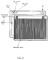
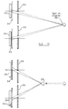
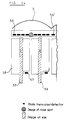
- FIG. 1 of the accompanying drawings illustrates a mechanically tracked autostereoscopic 3D display comprising a backlight 1 which illuminates a spatial light modulator (SLM) in the form of a liquid crystal device (LCD) 2.
- a movable lenticular screen 3 is disposed between the observer and the LCD 2 and comprises a plurality of cylindrically converging lenticules such as 4.
- Each lenticule 4 is optically aligned with two columns of picture elements (pixels) such as 5 and 6.
- Alternate columns of pixels display vertical strips of a respective 2D image and the lenticules 4 direct light from the backlight passing through the columns 5 and 6 into two viewing zones 7 and 8 for the left and right eyes of an observer.
- An observer tracking sensor (not shown) detects the position of the observer and the lenticular screen 3 is moved laterally with respect to the LCD 2 in response to the observer measured position so that the left and right eyes of the observer are maintained in the viewing zones 7 and 8, respectively.
- the display shown in Figure 2 of the accompanying drawings differs from that shown in Figure 1 in that the lenticular screen is replaced by a parallax barrier 3.
- the parallax barrier 3 comprises a plurality of parallel evenly spaced vertical slits such as 4 which form the viewing zones 7 and 8 in essentially the same way as the lenticules of the display shown in Figure 1.
- the parallax barrier 3 is movable laterally with respect to the LCD 2 as indicated by arrows 9 and 10 so as to track lateral movement of the observer as indicated by an arrow 11.
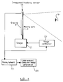
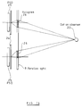
- the moving optic 3 which may be the lenticular screen or the parallax barrier shown in Figures 1 and 2, is mechanically connected to an electromechanical actuator 12, such as a voice coil stage.
- the stage 12 is controlled by a stage controller 13 in the form of a servo having positional feedback indicated at 14.
- a tracking sensor 15 measures the position of the observer 16 and supplies the measurement signals to an arrangement 17 for converting the signals from the sensor 15 into a measurement of the position of the observer 16 relative to the display.
- the measured position is then compared with a display calibration 18 so as to determine the appropriate position of the moving optic 3 relative to the LCD 2.
- the calibration comprises information stored in a look-up table determined as a result of calibrating the display.
- the required movement of the moving optic 3 is determined at 19 and supplied to the stage controller 13. The moving optic 3 is thus moved so that the observer eyes remain in the viewing zones.
- the tracking sensor 15 may comprise a video camera connected to an image processor for detecting the position of the head of the observer.
- image processor for detecting the position of the head of the observer.
- Another known type of tracking sensor uses a magnetic position detector.
- Such systems are prone to magnetic interference and require the user to wear a detector attached to the display by a cable.
- Another type of tracking sensor relies on detecting the position of the head of the observer by means of reflection of infrared by the observer or by a retro-reflective spot, for instance stuck on the forehead of the observer.
- the reflected infrared radiation is imaged by a lens on to a position sensitive detector (PSD) as shown in Figure 4 of the accompanying drawings.
- An infrared light emitting diode (LED) 20 emits infrared light which is supplied via an illumination lens 21 to illuminate a region in front of the display where an observer may be tracked.
- the infrared light reflected from the retro-reflecting dot or target 22 is collected by a collection lens 23 and is imaged through an infrared-passing filter 24 on the PSD 25.
- the PSD 25 may be of known type and supplies data indicating the position on the light-sensitive surface thereof of the "centre of gravity" of illumination "or centre of illumination”.
- an observer tracking directional display comprising an image display and a parallax optic, characterised by a first optical radiation sensor fixed with respect to one of the image display and the parallax optic, a first optical element fixed with respect to the other of the image display and the parallax optic and arranged to image optical radiation from an observer on the first sensor, and means responsive to the first sensor for controlling the supply of left eye and right eye images to the observer.
- the first sensor may be sensitive to infra-red radiation.
- the first sensor may be fixed to the image display and the first optical element may be fixed to the parallax optic.
- the first sensor may be disposed in an image plane of the image display.
- the first optical element may comprise part of the parallax optic.
- the parallax optic may comprise a plurality of parallax elements and the first sensor may comprise a plurality of sensor elements, each of which is associated with a respective one of the parallax elements.
- the controlling means may be arranged to adjust the relative lateral positions of the image display and parallax elements or the parallax of the parallax optic so as to the maintain an image of the optical radiation from the observer at a substantially constant position on the first sensor.
- the controlling means may be arranged to move the parallax optic with respect to the image display.
- the parallax optic may comprise a spatial light modulator arranged to simulate a parallax barrier having a plurality of apertures and the controlling means may be arranged to control the positions of the apertures.
- the apertures may be slits.
- the first sensor may comprise a position sensitive detector.
- the position sensitive detector may be a one or two dimensional position sensitive detector.
- the position sensitive detector may comprise an optically uncovered integrated circuit dynamic random access memory.
- the controlling means may be arranged to switch off the image display or a light source for illuminating the image display when the width of an image of the optical radiation from the observer on the first sensor exceeds a pre-determined width.
- the controlling means may be arranged to fade display of an image progressively as the width of an image of the optical radiation from the observer on the first sensor approaches a pre-determined width.
- the display may comprise: a second optical radiation sensor fixed with respect to one of the image display and parallax optic; and a second optical element fixed with respect to the other of the image display and the parallax optic and arranged to image optical radiation from the observer on the second sensor.
- the second sensor and the second optical element may be substantially identical to the first sensor and the first optical element, respectively.
- the second sensor and the second optical element may be laterally spaced from the first sensor and the first optical element, respectively.
- the controlling means may be arranged to adjust the relative lateral positions of the image display and parallax element of the parallax optic so that the position of an image of the optical radiation from the observer on the first sensor is displaced form a first pre-determined position by an amount equal and in an opposite direction to a displacement from a second pre-determined position of an image of the optical radiation from the observer on the second sensor.
- the controlling means may be arranged to adjust the relative lateral and longitudinal positions of the image display and parallax elements of the parallax optic so as to maintain images of the optical radiation from the observer at substantially constant positions on the first and second sensors.
- the display may comprise at least one optical radiation source fixed with respect to one of the image display and the parallax optic and a respective beam forming optic fixed with respect to the other of the image display and the parallax optic and arranged to form radiation from the or each source into a beam.
- the source or one of the sources may be disposed adjacent to the first sensor and the respective beam forming optic may comprise the first optical element.
- the first optical element may comprise a holographic optical element.
- the image display and the parallax optic may be arranged to form at least three viewing zones in each of at least two lobes and the controlling means may be arranged to change images in the viewing zones.
- the image display may comprise laterally substantially contiguous columns of picture elements and the first sensor may comprise a plurality of sensor elements, each of which is vertically aligned with the edge of a respective adjacent pair of columns.
- the image display may comprise a spatial light modulator.
- the spatial light modulator may comprise a liquid crystal device.
- the liquid crystal device may be an active matrix device.
- the first sensor may comprise at least one optically exposed thin film transistor in an active matrix layer of the device.
- the display may comprise an image controller responsive to the first sensor for controlling image data supplied to the image display so as to provide look-around viewing.
- an observer tracking illumination system for a directional display comprising a light source and an optical system for directing light from the light source into a plurality of viewing zones, characterised by a first optical radiation sensor fixed with respect to the light source, a first optical element fixed with respect to the optical system and arranged to image optical radiation from an observer on the first sensor, and means responsive to the first sensor for controlling at least one of the light source and the optical system for tracking the observer with the viewing zones.
- the light source may be movable with respect to the optical system.
- the light source may comprise a plurality of light source elements and the optical system may comprise a plurality of viewing zone forming elements.
- the light source may comprise an illuminator and a spatial light modulator arranged to simulate a parallax barrier having a plurality of apertures forming the light source elements and the controlling means may be arranged to control the positions of the apertures.
- the apertures may b slits.
- the spatial light modulator may be a liquid crystal device.
- the optical system may be a parallax optic, such as a lens array.
- the first optical element may comprise the optical system.
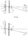
- the observer tracking autostereoscopic 3D display shown in Figure 5 is of a type similar to that shown in Figure 2 and comprises an LCD panel 2 associated with a parallax optic 3 shown in the form of a parallax barrier.
- the parallax barrier 3 has been shown displaced forwardly from the LCD panel 2 in Figure 5.
- the parallax barrier 3 is movable laterally and optionally longitudinally with respect to the panel 2.
- a PSD system of the type shown in Figure 4 is provided in the display.
- infrared light emitting diodes (LED) 20 provide a source of infrared illumination and a PSD 25 is disposed behind a filter 24 for passing infrared radiation and for attenuating or blocking other radiation.
- the PSD 25 is fixed to or integrally formed within the LCD panel 2.
- the collection lens 23 of Figure 4 is replaced by an extended slit 26 so as to provide an optical element which images infrared radiation reflected from an observer or from a reflective dot worn by the observer through the filter 24 onto the PSD 25.
- the optical element thus moves with the parallax optic 3 during observer tracking.
- the display may be operated with one or two PSD systems as described hereinafter.
- a second substantially identical system 27 is laterally spaced symmetrically from the first system.
- the display is considerably simplified with respect to the known type of observer tracking display shown in Figure 3.
- no positional feedback 14 is required.
- the measurement, comparison, and calculation functions 17, 18 and 19 are not required.
- the measurement stage 17 may be provided so as to control, for instance, a look-around computer image generation arrangement 28. In this case, observer movement is used to control the images supplied to the display 2 so as to permit 3D viewing from a different viewpoint.
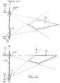
- Figure 7 Operation of the observer tracking system is illustrated in Figure 7.
- the upper part of Figure 7 illustrates the relative positions of the slit 26 which is attached to or integral with the parallax optic 3 and the PSD 25 which is fixed to the LCD panel 2. Operation is illustrated for a single PSD system disposed laterally centrally of the display.
- the observer wears a reflective dot or target 22 which improves signal-to-noise ratio.
- the target 22 and hence the observer are assumed to be located directly in front of the middle of the display.
- the region throughout which an observer may be tracked is irradiated by infrared radiation from the LEDs 20 and the target 22 reflects the infrared radiation back towards the display.
- the slit 26 acts as an optical element which causes the centre of the PSD 25 to be illuminated.
- the stage controller 13 positions the parallax optic 3 so that the slit 26 images the radiation at the centre of the PSD 25, which is embodied as a lateral one dimensional array but may be embodied in other ways.
- the slit 26 images the radiation on a part of the PSD 25 which is displaced from the centre thereof.
- the PSD 25 supplies a signal to the controller 13 indicating the amount and direction of the displacement.
- the controller 13 controls the stage 12 so as to move the parallax optic 3 and hence the slit 26 in the direction of arrow 30 until the infrared radiation reflected from the target 22 is again imaged by the slit 26 on to the centre of the PSD 25.
- the signal from the PSD 25 is used directly as a feedback signal for the stage 12 so that the signal from the PSD 25 is minimised through stage movement without any direct measurement being taken.
- the LCD 2 comprises an SLM of the type disclosed in EP 0 625 861 and having two laterally contiguous columns of pixels aligned with each slit of the parallax barrier 3.
- the centre of the PSD 25 is disposed on the vertical line between adjacent contiguous pixel columns so that, when the parallax optic 26 is positioned such that the reflected infrared radiation from the target 22 is imaged at the centre of the PSD 25, viewing zones from the adjacent contiguous columns of pixels are formed such that the left and right eyes of the observer are disposed in the left and right viewing zones, respectively.
- the target 22 is worn, for instance, on the middle of the forehead or on the bridge of the nose of the observer.
- the boundary between the two viewing zones substantially tracks the target 22 so that, within the limits of the viewing region and of the speed of observer movement, the eyes remain within the correct viewing zones at all times.
- the pixels need not be contiguous but may, for example, be of the super high aperture type as found, for example, in Sharp LQ11530.
- the only “calibration" of the display relates to the positioning of the PSD 25 and relative alignment (if necessary) of the parallax optic 3 and the optic for the PSD 25.
- the PSD 25 For the contiguous two viewing zone display as described, provided the PSD 25 is positioned such that its centre is on the vertical line which is colinear with the adjacent edges of pixels in the group of two adjacent laterally contiguous columns, no further calibration is necessary.
- a single adjustment may be provided within the controller 13 such that the parallax optic 3 is at a position relative to the LCD panel 2 where the boundary between the left and right viewing windows passes through the target 22.
- the controller 13 may thus be calibrated in a single step to stop movement of the parallax optic 3 at a position where the radiation reflected by the target 22 is imaged at a point displaced from the centre of the PSD 25.
- the pupil of an eye 31 of the observer is imaged by the parallax optic 3, which is shown as a lenticular screen, onto the image plane of the LCD 2.
- This is referred to as the eye spot 32 which, in the case of a lenticular screen or a parallax barrier, is in fact a vertical strip.
- the eye spot represents the area of the LCD 2 from which light is received by the eye 31 of the observer.
- the eye spot is analogous to the spot imaged through the slit 26 of the parallax optic 3 on the PSD 25 from the target 22, or from the head of the observer where no target is worn. Any movement of the observer results in movement of the eye spots at the plane of the LCD 2. Simultaneously, the observer spot moves by the same amount on the PSD 25.
- the behaviour of the eye spots will be substantially identical to be behaviour of the observer spot so that each may be used to obtain direct information on the other.
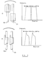
- Figure 9 illustrates the position and size of the eye spots imaged at the pixels of an LCD panel 2 together with the intensity profile.
- the upper part of Figure 9 illustrates this for an SLM of the type disclosed in EP 0 625 861 whereas the lower part of Figure 9 illustrates this for another type of conventional panel.
- Tracking of the display may be such that the eye spots do not remain at the lateral centres of adjacent pixel columns. For instance, delays in the system may result in delayed tracking of observer movement so that, until the display "locks on" to the observer again, the eye spots 32 and 33 deviate from their laterally central positions within the pixel columns.
- the upper part of Figure 9 illustrates intensity variations with lateral position of the eye spots for pixels of constant vertical aperture.
- the lower part of Figure 9 illustrates this for conventional pixel shapes of nonconstant vertical aperture.
- Such configurations would lead to intensity variations during observer tracking whereas such variations are substantially eliminated with the pixel configurations of constant vertical aperture.
- the flicker which would result from the use of conventional configurations is substantially eliminated using the configuration shown in the upper part of Figure 9.
- Figure 10 illustrates the effect of lateral tracking on display aberrations for a lenticular screen.
- the left part of Figure 10 shows equal width eye spots 32 and 33 when the observer is located on the axis of the display whereas the right part of Figure 10 illustrates the effect of large relative lateral movements.
- the eye spot 32 is of much greater width because of optical aberrations.
- the allowable viewing freedom of the display is limited by the requirement that each eye spot must remain within the pixel it is viewing, so that there is an aberrational limit on the extent of lateral observer movement as indicated at 34 and 35 in Figure 11.
- Other aberrational affects limit the longitudinal viewing range as indicated at 36 and 37. For the comfort of the observer, it is desirable not to permit viewing outside the allowed viewing range.
- the aberrations also affect the observer spot formed on the PSD 25 and this may be used to fade and/or switch off the display as the observer approaches and reaches the edges of the allowed viewing range.
- the PSD 25 supplies information about the width of the observer spot and this is compared with one or more reference values.
- the width of the observer spot is compared with a threshold value and, when this is exceeded, the backlight 1 and/or the LCD 2 are switched off.
- another comparison level is used to signal when the observer is approaching the edges of the allowed viewing range and, as the observer spot width increases above this level, the output of backlight 1 and/or the image contrast of the LCD 2 are progressively reduced.
- one of the eye spots tends to be slightly more aberrated than the other.
- optimise the system based on the position of the centre of the observer eyes. Slight performance gains may be achieved by slightly shifting the parallax optic 3 so that the more aberrated eye spot is at the centre of the associated pixels. This may be achieved by varying the optimised PSD spot position depending on its size and shape. This may be detected by recording the absolute position information of the parallax optic 3 so as to determine what the spot sizes are and positioning the parallax optic 3 with respect to the centre of gravity of the spot as measured by the PSD 25 or at the best known position for the spot.
- the use of a single PSD 25 as described hereinbefore permits only angular tracking of an observer.
- the second sensor arrangement 27 shown in Figure 5 is provided.
- the observer spots are correctly centred on both of the PSDs.
- the observer spots become displaced either side of the central position.
- the parallax optic 3 is made movable longitudinally with respect to the LCD 2.
- the lateral and longitudinal positions of the parallax optic 3 are then changed until the observer spots are centred on both of the PSDs 25.
- the observer is maintained at the window plane (lateral tracking is then performed as described hereinbefore). Both lateral and longitudinal freedom of observer movement are thereby increased.
- the parallax optic 3 cannot be moved longitudinally, movement away from the window plane has the effects shown in Figure 12 on the eye spots 32 and 33 and on the observer spots on the PSDs shown in the lower part of Figure 12.
- the eye spots 32 and 33 are laterally centred on the adjacent pixel columns.
- the observer spots move further apart whereas, as the observer moves further away from the display than the window plane, the eye spots move closer together.
- the observer spots move in a similar way as shown in the lower part of Figure 12.
- Figure 13 illustrates how the display compensates for lateral displacement of the observer from the window plane.
- the stage controller 13 receives the observer spot position information from the two PSDs 25 and moves the parallax optic 3 together with the slits 26 so that the observer spots are positioned symmetrically on the PSDs 25.
- Figure 13 illustrates that, as the target 22 approaches the display, the observer spots move outwardly from the centred position on the PSDs. Provided the displacements on the PSDs 25 remain symmetrical, the viewing zones will track the eyes of the observer within the allowed longitudinal viewing range. The longitudinal viewing range is therefore increased compared with the single PSD arrangement described hereinbefore.
- integration of the signals from the PSDs 25 can be used to assess the absolute position of the observer in order to obtain look-around data.
- "x" (lateral" and “y” (longitudinal) measurements (and “z” (height) measurements if using 2D PSDs 25) can be made by triangulation.
- the display may be faded and switched off as the observer approaches and reaches the limits. This may be detected by comparing the average deviations of the observer spots on the PSDs 25 with maximum and minimum limit values and controlling the display as described hereinbefore.
- the or each PSD 25 may be embodied in various ways.
- the PSD may comprise a linear array of detectors or an extended area silicon detector. These may be embodied as a broad area detector, a quadrant detector or a charge coupled device (CCD) array.
- a dynamic random access memory (DRAM) may be used with its cover removed and is capable of returning position information at higher resolutions than for CCD arrays but with increased noise.
- CCD array or a DRAM may permit the infrared sources 20 to be omitted and the visible image of the observer to be used by means of image processing techniques.
- image processing techniques the image of the observer is maintained centred on the two sensors by means of moving the optics systems with respect to the sensors.
- the size and shape of the observer spot may be analysed to determine the off-axis position and thus give a more accurate estimate of the observer position. This is particularly useful if the observer is not wearing a retroreflective dot so that the observer spot is extended in size compared with the interocular separation of the observer.
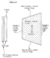
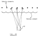
- Figure 22 illustrates another embodiment of the PSD in the form of a distributed position sensor co-operating with the parallax element 3 or an extension thereof.
- the PSD comprises a plurality of detector elements 40, for instance disposed under adjacent lenticules of a lenticular screen parallax element 3.
- Each of the detector elements 20 may be arranged simply to detect the presence or absence of radiation from the observer so that, when the observer is positioned on the axis of the display, the observer spot is on the central detector element whereas, when the observer is offset from the display axis, the observer spot falls on another of the detector elements 40.
- the resolution is given by the size of the detector element 40 covered. Imaging through side lobes of the lenticules enhances the viewing freedom of the display so that each detector element 40 can detect light in several lobes.
- the extended slits 26 of the parallax barrier shown in Figure 5 or extended lenticules of a lenticular screen may be replaced by other optical imaging elements.
- a pin hole (not shown) may be used to provide a round observer spot rather than a line or strip.
- the imaging optical elements may be part of the parallax optic 3 or may be attached to it.
- aspherical components may be used which have the same lateral imaging properties as the parallax optic 3 but which vertically collect a more defined cone of light from the general height range of observer positions so as to increase the signal-to-noise ratio.
- Figure 14 shows an arrangement in which the optical elements 26 are holograms.
- Such holographic optical elements may be particularly appropriate because the illumination wavelength may be monochromatic and the elements may be disposed on the surface of a flat substrate forming the parallax optic 3.
- Such holographic elements act in the same way as lens elements but use diffraction.
- Suitable holograms may be recorded by means of interference of two appropriately defined coherent wavefronts, for instance in materials such as dichromated gelatine or photopolymer. Further, some off-axis aberration correction may be provided.
- the element 26 may comprise lenses which may be embodied as lenticules of a lenticular screen or separate lenses which may be multiple element lenses capable of enhanced off-axis performance for maintaining a small observer spot at the PSDs 25 as the observer moves.
- Such slits, lenses and holograms may be made with the same focal length as the parallax optic 3 so that there is a direct correspondence between the movement of the parallax optic and the movement of the observer spot on the PSDs.
- Figure 16 shows an arrangement in which the focal length is made longer so that movement of the observer spot on the PSDs 25 is amplified.
- the element 26 may comprise, for example, an inverted telephoto lens or a hologram which performs this function. Such an element may be mounted in the plane of the parallax optic 3 or may be raised from the surface thereof.
- the eye spots move from position A to position B as the observer spot moves from position A to position C. Correction of the position of the parallax optic 3 brings the eye spot back to the position A but the observer spot moves to a position D which no longer corresponds to the eye spot position. Therefore, greater accuracy of observer position measurement is obtained with some demagnification of the stage movement required to maintain autostereoscopic viewing.
- the illumination sources 20 described hereinbefore are in the form of infrared LEDs which produce cones of infrared light sufficiently large to cover the whole of the observer viewing region of the display. Thus, a relatively high power device is required and light reflected other than from the observer can reduce the quality of the signal from the PSD 25.
- a scanning infrared beam may be produced by disposing the sources 20 on the LCD 2 and directing the light through optical elements such as lenses 41 disposed on the parallax optic 3.
- the resulting infrared beams as shown in Figure 17 move in conjunction with movement of the parallax optic 3 so that the illumination always points in the correct direction for the observer.
- Cylindrical lenses 41 produce a scanning light line and, by providing two such arrangements as shown, the two lines can be used to illuminate a defined region 42 in depth.
- the effects of background illumination may be substantially reduced so that only the observer is effectively illuminated. This may permit the use of the target 22 worn by the observer to be eliminated.
- the PSD 25 and the LED 20 may be integrated into a single device so as to reduce system cost. It is further possible as shown in Figure 18 to integrate the illumination and collection optics into a single hologram 26 for each combined LED/PSD.
- the hologram has two functions and thus acts as a programmed beam splitter. For light from the LED 20, a broad illumination cone is produced as indicated, for instance, at 43. Light reflected from the target 22, for instance within a beam 44, is imaged by the hologram 26 at the sensitive plane of the PSD 25.
- FIG. 19 illustrates a lateral tracking display of the type disclosed in EP 0 726 482.
- the display forms three viewing zones or windows W1, W2 and W3 which are repeated in three lobes.
- views V1 to V9 are supplied to the windows as indicated in Figure 19.
- the tracking system is required to determine when the observer eyes are located centrally within two viewing zones so that the image displayed in the window of the viewing zone to which the observer is moving can be changed without the observer being aware of this.
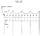
- Figure 20 illustrates a tracking arrangement for controlling view switching in displays of this type.
- Detector elements 40 are disposed so as to be aligned vertically with the adjacent edges of laterally contiguous pixels or pixel columns.
- the elements 40 thus receive light reflected from the observer through the parallax optic 3.
- the observer spot passes over a respective one of the detector elements 40 whose output triggers switching of the image data supplied in the other unobserved column of pixels aligned with the associated parallax element of the parallax optic 3.
- two sensors are disposed at a quarter of the pixel width in from each side of the pixel to achieve appropriate switching positions.
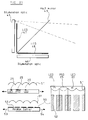
- Figure 21 shows an example of another class of autostereoscopic 3D displays in which a steerable light source is used in association with SLMs to form the viewing zones.
- the display shown in Figure 21 comprises a pair of illumination optics 45 and 46 associated with LCDs 47 and 48 for displaying the 2D images of a stereoscopic pair.
- a beam combiner in the form of a half mirror 49 combines the images so that the observer sees the image displayed by the LCD 47 with one eye and the image displayed by the LCD 48 with the other eye.
- Each of the illumination optics 45 and 46 is associated with a respective backlight (not shown) and comprises a parallax barrier 50 and a lenticular screen 51.
- the slits 52 of the parallax barrier 50 act as vertical parallel evenly spaced light sources and the light from the slits is directed by the lenticules of the lenticular screen 51 into viewing zones through the respective image LCD.
- the parallax barrier 50 is moved laterally with respect to the lenticular screen 51 in directions indicated by the arrows 53 and 54.
- the barrier may comprise a spatial light modulator simulating a parallax barrier to permit movement of the slits electronically, for instance as disclosed in British Patent Application No: 9620210.6.
- the observer position information to permit observer tracking is provided by a PSD 25 and infrared LEDs 20 which are mounted or formed on the surface of the parallax barrier 50.
- the PSD 25 and the LEDs 20 are covered by the lenticular screen 51 which extends above the slits 52 of the parallax barrier 50.
- the observer position measuring arrangement thus functions as described hereinbefore and forms a scanning illumination beam in the same way as the arrangement disclosed in Figure 17.
- the viewing zones thus track the observer.
- the observer position measuring arrangement is provided on the illumination optic 45. Because the LCD 47 would attenuate light from the LEDs 20 and light returning to the PSD 25, the part of the illumination optic 45 where this arrangement is provided is not covered by the LCD 47.
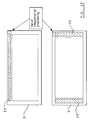
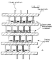
- FIG 23 illustrates how room may be found on the LCD 2 for PSDs 25 and for processing electronics which may be formed integrally as part of the LCD, for example with polysilicon transistors. Two layouts are shown for providing the PSDs 25 and optional processing electronics 55.
- the PSD 25 By incorporating the PSD 25 in the LCD panel 3, a cost advantage may be obtained by using the same deposition process as used for the LCD electronics.
- the same or similar transistors as used in the display area of the panel may be used as photo-sensitive devices by, for instance, removing parts of the black mask which usually covers the active transistor elements.
- the tracking system may be provided at little or no additional cost. Further, such an arrangement is more rugged and does not require a subsequent registration phase because registration is provided by the lithography which accurately defines the positions of the PSDs and the LCD pixels during fabrication.
- Figure 24 illustrates a possible layout in which the PSD is provided by a linear array of nine phototransistors 56.
- the transistors may be of the same type as thin film transistors such as 57 used to address pixels such as 58 of the LCD 2. More preferably, the transistors are of amorphous silicon optimised for photosensitivity.
- further transistors such as 56' in equivalent positions under adjacent lenticules may be used to improve the signal-to-noise ratio.
- Figure 25 illustrates another arrangement of SLM of the type disclosed in EP 0 625 861 for providing two viewing windows in a mechanically tracked system.
- the correct viewing position is indicated with the eye spots 32 and 33 as shown.
- the light reflected from the nose spot 60 is indicated by the circle.
- This best position is defined by equal amounts of light from the nose spot impinging on the transistors 57 under the respective eye spots 32 and 33. This condition can be detected by processing the difference in signal from these transistors and selecting the minimum. Deviations from this position will result in an increase in signal from one transistor and a decrease in the signal from the other.
- Figure 25 shows just one nose spot, but clearly the same condition is repeated along the panel and the output from multiple equivalent transistors can be used to improve signal-to-noise ratio as required.
- the pseudoscopic zone position can be discriminated against by, for example, not using the signal from every "3rd pixel" as shown.
- the signal from the transistors is used to control the mechanical position of the associated parallax generating element so as to maintain the observer position in the correct orthoscopic 3D zone.
- the panel signals can be further processed to provide an absolute observer position signaL so as to enable the provision of a look-around capability.
- a datum switch may be required to establish a starting position for the parallax optic.
- Figure 26 illustrates a possible layout using a standard high aperture panel to provide a two window mechanically tracked arrangement.
- the transistors 59 which would normally be used to address pixels 58 are instead uncovered and used as detectors for detecting the observer spot 60. In this case, the correct viewing condition is detected by maximising the positive difference between the outputs of the transistor under the spot 60 and the transistor 59.
- Figure 27 shows an arrangement in which the sensor transistors are addressed in the same way as the display transistors by a matrix arrangement comprising row electrodes such as 61 and column electrodes such as 62.
- a matrix arrangement comprising row electrodes such as 61 and column electrodes such as 62.
- Such an addressing arrangement is of the well-known active matrix type.
- the sensor pixels 63 are initially charged via the transistors so that light from the nose spot impinging on the uncovered transistors increases their leakage current, thus discharging the associated pixel. Depending on light intensity and exposure time, the sensor pixel capacitance is progressively discharged. This period of exposure time can be used to increase the sensitivity of the detector but cannot be made too long if observer position lag is important. Such times are preferably below 100 milliseconds and more preferably below 20 milliseconds.
- each row of sensor transistors is again addressed for a read operation.
- the transistors of the selected row are turned on and the residual charge is read out of the sensor pixels of the row by the column electrodes.
- Suitable times for readout include the vertical retrace time, in which the LCD panel 2 is electrically quiet, and the horizontal blanking time. Readout during a period in which the panel is electrically quiet can improve signal detection conditions.
- Figure 28 shows an SLM of the same type as shown in Figure 25 but operated in a three window mode suitable for electronic steering with no moving parts.
- the left and right image channels need to be routed to different pixels sets as the observer moves.
- P1, P2 and P3 illustrate the image at the panel plane of the observer eyes and nose as he moves laterally over a small region.
- the switching point and conditions at each point at which the image channels are routed to different sets of pixels are indicated.
- This device has the ability to perform the required switching functions totally internally without the need for an external multiplexer to switch the left and right images as the observer moves.
- the photodetector properties of the transistors may be improved by changing the geometry and/or deposition conditions of the transistors.
- the display backlight when present may be used.
- an infrared phosphor could be added to florescent tubes within the backlight.
- separate infrared emitters may be provided within the backlight.
- the infrared wavelength may be chosen to avoid absorption by polarisers within the LCD 2.
- the polarisers may be removed or omitted from the sensor area.
- Phase or synchronous detection techniques may be used to improve the signal-to-noise ratio.
Abstract
Description
Claims (41)
- An observer tracking directional display comprising an image display (2) and a parallax optic (3), characterised by a first optical radiation sensor (25) fixed with respect to one of the image display (2) and the parallax optic (3), a first optical element (26) fixed with respect to the other of the image display (2) and the parallax optic (3) and arranged to image optical radiation from an observer on the first sensor (25), and means (12, 13, 17, 28) responsive to the first sensor for controlling the supply of left eye and right eye images to the observer.
- A display as claimed in Claim 1 characterised in that the first sensor (25) is sensitive to infrared radiation.
- A display as claimed in Claim 1 or 2 characterised in that the first sensor (25) is fixed to the image display (2) and the first optical element (26) is fixed to the parallax optic (3).
- A display as claimed in Claim 3, characterised in that the first sensor (25) is disposed in an image plane of the image display (2).
- A display as claimed in Claim 3 or 4, in which the first optical element (26) comprises part of the parallax optic (3).
- A display as claimed in Claim 5, characterised in that the parallax optic (3) comprises a plurality of parallax elements and the first sensor (3) comprises a plurality of sensor elements (4), each of which is associated with a respective one of the parallax elements.
- A display as claimed in any one of the preceding claims, characterised in that the controlling means (12, 13) is arranged to adjust the relative lateral positions of the image display (2) and parallax elements or the parallax elements of the parallax optic (3) so as to maintain an image of the optical radiation from the observer at a substantially constant position on the first sensor (25).
- A display as claimed in any one of the preceding claims, characterised in that the controlling means (12, 13) is arranged to move the parallax optic (3) with respect to the image display (2).
- A display as claimed in any one of Claims 1 to 7, characterised in that the parallax optic (3) comprises a spatial light modulator arranged to simulate a parallax barrier having a plurality of apertures and the controlling means (12, 13) is arranged to control the positions of the apertures.
- A display as claimed in Claim 9, characterised in that the apertures are slits.
- A display as claimed in any one of Claims 1 to 5 or in any one of Claims 7 to 10 when not dependent on Claim 6, characterised in that the first sensor (25) comprises a position sensitive detector.
- A display as claimed in Claim 11, characterised in that the position sensitive detector (25) is a one dimensional position sensitive detector.
- A display as claimed in Claim 11, characterised in that the position sensitive detector (25) is a two dimensional position sensitive detector.
- A display as claimed in Claim 13, characterised in that the position sensitive detector (25) comprises an optically uncovered integrated circuit dynamic random access memory.
- A display as claimed in any one of the preceding claims, characterised in that the controlling means (12, 13, 17, 28) is arranged to switch off the image display (2) or a light source (1) for illuminating the image display (2) when the width of an image (32, 33) of the optical radiation from the observer on the first sensor (25) exceeds a predetermined width.
- A display as claimed in any one of Claims 1 to 14, characterised in that the controlling means (12, 13, 17, 28) is arranged to fade display of an image progressively as the width of an image (32, 33) of the optical radiation from the observer on the first sensor (20) approaches a predetermined width.
- A display as claimed in any one of the preceding claims, characterised in that a second optical radiation sensor (25) fixed with respect to the one of the image display (2) and the parallax optic (3); and a second optical element (26) fixed with respect to the other of the image display (2) and the parallax optic (3) and arranged to image optical radiation from the observer on the second sensor (25).
- A display as claimed in Claim 17, characterised in that the second sensor (25) and the second optical element (26) are substantially identical to the first sensor (25) and the first optical element (26), respectively.
- A display as claimed in Claim 17 or 18, characterised in that the second sensor and the second optical element (26) are laterally spaced from the first sensor (25) and the first optical element (26), respectively.
- A display as claimed in any one of Claims 17 to 19, characterised in that the controlling means (12, 13, 17, 28) is arranged to adjust the relative lateral positions of the image display (2) and parallax elements of the parallax optic (3) so that the position of an image of the optical radiation from the observer on the first sensor (25) is displaced from a first predetermined position by an amount equal and in an opposite direction to a displacement from a second predetermined position of an image of the optical radiation from the observer on the second sensor (25).
- A display as claimed in any one of Claims 17 to 19, characterised in that the controlling means (12, 13, 17, 28) is arranged to adjust the relative lateral and longitudinal positions of the image display (2) and parallax elements of the parallax optic (3) so as to maintain images of the optical radiation from the observer at substantially constant positions on the first and second sensors (25).
- A display as claimed in any one of the preceding claims, characterised in that at least one optical radiation (20) source fixed with respect to the one of the image display (2) and the parallax optic (3) and a respective beam forming optic (41) fixed with respect to the other of the image display (2) and the parallax optic (3) and arranged to form radiation from the or each source into a beam.
- A display as claimed in Claim 22, characterised in that the source (20) or one of the sources (20) is disposed adjacent the first sensor (25)and the respective beam forming optic comprises the first optical element (26).
- A display as claimed in Claim 23, characterised in that the first optical element (26) comprises a holographic optical element.
- A display as claimed in Claim 1, characterised in that the image display (2) and the parallax optic (3) are arranged to form at least three viewing zones in each of at least two lobes and the controlling means (12, 13, 17, 28) is arranged to change images in the viewing zones.
- A display as claimed in Claim 25, characterised in that the image display (2) comprises laterally substantially contiguous columns of picture elements and the first sensor comprises a plurality of sensor elements (40), each of which is vertically aligned with the edges of a respective adjacent pair of columns.
- A display as claimed in any one of the preceding claims, characterised in that the image display (2) comprises a spatial light modulator.
- A display as claimed in Claim 27, characterised in that the spatial light modulator (2) comprises a liquid crystal device.
- A display as claimed in Claim 28, characterised in that the liquid crystal device (2) is an active matrix device.
- A display as claimed in Claim 29, characterised in that the first sensor comprises at least one optically exposed thin film transistor (57) in an active matrix layer of the device.
- A display as claimed in any one of the preceding claims, characterised by an image controller (28) responsive to the first sensor (25) for controlling image data supplied to the image display (2) so as to provide look-around viewing.
- An observer tracking illumination system for a directional display, comprising a light source (1, 50) and an optical system (51) for directing light from the light source (1, 50) into a plurality of viewing zones, characterised by a first optical radiation sensor (25) fixed with respect to the light source (1, 50), a first optical element fixed with respect to the optical system (51) and arranged to image optical radiation from an observer on the first sensor (25), and means (12, 13, 17, 28) responsive to the first sensor (25) for controlling at least one of the light sources (1, 51) and the optical system (51) for tracking the observer with the viewing zones.
- A system as claimed in Claim 32, characterised in that the light source (1, 50) is movable with respect to the optical system (51).
- A system as claimed in Claim 32 or 33, characterised in that the light source (1, 50) comprises a plurality of light source elements (52) and the optical system comprises a plurality of viewing zone forming elements.
- A system as claimed in Claim 34, characterised in that the light source elements (52) are movable with respect to the viewing zone forming elements.
- A system as claimed in Claim 35, characterised in that the light source comprises an illuminator (1) and a spatial light modulator (50) arranged to simulate a parallax barrier having a plurality of apertures (52) forming the light source elements and the controlling means (12, 13, 17, 28) is arranged to control the positions of the apertures (52).
- A system as claimed in Claim 36, characterised in that the apertures (52) are slits.
- A system as claimed in Claim 36 or 37, characterised in that the spatial light modulator (50) is a liquid crystal device.
- A system as claimed in any one of Claims 32 to 38, characterised in that the optical system is a parallax optic (51).
- A system as claimed in Claim 39, characterised in that the parallax optic is a lens array (51).
- A systems as claimed in any one of Claims 32 to 40, characterised in that the first optical element comprises the optical system (51).
Applications Claiming Priority (2)
| Application Number | Priority Date | Filing Date | Title |
|---|---|---|---|
| GB9620261 | 1996-09-27 | ||
| GB9620261A GB2317771A (en) | 1996-09-27 | 1996-09-27 | Observer tracking directional display |
Publications (3)
| Publication Number | Publication Date |
|---|---|
| EP0833182A2 true EP0833182A2 (en) | 1998-04-01 |
| EP0833182A3 EP0833182A3 (en) | 1998-04-08 |
| EP0833182B1 EP0833182B1 (en) | 2004-06-23 |
Family
ID=10800644
Family Applications (1)
| Application Number | Title | Priority Date | Filing Date |
|---|---|---|---|
| EP97307570A Expired - Lifetime EP0833182B1 (en) | 1996-09-27 | 1997-09-26 | Observer tracking autostereoscopic display |
Country Status (5)
| Country | Link |
|---|---|
| US (1) | US6008484A (en) |
| EP (1) | EP0833182B1 (en) |
| JP (1) | JP3401169B2 (en) |
| DE (1) | DE69729616T2 (en) |
| GB (1) | GB2317771A (en) |
Cited By (11)
| Publication number | Priority date | Publication date | Assignee | Title |
|---|---|---|---|---|
| WO2003049072A1 (en) * | 2001-12-04 | 2003-06-12 | Koninklijke Philips Electronics N.V. | Directional image display |
| EP1396749A1 (en) * | 2001-06-01 | 2004-03-10 | Sony Corporation | 3-d image display unit, display unit, or split wavelength plate filter mounted on these dsplay units, platy filter, and filter position adjusting mechanism, positioning device, and filter position adjusting method, positioning method |
| WO2005053319A1 (en) * | 2003-11-25 | 2005-06-09 | Siemens Aktiengesellschaft | Covering element, especially for an optical module, and method for producing the same |
| WO2008003373A1 (en) * | 2006-07-06 | 2008-01-10 | Fraunhofer-Gesellschaft zur Förderung der angewandten Forschung e.V. | Method for the autostereoscopic presentation of image information with adaptation to suit changes in the head position of the observer |
| EP2689284A2 (en) * | 2011-03-22 | 2014-01-29 | Bayer Intellectual Property GmbH | Electroactive polymer actuator lenticular system |
| US9231186B2 (en) | 2009-04-11 | 2016-01-05 | Parker-Hannifin Corporation | Electro-switchable polymer film assembly and use thereof |
| US9425383B2 (en) | 2007-06-29 | 2016-08-23 | Parker-Hannifin Corporation | Method of manufacturing electroactive polymer transducers for sensory feedback applications |
| US9553254B2 (en) | 2011-03-01 | 2017-01-24 | Parker-Hannifin Corporation | Automated manufacturing processes for producing deformable polymer devices and films |
| US9590193B2 (en) | 2012-10-24 | 2017-03-07 | Parker-Hannifin Corporation | Polymer diode |
| US9761790B2 (en) | 2012-06-18 | 2017-09-12 | Parker-Hannifin Corporation | Stretch frame for stretching process |
| US9876160B2 (en) | 2012-03-21 | 2018-01-23 | Parker-Hannifin Corporation | Roll-to-roll manufacturing processes for producing self-healing electroactive polymer devices |
Families Citing this family (76)
| Publication number | Priority date | Publication date | Assignee | Title |
|---|---|---|---|---|
| US6556236B1 (en) * | 1992-11-16 | 2003-04-29 | Reveo, Inc. | Intelligent method and system for producing and displaying stereoscopically-multiplexed images of three-dimensional objects for use in realistic stereoscopic viewing thereof in interactive virtual reality display environments |
| JPH10232626A (en) * | 1997-02-20 | 1998-09-02 | Canon Inc | Stereoscopic image display device |
| JPH1138360A (en) * | 1997-07-22 | 1999-02-12 | Hitachi Ltd | Method and device for reproducing stereoscopic image, and directional reflection screen |
| AUPP048097A0 (en) * | 1997-11-21 | 1997-12-18 | Xenotech Research Pty Ltd | Eye tracking apparatus |
| GB2337388A (en) * | 1998-05-12 | 1999-11-17 | Sharp Kk | Directional autereoscopic 3D display having directional illumination system |
| US6795241B1 (en) * | 1998-12-10 | 2004-09-21 | Zebra Imaging, Inc. | Dynamic scalable full-parallax three-dimensional electronic display |
| GB9900231D0 (en) * | 1999-01-07 | 1999-02-24 | Street Graham S B | Method and apparatus for control of viewing zones |
| TW536646B (en) * | 1999-12-24 | 2003-06-11 | Ind Tech Res Inst | Back-lighted auto-stereoscopic display |
| JP2001356298A (en) * | 2000-06-12 | 2001-12-26 | Denso Corp | Stereoscopic video display device |
| EP1245990A1 (en) * | 2001-03-28 | 2002-10-02 | Dimensional Developments ApS | Self alignment 3-D display |
| WO2002080579A2 (en) * | 2001-03-28 | 2002-10-10 | Dimensional Developments Aps | Self-aligning autostereoscopic 3d display |
| DE10242262A1 (en) * | 2002-09-12 | 2004-03-25 | Daimlerchrysler Ag | Stereo vision system for assisting night vision in vehicles has arrangement for generating stereoscopic reproduction of image signals acquired by at least two night vision-compatible cameras |
| EP1709622A1 (en) * | 2004-01-20 | 2006-10-11 | Koninklijke Philips Electronics N.V. | Message board with dynamic message relocation |
| TW200604712A (en) * | 2004-06-08 | 2006-02-01 | Actuality Systems Inc | Optical scanning assembly |
| WO2006100856A1 (en) * | 2005-03-24 | 2006-09-28 | Sharp Kabushiki Kaisha | Display unit |
| US8675125B2 (en) | 2005-04-27 | 2014-03-18 | Parellel Consulting Limited Liability Company | Minimized-thickness angular scanner of electromagnetic radiation |
| JP5465430B2 (en) * | 2005-06-07 | 2014-04-09 | リアルディー インコーポレイテッド | Control of angle range of autostereoscopic viewing zone |
| JP4579295B2 (en) * | 2005-07-25 | 2010-11-10 | パイオニア株式会社 | Image display device |
| WO2007065244A1 (en) * | 2005-12-06 | 2007-06-14 | Dolby Laboratories Licensing Corporation | Modular electronic displays |
| US9104270B2 (en) | 2006-05-22 | 2015-08-11 | Thomson Licensing | Video system having a touch screen |
| JP5006587B2 (en) | 2006-07-05 | 2012-08-22 | 株式会社エヌ・ティ・ティ・ドコモ | Image presenting apparatus and image presenting method |
| US8491121B2 (en) | 2007-10-09 | 2013-07-23 | Elbit Systems Of America, Llc | Pupil scan apparatus |
| US20090159799A1 (en) * | 2007-12-19 | 2009-06-25 | Spectral Instruments, Inc. | Color infrared light sensor, camera, and method for capturing images |
| WO2010019923A1 (en) * | 2008-08-14 | 2010-02-18 | Real D | Autostereoscopic display system with efficient pixel layout |
| WO2010045364A1 (en) * | 2008-10-14 | 2010-04-22 | Real D | Lenticular display systems with offset color filter array |
| TWI395977B (en) * | 2008-12-26 | 2013-05-11 | Ind Tech Res Inst | Stereoscopic disply apparatus and display method |
| US8284234B2 (en) | 2009-03-20 | 2012-10-09 | Absolute Imaging LLC | Endoscopic imaging using reflection holographic optical element for autostereoscopic 3-D viewing |
| WO2010119592A1 (en) * | 2009-04-15 | 2010-10-21 | シャープ株式会社 | Liquid crystal display apparatus |
| GB0909126D0 (en) * | 2009-05-27 | 2009-07-01 | Qinetiq Ltd | Eye tracking apparatus |
| KR101627214B1 (en) * | 2009-11-12 | 2016-06-03 | 엘지전자 주식회사 | Image Display Device and Operating Method for the Same |
| US9106925B2 (en) * | 2010-01-11 | 2015-08-11 | Ubiquity Holdings, Inc. | WEAV video compression system |
| JP5552354B2 (en) * | 2010-04-09 | 2014-07-16 | 株式会社三共 | Game machine |
| TWI429947B (en) * | 2010-08-03 | 2014-03-11 | Chunghwa Picture Tubes Ltd | Stereoscopic image displaying method and stereoscopic display device |
| KR101670927B1 (en) * | 2010-11-05 | 2016-11-01 | 삼성전자주식회사 | Display apparatus and method |
| CN101984670B (en) * | 2010-11-16 | 2013-01-23 | 深圳超多维光电子有限公司 | Stereoscopic displaying method, tracking stereoscopic display and image processing device |
| KR20120075174A (en) * | 2010-12-28 | 2012-07-06 | 삼성모바일디스플레이주식회사 | Stereoscopic display apparatus |
| KR101085586B1 (en) | 2011-01-28 | 2011-11-25 | 한동희 | 3d display apparatus having variable barrier panel |
| KR20120091585A (en) * | 2011-02-09 | 2012-08-20 | 삼성전기주식회사 | Display device and method for providing 3d image of the display device |
| US9426453B2 (en) * | 2011-03-04 | 2016-08-23 | Dolby Laboratories Licensing Corporation | Methods and apparatus for 3D shutter glasses synchronization |
| US20130093752A1 (en) * | 2011-10-13 | 2013-04-18 | Sharp Laboratories Of America, Inc. | Viewer reactive auto stereoscopic display |
| JP5762998B2 (en) * | 2012-03-07 | 2015-08-12 | 株式会社ジャパンディスプレイ | Display device and electronic device |
| US9678267B2 (en) | 2012-05-18 | 2017-06-13 | Reald Spark, Llc | Wide angle imaging directional backlights |
| US9709723B2 (en) | 2012-05-18 | 2017-07-18 | Reald Spark, Llc | Directional backlight |
| US9235057B2 (en) | 2012-05-18 | 2016-01-12 | Reald Inc. | Polarization recovery in a directional display device |
| JP6508832B2 (en) | 2012-05-18 | 2019-05-08 | リアルディー スパーク エルエルシー | Control of multiple light sources in directional backlights |
| US9188731B2 (en) | 2012-05-18 | 2015-11-17 | Reald Inc. | Directional backlight |
| US9584797B2 (en) | 2012-10-31 | 2017-02-28 | Elwha Llc | Systems and methods to confirm that an autostereoscopic display is accurately aimed |
| KR20140063272A (en) * | 2012-11-16 | 2014-05-27 | 엘지전자 주식회사 | Image display apparatus and method for operating the same |
| EP2959213A4 (en) | 2013-02-22 | 2016-11-16 | Reald Inc | Directional backlight |
| CN110234000B (en) | 2013-06-17 | 2021-07-13 | 瑞尔D斯帕克有限责任公司 | Teleconferencing method and telecommunication system |
| CN106068533B (en) | 2013-10-14 | 2019-01-11 | 瑞尔D斯帕克有限责任公司 | The control of directional display |
| WO2015057588A1 (en) | 2013-10-14 | 2015-04-23 | Reald Inc. | Light input for directional backlight |
| JP6962521B2 (en) | 2014-06-26 | 2021-11-05 | リアルディー スパーク エルエルシー | Directional privacy display |
| EP3204686B1 (en) | 2014-10-08 | 2019-07-17 | RealD Spark, LLC | Connection unit for a directional backlight |
| WO2016105541A1 (en) | 2014-12-24 | 2016-06-30 | Reald Inc. | Adjustment of perceived roundness in stereoscopic image of a head |
| US20160255323A1 (en) | 2015-02-26 | 2016-09-01 | Dual Aperture International Co. Ltd. | Multi-Aperture Depth Map Using Blur Kernels and Down-Sampling |
| RU2596062C1 (en) | 2015-03-20 | 2016-08-27 | Автономная Некоммерческая Образовательная Организация Высшего Профессионального Образования "Сколковский Институт Науки И Технологий" | Method for correction of eye image using machine learning and method of machine learning |
| EP3283911B1 (en) | 2015-04-13 | 2021-12-08 | RealD Spark, LLC | Wide angle imaging directional backlights |
| US10228505B2 (en) | 2015-05-27 | 2019-03-12 | Reald Spark, Llc | Wide angle imaging directional backlights |
| EP3369034B1 (en) | 2015-10-26 | 2023-07-05 | RealD Spark, LLC | Intelligent privacy system, apparatus, and method thereof |
| WO2017083526A1 (en) | 2015-11-10 | 2017-05-18 | Reald Inc. | Distortion matching polarization conversion systems and methods thereof |
| EP3374822B1 (en) | 2015-11-13 | 2023-12-27 | RealD Spark, LLC | Surface features for imaging directional backlights |
| US10330843B2 (en) | 2015-11-13 | 2019-06-25 | Reald Spark, Llc | Wide angle imaging directional backlights |
| CN108463787B (en) | 2016-01-05 | 2021-11-30 | 瑞尔D斯帕克有限责任公司 | Gaze correction of multi-perspective images |
| US10609365B2 (en) * | 2016-04-05 | 2020-03-31 | Disney Enterprises, Inc. | Light ray based calibration system and method |
| CN109416431B (en) | 2016-05-19 | 2022-02-08 | 瑞尔D斯帕克有限责任公司 | Wide-angle imaging directional backlight |
| WO2017205183A1 (en) | 2016-05-23 | 2017-11-30 | Reald Spark, Llc | Wide angle imaging directional backlights |
| WO2018129059A1 (en) | 2017-01-04 | 2018-07-12 | Reald Spark, Llc | Optical stack for imaging directional backlights |
| US10408992B2 (en) | 2017-04-03 | 2019-09-10 | Reald Spark, Llc | Segmented imaging directional backlights |
| CN107396087B (en) * | 2017-07-31 | 2019-03-12 | 京东方科技集团股份有限公司 | Naked eye three-dimensional display device and its control method |
| EP4293574A3 (en) | 2017-08-08 | 2024-04-03 | RealD Spark, LLC | Adjusting a digital representation of a head region |
| KR102401168B1 (en) * | 2017-10-27 | 2022-05-24 | 삼성전자주식회사 | Method and apparatus for calibrating parameter of 3d display apparatus |
| EP3707554B1 (en) | 2017-11-06 | 2023-09-13 | RealD Spark, LLC | Privacy display apparatus |
| CA3089477A1 (en) | 2018-01-25 | 2019-08-01 | Reald Spark, Llc | Touch screen for privacy display |
| DE102018118931A1 (en) * | 2018-08-03 | 2020-02-06 | Osram Opto Semiconductors Gmbh | Display device and operating method |
| US11821602B2 (en) | 2020-09-16 | 2023-11-21 | Reald Spark, Llc | Vehicle external illumination device |
Citations (2)
| Publication number | Priority date | Publication date | Assignee | Title |
|---|---|---|---|---|
| WO1993018428A2 (en) * | 1992-03-13 | 1993-09-16 | Kopin Corporation | Head-mounted display system |
| WO1994020875A2 (en) * | 1993-03-03 | 1994-09-15 | Street Graham S B | Method and apparatus for image alignment |
Family Cites Families (6)
| Publication number | Priority date | Publication date | Assignee | Title |
|---|---|---|---|---|
| FR2549972B1 (en) * | 1983-07-25 | 1990-01-26 | Pund Marvin | STEREOSCOPIC VISUALIZATION APPARATUS AND METHOD |
| DE3921061A1 (en) * | 1989-06-23 | 1991-01-03 | Hertz Inst Heinrich | DISPLAY DEVICE FOR THREE-DIMENSIONAL PERCEPTION OF IMAGES |
| GB2278223A (en) * | 1993-05-21 | 1994-11-23 | Sharp Kk | Spatial light modulator and directional display |
| DE69432283T2 (en) * | 1993-12-01 | 2004-01-22 | Sharp K.K. | Display for three-dimensional images |
| GB2296617A (en) * | 1994-12-29 | 1996-07-03 | Sharp Kk | Observer tracking autosteroscopic display |
| GB2297876A (en) * | 1995-02-09 | 1996-08-14 | Sharp Kk | Observer tracking autostereoscopic display |
-
1996
- 1996-09-27 GB GB9620261A patent/GB2317771A/en not_active Withdrawn
-
1997
- 1997-09-25 US US08/937,858 patent/US6008484A/en not_active Expired - Fee Related
- 1997-09-26 DE DE69729616T patent/DE69729616T2/en not_active Expired - Lifetime
- 1997-09-26 EP EP97307570A patent/EP0833182B1/en not_active Expired - Lifetime
- 1997-09-29 JP JP26469097A patent/JP3401169B2/en not_active Expired - Fee Related
Patent Citations (2)
| Publication number | Priority date | Publication date | Assignee | Title |
|---|---|---|---|---|
| WO1993018428A2 (en) * | 1992-03-13 | 1993-09-16 | Kopin Corporation | Head-mounted display system |
| WO1994020875A2 (en) * | 1993-03-03 | 1994-09-15 | Street Graham S B | Method and apparatus for image alignment |
Cited By (17)
| Publication number | Priority date | Publication date | Assignee | Title |
|---|---|---|---|---|
| EP1396749A1 (en) * | 2001-06-01 | 2004-03-10 | Sony Corporation | 3-d image display unit, display unit, or split wavelength plate filter mounted on these dsplay units, platy filter, and filter position adjusting mechanism, positioning device, and filter position adjusting method, positioning method |
| EP1396749A4 (en) * | 2001-06-01 | 2007-05-30 | Sony Corp | 3-d image display unit, display unit, or split wavelength plate filter mounted on these dsplay units, platy filter, and filter position adjusting mechanism, positioning device, and filter position adjusting method, positioning method |
| WO2003049072A1 (en) * | 2001-12-04 | 2003-06-12 | Koninklijke Philips Electronics N.V. | Directional image display |
| WO2005053319A1 (en) * | 2003-11-25 | 2005-06-09 | Siemens Aktiengesellschaft | Covering element, especially for an optical module, and method for producing the same |
| WO2008003373A1 (en) * | 2006-07-06 | 2008-01-10 | Fraunhofer-Gesellschaft zur Förderung der angewandten Forschung e.V. | Method for the autostereoscopic presentation of image information with adaptation to suit changes in the head position of the observer |
| EP2472889A1 (en) * | 2006-07-06 | 2012-07-04 | Fraunhofer-Gesellschaft zur Förderung der angewandten Forschung e.V. | Method for the autostereoscopic presentation of image information with adaptation to suit changes in the head position of the observer |
| US8319824B2 (en) | 2006-07-06 | 2012-11-27 | Fraunhofer-Gesellschaft Zur Forderung Der Angewandten Forschung E.V. | Method for the autostereoscopic presentation of image information with adaptation to suit changes in the head position of the observer |
| US9425383B2 (en) | 2007-06-29 | 2016-08-23 | Parker-Hannifin Corporation | Method of manufacturing electroactive polymer transducers for sensory feedback applications |
| US9231186B2 (en) | 2009-04-11 | 2016-01-05 | Parker-Hannifin Corporation | Electro-switchable polymer film assembly and use thereof |
| US9553254B2 (en) | 2011-03-01 | 2017-01-24 | Parker-Hannifin Corporation | Automated manufacturing processes for producing deformable polymer devices and films |
| CN103703404A (en) * | 2011-03-22 | 2014-04-02 | 拜耳知识产权有限责任公司 | Electroactive polymer actuator lenticular system |
| EP2689284A4 (en) * | 2011-03-22 | 2014-08-20 | Bayer Ip Gmbh | Electroactive polymer actuator lenticular system |
| US9195058B2 (en) | 2011-03-22 | 2015-11-24 | Parker-Hannifin Corporation | Electroactive polymer actuator lenticular system |
| EP2689284A2 (en) * | 2011-03-22 | 2014-01-29 | Bayer Intellectual Property GmbH | Electroactive polymer actuator lenticular system |
| US9876160B2 (en) | 2012-03-21 | 2018-01-23 | Parker-Hannifin Corporation | Roll-to-roll manufacturing processes for producing self-healing electroactive polymer devices |
| US9761790B2 (en) | 2012-06-18 | 2017-09-12 | Parker-Hannifin Corporation | Stretch frame for stretching process |
| US9590193B2 (en) | 2012-10-24 | 2017-03-07 | Parker-Hannifin Corporation | Polymer diode |
Also Published As
| Publication number | Publication date |
|---|---|
| JPH10115801A (en) | 1998-05-06 |
| DE69729616T2 (en) | 2005-06-30 |
| JP3401169B2 (en) | 2003-04-28 |
| DE69729616D1 (en) | 2004-07-29 |
| GB2317771A (en) | 1998-04-01 |
| US6008484A (en) | 1999-12-28 |
| EP0833182B1 (en) | 2004-06-23 |
| EP0833182A3 (en) | 1998-04-08 |
| GB9620261D0 (en) | 1996-11-13 |
Similar Documents
| Publication | Publication Date | Title |
|---|---|---|
| EP0833182B1 (en) | Observer tracking autostereoscopic display | |
| EP0829743B1 (en) | Observer tracking directional display | |
| EP0769881B1 (en) | Method of calibrating a display which tracks an observer | |
| US7414712B2 (en) | Large dynamic range Shack-Hartmann wavefront sensor | |
| US5825456A (en) | Stereoscopic video display apparatus | |
| KR100600459B1 (en) | Three-dimensional display method and device therefor | |
| CN103168272A (en) | Depth estimate image capture device and image capture element | |
| US20200075652A1 (en) | Pixel cell with multiple photodiodes | |
| CA2297611A1 (en) | Virtual multiple aperture 3-d range sensor | |
| GB2388896A (en) | An apparatus for and method of aligning a structure | |
| JPH07322301A (en) | Three-dimensional display device and screen control method therefor | |
| CN102685406A (en) | Image pickup apparatus, focus detection method and image generation method | |
| WO2010123854A1 (en) | Endoscopic imaging using reflection holographic optical element for autostereoscopic 3-d viewing | |
| US20210136288A1 (en) | Event-sensor camera | |
| US10989920B2 (en) | Optical system | |
| US4408853A (en) | Focus detecting device | |
| EP1014144B1 (en) | Detection and correction of skew between a reference and lenticules in lenticular material | |
| US6249384B1 (en) | Detection and correction of skew between a writing laser beam and lenticules in lenticular material | |
| US20040227932A1 (en) | Large dynamic range shack-hartmann wavefront sensor | |
| WO2006111744A1 (en) | Apparatus and method for monitoring the position of an object | |
| JP2000214408A (en) | Picture display device | |
| JP2023535916A (en) | Depth data measurement equipment and structured light projection unit | |
| JP3454798B2 (en) | Setting method of head position detecting device in stereoscopic image display device and head position detecting device | |
| US7292392B2 (en) | Apparatus and method for displaying stereoscopic two-dimensional image | |
| JP3578808B2 (en) | 3D display device |
Legal Events
| Date | Code | Title | Description |
|---|---|---|---|
| PUAI | Public reference made under article 153(3) epc to a published international application that has entered the european phase |
Free format text: ORIGINAL CODE: 0009012 |
|
| PUAL | Search report despatched |
Free format text: ORIGINAL CODE: 0009013 |
|
| AK | Designated contracting states |
Kind code of ref document: A2 Designated state(s): DE FR GB |
|
| AX | Request for extension of the european patent |
Free format text: AL;LT;LV;RO;SI |
|
| AK | Designated contracting states |
Kind code of ref document: A3 Designated state(s): AT BE CH DE DK ES FI FR GB GR IE IT LI LU MC NL PT SE |
|
| AX | Request for extension of the european patent |
Free format text: AL;LT;LV;RO;SI |
|
| 17P | Request for examination filed |
Effective date: 19980904 |
|
| AKX | Designation fees paid |
Free format text: DE FR GB |
|
| RBV | Designated contracting states (corrected) |
Designated state(s): DE FR GB |
|
| GRAH | Despatch of communication of intention to grant a patent |
Free format text: ORIGINAL CODE: EPIDOS IGRA |
|
| GRAS | Grant fee paid |
Free format text: ORIGINAL CODE: EPIDOSNIGR3 |
|
| GRAA | (expected) grant |
Free format text: ORIGINAL CODE: 0009210 |
|
| AK | Designated contracting states |
Kind code of ref document: B1 Designated state(s): DE FR GB |
|
| REG | Reference to a national code |
Ref country code: GB Ref legal event code: FG4D |
|
| REF | Corresponds to: |
Ref document number: 69729616 Country of ref document: DE Date of ref document: 20040729 Kind code of ref document: P |
|
| ET | Fr: translation filed | ||
| PLBE | No opposition filed within time limit |
Free format text: ORIGINAL CODE: 0009261 |
|
| STAA | Information on the status of an ep patent application or granted ep patent |
Free format text: STATUS: NO OPPOSITION FILED WITHIN TIME LIMIT |
|
| 26N | No opposition filed |
Effective date: 20050324 |
|
| PGFP | Annual fee paid to national office [announced via postgrant information from national office to epo] |
Ref country code: FR Payment date: 20100921 Year of fee payment: 14 |
|
| PGFP | Annual fee paid to national office [announced via postgrant information from national office to epo] |
Ref country code: GB Payment date: 20100922 Year of fee payment: 14 |
|
| PGFP | Annual fee paid to national office [announced via postgrant information from national office to epo] |
Ref country code: DE Payment date: 20100922 Year of fee payment: 14 |
|
| GBPC | Gb: european patent ceased through non-payment of renewal fee |
Effective date: 20110926 |
|
| REG | Reference to a national code |
Ref country code: FR Ref legal event code: ST Effective date: 20120531 |
|
| REG | Reference to a national code |
Ref country code: DE Ref legal event code: R119 Ref document number: 69729616 Country of ref document: DE Effective date: 20120403 |
|
| PG25 | Lapsed in a contracting state [announced via postgrant information from national office to epo] |
Ref country code: DE Free format text: LAPSE BECAUSE OF NON-PAYMENT OF DUE FEES Effective date: 20120403 |
|
| PG25 | Lapsed in a contracting state [announced via postgrant information from national office to epo] |
Ref country code: FR Free format text: LAPSE BECAUSE OF NON-PAYMENT OF DUE FEES Effective date: 20110930 Ref country code: GB Free format text: LAPSE BECAUSE OF NON-PAYMENT OF DUE FEES Effective date: 20110926 |