EP0807722A2 - Insulation fixing mean - Google Patents
Insulation fixing mean Download PDFInfo
- Publication number
- EP0807722A2 EP0807722A2 EP97810206A EP97810206A EP0807722A2 EP 0807722 A2 EP0807722 A2 EP 0807722A2 EP 97810206 A EP97810206 A EP 97810206A EP 97810206 A EP97810206 A EP 97810206A EP 0807722 A2 EP0807722 A2 EP 0807722A2
- Authority
- EP
- European Patent Office
- Prior art keywords
- cover
- head
- hollow shaft
- pin
- opening
- Prior art date
- Legal status (The legal status is an assumption and is not a legal conclusion. Google has not performed a legal analysis and makes no representation as to the accuracy of the status listed.)
- Granted
Links
- 238000009413 insulation Methods 0.000 title claims description 9
- 238000007373 indentation Methods 0.000 abstract 2
- 239000011538 cleaning material Substances 0.000 description 8
- 239000000463 material Substances 0.000 description 2
- 239000011505 plaster Substances 0.000 description 2
- 230000007797 corrosion Effects 0.000 description 1
- 238000005260 corrosion Methods 0.000 description 1
- 230000007423 decrease Effects 0.000 description 1
- 230000003993 interaction Effects 0.000 description 1
- 238000004519 manufacturing process Methods 0.000 description 1
Images

Classifications
-
- E—FIXED CONSTRUCTIONS
- E04—BUILDING
- E04B—GENERAL BUILDING CONSTRUCTIONS; WALLS, e.g. PARTITIONS; ROOFS; FLOORS; CEILINGS; INSULATION OR OTHER PROTECTION OF BUILDINGS
- E04B1/00—Constructions in general; Structures which are not restricted either to walls, e.g. partitions, or floors or ceilings or roofs
- E04B1/62—Insulation or other protection; Elements or use of specified material therefor
- E04B1/74—Heat, sound or noise insulation, absorption, or reflection; Other building methods affording favourable thermal or acoustical conditions, e.g. accumulating of heat within walls
- E04B1/76—Heat, sound or noise insulation, absorption, or reflection; Other building methods affording favourable thermal or acoustical conditions, e.g. accumulating of heat within walls specifically with respect to heat only
- E04B1/762—Exterior insulation of exterior walls
- E04B1/7629—Details of the mechanical connection of the insulation to the wall
- E04B1/7633—Dowels with enlarged insulation retaining head
-
- E—FIXED CONSTRUCTIONS
- E04—BUILDING
- E04F—FINISHING WORK ON BUILDINGS, e.g. STAIRS, FLOORS
- E04F13/00—Coverings or linings, e.g. for walls or ceilings
- E04F13/07—Coverings or linings, e.g. for walls or ceilings composed of covering or lining elements; Sub-structures therefor; Fastening means therefor
- E04F13/08—Coverings or linings, e.g. for walls or ceilings composed of covering or lining elements; Sub-structures therefor; Fastening means therefor composed of a plurality of similar covering or lining elements
- E04F13/0801—Separate fastening elements
- E04F13/0832—Separate fastening elements without load-supporting elongated furring elements between wall and covering elements
- E04F13/0833—Separate fastening elements without load-supporting elongated furring elements between wall and covering elements not adjustable
- E04F13/0835—Separate fastening elements without load-supporting elongated furring elements between wall and covering elements not adjustable the fastening elements extending into the back side of the covering elements
-
- Y—GENERAL TAGGING OF NEW TECHNOLOGICAL DEVELOPMENTS; GENERAL TAGGING OF CROSS-SECTIONAL TECHNOLOGIES SPANNING OVER SEVERAL SECTIONS OF THE IPC; TECHNICAL SUBJECTS COVERED BY FORMER USPC CROSS-REFERENCE ART COLLECTIONS [XRACs] AND DIGESTS
- Y10—TECHNICAL SUBJECTS COVERED BY FORMER USPC
- Y10S—TECHNICAL SUBJECTS COVERED BY FORMER USPC CROSS-REFERENCE ART COLLECTIONS [XRACs] AND DIGESTS
- Y10S411/00—Expanded, threaded, driven, headed, tool-deformed, or locked-threaded fastener
- Y10S411/904—Fastener or fastener element composed of nonmetallic material
- Y10S411/908—Resinous material
Definitions
- the invention relates to a device for fastening insulation elements to a component, according to the preamble of patent claim 1.
- Plaster material is applied to the insulation elements. It is important that no cleaning material can get into the interior of the hollow shaft, as this leads to depressions on the surface of the applied layer of plaster. If cleaning material and thus moisture penetrates into the interior of the hollow shaft, this can cause corrosion on the fastening element if it is not made of rustproof material.
- the opening can be closed by means of a cover.
- This cover is arranged on the large-area head so as to be pivotable about an articulation axis and, in the closed position, cooperates with a projection which protrudes from the inner wall of the hollow shaft, which runs parallel to the longitudinal axis of the hollow shaft. In the closed position, the cover, with its side pointing counter to the setting direction, lies against the stop edge of the projection facing the interior.
- the cover When closing the opening or when applying cleaning material, the cover can be pressed or pivoted so far into the interior that the opening is no longer closed and cleaning material can thus get into the interior of the hollow shaft.
- the invention has for its object to provide a device for attaching insulation elements, in which it is ensured that the force of forces caused by the handling or application of cleaning material, the lid remains securely closed.
- the surface running parallel to the cross-sectional area of the hollow shaft, on which the projection is arranged, serves as a stop surface for the cover so that it cannot be pressed further into the interior of the hollow shaft from the closed position.
- the arrangement of the projection on the stop surface enables simple and safe interaction with the cover when it is moved into the closed position.
- the surface is preferably formed by a bottom at least partially surrounding the opening of a recess arranged in the head and receiving the cover in the closed position.
- the projection arranged on the bottom is expediently designed as a pin projecting essentially perpendicularly from the bottom, which can be snapped into a through hole arranged on the cover.
- An inseparable connection between the pin and the cover is advantageously achieved by the pin widening stepwise against the setting direction and tapering conically towards its free end, the largest diameter of the pin being larger than the diameter of the through hole.
- the wall thickness of the cover cooperating with the pin can correspond, for example, at least in the area of the through hole to the distance between the step of the step-like expansion and the bottom of the depression.
- the cover is expediently formed in two parts, the cover parts being articulated outside the opening and pivotable about joint axes running parallel to one another.
- the sides of the cover parts facing each other in the open position serve as a centering aid when inserting the tool.
- the sides of the cover parts pointing counter to the setting direction can, for example, be provided with a profile which ensures better adhesion of the cleaning material. Better adhesion also means that tensile forces can act on the cover parts. So that these cover parts remain securely in the closed position even when tensile forces occur, at least two pegs are preferably arranged on the base and each cover part has at least one through hole into which a peg can be latched.
- Both cover parts can therefore also be pivoted into the closed position at the same time.
- the device shown in Fig. 1 is used to attach insulation elements, not shown, to a component, also not shown, and is composed of a large-area head 1 and a hollow shaft 2 adjoining it.
- the hollow shaft 2 has an inner space 4 which is accessible from the outside through an opening 15 arranged in the area of the large-area head 1 and which serves to accommodate a fastening element 3 with which the device can be fixed to the component.
- An arranged in the interior 4 of the hollow shaft 2, against the Stop face 5 pointing in the direction of setting serves as an abutment for a radially widened region 6 of the fastening element 3.
- the opening 15 can be closed by means of two cover parts 7, 8 of a cover, which in the closed position have a depression 13 in the bottom 14 of the head 1 are arranged sunk.
- Two through bores 9, 10 of each cover part 7, 8 each act together with two pins 11, 12 projecting from the bottom 13.
- Both cover parts 7, 8 are arranged on the large-area head 1 so as to be pivotable about hinge axes 16, 17 lying outside the opening 15.
- the projection surface of the depression 14 extends around the opening 15 and has a substantially square shape.
- the hinge axes 16, 17 extend along two mutually opposite sides of this recess 14.
- the length of the cover parts 7, 8 measured parallel to the hinge axis 16, 17 essentially corresponds to a side length of the recess 14.
- the length of the cover parts measured perpendicular to the hinge axis 16, 17 7, 8 corresponds essentially to half the side length of the recess 14.
- the wall thickness of the cover parts 7, 8 is essentially matched to the depth of the recess 14.
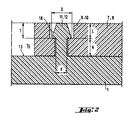
- FIG. 2 shows the enlarged representation of a through bore 9, 10 which interacts with a pin 11, 12.
- This through hole 9, 10 is of stepped design, the largest diameter of the through hole 9, 10 being arranged in the region of the large-area head 1 pointing counter to the setting direction.
- the pin 11, 12 projecting essentially vertically from the bottom 13 of the recess 14 has a step-like extension 18, which in turn tapers conically towards the free end of the pin 11, 12.
- the distance A between the step of the step-like extension 18 and the bottom 13, from which the pin 11, 12 protrudes corresponds essentially to the wall thickness of the cover parts 7, 8, reduced by the depth T of that area of the through hole 9, 10 with the larger one Diameter.
- the tapering region of the pin 11, 12 extends over a length L, which essentially corresponds to the depth T of that region of the through hole 9, 10 which has the larger diameter.
- the closest diameter D of the pin 11, 12 is larger than that part of the through hole 9, 10 with the smaller diameter d.
- the wall thickness of the large-area head 1 decreases towards its outer contour.
Abstract
Description
Die Erfindung betrifft eine Vorrichtung zum Befestigen von Isolationselementen an einem Bauteil, gemäss dem Oberbegriff des Patentanspruchs 1.The invention relates to a device for fastening insulation elements to a component, according to the preamble of
Dem Befestigen von plattenförmigen Isolationselementen an Bauteilen dienen Vorrichtungen, wie sie beispielsweise aus der US-PS 5,118,235 bekannt sind. Diese bekannte Vorrichtung weist einen grossflächigen Kopf und einen vom Kopf abragenden Hohlschaft auf. In einen Innenraum des Hohlschaftes ist über eine im grossflächigen Kopf angeordnete Öffnung ein Befestigungselement einsetzbar, das mittels eines geeigneten Werkzeuges in das Bauteil eintreibbar ist. Im gesetzten Zustand stützt sich das Befestigungselement an einer im Innenraum angeordneten, entgegen der Setzrichtung weisenden Schulter des Hohlschaftes ab und durchsetzt den setzrichtungsseitigen Endbereich des Hohlschaftes.Devices such as are known, for example, from US Pat. No. 5,118,235 are used to fasten plate-shaped insulation elements to components. This known device has a large-area head and a hollow shaft protruding from the head. A fastening element, which can be driven into the component by means of a suitable tool, can be inserted into an interior of the hollow shaft via an opening arranged in the large-area head. In the set state, the fastening element is supported on a shoulder of the hollow shaft which is arranged in the interior and points against the setting direction and penetrates the end region of the hollow shaft on the setting direction.
Auf die Isolationselemente wird Putzmaterial aufgetragen. Dabei ist es wichtig dass kein Putzmaterial in den Innenraum des Hohlschaftes gelangen kann, da dies zu Vertiefungen an der Oberfläche der aufgetragenen Putzschicht führt. Dringt Putzmaterial und damit auch Feuchtigkeit in den Innenraum des Hohlschaftes, so kann dies eine Korrosion an dem Befestigungselement hervorrufen, wenn dieses nicht aus rostfreiem Material besteht.Plaster material is applied to the insulation elements. It is important that no cleaning material can get into the interior of the hollow shaft, as this leads to depressions on the surface of the applied layer of plaster. If cleaning material and thus moisture penetrates into the interior of the hollow shaft, this can cause corrosion on the fastening element if it is not made of rustproof material.
Damit kein Putzmaterial in den Innenraum des Hohlschaftes gelangen kann, ist die Öffnung mittels eines Deckels verschliessbar. Dieser Deckel ist ausserhalb der Öffnung um eine Gelenkachse schwenkbar an dem grossflächigen Kopf angeordnet und wirkt in der geschlossenen Stellung mit einem Vorsprung zusammen, der von der parallel zur Längsachse des Hohlschaftes verlaufenden Innenwand des Hohlschaftes abragt. In der geschlossenen Stellung liegt der Deckel mit seiner entgegen der Setzrichtung weisenden Seite an der dem Innenraum zugewandten Anschlagkante des Vorsprungs an.So that no cleaning material can get into the interior of the hollow shaft, the opening can be closed by means of a cover. This cover is arranged on the large-area head so as to be pivotable about an articulation axis and, in the closed position, cooperates with a projection which protrudes from the inner wall of the hollow shaft, which runs parallel to the longitudinal axis of the hollow shaft. In the closed position, the cover, with its side pointing counter to the setting direction, lies against the stop edge of the projection facing the interior.
Der Deckel kann beim Verschliessen der Öffnung oder beim Auftragen von Putzmaterial derart weit in den Innenraum hineingedrückt bzw. verschwenkt werden, dass die Öffnung nicht mehr verschlossen ist und dadurch Putzmaterial in den Innenraum des Hohlschaftes gelangen kann.When closing the opening or when applying cleaning material, the cover can be pressed or pivoted so far into the interior that the opening is no longer closed and cleaning material can thus get into the interior of the hollow shaft.
Der Erfindung liegt die Aufgabe zugrunde, eine Vorrichtung zum Befestigen von Isolationselementen zu schaffen, bei der sichergestellt ist, dass beim Einwirken von Kräften, hervorgerufen durch die Handhabung oder das Auftragen von Putzmaterial, der Deckel sicher geschlossen bleibt.The invention has for its object to provide a device for attaching insulation elements, in which it is ensured that the force of forces caused by the handling or application of cleaning material, the lid remains securely closed.
Die Lösung dieser Aufgabe erfolgt durch eine Vorrichtung, welche die im kennzeichnenden Abschnitt des Patentanspruchs 1 angeführten Merkmale aufweist.This object is achieved by a device which has the features stated in the characterizing section of
Die parallel zur Querschnittsfläche des Hohlschaftes verlaufende Fläche, an der der Vorsprung angeordnet ist, dient als Anschlagfläche für den Deckel, damit dieser aus der geschlossenen Stellung nicht weiter in den Innenraum des Hohlschaftes gedrückt werden kann. Die Anordnung des Vorsprunges an der Anschlagfläche ermöglicht ein einfaches und sicheres Zusammenwirken mit dem Deckel, wenn dieser in die geschlossene Stellung bewegt wird.The surface running parallel to the cross-sectional area of the hollow shaft, on which the projection is arranged, serves as a stop surface for the cover so that it cannot be pressed further into the interior of the hollow shaft from the closed position. The arrangement of the projection on the stop surface enables simple and safe interaction with the cover when it is moved into the closed position.
Damit der Deckel in der geschlossenen Stellung die der Setzrichtung abgewandte Oberfläche des grossflächigen Kopfes nicht überragt, ist vorzugsweise die Fläche von einem die Öffnung wenigstens teilweise umgebenden Boden einer im Kopf angeordneten, den Deckel in der geschlossenen Stellung aufnehmenden Vertiefung gebildet.So that the cover in the closed position does not protrude beyond the surface of the large-area head facing away from the setting direction, the surface is preferably formed by a bottom at least partially surrounding the opening of a recess arranged in the head and receiving the cover in the closed position.
Aus herstelltechnischen Gründen ist zweckmässigerweise der an dem Boden angeordnete Vorsprung als im wesentlichen senkrecht von dem Boden abragender Zapfen ausgebildet, der in einer am Deckel angeordneten Durchgangsbohrung einrastbar ist.For manufacturing reasons, the projection arranged on the bottom is expediently designed as a pin projecting essentially perpendicularly from the bottom, which can be snapped into a through hole arranged on the cover.
Eine unlösbare Verbindung zwischen dem Zapfen und dem Deckel wird vorteilhafterweise erreicht, indem sich der Zapfen entgegen der Setzrichtung stufenförmig erweitert und zu seinem freien Ende hin konisch verjüngt, wobei der grösste Durchmesser des Zapfens grösser ist als der Durchmesser der Durchgangsbohrung. Die Wandstärke des mit dem Zapfen zusammenwirkenden Deckels kann beispielsweise wenigstens im Bereich der Durchgangsbohrung dem Abstand zwischen der Stufe der stufenförmigen Erweiterung und dem Boden der Vertiefung entsprechen.An inseparable connection between the pin and the cover is advantageously achieved by the pin widening stepwise against the setting direction and tapering conically towards its free end, the largest diameter of the pin being larger than the diameter of the through hole. The wall thickness of the cover cooperating with the pin can correspond, for example, at least in the area of the through hole to the distance between the step of the step-like expansion and the bottom of the depression.
Um das dem Eintreiben des Befestigungselementes dienende Werkzeug besser in den Hohlschaft einführen zu können, ist zweckmässigerweise der Deckel zweiteilig ausgebildet, wobei die Deckelteile ausserhalb der Öffnung angelenkt und um parallel zueinander verlaufende Gelenkachsen schwenkbar sind. Die einander in der geöffneten Stellung zugewandten Seiten der Deckelteile dienen dabei als Zentrierhilfe beim Einsetzen des Werkzeugs.In order to be able to better insert the tool used to drive in the fastening element into the hollow shaft, the cover is expediently formed in two parts, the cover parts being articulated outside the opening and pivotable about joint axes running parallel to one another. The sides of the cover parts facing each other in the open position serve as a centering aid when inserting the tool.
Die entgegen der Setzrichtung weisenden Seiten der Deckelteile können beispielsweise mit einer Profilierung versehen sein, die eine besser Haftung des Putzmaterials gewährleistet. Eine bessere Haftung bedeutet auch, dass Zugkräfte auf die Deckelteile einwirken können. Damit diese Deckelteile auch beim Auftreten von Zugkräften sicher in der geschlossenen Stellung verbleiben, sind vorzugsweise an dem Boden wenigstens zwei Zapfen angeordnet und jedes Deckelteil weist wenigtens eine Durchgangsbohrung auf, in die ein Zapfen einrastbar ist.The sides of the cover parts pointing counter to the setting direction can, for example, be provided with a profile which ensures better adhesion of the cleaning material. Better adhesion also means that tensile forces can act on the cover parts. So that these cover parts remain securely in the closed position even when tensile forces occur, at least two pegs are preferably arranged on the base and each cover part has at least one through hole into which a peg can be latched.
Beim Verschliessen der Öffnung ist es unwesentlich, welcher der beiden Deckelteile zuerst die geschlossene Stellung einnimmt. Es können daher auch beide Deckelteile gleichzeitig in die geschlossene Stellung verschwenkt werden.When the opening is closed, it is immaterial which of the two cover parts is in the closed position first. Both cover parts can therefore also be pivoted into the closed position at the same time.
Die Erfindung wird anhand von Zeichnungen, die ein Ausführungsbeispiel wiedergeben, näher erläutert. Es zeigen:
- Fig.1
- Eine erfindungsgemässe Vorrichtung zum Befestigen von Isolationselementen, teilweise geschnitten;
- Fig. 2
- Eine vergrösserte Darstellung der formschlüssigen Verbindung, zwischen einem Zapfen und einer Durchgangsbohrung eines Deckelteils.
- Fig. 1
- A device according to the invention for fastening insulation elements, partially cut;
- Fig. 2
- An enlarged view of the positive connection between a pin and a through hole of a cover part.
Die in Fig. 1 dargestellte Vorrichtung dient der Befestigung von nicht dargestellten Isolationselementen an einem ebenfalls nicht dargestellten Bauteil und setzt sich aus einem grossflächigen Kopf 1 und einem sich daran anschliessenden Hohlschaft 2 zusammen. Der Hohlschaft 2 weist einen Innenraum 4 auf, der durch eine im Bereich des grossflächigen Kopfes 1 angeordnete Öffnung 15 von aussen zugänglich ist und der der Aufnahme eines Befestigungselementes 3 dient, mit dem die Vorrichtung an dem Bauteil festlegbar ist. Eine im Innenraum 4 des Hohlschaftes 2 angeordnete, entgegen der Setzrichtung weisende Anschlagfläche 5 dient als Widerlager für einen radial erweiterten Bereich 6 des Befestigungselementes 3.The device shown in Fig. 1 is used to attach insulation elements, not shown, to a component, also not shown, and is composed of a large-
Damit nicht dargestelltes Putzmaterial, das auf die befestigten Isolationselemente aufgetragen wird, nicht in den Innenraum 4 des Hohlschaftes 2 gelangen kann, ist die Öffnung 15 mittels zweier Deckelteile 7, 8 eines Deckels verschliessbar, die in der geschlossenen Stellung in einer einen Boden 13 aufweisenden Vertiefung 14 des Kopfes 1 versenkt angeordnet sind. Dabei wirken jeweils zwei Durchgangsbohrungen 9, 10 jedes Deckelteils 7, 8 mit jeweils zwei vom Boden 13 abragen Zapfen 11, 12 zusammen.So that cleaning material, not shown, which is applied to the attached insulation elements, cannot get into the interior 4 of the
Beide Deckelteile 7, 8 sind um ausserhalb der Öffnung 15 liegende Gelenkachsen 16, 17 schwenkbar an dem grossflächigen Kopf 1 angeordnet. Die Projektionsfläche der Vertiefung 14 erstreckt sich um die Öffnung 15 und hat eine im wesentlichen quadratische Form. Die Gelenkachsen 16, 17 erstrecken sich entlang zweier einander gegenüberliegender Seiten dieser Vertiefung 14. Die parallel zur Gelenkachse 16, 17 gemessene Länge der Deckelteile 7, 8 entspricht im wesentlichen einer Seitenlänge der Vertiefung 14. Die senkrecht zur Gelenkachse 16, 17 gemessen Länge der Deckelteile 7, 8 entspricht im wesentlichen der halben Seitenlänge der Vertiefung 14. Die Wandstärke der Deckelteile 7, 8 ist im wesentlichen auf die Tiefe der Vertiefung 14 abgestimmt.Both cover parts 7, 8 are arranged on the large-
In der Fig. 2 ist die vergrösserte Darstellung einer mit einem Zapfen 11, 12 zusammenwirkenden Durchgangsbohrung 9, 10 dargestellt. Diese Durchgangsbohrung 9, 10 ist stufenförmig ausgebildet, wobei der grösste Durchmesser der Durchgangsbohrung 9, 10 in dem entgegen der Setzrichtung weisenden Bereich des grossflächigen Kopfes 1 angeordnet ist.FIG. 2 shows the enlarged representation of a
Der von dem Boden 13 der Vertiefung 14 im wesentlichen senkrecht abragende Zapfen 11, 12 weist eine stufenförmige Erweiterung 18 auf, die sich zum freien Ende des Zapfens 11, 12 hin wiederum konisch verjüngt. Der Abstand A zwischen der Stufe der stufenförmigen Erweiterung 18 und dem Boden 13, von dem der Zapfen 11, 12 abragt, entspricht im wesentlichen der Wandstärke der Deckelteile 7, 8, reduziert um die Tiefe T jenes Bereiches der Durchgangsbohrung 9, 10 mit dem grösseren Durchmesser. Der sich verjüngende Bereich des Zapfens 11, 12 erstreckt sich über eine Länge L, die im wesentlichen der Tiefe T jenes Bereiches der Durchgangsbohrung 9, 10 entspricht, die den grösseren Durchmesser aufweist. Der gässte Durchmesser D des Zapfens 11, 12 ist grössser ausgebildet als jener Teil der Durchgangsbohrung 9, 10 mit dem kleineren Durchmesser d.The
Beim Verschliessen der Öffnung 15 werden die Deckelteile 7, 8 verschwenkt. Dabei gelangen die konischen Verjüngungen der ausserhalb der Öffnung 15 angeordneten Zapfen 11, 12 mit den Mündungsbereichen der Durchgangsbohrungen 9, 10 der Deckelteile 7, 8 in Berührung. Beim weiteren Verschwenken der Deckelteile 7, 8 wird der radial elastische, den grössten Durchmesser D des Zapfens 11,12 aufweisende Bereich radial zusammengedrückt. Wenn die Deckelteile 7, 8 die geschlossene Stellung erreichen, wirkt der zusammengedrückte Bereich des Zapfens 11, 12 nicht mehr mit dem kleineren Durchmesser d der Durchgangsbohrungen 7, 8 zusammen und kann sich daher wieder ausdehnen. Somit entsteht eine formschlüssige Verbindung zwischen den Zapfen 11, 12 und den Deckelteilen 7, 8.When the opening 15 is closed, the cover parts 7, 8 are pivoted. The conical tapering of the
Die Wandstärke des grossflächigen Kopfes 1 nimmt zu dessen Aussenkontur hin ab.The wall thickness of the large-
Claims (6)
Applications Claiming Priority (2)
| Application Number | Priority Date | Filing Date | Title |
|---|---|---|---|
| DE19619318 | 1996-05-14 | ||
| DE19619318A DE19619318A1 (en) | 1996-05-14 | 1996-05-14 | Insulation fastener |
Publications (3)
| Publication Number | Publication Date |
|---|---|
| EP0807722A2 true EP0807722A2 (en) | 1997-11-19 |
| EP0807722A3 EP0807722A3 (en) | 2000-08-02 |
| EP0807722B1 EP0807722B1 (en) | 2003-06-18 |
Family
ID=7794224
Family Applications (1)
| Application Number | Title | Priority Date | Filing Date |
|---|---|---|---|
| EP97810206A Expired - Lifetime EP0807722B1 (en) | 1996-05-14 | 1997-04-09 | Insulation fixing means |
Country Status (5)
| Country | Link |
|---|---|
| US (1) | US5779421A (en) |
| EP (1) | EP0807722B1 (en) |
| AT (1) | ATE243288T1 (en) |
| CA (1) | CA2204938C (en) |
| DE (2) | DE19619318A1 (en) |
Cited By (3)
| Publication number | Priority date | Publication date | Assignee | Title |
|---|---|---|---|---|
| EP0959198A1 (en) * | 1998-05-18 | 1999-11-24 | Berner GmbH | Insulating panel holder |
| EP1050690A3 (en) * | 1999-05-07 | 2002-04-17 | HILTI Aktiengesellschaft | Fastening device for insulating panels |
| RU172001U1 (en) * | 2017-01-30 | 2017-06-26 | Виталий Евгеньевич Чекалин | FASTENING ELEMENT |
Families Citing this family (6)
| Publication number | Priority date | Publication date | Assignee | Title |
|---|---|---|---|---|
| US6513301B1 (en) | 1999-10-20 | 2003-02-04 | Robert Snyder | Method of and instrument or arrangement for installing thermal insulation sheets in confined areas |
| WO2006019786A1 (en) * | 2004-07-19 | 2006-02-23 | James Murtha | Preset depth adapter and finger guard for screws and nails when installing sheetrock |
| DE202007010563U1 (en) | 2007-07-27 | 2007-11-15 | Kew Kunststofferzeugnisse Gmbh Wilthen | fastener |
| DE102008041036A1 (en) * | 2008-08-06 | 2010-02-11 | Hilti Aktiengesellschaft | Nail-shaped fastening element |
| KR101077844B1 (en) * | 2011-04-29 | 2011-11-07 | 김재옥 | Stone corbel for support device |
| US10228007B2 (en) * | 2015-12-09 | 2019-03-12 | Illinois Tool Works Inc. | Panel fastener |
Citations (6)
| Publication number | Priority date | Publication date | Assignee | Title |
|---|---|---|---|---|
| DE3045986A1 (en) * | 1980-12-05 | 1982-06-09 | Adolf Böhl Schrauben- und Kunststoffwerk GmbH & Co, 5920 Bad Berleburg | Heat insulating external wall panel fixing element - has covering plate engaging tie bolt or pressure plate on support structure and closing panel cavity |
| DE3244839A1 (en) * | 1982-12-03 | 1984-06-07 | Achim Ing.(grad.) 8000 München Hirsemann | Insulation material retainer |
| US4884932A (en) * | 1987-05-01 | 1989-12-05 | Meyer Eugene M | Decking insulation fastener |
| US5118235A (en) * | 1991-02-11 | 1992-06-02 | Illinois Tool Works Inc. | Washer with integral flap and fastening assembly combining fastener with such washer |
| DE9311122U1 (en) * | 1993-07-26 | 1993-10-07 | Ejot Kunststofftech Gmbh | Fastening element and setting tool for such a fastening element |
| EP0658667A1 (en) * | 1993-12-16 | 1995-06-21 | "TOGE-DÜBEL" A. Gerhard GmbH | Metallic dowel of an insulation anchor |
Family Cites Families (4)
| Publication number | Priority date | Publication date | Assignee | Title |
|---|---|---|---|---|
| DE4041819A1 (en) * | 1990-12-24 | 1992-06-25 | Hilti Ag | FASTENING ELEMENT FOR INSULATION PANELS |
| US5607272A (en) * | 1995-01-06 | 1997-03-04 | Illinois Tool Works Inc. | Attachment plate for insulation panels |
| DE19504463A1 (en) * | 1995-02-10 | 1996-08-14 | Hilti Ag | Fastening element for insulation materials |
| US5626451A (en) * | 1995-10-12 | 1997-05-06 | Wind-Lock Corporation | Washer for use with exterior insulation |
-
1996
- 1996-05-14 DE DE19619318A patent/DE19619318A1/en not_active Ceased
-
1997
- 1997-04-09 AT AT97810206T patent/ATE243288T1/en active
- 1997-04-09 EP EP97810206A patent/EP0807722B1/en not_active Expired - Lifetime
- 1997-04-09 DE DE59710293T patent/DE59710293D1/en not_active Expired - Lifetime
- 1997-05-09 CA CA002204938A patent/CA2204938C/en not_active Expired - Fee Related
- 1997-05-13 US US08/855,348 patent/US5779421A/en not_active Expired - Lifetime
Patent Citations (6)
| Publication number | Priority date | Publication date | Assignee | Title |
|---|---|---|---|---|
| DE3045986A1 (en) * | 1980-12-05 | 1982-06-09 | Adolf Böhl Schrauben- und Kunststoffwerk GmbH & Co, 5920 Bad Berleburg | Heat insulating external wall panel fixing element - has covering plate engaging tie bolt or pressure plate on support structure and closing panel cavity |
| DE3244839A1 (en) * | 1982-12-03 | 1984-06-07 | Achim Ing.(grad.) 8000 München Hirsemann | Insulation material retainer |
| US4884932A (en) * | 1987-05-01 | 1989-12-05 | Meyer Eugene M | Decking insulation fastener |
| US5118235A (en) * | 1991-02-11 | 1992-06-02 | Illinois Tool Works Inc. | Washer with integral flap and fastening assembly combining fastener with such washer |
| DE9311122U1 (en) * | 1993-07-26 | 1993-10-07 | Ejot Kunststofftech Gmbh | Fastening element and setting tool for such a fastening element |
| EP0658667A1 (en) * | 1993-12-16 | 1995-06-21 | "TOGE-DÜBEL" A. Gerhard GmbH | Metallic dowel of an insulation anchor |
Cited By (3)
| Publication number | Priority date | Publication date | Assignee | Title |
|---|---|---|---|---|
| EP0959198A1 (en) * | 1998-05-18 | 1999-11-24 | Berner GmbH | Insulating panel holder |
| EP1050690A3 (en) * | 1999-05-07 | 2002-04-17 | HILTI Aktiengesellschaft | Fastening device for insulating panels |
| RU172001U1 (en) * | 2017-01-30 | 2017-06-26 | Виталий Евгеньевич Чекалин | FASTENING ELEMENT |
Also Published As
| Publication number | Publication date |
|---|---|
| US5779421A (en) | 1998-07-14 |
| EP0807722B1 (en) | 2003-06-18 |
| CA2204938A1 (en) | 1997-11-14 |
| CA2204938C (en) | 2001-10-30 |
| DE19619318A1 (en) | 1997-11-20 |
| ATE243288T1 (en) | 2003-07-15 |
| EP0807722A3 (en) | 2000-08-02 |
| DE59710293D1 (en) | 2003-07-24 |
Similar Documents
| Publication | Publication Date | Title |
|---|---|---|
| EP0086937B1 (en) | Detachable junction of two panels perpendicular to one another, especially furniture panels | |
| DE3304569C1 (en) | Device for adjusting a first component relative to a second component | |
| DE3833040C2 (en) | ||
| EP3526476B1 (en) | Floatingly mounted clip | |
| EP0807722A2 (en) | Insulation fixing mean | |
| DE4228383A1 (en) | Ball joint for connecting piston cylinder units to structures - has specially designed socket to receive ball head with access for screwdriver and with secure engagement even under great force. | |
| DE3348339C2 (en) | ||
| EP0539687B1 (en) | Perpendicular joint for profiled bars with lengthwise grooves | |
| EP1666688B1 (en) | Hinge for windows, doors and the like | |
| WO2021052840A1 (en) | Fastening element and component arrangement with fastening element and fastening method | |
| EP0166111B1 (en) | Electronic control unit | |
| DE3346067C2 (en) | ||
| EP1013944A2 (en) | Fastening element | |
| DE2656958B2 (en) | Corner connection of mitered profiles of a window frame, door frame or the like | |
| EP0454940B1 (en) | Connecting means for frame and post | |
| DE19629180B4 (en) | Insulation fastener | |
| EP0297053A1 (en) | Dowel assembly | |
| EP0166982A1 (en) | Connecting device to construct a multidimensional construction | |
| DE3632026C2 (en) | ||
| DE10144982C2 (en) | fastener | |
| DE19629179B4 (en) | Insulation fastener | |
| DE868810C (en) | Nail tip for bending the tip of the nail when driving it in | |
| DE102009010832B4 (en) | Mounting device and method of assembly for door and / or window frames | |
| DE19532456C2 (en) | Connector for wooden parts | |
| EP0569743B1 (en) | Cover body |
Legal Events
| Date | Code | Title | Description |
|---|---|---|---|
| PUAI | Public reference made under article 153(3) epc to a published international application that has entered the european phase |
Free format text: ORIGINAL CODE: 0009012 |
|
| AK | Designated contracting states |
Kind code of ref document: A2 Designated state(s): AT DE FR GB NL |
|
| PUAL | Search report despatched |
Free format text: ORIGINAL CODE: 0009013 |
|
| AK | Designated contracting states |
Kind code of ref document: A3 Designated state(s): AT DE FR GB NL |
|
| 17P | Request for examination filed |
Effective date: 20010202 |
|
| GRAH | Despatch of communication of intention to grant a patent |
Free format text: ORIGINAL CODE: EPIDOS IGRA |
|
| RTI1 | Title (correction) |
Free format text: INSULATION FIXING MEANS |
|
| GRAH | Despatch of communication of intention to grant a patent |
Free format text: ORIGINAL CODE: EPIDOS IGRA |
|
| GRAA | (expected) grant |
Free format text: ORIGINAL CODE: 0009210 |
|
| AK | Designated contracting states |
Designated state(s): AT DE FR GB NL |
|
| REG | Reference to a national code |
Ref country code: GB Ref legal event code: FG4D Free format text: NOT ENGLISH |
|
| REF | Corresponds to: |
Ref document number: 59710293 Country of ref document: DE Date of ref document: 20030724 Kind code of ref document: P |
|
| GBT | Gb: translation of ep patent filed (gb section 77(6)(a)/1977) |
Effective date: 20031021 |
|
| ET | Fr: translation filed | ||
| PLBE | No opposition filed within time limit |
Free format text: ORIGINAL CODE: 0009261 |
|
| STAA | Information on the status of an ep patent application or granted ep patent |
Free format text: STATUS: NO OPPOSITION FILED WITHIN TIME LIMIT |
|
| 26N | No opposition filed |
Effective date: 20040319 |
|
| PGFP | Annual fee paid to national office [announced via postgrant information from national office to epo] |
Ref country code: AT Payment date: 20120327 Year of fee payment: 16 |
|
| PGFP | Annual fee paid to national office [announced via postgrant information from national office to epo] |
Ref country code: DE Payment date: 20130314 Year of fee payment: 17 Ref country code: GB Payment date: 20130403 Year of fee payment: 17 |
|
| PGFP | Annual fee paid to national office [announced via postgrant information from national office to epo] |
Ref country code: FR Payment date: 20130625 Year of fee payment: 17 Ref country code: NL Payment date: 20130410 Year of fee payment: 17 |
|
| REG | Reference to a national code |
Ref country code: DE Ref legal event code: R119 Ref document number: 59710293 Country of ref document: DE |
|
| REG | Reference to a national code |
Ref country code: NL Ref legal event code: V1 Effective date: 20141101 |
|
| REG | Reference to a national code |
Ref country code: AT Ref legal event code: MM01 Ref document number: 243288 Country of ref document: AT Kind code of ref document: T Effective date: 20140409 |
|
| GBPC | Gb: european patent ceased through non-payment of renewal fee |
Effective date: 20140409 |
|
| REG | Reference to a national code |
Ref country code: FR Ref legal event code: ST Effective date: 20141231 |
|
| REG | Reference to a national code |
Ref country code: DE Ref legal event code: R119 Ref document number: 59710293 Country of ref document: DE Effective date: 20141101 |
|
| PG25 | Lapsed in a contracting state [announced via postgrant information from national office to epo] |
Ref country code: DE Free format text: LAPSE BECAUSE OF NON-PAYMENT OF DUE FEES Effective date: 20141101 Ref country code: GB Free format text: LAPSE BECAUSE OF NON-PAYMENT OF DUE FEES Effective date: 20140409 |
|
| PG25 | Lapsed in a contracting state [announced via postgrant information from national office to epo] |
Ref country code: AT Free format text: LAPSE BECAUSE OF NON-PAYMENT OF DUE FEES Effective date: 20140409 Ref country code: NL Free format text: LAPSE BECAUSE OF NON-PAYMENT OF DUE FEES Effective date: 20141101 Ref country code: FR Free format text: LAPSE BECAUSE OF NON-PAYMENT OF DUE FEES Effective date: 20140430 |