EP0734698A2 - Stent for transluminal implantation into hollow organs - Google Patents
Stent for transluminal implantation into hollow organs Download PDFInfo
- Publication number
- EP0734698A2 EP0734698A2 EP96104982A EP96104982A EP0734698A2 EP 0734698 A2 EP0734698 A2 EP 0734698A2 EP 96104982 A EP96104982 A EP 96104982A EP 96104982 A EP96104982 A EP 96104982A EP 0734698 A2 EP0734698 A2 EP 0734698A2
- Authority
- EP
- European Patent Office
- Prior art keywords
- stent
- tubular body
- openings
- longitudinal axis
- shaped
- Prior art date
- Legal status (The legal status is an assumption and is not a legal conclusion. Google has not performed a legal analysis and makes no representation as to the accuracy of the status listed.)
- Granted
Links
Images


Classifications
-
- A—HUMAN NECESSITIES
- A61—MEDICAL OR VETERINARY SCIENCE; HYGIENE
- A61F—FILTERS IMPLANTABLE INTO BLOOD VESSELS; PROSTHESES; DEVICES PROVIDING PATENCY TO, OR PREVENTING COLLAPSING OF, TUBULAR STRUCTURES OF THE BODY, e.g. STENTS; ORTHOPAEDIC, NURSING OR CONTRACEPTIVE DEVICES; FOMENTATION; TREATMENT OR PROTECTION OF EYES OR EARS; BANDAGES, DRESSINGS OR ABSORBENT PADS; FIRST-AID KITS
- A61F2/00—Filters implantable into blood vessels; Prostheses, i.e. artificial substitutes or replacements for parts of the body; Appliances for connecting them with the body; Devices providing patency to, or preventing collapsing of, tubular structures of the body, e.g. stents
- A61F2/82—Devices providing patency to, or preventing collapsing of, tubular structures of the body, e.g. stents
- A61F2/86—Stents in a form characterised by the wire-like elements; Stents in the form characterised by a net-like or mesh-like structure
- A61F2/90—Stents in a form characterised by the wire-like elements; Stents in the form characterised by a net-like or mesh-like structure characterised by a net-like or mesh-like structure
- A61F2/91—Stents in a form characterised by the wire-like elements; Stents in the form characterised by a net-like or mesh-like structure characterised by a net-like or mesh-like structure made from perforated sheet material or tubes, e.g. perforated by laser cuts or etched holes
- A61F2/915—Stents in a form characterised by the wire-like elements; Stents in the form characterised by a net-like or mesh-like structure characterised by a net-like or mesh-like structure made from perforated sheet material or tubes, e.g. perforated by laser cuts or etched holes with bands having a meander structure, adjacent bands being connected to each other
- A61F2002/9155—Adjacent bands being connected to each other
- A61F2002/91558—Adjacent bands being connected to each other connected peak to peak
-
- A—HUMAN NECESSITIES
- A61—MEDICAL OR VETERINARY SCIENCE; HYGIENE
- A61F—FILTERS IMPLANTABLE INTO BLOOD VESSELS; PROSTHESES; DEVICES PROVIDING PATENCY TO, OR PREVENTING COLLAPSING OF, TUBULAR STRUCTURES OF THE BODY, e.g. STENTS; ORTHOPAEDIC, NURSING OR CONTRACEPTIVE DEVICES; FOMENTATION; TREATMENT OR PROTECTION OF EYES OR EARS; BANDAGES, DRESSINGS OR ABSORBENT PADS; FIRST-AID KITS
- A61F2230/00—Geometry of prostheses classified in groups A61F2/00 - A61F2/26 or A61F2/82 or A61F9/00 or A61F11/00 or subgroups thereof
- A61F2230/0002—Two-dimensional shapes, e.g. cross-sections
- A61F2230/0004—Rounded shapes, e.g. with rounded corners
- A61F2230/0013—Horseshoe-shaped, e.g. crescent-shaped, C-shaped, U-shaped
Definitions
- the tubular body 1 Due to the structure of the tubular body 1 according to the invention, a high degree of flexibility is achieved both in the compressed and in the expanded state, so that implantation in curved hollow organs as well as in hollow organs arranged in the region of joints is possible. A kinking of the stent by bending the joints is largely ruled out due to the high flexibility achieved.
- the structure designed according to the invention ensures good longitudinal and transverse stability of the stent both in the compressed and in the expanded state.
- the longitudinal components 20 are arranged obliquely to the longitudinal axis 2 of the stent. This creates a spiral arrangement of the longitudinal components 20 around the longitudinal axis 2 of the stent. This spiral arrangement on the one hand increases the elastic positioning forces of the longitudinal components 20, so that the stability of the stent in the expanded state can be further improved.
- a sheath arranged on the outside of the stent, with which the stent is held in the compressed state when inserted, can easily be pulled back onto the already partially expanded stent due to the spiral arrangement of the longitudinal components 20, so that if the stent is unsatisfactorily positioned Stent can be repositioned.
Abstract
Description
Die vorliegende Erfindung betrifft einen Stent zur transluminalen Implantation in Hohlorgane, insbesondere in Blutgefäße, Harnleiter, Speiseröhren oder Gallenwege mit einem im wesentlichen röhrenförmigen Körper, der von einem komprimierten Zustand mit einem ersten Querschnittsdurchmesser in einen expandierten Zustand mit einem vergrößerten zweiten Querschnittsdurchmesser überführbar ist, wobei die Wand des röhrenförmigen Körpers sich sowohl in Längsrichtung als auch in Umfangsrichtung des Stents wiederholende, die Expansion gewährleistende Durchbrechungen aufweist.The present invention relates to a stent for transluminal implantation in hollow organs, in particular in blood vessels, ureters, esophagus or biliary tract, with an essentially tubular body which can be converted from a compressed state with a first cross-sectional diameter to an expanded state with an enlarged second cross-sectional diameter the wall of the tubular body has repetitive openings in the longitudinal direction as well as in the circumferential direction of the stent, which ensure expansion.
Stents dieser Art werden zur Rekanalisation von krankhaft veränderten Hohlorganen eingesetzt. Dabei werden die Stents im komprimierten Zustand über einen Einführkatheter an die zu behandelnde Stelle innerhalb des Hohlorgans eingeführt, wo sie durch unterschiedliche Maßnahmen auf einen Durchmesser, der dem des gesunden Hohlorgans entspricht, expandiert werden können, so daß eine Stützwirkung des Hohlorgans, beispielsweise einer Gefäßwand, erreicht wird.Stents of this type are used for the recanalization of pathologically modified hollow organs. The stents are inserted in the compressed state via an insertion catheter to the site to be treated within the hollow organ, where they can be expanded to a diameter corresponding to that of the healthy hollow organ by various measures, so that the hollow organ has a supporting effect, for example a vessel wall , is achieved.
Je nachdem, auf welche Weise der expandierte Zustand erreicht wird, unterscheidet man zwischen ballonexpandierten Stents und selbstexpandierenden Stents. Ballonexpandierte Stents werden im komprimierten Zustand auf einen speziellen Ballonkatheter montiert, bis zu der zu behandelnden Stelle des jeweiligen Hohlorgans eingeführt und dort durch Balloninsufflation auf den gewünschten Durchmesser ausgedehnt. Durch die plastische Verformung des Stentmaterials erhält der Stent im expandierten Zustand seine Stabilität, so daß eine ausreichende Stützwirkung des Hohlorgans erzielt wird.Depending on how the expanded state is achieved, a distinction is made between balloon-expanded stents and self-expanding stents. Balloon-expanded stents are mounted in a compressed state on a special balloon catheter, inserted up to the site of the respective hollow organ to be treated and expanded there to the desired diameter by balloon insufflation. The plastic deformation of the stent material gives the stent its stability in the expanded state, so that a sufficient supporting effect of the hollow organ is achieved.
Selbstexpandierende Stents werden durch Hilfsmittel, wie beispielsweise membranartige Überzüge in ihrem komprimierten Zustand gehalten und über einen Katheter an die zu behandelnde Stelle innerhalb des Hohlorgans eingeführt. Nach Entfernen des Überzugs dehnen sich diese Stents durch ihre eigene Spannung von selbst auf einen vorbestimmten Durchmesser im Hohlorgan aus, so daß auf diese Weise die Stützung der Wand des Hohlorgans erreicht wird. Grundsätzlich können auch diese selbstexpandierenden Stents mit Hilfe eines Ballonkatheters an die Gefäßwand nachgedrückt werden.Self-expanding stents are kept in their compressed state by means of aids, such as, for example, membrane-like coatings, and are introduced via a catheter to the site to be treated within the hollow organ. After removal of the coating, these stents automatically expand to a predetermined diameter in the hollow organ, so that the wall of the hollow organ is supported in this way. In principle, these self-expanding stents can also be pressed against the vessel wall using a balloon catheter.
Zu der Gruppe der selbstexpandierenden Stents gehören auch Stents aus dem sogenannten "Memory-Metall" Nitinol. Nitinol ist eine Nickel-Titanium-Legierung mit temperaturabhängigem Formverhalten. Wird beispielsweise einem Nitinoldraht eine bestimmte Form eingeprägt und anschließend der Draht über eine bestimmte "Memory-Temperatur" erhitzt, so gewinnt dieser Draht ein "Erinnerungsvermögen" für diese Form. Kühlt man anschließend den so behandelten Draht wieder unter seine Konversionstemperatur ab, die von der Legierung und der Wärmebehandlung abhängig ist, so wird er weich und leicht verformbar. Bei einer erneuten Erwärmung über die Konversionstemperatur nimmt der Draht automatisch die eingeprägte Form wieder an.The group of self-expanding stents also includes stents made of the so-called “memory metal” nitinol. Nitinol is a nickel-titanium alloy with temperature-dependent shape behavior. If, for example, a certain shape is impressed on a nitinol wire and the wire is then heated to a certain "memory temperature", this wire gains a "memory" for this shape. If the wire treated in this way is then cooled again below its conversion temperature, which depends on the alloy and the heat treatment, it becomes soft and easily deformable. When heated again above the conversion temperature, the wire automatically resumes the embossed shape.
Selbstexpandierende Stents der eingangs genannten Art werden beispielsweise dadurch erzeugt, daß mit einem Laser in die Wand eines röhrenförmigen Körpers mit geringem Durchmesser parallel zu dessen Längsachse verlaufende Schlitze geschnitten werden. Diese Schlitze sind in Umfangsrichtung versetzt zueinander angeordnet, so daß bei einer Expansion des röhrenförmigen Körpers beispielsweise durch Balloninsufflation oder durch Erwärmung im Falle eines Stents aus Memory-Metall rautenförmige Durchbrechungen entstehen, deren Längsachsen ebenfalls parallel zur Längsachse des röhrenförmigen Körpers verlaufen.Self-expanding stents of the type mentioned at the outset are produced, for example, by cutting slots running into the wall of a tubular body with a small diameter parallel to its longitudinal axis with a laser. These slots are arranged offset to one another in the circumferential direction, so that when the tubular body expands, for example by balloon insufflation or by heating in the case of a stent made of memory metal, diamond-shaped openings are formed, the longitudinal axes of which are also parallel to the longitudinal axis of the tubular body run.
Stents dieser Art haben jedoch den Nachteil, daß sie zum einen sowohl im komprimierten als auch im expandierten Zustand eine geringe Flexibilität aufweisen, so daß zum einen das Einführen in gebogene Hohlorgane nur in begrenztem Umfang möglich ist und zum anderen in Gelenkbereichen eingesetzte Stents zum Abknicken neigen, was zur Verringerung oder zum Unterbrechen des Blutflusses in Blutgefäßen oder gar zum Durchstoßen der Gefäßwand führen kann.However, stents of this type have the disadvantage that they have low flexibility both in the compressed and in the expanded state, so that insertion into curved hollow organs is only possible to a limited extent on the one hand and stents used in articular areas tend to kink , which can lead to a reduction or interruption of blood flow in blood vessels or even to puncture of the vessel wall.
Darüber hinaus tritt durch die Expansion des Stents eine Verkürzung in Längsrichtung auf, die relativ unkontrolliert ist, so daß die Positionierung des Stents an einer bestimmten zu behandelnden Stelle innerhalb des Hohlorgans relativ schwierig sein kann.In addition, the expansion of the stent causes a shortening in the longitudinal direction, which is relatively uncontrolled, so that the positioning of the stent at a specific location within the hollow organ to be treated can be relatively difficult.
Das Problem der geringen Flexibilität wird bei einem bekannten Stent dieser Art dadurch gelöst, daß die Verbindung zwischen einzelnen in Längsrichtung des Stents benachbart angeordneten Rauten unterbrochen wird. Nachteilig an dieser Anordnung ist jedoch, daß die freien, spitzen Rautenenden insbesondere bei einer Verbiegung des Stents, wie sie beispielsweise bei einer Kurvenimplantation erfolgt, am äußeren Kurvenradius aus der Wand des Stents herausragen und am inneren Kurvenradius in den Innenbereich des Stents hineinragen. Dies hat zur Folge, daß Verletzungen der Wand des Hohlorgans und des Ballons eines verwendeten Ballonkatheters auftreten können. Dies sind Komplikationen, die in der Praxis nicht hingenommen werden dürfen.The problem of low flexibility is solved in a known stent of this type in that the connection between individual diamonds arranged in the longitudinal direction of the stent is interrupted. A disadvantage of this arrangement, however, is that the free, pointed rhombus ends protrude from the wall of the stent at the outer radius of the curve, in particular when the stent is bent, as occurs, for example, during a curve implantation, and protrude into the inner region of the stent at the inner radius of the curve. As a result, injuries to the wall of the hollow organ and the balloon of a balloon catheter used can occur. These are complications that cannot be tolerated in practice.
Der vorliegenden Erfindung liegt die Aufgabe zugrunde, einen Stent der eingangs genannten Art zu schaffen, der zum einen sowohl im komprimierten als auch im expandierten Zustand eine hohe Flexibilität aufweist, wobei gleichzeitig eine sichere, risikofreie Anwendung gewährleistet ist, und bei dem durch die Expansion keine Verkürzung auftritt, so daß eine einwandfreie Positionierung des Stents erreichbar ist.The present invention has for its object to provide a stent of the type mentioned, which on the one hand has a high degree of flexibility both in the compressed and in the expanded state, while at the same time a secure, risk-free use is guaranteed, and in which there is no shortening due to the expansion, so that a perfect positioning of the stent can be achieved.
Diese Aufgabe wird nach der Erfindung ausgehend von einem Stent der eingangs genannten Art dadurch gelöst, daß jede Durchbrechung zumindest einen Abschnitt aufweist, der sowohl im komprimierten als auch im expandierten Zustand des Stents schräg zu dessen Längsachse angeordnet ist.This object is achieved according to the invention on the basis of a stent of the type mentioned in the introduction in that each opening has at least one section which is arranged obliquely to its longitudinal axis both in the compressed and in the expanded state of the stent.
Überraschenderweise kann durch die schräge Anordnung der Durchbrechungen die Flexibilität des Stents sowohl im komprimierten als auch im expandierten Zustand gegenüber einem Stent mit im komprimierten Zustand parallel zur dessen Längsachse verlaufenden Durchbrechungen deutlich verbessert werden. Da somit auf das Durchtrennen der Verbindungen zwischen in Längsrichtung nebeneinander angeordneten Rauten verzichtet werden kann, existieren bei einem erfindungsgemäß ausgebildeten Stent keinerlei scharfe Kanten, die Verletzungen der Wand des Hohlorgans oder eines Ballons eines Ballonkatheters verursachen könnten.Surprisingly, the oblique arrangement of the perforations can significantly improve the flexibility of the stent both in the compressed and in the expanded state compared to a stent with openings running parallel to the longitudinal axis of the stent in the compressed state. Since it is thus possible to dispense with the severing of the connections between diamonds arranged next to one another in the longitudinal direction, there are no sharp edges in a stent designed according to the invention which could cause injuries to the wall of the hollow organ or a balloon of a balloon catheter.
Weiterhin wird durch die schräge Anordnung der Durchbrechungen erreicht, daß einer Verkürzungstendenz beim Expandieren des Stents entgegengewirkt werden kann. So wird beispielsweise bei der Vorbereitung eines selbstexpandierenden Stents aus Memory-Metall dieser aus seinem komprimierten Zustand durch Auffädeln auf eine Expansionsachse expandiert, wobei zunächst die übliche Verkürzung auftritt. Der Durchmesser der Expansionsachse wird dabei gleich dem gewünschten Durchmesser des Stents im expandierten Zustand gewählt.Furthermore, the oblique arrangement of the perforations means that a shortening tendency when expanding the stent can be counteracted. For example, when preparing a self-expanding stent made of memory metal, it is expanded from its compressed state by threading it onto an expansion axis, with the usual shortening first occurring. The diameter of the expansion axis is chosen equal to the desired diameter of the stent in the expanded state.
Anschließend wird der auf die Expansionsachse aufgezogene Stent in Längsrichtung so weit gedehnt, bis die gewünschte Länge erreicht ist, wobei sich der Neigungswinkel eines Teils der schrägen Abschnitte der Durchbrechungen verringert. Wird der Stent in diesem Zustand über die Memory-Temperatur erhitzt, so nimmt er nach Abkühlen unter die Konversionstemperatur und anschließendem erneuten Erwärmen wiederum diese Form an, bei der die Verkürzung kompensiert ist. Üblicherweise entspricht die gewünschte Länge der Länge des Stents im komprimierten Zustand, um beim Einsetzen eine exakte Positionierung des expandierten Stents zu erreichen.Then the stent, which is pulled onto the expansion axis, is stretched in the longitudinal direction until the desired length is reached, the angle of inclination of one Part of the sloping sections of the openings reduced. If the stent is heated above the memory temperature in this state, after cooling below the conversion temperature and then heating again, it takes on this form again, in which the shortening is compensated for. The desired length usually corresponds to the length of the stent in the compressed state in order to achieve an exact positioning of the expanded stent when it is inserted.
Nach einer vorteilhaften Ausführungsform der Erfindung bilden die Durchbrechungen im komprimierten Zustand des Stents in der Wand des röhrenförmigen Körpers schlitzförmige Öffnungen. Auf diese Weise ist eine besonders einfache Fertigung des erfindungsgemäß ausgebildeten Stents möglich, da die schlitzförmigen Öffnungen beispielsweise durch einen Laser in den röhrenförmigen Körper geschnitten werden können. Prinzipiell ist es jedoch auch möglich, daß die Ausnehmungen bereits im komprimierten Zustand breiter ausgebildet sind, was beispielsweise durch Stanz- oder Erodiervorgänge erreicht werden kann.According to an advantageous embodiment of the invention, the openings in the compressed state of the stent form slit-shaped openings in the wall of the tubular body. In this way, a particularly simple manufacture of the stent designed according to the invention is possible, since the slit-shaped openings can be cut into the tubular body, for example by a laser. In principle, however, it is also possible for the recesses to be wider in the compressed state, which can be achieved, for example, by punching or eroding processes.
Die Durchbrechungen können sowohl im komprimierten als auch im expandierten Zustand des Stents erzeugt werden. Die Erzeugung im komprimierten Zustand ist jedoch vorteilhaft, da bei der Erzeugung der schlitzförmigen Öffnungen die Materialverluste geringer sind als bei der Erzeugung entsprechender expandierter Öffnungen.The breakthroughs can be produced both in the compressed and in the expanded state of the stent. Generation in the compressed state is advantageous, however, since the material losses are less in the production of the slit-shaped openings than in the production of corresponding expanded openings.
Nach einer weiteren vorteilhaften Ausführungsform weisen die schlitzförmigen Öffnungen mehrere, insbesondere drei Abschnitte auf, welche zick-zack-förmig ausgebildet und jeweils schräg zur Längsachse des Stents angeordnet sind. Dadurch werden besonders gleichmäßige Biegeeigenschaften des Stents sowohl im komprimierten als auch im expandierten Zustand erreicht.According to a further advantageous embodiment, the slit-shaped openings have a plurality, in particular three sections, which are zigzag-shaped and are each arranged obliquely to the longitudinal axis of the stent. As a result, particularly uniform bending properties of the stent are achieved both in the compressed and in the expanded state.
Nach einer weiteren bevorzugten Ausführungsform der Erfindung bildet das zwischen den Durchbrechungen liegende Material der Wand des röhrenförmigen Körpers Umrandungselemente für die Durchbrechungen, die zur Expansion des Stents aufweitbar sind. Dabei sind die einander zugewandten Enden von in Längsrichtung benachbart angeordneten Umrandungselementen über insbesondere V-förmig ausgebildete Zwischenelemente verbunden. Durch diese Ausbildung wird zum einen eine noch flexiblere Ausgestaltung eines erfindungsgemäß ausgebildeten Stents erreicht. Zum anderen wird durch das Vorsehen von separaten Zwischenelementen eine Entkopplung zwischen den Umrandungselementen, welche in erster Linie die Expansion des Stents gewährleisten, und den Zwischenelementen, welche bevorzugt für die Verkürzungskompensation verwendet werden, erzielt.According to a further preferred embodiment of the invention, the material of the wall of the tubular body lying between the openings forms border elements for the openings, which can be expanded to expand the stent. The mutually facing ends of border elements arranged adjacent in the longitudinal direction are connected via in particular V-shaped intermediate elements. On the one hand, this configuration achieves an even more flexible configuration of a stent designed according to the invention. On the other hand, the provision of separate intermediate elements achieves a decoupling between the border elements, which primarily ensure the expansion of the stent, and the intermediate elements, which are preferably used for shortening compensation.
Weitere vorteilhafte Ausführungsformen der Erfindung sind in den Unteransprüchen angegeben.Further advantageous embodiments of the invention are specified in the subclaims.
Im folgenden wird die Erfindung anhand eines Ausführungsbeispiels unter Bezugnahme auf die Zeichnungen näher beschrieben; in diesen zeigen:
- Fig. 1
- ein verkürztes, flächig dargestelltes Schnittmuster zur Erzeugung der Durchbrechungen für einen erfindungsgemäßen Stent,
- Fig. 2
- eine Detailansicht nach Fig. 1,
- Fig. 3
- die Detailansicht nach Fig. 2 sowie eine dazu korrespondierende Detailansicht bei einem erfindungsgemäß ausgebildeten Stent im expandierten Zustand,
- Fig. 4
- eine weitere Detailansicht eines erfindungsgemäß ausgebildeten Stents in radialer und tangentialer Richtung,
- Fig. 5
- einen schematischen Querschnitt durch einen erfindungsgemäß ausgebildeten Stent und
- Fig. 6 bis 9
- Teilansichten der Gitterstruktur weiterer Ausführungsformen eines erfindungsgemäß ausgebildeten Stents.
- Fig. 1
- FIG. 2 shows a shortened, two-dimensional cutting pattern for producing the openings for a stent according to the invention,
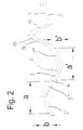
- Fig. 2
- 2 shows a detailed view according to FIG. 1,
- Fig. 3
- 2 and a corresponding detailed view of a stent designed according to the invention in the expanded state,
- Fig. 4
- 5 shows a further detailed view of a stent designed according to the invention in the radial and tangential direction,
- Fig. 5
- a schematic cross section through an inventive stent and
- 6 to 9
- Partial views of the lattice structure of further embodiments of a stent designed according to the invention.
Fig. 1 zeigt ein Schnittmuster, wie es beispielsweise mittels eines Lasers in die Wand eines röhrenförmigen Körpers 1 (siehe Fig. 5) zur Herstellung eines erfindungsgemäß ausgebildeten Stents geschnitten wird. Zur Verdeutlichung der Lage der Schnitte innerhalb der Wand des röhrenförmigen Körpers 1 ist in Fig. 1 der Verlauf der Längsachse des röhrenförmigen Körpers 1 mit dem Bezugszeichen 2 versehen.1 shows a cutting pattern as it is cut, for example, by means of a laser into the wall of a tubular body 1 (see FIG. 5) in order to produce a stent designed according to the invention. To clarify the position of the cuts within the wall of the
Durch den Schneidvorgang entstehen in der Wand des röhrenförmigen Körpers 1 Durchbrechungen 3, 4, die im komprimierten Zustand die Form der in Fig. 1 dargestellten schlitzförmigen Öffnungen besitzen.The cutting process creates
Die schlitzförmigen Öffnungen 3 weisen drei Abschnitte 3', 3'' und 3''' auf, die jeweils schräg zur Längsachse 2 des röhrenförmigen Körpers 1 angeordnet sind und zusammen jeweils Z-förmige schlitzförmige Öffnungen 3 bilden.The slit-shaped
Das zwischen den Durchbrechungen 3 liegende Material der Wand des röhrenförmigen Körpers 1 bildet jeweils Umrandungselemente 5, die, wie besonders gut in Fig. 3b zu erkennen ist, jeweils Umgrenzungen für die Durchbrechungen 3 darstellen.The material of the wall of the
Die Durchbrechungen 3 sind punktsymmetrisch zu Symmetriepunkten 6 ausgebildet, die zusammen mit den jeweiligen Enden 7, 8 der Durchbrechungen 3 auf Parallelen zu der Längsachse 2 des röhrenförmigen Körpers 1 liegen. Der Symmetriepunkt 6 ist dabei in der Mitte zwischen den beiden Enden 7, 8 der Durchbrechungen 3 angeordnet.The
Jeweils zwei in Umfangsrichtung des röhrenförmigen Körpers 1 benachbart angeordnete (in Fig. 1 übereinanderliegende) Umrandungselemente 5 sind über Verbindungsstellen 10 miteinander verbunden, welche jeweils zwischen den Symmetriepunkten 6 der Umrandungselemente 5 angeordnet sind.In each case two
Die einander zugewandten Enden 11, 12 von jeweils zwei in Längsrichtung benachbart angeordneten Umrandungselementen 5 sind jeweils über V-förmige Zwischenelemente 13 miteinander verbunden. Die Schenkel 14, 15 der Zwischenelemente 13 sind jeweils schräg zur Längsachse 2 des röhrenförmigen Körpers 1 angeordnet.The mutually facing ends 11, 12 of two
Die durch das in Fig. 1 dargestellte Schnittmuster erzeugten Durchbrechungen 3, 4 sind gleichmäßig über den gesamten Umfang des röhrenförmigen Körpers 1 verteilt, so daß beispielsweise die in Fig. 1 dargestellten Umrandungselemente 5' und 5'' zusammenfallen.The
Je nach Länge des röhrenförmigen Körpers 1 können mehr oder weniger V-förmige Zwischenelemente 13 und Umrandungselemente 5 entlang der Längsachse 2 des röhrenförmigen Körpers 1 verteilt sein als in Fig. 1 dargestellt sind. Entsprechend kann je nach Umfang des röhrenförmigen Körpers 1 die Anzahl der V-förmigen Zwischenelemente 13 und der Umrandungselemente 5 entlang des Umfangs des röhrenförmigen Körpers 1 variieren.Depending on the length of the
Aus Fig. 2 ist besonders deutlich der punktsymmetrische Aufbau der schlitzförmigen Öffnungen 3 und damit der Umrandungselemente 5 zu erkennen. Insbesondere werden die Vorteile eines erfindungsgemäßen Stents dadurch erreicht, daß die in Längsrichtung mit a und a' bzw. in Umfangsrichtung des röhrenförmigen Körpers 1 mit b und b' bezeichneten geometrischen Abstände jeweils gleich groß sind.The point-symmetrical structure is particularly clear from FIG the slot-shaped
In Fig. 3 ist zu erkennen, wie durch Aufweiten der Durchbrechung 3 die Breite des Umrandungselementes 5 in Umfangsrichtung des röhrenförmigen Körpers 1 zunimmt, wodurch eine Expansion des röhrenförmigen Körpers 1 erreicht wird. Weiterhin ist Fig. 3 zu entnehmen, daß die auftretende Längsverkürzung des Umrandungselementes 5, die daran erkannt wird, daß das Ende 11 der Umrandung 5 in Fig. 3b gegenüber der Position in Fig. 3a nach links verschoben ist, durch ein gleichzeitiges Aufweiten des V-förmigen Zwischenelements 13 ausgeglichen wird, so daß die Positionen des Endes 12 des benachbart angeordneten Umrandungselements 5 im komprimierten (Fig. 3a) und im expandierten (Fig. 3b) Zustand übereinstimmen. Auf diese Weise besitzt jeweils eine Einheit aus Umrandungselement 5 und Zwischenelement 13 - und somit auch der röhrenförmige Körper 1 insgesamt - im komprimierten Zustand dieselbe Länge wie im expandierten Zustand.In Fig. 3 it can be seen how the width of the
Im Bereich der Verbindungsstellen 10 zwischen zwei in Umfangsrichtung des röhrenförmigen Körpers 1 benachbart angeordneten Rahmenelementen 5 sind Ausnehmungen 16 vorgesehen, so daß an diesen Stellen das Abbiegen der Umrandungselemente 5 erleichtert wird. Dadurch werden die elastische Eigenschaften eines erfindungsgemäßen Stents weiter verbessert.In the area of the connection points 10 between two
In Fig. 4 sind die Ausnehmungen 16 im Detail dargestellt, wie sie beispielsweise zwischen zwei unmittelbar miteinander verbundenen Umrandungselementen 5 vorgesehen sein können. Entsprechende Ausnehmungen 16 können auch zwischen den Umrandungselementen 5 und den V-förmigen Zwischenelementen 13 vorgesehen sein. Dabei sind sowohl Ausnehmungen in Umfangsrichtung, wie sie in Fig. 4a dargestellt sind, als auch Ausnehmungen in radialer Richtung, wie sie in Fig. 4b dargestellt sind, sowie jede weitere Art von Ausnehmungen möglich, die die Flexiblität des erfindungsgemäß ausgebildeten Stents günstig beeinflussen.4 shows the
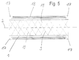
In dem in Fig. 5 schematisch dargestellten Querschnitt eines erfindungsgemäß ausgebildeten Stents 1 sind die Durchbrechungen 3 lediglich durch schräg verlaufende Striche 19 angedeutet. Der röhrenförmige Körper 1 weist an seinen beiden Enden jeweils in Umfangsrichtung verlaufende, als Vorsprünge 17 ausgebildete Verdickungen auf, welche sich radial nach außen erstrecken. Zwischen den Vorsprüngen 17 ist eine elastische Ummantelung 18 vorgesehen, deren radiale Stärke im wesentlichen gleich der radialen Abmessungen der überstehenden Teile der Vorsprünge 17 ist, so daß der Stent eine im wesentlichen gleichmäßige Außenfläche aufweist. Weiterhin ist aus Fig. 5 erkennbar, daß die Innenfläche des röhrenförmigen Körpers 1 gleichmäßig verlaufend ausgebildet ist.In the cross section, shown schematically in FIG. 5, of a
Der erfindungsgemäß ausgebildete Stent wird bevorzugt wie folgt hergestellt, vorbereitet und verwendet:The stent designed according to the invention is preferably produced, prepared and used as follows:
In die Wand eines aus Memory-Metall bestehenden röhrenförmigen Körpers 1 werden mit einem Laser das in Fig. 1 dargestellte Schnittmuster und damit die schlitzförmigen Öffnungen 3, 4 geschnitten. Der Durchmesser des röhrenförmigen Körpers 1 wird dabei so gewählt, daß er dem zum Implantieren benötigten komprimierten Zustand des Stents entspricht.In the wall of a
Nachdem das in Fig. 1 dargestellte Schnittmuster über die gesamte Länge und den gesamten Umfang des röhrenförmigen Körpers 1 eingeschnitten wurde, wird der röhrenförmige Körper 1 auf eine Expansionsachse aufgezogen, deren Durchmesser, dem im eingesetzten, expandierten Zustand benötigten Durchmesser des Stents entspricht. Dadurch werden die schlitzförmigen Öffnungen 3 und 4 ausgeweitet, wie es in Fig. 3b dargestellt ist. Anschließend wird der auf die Expansionsachse aufgezogene röhrenförmige Körper in Längsrichtung soweit gedehnt, bis die durch die Expansion auftretende Verkürzung durch Aufbiegen der V-förmigen Zwischenelemente 13 kompensiert ist, so daß eine Oberflächenstruktur aus Umrandungselementen 5 und Zwischenelementen 13 entsteht, wie sie in Fig. 3b dargestellt sind.After the cutting pattern shown in FIG. 1 has been incised over the entire length and the entire circumference of the
Durch Erhitzen des röhrenförmigen Körpers über die Memory-Temperatur wird die entstandende Form anschließend in dem Material gespeichert.By heating the tubular body above the memory temperature, the resulting shape is then stored in the material.
Nach Abkühlen des Stents unter die Konversionstemperatur kann der Stent wieder auf seinen dem komprimierten Zustand entsprechenden Ausgangsdurchmesser zusammengedrückt werden und mit einer elastischen Ummantelung 18, die beispielsweise aus Nylon, Polyethylen, Polyamid oder Polyurethanelastomeren besteht, überzogen werden. Durch die Vorsprünge 17 wird ein versehentliches Abstreifen der elastischen Ummantelung 18 beim Implantieren verhindert. Gleichzeitig kann durch die Vorsprünge 17 der Stent beim Einsetzen über den Röntgenschirm besser beobachtet werden, so daß eine einwandfreie Positionierung des Stents an der gewünschten Stelle innerhalb des Hohlorgans gewährleistet ist.After the stent has cooled below the conversion temperature, the stent can be compressed again to its initial diameter corresponding to the compressed state and covered with an
Der Stent wird über einen Einführkatheter an der gewünschten Stelle positioniert, wobei ein Expandieren des Stents beispielsweise durch eine zusätzliche Umhüllung oder einen speziellen Katheter verhindert wird. Durch Abstreifen der Umhüllung oder des Katheters nimmt der röhrenförmige Körper 1 aufgrund der über der Konversionstemperatur liegenden Körpertemperatur seine gespeicherte Form an. Dabei stimmt aufgrund der durch die Zwischenelemente 13 erreichten Verkürzungskompensation die Länge im expandierten Zustand mit der Länge des Stents im komprimierten Zustand überein, so daß die beim Einsetzen über den Röntgenschirm beobachtete Position beider Enden des Stents eingehalten wird.The stent is positioned at the desired location via an insertion catheter, whereby expansion of the stent is prevented, for example by an additional sheath or a special catheter. By stripping off the sheath or the catheter, the
Aufgrund der erfindungsgemäßen Struktur des röhrenförmigen Körpers 1 wird sowohl im komprimierten als auch im expandierten Zustand eine hohe Flexibilität erreicht, so daß sowohl eine Implantation in kurvenförmige Hohlorgane als auch in im Bereich von Gelenken angeordnete Hohlorgane möglich ist. Ein Abknicken des Stents durch Abbiegen der Gelenke wird durch die erzielte hohe Flexibilität weitgehend ausgeschlossen. Darüber hinaus ist durch die erfindungsgemäß ausgebildete Struktur sowohl im komprimierten als auch im expandierten Zustand eine gute Längs- und Querstabilität des Stents gewährleistet.Due to the structure of the
Weiterhin sind sowohl die Außenseite als auch die Innenseite des röhrenförmigen Körpers gleichmäßig ausgebildet und weisen insbesondere keine scharfkantigen nach außen oder innen hervorstehenden Elemente auf, so daß weder Verletzungen des Hohlorgans noch eines eventuell die Expansion unterstützenden Ballons eines Ballonkatheters auftreten können.Furthermore, both the outside and the inside of the tubular body are formed uniformly and in particular have no sharp-edged elements protruding outwards or inwards, so that neither injuries to the hollow organ nor a balloon of a balloon catheter, which may support expansion, can occur.
Außer durch die beschriebene Ausführungsform aus Memory-Metall können die Vorteile eines erfindungsgemäß ausgebildeten Stents auch bei Verwendung anderer Materialien, wie beispielsweise Tantal, Edelstahl oder körperverträglicher Kunststoffe, beispielsweise Polyethylen, Polyamid oder Polyurethanelastomere erreicht werden.In addition to the memory metal embodiment described, the advantages of a stent designed according to the invention can also be achieved when using other materials, such as, for example, tantalum, stainless steel or body-compatible plastics, for example polyethylene, polyamide or polyurethane elastomers.
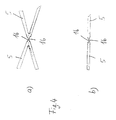
Die in Figur 6 dargestellte Gitterstruktur 26 eines erfindungsgemäß ausgebildeten Stents besteht aus sich in Richtung der Längsachse des Stents erstreckenden sinuswellenförmigen Längskomponenten 20, welche die Umrandungselemente 5 bilden und die Öffnungen 3 zwischen sich einschließen. Jeweils in Umfangsrichtung nebeneinander angeordnete Längskomponenten 20 sind an einzelnen, einander zugewandten Scheitelpunkten 21, 21' über Verbindungsstellen 10 miteinander verbunden, während zwischen übrigen, einander zugewandten Scheitelpunkten 22, 23 keine Verbindung besteht.The
Die Verbindungsstellen 10 zwischen verschiedenen Scheitelpunkten 21, 21' sind in Längsrichtung des Stents zueinander versetzt angeordnet. Durch die versetzte Anordnung der Verbindungsstellen 10 sowie durch die unverbundenen, gegeneinander verschiebbaren Scheitelpunkte 22, 23 wird sowohl in Längsrichtung als auch quer zur Längsachse des Stents eine gute Flexibilität ohne die Erzeugung von scharfkantigen Elementen erreicht. Der Stent kann dabei aus einem selbstexpandierenden Material, wie beispielsweise Nitinol, aus Edelstahl, aus Tantal oder aus einem sonstigen geeigneten Material hergestellt sein.The connection points 10 between
Weiterhin kann der Stent mit oder ohne Balloninsufflation auf den gewünschten Durchmesser ausgedehnt werden.Furthermore, the stent can be expanded to the desired diameter with or without balloon insufflation.
Der Stent weist eine gute Längsstabilität auf, wobei gleichzeitig die Tendenz zum Abknicken in engen Kurven weiter verringert ist. Weiterhin ist es möglich für weitergehende Anwendungen die Gitterstruktur mit Kunststoffen, Medikamenten oder textilen Geflechten zu beschichten, beispielsweise als endovaskuläre Prothese zur Behandlung krankhafter Aufweitungen oder Defekte.The stent has good longitudinal stability, while at the same time the tendency to kink in tight curves is further reduced. It is also possible for further applications to coat the lattice structure with plastics, medication or textile braids, for example as an endovascular prosthesis for the treatment of pathological widenings or defects.
In der in Figur 7 gezeigten Teilansicht der Gitterstruktur 26 einer weiteren Ausführungsform eines erfindungsgemäß ausgebildeten Stents sind die Verbindungsstellen 10 zwischen den Scheitelpunkten 21, 21' als Verbindungsstege ausgebildet.In the partial view of the
Bei der Ausführungsform nach Figur 8 sind die sinuswellenförmigen Längskomponenten 20 in Längsrichtung versetzt zueinander angeordnet, wobei die Verbindungen zwischen den in Umfangsrichtung benachbart angeordneten Längskomponenten 20 über ausgeprägte Verbindungsbrücken 24 erfolgt. Die Verbindungsbrücken 24 sind dabei an beliebigen Stellen zwischen den Längskomponenten 20 angeordnet.In the embodiment according to FIG. 8, the sinusoidal wave-shaped
Bei dem Ausführungsbeispiel nach Figur 9 sind die Längskomponenten 20 schräg zur Längsachse 2 des Stents verlaufend angeordnet. Auf diese Weise entsteht eine spiralige Anordnung der Längskomponenten 20 um die Längsachse 2 des Stents herum. Durch diese spiralige Anordnung werden zum einen die elastischen Aufstellkräfte der Längskomponenten 20 erhöht, so daß die Stabilität des Stents im expandierten Zustand weiter verbessert werden kann. Zum anderen kann eine auf der Außenseite des Stents angeordnete Hülle, mit der der Stent beim Einsetzen im komprimierten Zustand gehalten wird, aufgrund der spiraligen Anordnung der Längskomponenten 20 durch Drehung leicht wieder auf den bereits teilweise expandierten Stent aufgezogen werden, so daß bei unbefriedigender Positionierung der Stent repositioniert werden kann.In the embodiment of Figure 9, the
Claims (14)
dadurch gekennzeichnet,
daß jede Durchbrechung (3, 4) zumindest einen Abschnitt (3', 3'', 3''') aufweist, der sowohl im komprimierten als auch im expandierten Zustand des Stents schräg zu dessen Längsachse (2) angeordnet ist.Stent for transluminal implantation in hollow organs, especially in blood vessels, ureters, esophagus or biliary tract, with an essentially tubular body (1), which can be converted from a compressed state with a first cross-sectional diameter to an expanded state with an enlarged second cross-sectional diameter, the Wall of the tubular body (1) has repetitive openings (3, 4) which repeat both in the longitudinal direction and in the circumferential direction of the stent,
characterized by
that each opening (3, 4) has at least one section (3 ', 3'',3''') which is arranged obliquely to its longitudinal axis (2) both in the compressed and in the expanded state of the stent.
dadurch gekennzeichnet,
daß die Durchbrechungen (3, 4) im komprimierten Zustand des Stents in der Wand des röhrenförmigen Körpers (1) schlitzförmige Öffnungen bilden, wobei die schlitzförmigen Öffnungen (3) vorzugsweise mehrere, insbesondere drei Abschnitte (3', 3'', 3''') aufweisen, die schräg zur Längsachse (2) des Stents angeordnet sind.The stent of claim 1,
characterized by
that the openings (3, 4) form slit-shaped openings in the compressed state of the stent in the wall of the tubular body (1), the slit-shaped openings (3) preferably having several, in particular three sections (3 ', 3'',3''') which are arranged obliquely to the longitudinal axis (2) of the stent.
dadurch gekennzeichnet,
daß die schlitzförmigen Öffnungen (3) im wesentlichen zick-zack-förmig, Z-förmig, S-förmig oder wellenförmig, insbesondere sinusförmig ausgebildet sind.Stent according to claim 2,
characterized by
that the slit-shaped openings (3) are essentially zigzag, Z-shaped, S-shaped or wave-shaped, in particular sinusoidal.
dadurch gekennzeichnet,
daß die Neigung der Abschnitte (3', 3'', 3''') zur Längsachse (2) des Stents im komprimierten Zustand jeweils zwischen 1° und 75°, insbesondere zwischen 10° und 45° beträgt.Stent according to one of the preceding claims,
characterized by
that the inclination of the sections (3 ', 3'',3''') to the longitudinal axis (2) of the stent in the compressed state is in each case between 1 ° and 75 °, in particular between 10 ° and 45 °.
dadurch gekennzeichnet,
daß die Durchbrechungen (3) im wesentlichen punktsymmetrisch ausgebildet sind und/oder die beiden Enden (7, 8) der Durchbrechungen (3) auf einer Parallelen zur Längsachse (2) des Stents angeordnet sind, wobei insbesondere der Symmetriepunkt (6) auf der Parallelen zur Längsachse (2) des Stents in der Mitte zwischen den beiden Enden (7, 8) der Durchbrechungen (3) angeordnet ist.Stent according to one of the preceding claims,
characterized by
that the openings (3) are essentially point-symmetrical and / or the two ends (7, 8) of the openings (3) are arranged on a parallel to the longitudinal axis (2) of the stent, in particular the point of symmetry (6) on the parallel to the longitudinal axis (2) of the stent in the middle between the two ends (7, 8) of the openings (3).
dadurch gekennzeichnet,
daß das zwischen den Durchbrechungen (3) liegende Material der Wand des röhrenförmigen Körpers (1) Umrandungselemente (5) für die Durchbrechungen (3) bildet, die zur Expansion des Stents aufweitbar sind, wobei vorzugsweise zwei in Umfangsrichtung benachbart angeordnete Umrandungselemente (5) insbesondere über einen Steg (10) miteinander verbunden sind und bevorzugt die Verbindungsstelle (10) jeweils im Bereich der Mitte zwischen den beiden Enden (11, 12) der Umrandungselemente (5) angeordnet ist.Stent according to one of the preceding claims,
characterized by
that the material lying between the openings (3) of the wall of the tubular body (1) forms border elements (5) for the openings (3) which can be expanded to expand the stent, preferably two border elements (5) arranged adjacent in the circumferential direction in particular are connected to one another via a web (10) and the connection point (10) is preferably arranged in the region in the middle between the two ends (11, 12) of the border elements (5).
dadurch gekennzeichnet,
daß die einander zugewandten Enden (11, 12) von in Längsrichtung benachbart angeordneten Umrandungselementen (5) insbesondere über elastische, bevorzugt V-förmig ausgebildete Zwischenelemente (13) miteinander verbunden sind und die Zwischenelemente (13) insbesondere Abschnitte (14, 15) aufweisen, die schräg zur Längsachse (2) des Stents angeordnet sind.Stent according to one of the preceding claims,
characterized by
that the mutually facing ends (11, 12) of bordering elements (5) arranged adjacent to one another in the longitudinal direction are connected to one another, in particular via elastic, preferably V-shaped intermediate elements (13) and the intermediate elements (13) in particular have sections (14, 15), which are arranged obliquely to the longitudinal axis (2) of the stent.
dadurch gekennzeichnet,
daß die Verbindungsstellen (10) zwischen den Umrandungselementen und/oder die Verbindungsstellen zwischen den Umrandungselementen und den Zwischenelementen in radialer und/oder axialer Richtung verjüngt ausgebildet sind.Stent according to one of claims 6 or 7,
characterized by
that the connection points (10) between the border elements and / or the connection points between the border elements and the intermediate elements are tapered in the radial and / or axial direction.
dadurch gekennzeichnet,
daß der röhrenförmige Körper (1) aus Memory-Metall, insbesondere aus Nitinol, und/oder aus körperverträglichem Kunststoff, insbesondere aus Polyethylen (PE), Polyamid (PA) oder Polyurethanelastomeren (PUR) hergestellt ist.Stent according to one of the preceding claims,
characterized by
that the tubular body (1) is made of memory metal, in particular of nitinol, and / or of body-compatible plastic, in particular of polyethylene (PE), polyamide (PA) or polyurethane elastomers (PUR).
dadurch gekennzeichnet,
daß zumindest ein Ende des röhrenförmigen Körpers (1) eine insbesondere in Umfangsrichtung verlaufende Verdickung (17) aufweist, die insbesondere nach außen, vorzugsweise in radialer Richtung nach außen übersteht.Stent according to one of the preceding claims,
characterized by
that at least one end of the tubular body (1) has a thickening (17), in particular extending in the circumferential direction, which projects in particular outwards, preferably in the radial direction outwards.
dadurch gekennzeichnet,
daß an der Außenseite des röhrenförmigen Körpers (1) eine elastische Ummantelung (18) vorgesehen ist und/oder an jedem Ende des röhrenförmigen Körpers (1) eine nach außen überstehende Verdickung (17) vorgesehen ist und die elastische Ummantelung (18) zwischen den überstehenden Verdickungen (17) angeordnet ist, wobei bevorzugt die Materialstärke der elastischen Ummantelung (18) und die radialen Abmessungen der überstehenden Teile der Verdickungen (17) im wesentlichen gleich groß sind.Stent according to one of the preceding claims,
characterized by
that on the outside of the tubular body (1) an elastic jacket (18) is provided and / or at each end of the tubular body (1) an outwardly projecting thickening (17) is provided and the elastic jacket (18) between the projecting Thickenings (17) are arranged, the material thickness of the elastic sheathing (18) and the radial dimensions of the protruding parts of the thickenings (17) preferably being substantially the same size.
dadurch gekennzeichnet,
daß die elastische Ummantelung (18) aus Kunststoff, insbesondere aus Polyethylen (PE), Polyamid (PA) oder Polyurethanelastomeren (PUR) besteht und/oder der Querschnittsdurchmesser des röhrenförmigen Körpers (1) zwischen 1 mm und 5 cm, insbesondere zwischen 3 mm und 3 cm liegt.Stent according to one of the preceding claims,
characterized by
that the elastic sheath (18) made of plastic, in particular polyethylene (PE), polyamide (PA) or polyurethane elastomers (PUR) and / or the cross-sectional diameter of the tubular body (1) between 1 mm and 5 cm, in particular between 3 mm and 3 cm.
gekennzeichnet durch
eine wabenartige, einstückig ausgebildete Gitterstruktur (26), ohne scharfkantige Lücken, mit sinuswellenförmigen Längskomponenten (20), die an den Berührungspunkten (21, 21', 22, 23) nicht durchgehend, sondern zur Ermöglichung von Längs- und Querverbiegungen insbesondere über Brückenelemente (24) unterschiedlich versetzt seitlich verbunden sind, wobei die sinuswellenartigen Längskomponenten (20) insbesondere spiralig zur Längsachse (25) des Stents angeordnet sind und/oder vorzugsweise unterschiedliche Amplituden aufweisen.The stent of claim 13,
characterized by
a honeycomb-like, one-piece lattice structure (26), without sharp-edged gaps, with sinusoidal longitudinal components (20) that are not continuous at the points of contact (21, 21 ', 22, 23), but to enable longitudinal and transverse bending, in particular via bridge elements ( 24) are laterally connected with different displacements, the sine wave-like longitudinal components (20) being arranged in particular spirally to the longitudinal axis (25) of the stent and / or preferably having different amplitudes.
Applications Claiming Priority (6)
| Application Number | Priority Date | Filing Date | Title |
|---|---|---|---|
| DE19512066 | 1995-04-01 | ||
| DE1995112066 DE19512066A1 (en) | 1995-04-01 | 1995-04-01 | Stent for transluminal implantation e.g. blood vessels |
| DE19516191 | 1995-05-07 | ||
| DE1995116191 DE19516191A1 (en) | 1995-04-01 | 1995-05-07 | Support (stent, prosthesis) for canalicular body structures, e.g. Blood vessels, bile ducts, esophagus and trachea |
| DE1995140851 DE19540851A1 (en) | 1995-10-30 | 1995-10-30 | Stent for transluminal implantation e.g. blood vessels |
| DE19540851 | 1995-10-30 |
Publications (5)
| Publication Number | Publication Date |
|---|---|
| EP0734698A2 true EP0734698A2 (en) | 1996-10-02 |
| EP0734698A3 EP0734698A3 (en) | 1997-06-18 |
| EP0734698B1 EP0734698B1 (en) | 1998-08-12 |
| EP0734698B2 EP0734698B2 (en) | 2006-03-29 |
| EP0734698B9 EP0734698B9 (en) | 2006-07-05 |
Family
ID=27215007
Family Applications (1)
| Application Number | Title | Priority Date | Filing Date |
|---|---|---|---|
| EP96104982A Expired - Lifetime EP0734698B9 (en) | 1995-04-01 | 1996-03-28 | Stent for transluminal implantation into hollow organs |
Country Status (6)
| Country | Link |
|---|---|
| US (1) | US5876449A (en) |
| EP (1) | EP0734698B9 (en) |
| JP (1) | JP3168531B2 (en) |
| AT (1) | ATE169484T1 (en) |
| DK (1) | DK0734698T4 (en) |
| ES (1) | ES2119527T5 (en) |
Cited By (43)
| Publication number | Priority date | Publication date | Assignee | Title |
|---|---|---|---|---|
| WO1997026840A1 (en) * | 1996-01-26 | 1997-07-31 | Deka Products Limited Partnership | Axially flexible stent |
| WO1998018407A1 (en) * | 1996-10-28 | 1998-05-07 | BIOTRONIK MESS- UND THERAPIEGERäTE GMBH & CO. INGENIEURBüRO BERLIN | Stent |
| JPH10155915A (en) * | 1996-11-29 | 1998-06-16 | Piolax Inc | Stent |
| WO1998044871A1 (en) * | 1997-04-07 | 1998-10-15 | Deka Products Limited Partnership | Axially flexible stent |
| WO1998032412A3 (en) * | 1997-01-24 | 1998-11-12 | Scimed Life Systems Inc | Bistable spring construction for a stent and other medical apparatus |
| WO1999012495A1 (en) | 1997-09-09 | 1999-03-18 | Micro Science Medical Ag | Stent for transluminal implantation |
| WO1999039660A1 (en) * | 1998-02-03 | 1999-08-12 | B. Braun Celsa | Prosthesis with undulating longitudinal braces |
| US5938682A (en) * | 1996-01-26 | 1999-08-17 | Cordis Corporation | Axially flexible stent |
| WO2000015145A1 (en) * | 1998-09-10 | 2000-03-23 | Scimed Life Systems, Inc. | Improved stent configurations |
| FR2784574A1 (en) * | 1998-10-15 | 2000-04-21 | Braun Celsa Sa | One-piece tubular endoprosthesis for anatomical duct |
| EP1034751A3 (en) * | 1999-03-05 | 2000-10-04 | Terumo Kabushiki Kaisha | Implanting stent and dilating device |
| US6190403B1 (en) | 1998-11-13 | 2001-02-20 | Cordis Corporation | Low profile radiopaque stent with increased longitudinal flexibility and radial rigidity |
| US6241762B1 (en) | 1998-03-30 | 2001-06-05 | Conor Medsystems, Inc. | Expandable medical device with ductile hinges |
| US6258116B1 (en) | 1996-01-26 | 2001-07-10 | Cordis Corporation | Bifurcated axially flexible stent |
| US6261319B1 (en) * | 1998-07-08 | 2001-07-17 | Scimed Life Systems, Inc. | Stent |
| US6293967B1 (en) | 1998-10-29 | 2001-09-25 | Conor Medsystems, Inc. | Expandable medical device with ductile hinges |
| US6669722B2 (en) | 2000-09-22 | 2003-12-30 | Cordis Corporation | Stent with optimal strength and radiopacity characteristics |
| US6740114B2 (en) | 2001-03-01 | 2004-05-25 | Cordis Corporation | Flexible stent |
| US6746476B1 (en) | 1997-09-22 | 2004-06-08 | Cordis Corporation | Bifurcated axially flexible stent |
| US6770088B1 (en) | 1996-04-26 | 2004-08-03 | Scimed Life Systems, Inc. | Intravascular stent |
| US6790227B2 (en) | 2001-03-01 | 2004-09-14 | Cordis Corporation | Flexible stent |
| EP1649830A1 (en) * | 1995-10-16 | 2006-04-26 | Oren Globerman | Medical stents |
| EP1719479A2 (en) * | 2002-03-28 | 2006-11-08 | Boston Scientific Limited | Improved stent |
| US7479127B2 (en) | 1999-05-20 | 2009-01-20 | Innovational Holding, Llc | Expandable medical device delivery system and method |
| US7766956B2 (en) | 2000-09-22 | 2010-08-03 | Boston Scientific Scimed, Inc. | Intravascular stent and assembly |
| US7862609B2 (en) | 2000-11-16 | 2011-01-04 | Cordis Corporation | Stent graft having a pleated graft member |
| US7942922B2 (en) | 1997-06-13 | 2011-05-17 | Orbusneich Medical, Inc. | Stent having helical elements |
| US8029561B1 (en) | 2000-05-12 | 2011-10-04 | Cordis Corporation | Drug combination useful for prevention of restenosis |
| US8182527B2 (en) | 2001-05-07 | 2012-05-22 | Cordis Corporation | Heparin barrier coating for controlled drug release |
| US8197881B2 (en) | 2003-09-22 | 2012-06-12 | Conor Medsystems, Inc. | Method and apparatus for loading a beneficial agent into an expandable medical device |
| US8211162B2 (en) | 2007-05-25 | 2012-07-03 | Boston Scientific Scimed, Inc. | Connector node for durable stent |
| US8221490B2 (en) | 1998-10-23 | 2012-07-17 | Boston Scientific Scimed, Inc. | Helical stent design |
| US8236048B2 (en) | 2000-05-12 | 2012-08-07 | Cordis Corporation | Drug/drug delivery systems for the prevention and treatment of vascular disease |
| US8337650B2 (en) | 1995-03-10 | 2012-12-25 | Bard Peripheral Vascular, Inc. | Methods for making a supported graft |
| US8353948B2 (en) | 1997-01-24 | 2013-01-15 | Celonova Stent, Inc. | Fracture-resistant helical stent incorporating bistable cells and methods of use |
| US8435280B2 (en) | 2005-03-31 | 2013-05-07 | Boston Scientific Scimed, Inc. | Flexible stent with variable width elements |
| US8562665B2 (en) | 1998-02-02 | 2013-10-22 | Boston Scientific Scimed, Inc. | Tubular stent consists of chevron-shape expansion struts and contralaterally attached diagonal-connectors |
| US8617337B2 (en) | 1999-02-02 | 2013-12-31 | Bard Peripheral Vascular, Inc. | Partial encapsulation of stents |
| US8617441B2 (en) | 1995-03-10 | 2013-12-31 | Bard Peripheral Vascular, Inc. | Methods for making an encapsulated stent |
| US8663311B2 (en) | 1997-01-24 | 2014-03-04 | Celonova Stent, Inc. | Device comprising biodegradable bistable or multistable cells and methods of use |
| US9445926B2 (en) | 1996-04-26 | 2016-09-20 | Boston Scientific Scimed, Inc. | Intravascular stent |
| US9498357B2 (en) | 2012-11-05 | 2016-11-22 | Variomed Ag | Stent |
| CN108852575A (en) * | 2018-07-11 | 2018-11-23 | 浙江巴泰医疗科技有限公司 | A kind of more piece application operating system of closed self-expanding unit rack |
Families Citing this family (131)
| Publication number | Priority date | Publication date | Assignee | Title |
|---|---|---|---|---|
| US20070073384A1 (en) * | 1995-03-01 | 2007-03-29 | Boston Scientific Scimed, Inc. | Longitudinally flexible expandable stent |
| US7204848B1 (en) | 1995-03-01 | 2007-04-17 | Boston Scientific Scimed, Inc. | Longitudinally flexible expandable stent |
| US6783543B2 (en) * | 2000-06-05 | 2004-08-31 | Scimed Life Systems, Inc. | Intravascular stent with increasing coating retaining capacity |
| US6241760B1 (en) * | 1996-04-26 | 2001-06-05 | G. David Jang | Intravascular stent |
| US5954743A (en) * | 1996-04-26 | 1999-09-21 | Jang; G. David | Intravascular stent |
| US5868782A (en) | 1996-12-24 | 1999-02-09 | Global Therapeutics, Inc. | Radially expandable axially non-contracting surgical stent |
| DE29702671U1 (en) | 1997-02-17 | 1997-04-10 | Jomed Implantate Gmbh | Stent |
| US6977095B1 (en) * | 1997-10-01 | 2005-12-20 | Wright Medical Technology Inc. | Process for producing rigid reticulated articles |
| US6013091A (en) * | 1997-10-09 | 2000-01-11 | Scimed Life Systems, Inc. | Stent configurations |
| US6190406B1 (en) * | 1998-01-09 | 2001-02-20 | Nitinal Development Corporation | Intravascular stent having tapered struts |
| WO1999044535A1 (en) * | 1998-03-05 | 1999-09-10 | Boston Scientific Limited | Intraluminal stent |
| US6179868B1 (en) * | 1998-03-27 | 2001-01-30 | Janet Burpee | Stent with reduced shortening |
| US6887268B2 (en) * | 1998-03-30 | 2005-05-03 | Cordis Corporation | Extension prosthesis for an arterial repair |
| US7208010B2 (en) | 2000-10-16 | 2007-04-24 | Conor Medsystems, Inc. | Expandable medical device for delivery of beneficial agent |
| US20040254635A1 (en) | 1998-03-30 | 2004-12-16 | Shanley John F. | Expandable medical device for delivery of beneficial agent |
| US6461380B1 (en) * | 1998-07-28 | 2002-10-08 | Advanced Cardiovascular Systems, Inc. | Stent configuration |
| US6682554B2 (en) * | 1998-09-05 | 2004-01-27 | Jomed Gmbh | Methods and apparatus for a stent having an expandable web structure |
| US6755856B2 (en) | 1998-09-05 | 2004-06-29 | Abbott Laboratories Vascular Enterprises Limited | Methods and apparatus for stenting comprising enhanced embolic protection, coupled with improved protection against restenosis and thrombus formation |
| US7887578B2 (en) | 1998-09-05 | 2011-02-15 | Abbott Laboratories Vascular Enterprises Limited | Stent having an expandable web structure |
| US20020019660A1 (en) * | 1998-09-05 | 2002-02-14 | Marc Gianotti | Methods and apparatus for a curved stent |
| DE19840645A1 (en) * | 1998-09-05 | 2000-03-09 | Jomed Implantate Gmbh | Stent |
| US7815763B2 (en) | 2001-09-28 | 2010-10-19 | Abbott Laboratories Vascular Enterprises Limited | Porous membranes for medical implants and methods of manufacture |
| US10307147B2 (en) | 1999-08-09 | 2019-06-04 | Edwards Lifesciences Corporation | System for improving cardiac function by sealing a partitioning membrane within a ventricle |
| US20060229491A1 (en) * | 2002-08-01 | 2006-10-12 | Cardiokinetix, Inc. | Method for treating myocardial rupture |
| US8257428B2 (en) * | 1999-08-09 | 2012-09-04 | Cardiokinetix, Inc. | System for improving cardiac function |
| US7674222B2 (en) * | 1999-08-09 | 2010-03-09 | Cardiokinetix, Inc. | Cardiac device and methods of use thereof |
| US7582051B2 (en) * | 2005-06-10 | 2009-09-01 | Cardiokinetix, Inc. | Peripheral seal for a ventricular partitioning device |
| US8529430B2 (en) * | 2002-08-01 | 2013-09-10 | Cardiokinetix, Inc. | Therapeutic methods and devices following myocardial infarction |
| US8388672B2 (en) | 1999-08-09 | 2013-03-05 | Cardiokinetix, Inc. | System for improving cardiac function by sealing a partitioning membrane within a ventricle |
| US7303526B2 (en) * | 1999-08-09 | 2007-12-04 | Cardiokinetix, Inc. | Device for improving cardiac function |
| US9694121B2 (en) | 1999-08-09 | 2017-07-04 | Cardiokinetix, Inc. | Systems and methods for improving cardiac function |
| US20030109770A1 (en) * | 1999-08-09 | 2003-06-12 | Sharkey Hugh R. | Device with a porous membrane for improving cardiac function |
| US8500795B2 (en) | 1999-08-09 | 2013-08-06 | Cardiokinetix, Inc. | Retrievable devices for improving cardiac function |
| US6468301B1 (en) | 2000-03-27 | 2002-10-22 | Aga Medical Corporation | Repositionable and recapturable vascular stent/graft |
| US6616689B1 (en) | 2000-05-03 | 2003-09-09 | Advanced Cardiovascular Systems, Inc. | Intravascular stent |
| JP4754714B2 (en) * | 2000-06-01 | 2011-08-24 | テルモ株式会社 | Intraluminal indwelling |
| AU6539101A (en) * | 2000-06-05 | 2001-12-17 | G David Jang | Intravascular stent with increasing coating retaining capacity |
| US6540775B1 (en) * | 2000-06-30 | 2003-04-01 | Cordis Corporation | Ultraflexible open cell stent |
| US6799637B2 (en) | 2000-10-20 | 2004-10-05 | Schlumberger Technology Corporation | Expandable tubing and method |
| US9078660B2 (en) * | 2000-08-09 | 2015-07-14 | Cardiokinetix, Inc. | Devices and methods for delivering an endocardial device |
| US8398537B2 (en) * | 2005-06-10 | 2013-03-19 | Cardiokinetix, Inc. | Peripheral seal for a ventricular partitioning device |
| US9332993B2 (en) | 2004-08-05 | 2016-05-10 | Cardiokinetix, Inc. | Devices and methods for delivering an endocardial device |
| US9332992B2 (en) | 2004-08-05 | 2016-05-10 | Cardiokinetix, Inc. | Method for making a laminar ventricular partitioning device |
| US10064696B2 (en) | 2000-08-09 | 2018-09-04 | Edwards Lifesciences Corporation | Devices and methods for delivering an endocardial device |
| US7762943B2 (en) * | 2004-03-03 | 2010-07-27 | Cardiokinetix, Inc. | Inflatable ventricular partitioning device |
| US20060030881A1 (en) | 2004-08-05 | 2006-02-09 | Cardiokinetix, Inc. | Ventricular partitioning device |
| US7399271B2 (en) * | 2004-01-09 | 2008-07-15 | Cardiokinetix, Inc. | Ventricular partitioning device |
| US7862500B2 (en) | 2002-08-01 | 2011-01-04 | Cardiokinetix, Inc. | Multiple partitioning devices for heart treatment |
| US20020111590A1 (en) * | 2000-09-29 | 2002-08-15 | Davila Luis A. | Medical devices, drug coatings and methods for maintaining the drug coatings thereon |
| ATE343969T1 (en) | 2000-09-29 | 2006-11-15 | Cordis Corp | COATED MEDICAL DEVICES |
| US7261735B2 (en) * | 2001-05-07 | 2007-08-28 | Cordis Corporation | Local drug delivery devices and methods for maintaining the drug coatings thereon |
| DE10050970A1 (en) * | 2000-10-10 | 2002-04-11 | Biotronik Mess & Therapieg | Coronary stent has tubular body with support sections, arm elements connected by connecting elements. |
| US6764507B2 (en) | 2000-10-16 | 2004-07-20 | Conor Medsystems, Inc. | Expandable medical device with improved spatial distribution |
| DE20122506U1 (en) | 2000-10-16 | 2005-12-08 | Conor Medsystems, Inc., Menlo Park | Expandable medical device for delivering a beneficial agent |
| US7314483B2 (en) * | 2000-11-16 | 2008-01-01 | Cordis Corp. | Stent graft with branch leg |
| US6929660B1 (en) | 2000-12-22 | 2005-08-16 | Advanced Cardiovascular Systems, Inc. | Intravascular stent |
| ATE449579T1 (en) | 2001-01-15 | 2009-12-15 | Terumo Corp | STENT |
| NO335594B1 (en) | 2001-01-16 | 2015-01-12 | Halliburton Energy Serv Inc | Expandable devices and methods thereof |
| US20040073294A1 (en) | 2002-09-20 | 2004-04-15 | Conor Medsystems, Inc. | Method and apparatus for loading a beneficial agent into an expandable medical device |
| US6679911B2 (en) | 2001-03-01 | 2004-01-20 | Cordis Corporation | Flexible stent |
| US6998060B2 (en) * | 2001-03-01 | 2006-02-14 | Cordis Corporation | Flexible stent and method of manufacture |
| AU784552B2 (en) * | 2001-03-02 | 2006-05-04 | Cardinal Health 529, Llc | Flexible stent |
| US6602283B2 (en) * | 2001-04-06 | 2003-08-05 | Scimed Life Systems, Inc. | Stent design |
| DE10118944B4 (en) * | 2001-04-18 | 2013-01-31 | Merit Medical Systems, Inc. | Removable, essentially cylindrical implants |
| US6939373B2 (en) * | 2003-08-20 | 2005-09-06 | Advanced Cardiovascular Systems, Inc. | Intravascular stent |
| US6629994B2 (en) * | 2001-06-11 | 2003-10-07 | Advanced Cardiovascular Systems, Inc. | Intravascular stent |
| US6818013B2 (en) † | 2001-06-14 | 2004-11-16 | Cordis Corporation | Intravascular stent device |
| US6635083B1 (en) | 2001-06-25 | 2003-10-21 | Advanced Cardiovascular Systems, Inc. | Stent with non-linear links and method of use |
| US6749629B1 (en) | 2001-06-27 | 2004-06-15 | Advanced Cardiovascular Systems, Inc. | Stent pattern with figure-eights |
| US6786919B1 (en) | 2001-07-10 | 2004-09-07 | Endovascular Technologies, Inc. | Self-expanding intravascular device with protector members |
| DE60236093D1 (en) * | 2001-07-26 | 2010-06-02 | Merit Medical Systems Inc | REMOVABLE STENT |
| IES20010828A2 (en) * | 2001-09-12 | 2003-03-19 | Medtronic Inc | Medical device for intraluminal endovascular stenting |
| US7252679B2 (en) * | 2001-09-13 | 2007-08-07 | Cordis Corporation | Stent with angulated struts |
| EP1516600B1 (en) * | 2001-09-18 | 2007-03-14 | Abbott Laboratories Vascular Enterprises Limited | Stent |
| US20030065345A1 (en) * | 2001-09-28 | 2003-04-03 | Kevin Weadock | Anastomosis devices and methods for treating anastomotic sites |
| US7108701B2 (en) * | 2001-09-28 | 2006-09-19 | Ethicon, Inc. | Drug releasing anastomosis devices and methods for treating anastomotic sites |
| US20030077310A1 (en) * | 2001-10-22 | 2003-04-24 | Chandrashekhar Pathak | Stent coatings containing HMG-CoA reductase inhibitors |
| US7014654B2 (en) * | 2001-11-30 | 2006-03-21 | Scimed Life Systems, Inc. | Stent designed for the delivery of therapeutic substance or other agents |
| US6656220B1 (en) | 2002-06-17 | 2003-12-02 | Advanced Cardiovascular Systems, Inc. | Intravascular stent |
| US20040093056A1 (en) * | 2002-10-26 | 2004-05-13 | Johnson Lianw M. | Medical appliance delivery apparatus and method of use |
| US7527644B2 (en) * | 2002-11-05 | 2009-05-05 | Alveolus Inc. | Stent with geometry determinated functionality and method of making the same |
| US7959671B2 (en) * | 2002-11-05 | 2011-06-14 | Merit Medical Systems, Inc. | Differential covering and coating methods |
| US7637942B2 (en) * | 2002-11-05 | 2009-12-29 | Merit Medical Systems, Inc. | Coated stent with geometry determinated functionality and method of making the same |
| US7875068B2 (en) | 2002-11-05 | 2011-01-25 | Merit Medical Systems, Inc. | Removable biliary stent |
| US7637934B2 (en) | 2003-03-31 | 2009-12-29 | Merit Medical Systems, Inc. | Medical appliance optical delivery and deployment apparatus and method |
| US7604660B2 (en) * | 2003-05-01 | 2009-10-20 | Merit Medical Systems, Inc. | Bifurcated medical appliance delivery apparatus and method |
| DE102004022044B4 (en) * | 2004-05-03 | 2008-12-18 | Qualimed Innovative Medizinprodukte Gmbh | stent |
| CA2572277A1 (en) * | 2004-06-30 | 2006-01-12 | Cordis Corporation | Intraluminal medical device having asymetrical members and method for optimization |
| US7887579B2 (en) * | 2004-09-29 | 2011-02-15 | Merit Medical Systems, Inc. | Active stent |
| US7731654B2 (en) * | 2005-05-13 | 2010-06-08 | Merit Medical Systems, Inc. | Delivery device with viewing window and associated method |
| US7404823B2 (en) | 2005-10-31 | 2008-07-29 | Boston Scientific Scimed, Inc. | Stent configurations |
| US7381217B2 (en) * | 2005-12-23 | 2008-06-03 | Boston Scientific Scimed, Inc. | Serpentine stent pattern |
| US20070191926A1 (en) * | 2006-02-14 | 2007-08-16 | Advanced Cardiovascular Systems, Inc. | Stent pattern for high stent retention |
| US8043358B2 (en) * | 2006-03-29 | 2011-10-25 | Boston Scientific Scimed, Inc. | Stent with overlap and high extension |
| US8348991B2 (en) * | 2006-03-29 | 2013-01-08 | Boston Scientific Scimed, Inc. | Stent with overlap and high expansion |
| GB0609841D0 (en) | 2006-05-17 | 2006-06-28 | Angiomed Ag | Bend-capable tubular prosthesis |
| US8414637B2 (en) * | 2006-09-08 | 2013-04-09 | Boston Scientific Scimed, Inc. | Stent |
| US7988720B2 (en) | 2006-09-12 | 2011-08-02 | Boston Scientific Scimed, Inc. | Longitudinally flexible expandable stent |
| US8778009B2 (en) * | 2006-10-06 | 2014-07-15 | Abbott Cardiovascular Systems Inc. | Intravascular stent |
| GB0622465D0 (en) * | 2006-11-10 | 2006-12-20 | Angiomed Ag | Stent |
| US8128679B2 (en) * | 2007-05-23 | 2012-03-06 | Abbott Laboratories Vascular Enterprises Limited | Flexible stent with torque-absorbing connectors |
| US8016874B2 (en) | 2007-05-23 | 2011-09-13 | Abbott Laboratories Vascular Enterprises Limited | Flexible stent with elevated scaffolding properties |
| US7867273B2 (en) | 2007-06-27 | 2011-01-11 | Abbott Laboratories | Endoprostheses for peripheral arteries and other body vessels |
| US20090093869A1 (en) * | 2007-10-04 | 2009-04-09 | Brendan Cunniffe | Medical device with curved struts |
| JP4654361B2 (en) * | 2007-11-21 | 2011-03-16 | 株式会社日本ステントテクノロジー | Stent |
| US8337544B2 (en) * | 2007-12-20 | 2012-12-25 | Abbott Laboratories Vascular Enterprises Limited | Endoprosthesis having flexible connectors |
| US8920488B2 (en) * | 2007-12-20 | 2014-12-30 | Abbott Laboratories Vascular Enterprises Limited | Endoprosthesis having a stable architecture |
| US7850726B2 (en) * | 2007-12-20 | 2010-12-14 | Abbott Laboratories Vascular Enterprises Limited | Endoprosthesis having struts linked by foot extensions |
| US8196279B2 (en) | 2008-02-27 | 2012-06-12 | C. R. Bard, Inc. | Stent-graft covering process |
| KR100983348B1 (en) * | 2008-09-19 | 2010-09-20 | 정환훈 | Metalic stent for ureter |
| WO2010032931A2 (en) * | 2008-09-19 | 2010-03-25 | Chung Hwan-Hoon | Metal stent for the ureter |
| US20100145433A1 (en) * | 2008-09-30 | 2010-06-10 | Abbott Cardiovascular Systems, Inc. | Endoprostheses for deployment in a body lumen |
| US20100274227A1 (en) * | 2009-02-13 | 2010-10-28 | Alexander Khairkhahan | Delivery catheter handle cover |
| JP4852631B2 (en) * | 2009-06-28 | 2012-01-11 | 株式会社沖データ | Communication device and connection control method thereof |
| US8529596B2 (en) | 2009-07-08 | 2013-09-10 | Concentric Medical, Inc. | Vascular and bodily duct treatment devices and methods |
| US8357178B2 (en) * | 2009-07-08 | 2013-01-22 | Concentric Medical, Inc. | Vascular and bodily duct treatment devices and methods |
| US8795345B2 (en) * | 2009-07-08 | 2014-08-05 | Concentric Medical, Inc. | Vascular and bodily duct treatment devices and methods |
| US8795317B2 (en) * | 2009-07-08 | 2014-08-05 | Concentric Medical, Inc. | Embolic obstruction retrieval devices and methods |
| US20110009941A1 (en) * | 2009-07-08 | 2011-01-13 | Concentric Medical, Inc. | Vascular and bodily duct treatment devices and methods |
| US8357179B2 (en) * | 2009-07-08 | 2013-01-22 | Concentric Medical, Inc. | Vascular and bodily duct treatment devices and methods |
| JP5875986B2 (en) | 2009-10-26 | 2016-03-02 | カーディオキネティックス・インコーポレイテッドCardiokinetix, Inc. | Ventricular volume reduction |
| AU2010313389A1 (en) * | 2009-10-30 | 2012-05-31 | Cordis Corporation | Intraluminal device with improved flexibility and durability |
| CN103547235B (en) | 2011-02-04 | 2016-04-27 | 同心医疗公司 | The therapy equipment of blood vessel and body inner catheter and method |
| NZ701992A (en) | 2012-05-14 | 2016-03-31 | Bard Inc C R | Uniformly expandable stent |
| USD723165S1 (en) | 2013-03-12 | 2015-02-24 | C. R. Bard, Inc. | Stent |
| KR20170066470A (en) | 2014-09-28 | 2017-06-14 | 카디오키네틱스 인크. | Apparatuses for treating cardiac dysfunction |
| EP3307211A4 (en) * | 2015-06-11 | 2018-07-25 | Beijing Advanced Medical Technologies, Inc. | A close-cell structured stent, a preparation method and use thereof |
| RU167983U1 (en) * | 2016-06-01 | 2017-01-13 | Федеральное государственное бюджетное учреждение науки Институт проблем механики им. А.Ю. Ишлинского Российской академии наук (ИПМех РАН) | Intravascular Remediable Stent |
| US10898330B2 (en) | 2017-03-28 | 2021-01-26 | Edwards Lifesciences Corporation | Positioning, deploying, and retrieving implantable devices |
| US10238513B2 (en) | 2017-07-19 | 2019-03-26 | Abbott Cardiovascular Systems Inc. | Intravascular stent |
| CN108852570B (en) * | 2018-07-11 | 2023-12-01 | 浙江巴泰医疗科技有限公司 | Closed self-expansion unit bracket |
Citations (10)
| Publication number | Priority date | Publication date | Assignee | Title |
|---|---|---|---|---|
| EP0335341A1 (en) * | 1988-03-28 | 1989-10-04 | EXPANDABLE GRAFTS PARTNERSHIP a Texas General Partnership | Expandable intraluminal graft and apparatus for implanting an expandable intraluminal graft |
| US5133732A (en) * | 1987-10-19 | 1992-07-28 | Medtronic, Inc. | Intravascular stent |
| US5139480A (en) * | 1990-08-22 | 1992-08-18 | Biotech Laboratories, Inc. | Necking stents |
| EP0540290A2 (en) * | 1991-10-28 | 1993-05-05 | Advanced Cardiovascular Systems, Inc. | Expandable stents and method for making same |
| EP0566807A1 (en) * | 1991-01-03 | 1993-10-27 | Jean-Claude Sgro | Self expanding vascular endoprosthesis and its implantation device |
| DE4303181A1 (en) * | 1993-02-04 | 1994-08-11 | Angiomed Ag | Implantable catheter |
| GB2281865A (en) * | 1993-09-16 | 1995-03-22 | Cordis Corp | Endoprosthesis having multiple welded junctions |
| US5449373A (en) * | 1994-03-17 | 1995-09-12 | Medinol Ltd. | Articulated stent |
| WO1996003092A1 (en) * | 1994-07-28 | 1996-02-08 | Brun, Heidi, M. | A flexible expandable stent |
| EP0709067A2 (en) * | 1994-10-27 | 1996-05-01 | Medinol Limited | Stent fabrication method |
Family Cites Families (4)
| Publication number | Priority date | Publication date | Assignee | Title |
|---|---|---|---|---|
| US4733665C2 (en) * | 1985-11-07 | 2002-01-29 | Expandable Grafts Partnership | Expandable intraluminal graft and method and apparatus for implanting an expandable intraluminal graft |
| US4994071A (en) * | 1989-05-22 | 1991-02-19 | Cordis Corporation | Bifurcating stent apparatus and method |
| US5366504A (en) * | 1992-05-20 | 1994-11-22 | Boston Scientific Corporation | Tubular medical prosthesis |
| US5496365A (en) * | 1992-07-02 | 1996-03-05 | Sgro; Jean-Claude | Autoexpandable vascular endoprosthesis |
-
1996
- 1996-03-28 EP EP96104982A patent/EP0734698B9/en not_active Expired - Lifetime
- 1996-03-28 DK DK96104982T patent/DK0734698T4/en active
- 1996-03-28 AT AT96104982T patent/ATE169484T1/en active
- 1996-03-28 ES ES96104982T patent/ES2119527T5/en not_active Expired - Lifetime
- 1996-03-29 US US08/624,294 patent/US5876449A/en not_active Expired - Lifetime
- 1996-04-01 JP JP11288496A patent/JP3168531B2/en not_active Expired - Fee Related
Patent Citations (10)
| Publication number | Priority date | Publication date | Assignee | Title |
|---|---|---|---|---|
| US5133732A (en) * | 1987-10-19 | 1992-07-28 | Medtronic, Inc. | Intravascular stent |
| EP0335341A1 (en) * | 1988-03-28 | 1989-10-04 | EXPANDABLE GRAFTS PARTNERSHIP a Texas General Partnership | Expandable intraluminal graft and apparatus for implanting an expandable intraluminal graft |
| US5139480A (en) * | 1990-08-22 | 1992-08-18 | Biotech Laboratories, Inc. | Necking stents |
| EP0566807A1 (en) * | 1991-01-03 | 1993-10-27 | Jean-Claude Sgro | Self expanding vascular endoprosthesis and its implantation device |
| EP0540290A2 (en) * | 1991-10-28 | 1993-05-05 | Advanced Cardiovascular Systems, Inc. | Expandable stents and method for making same |
| DE4303181A1 (en) * | 1993-02-04 | 1994-08-11 | Angiomed Ag | Implantable catheter |
| GB2281865A (en) * | 1993-09-16 | 1995-03-22 | Cordis Corp | Endoprosthesis having multiple welded junctions |
| US5449373A (en) * | 1994-03-17 | 1995-09-12 | Medinol Ltd. | Articulated stent |
| WO1996003092A1 (en) * | 1994-07-28 | 1996-02-08 | Brun, Heidi, M. | A flexible expandable stent |
| EP0709067A2 (en) * | 1994-10-27 | 1996-05-01 | Medinol Limited | Stent fabrication method |
Cited By (76)
| Publication number | Priority date | Publication date | Assignee | Title |
|---|---|---|---|---|
| US8647458B2 (en) | 1995-03-10 | 2014-02-11 | Bard Peripheral Vascular, Inc. | Methods for making a supported graft |
| US8617441B2 (en) | 1995-03-10 | 2013-12-31 | Bard Peripheral Vascular, Inc. | Methods for making an encapsulated stent |
| US8337650B2 (en) | 1995-03-10 | 2012-12-25 | Bard Peripheral Vascular, Inc. | Methods for making a supported graft |
| EP1649830A1 (en) * | 1995-10-16 | 2006-04-26 | Oren Globerman | Medical stents |
| US5938682A (en) * | 1996-01-26 | 1999-08-17 | Cordis Corporation | Axially flexible stent |
| US5895406A (en) * | 1996-01-26 | 1999-04-20 | Cordis Corporation | Axially flexible stent |
| US7105019B2 (en) | 1996-01-26 | 2006-09-12 | Cordis Corporation | Bifurcated axially flexible stent |
| US6258116B1 (en) | 1996-01-26 | 2001-07-10 | Cordis Corporation | Bifurcated axially flexible stent |
| WO1997026840A1 (en) * | 1996-01-26 | 1997-07-31 | Deka Products Limited Partnership | Axially flexible stent |
| US6162243A (en) * | 1996-01-26 | 2000-12-19 | Cordis Corporation | Axially flexible stent |
| US8021414B2 (en) | 1996-04-26 | 2011-09-20 | Boston Scientific Scimed, Inc. | Intravascular stent |
| US9445926B2 (en) | 1996-04-26 | 2016-09-20 | Boston Scientific Scimed, Inc. | Intravascular stent |
| US6770088B1 (en) | 1996-04-26 | 2004-08-03 | Scimed Life Systems, Inc. | Intravascular stent |
| US9078778B2 (en) | 1996-04-26 | 2015-07-14 | Boston Scientific Scimed, Inc. | Intravascular stent |
| WO1998018407A1 (en) * | 1996-10-28 | 1998-05-07 | BIOTRONIK MESS- UND THERAPIEGERäTE GMBH & CO. INGENIEURBüRO BERLIN | Stent |
| JPH10155915A (en) * | 1996-11-29 | 1998-06-16 | Piolax Inc | Stent |
| US5980553A (en) * | 1996-12-20 | 1999-11-09 | Cordis Corporation | Axially flexible stent |
| US9241782B2 (en) | 1997-01-24 | 2016-01-26 | Celonova Stent, Inc. | Bistable spring construction for a stent and other medical apparatus |
| US8353948B2 (en) | 1997-01-24 | 2013-01-15 | Celonova Stent, Inc. | Fracture-resistant helical stent incorporating bistable cells and methods of use |
| WO1998032412A3 (en) * | 1997-01-24 | 1998-11-12 | Scimed Life Systems Inc | Bistable spring construction for a stent and other medical apparatus |
| US7758628B2 (en) | 1997-01-24 | 2010-07-20 | Nexeon Medsystems, Inc. | Expandable device having bistable spring construction |
| US7828836B2 (en) | 1997-01-24 | 2010-11-09 | Nexeon Medsystems Inc. | Bistable spring construction for a stent and other medical apparatus |
| US6488702B1 (en) | 1997-01-24 | 2002-12-03 | Jomed Gmbh | Bistable spring construction for a stent and other medical apparatus |
| US8663311B2 (en) | 1997-01-24 | 2014-03-04 | Celonova Stent, Inc. | Device comprising biodegradable bistable or multistable cells and methods of use |
| WO1998044871A1 (en) * | 1997-04-07 | 1998-10-15 | Deka Products Limited Partnership | Axially flexible stent |
| US8486133B2 (en) | 1997-06-13 | 2013-07-16 | Orbusneich Medical, Inc. | Stent having helical elements |
| US8382820B2 (en) | 1997-06-13 | 2013-02-26 | Orbusneich Medical, Inc. | Stent having helical elements |
| US8372135B2 (en) | 1997-06-13 | 2013-02-12 | Orbusneich Medical, Inc. | Stent having helical elements |
| US7942922B2 (en) | 1997-06-13 | 2011-05-17 | Orbusneich Medical, Inc. | Stent having helical elements |
| US7967852B2 (en) | 1997-06-13 | 2011-06-28 | Orbusneich Medical, Inc. | Stent having helical elements |
| US8968385B2 (en) | 1997-06-13 | 2015-03-03 | Orbusneich Medical, Inc. | Stent having helical elements |
| WO1999012495A1 (en) | 1997-09-09 | 1999-03-18 | Micro Science Medical Ag | Stent for transluminal implantation |
| US6746476B1 (en) | 1997-09-22 | 2004-06-08 | Cordis Corporation | Bifurcated axially flexible stent |
| US8562665B2 (en) | 1998-02-02 | 2013-10-22 | Boston Scientific Scimed, Inc. | Tubular stent consists of chevron-shape expansion struts and contralaterally attached diagonal-connectors |
| WO1999039660A1 (en) * | 1998-02-03 | 1999-08-12 | B. Braun Celsa | Prosthesis with undulating longitudinal braces |
| US6241762B1 (en) | 1998-03-30 | 2001-06-05 | Conor Medsystems, Inc. | Expandable medical device with ductile hinges |
| US7731746B2 (en) | 1998-07-08 | 2010-06-08 | Boston Scientific Scimed, Inc. | Stent |
| US6261319B1 (en) * | 1998-07-08 | 2001-07-17 | Scimed Life Systems, Inc. | Stent |
| US8206432B2 (en) | 1998-07-08 | 2012-06-26 | Boston Scientific Scimed, Inc. | Stent |
| US6478816B2 (en) | 1998-07-08 | 2002-11-12 | Scimed Life Systems, Inc. | Stent |
| US7326243B2 (en) | 1998-07-08 | 2008-02-05 | Boston Scientific Scimed, Inc. | Stent |
| US8986367B2 (en) | 1998-07-08 | 2015-03-24 | Boston Scientific Scimed, Inc. | Stent |
| US6945993B2 (en) | 1998-07-08 | 2005-09-20 | Boston Scientific Scimed, Inc. | Stent |
| US8668731B2 (en) | 1998-07-08 | 2014-03-11 | Boston Scientific Scimed, Inc. | Stent |
| US6193744B1 (en) | 1998-09-10 | 2001-02-27 | Scimed Life Systems, Inc. | Stent configurations |
| US7988718B2 (en) | 1998-09-10 | 2011-08-02 | Boston Scientific Scimed, Inc. | Stent configurations |
| US6471720B1 (en) | 1998-09-10 | 2002-10-29 | Scimed Life Systems, Inc. | Stent configurations |
| WO2000015145A1 (en) * | 1998-09-10 | 2000-03-23 | Scimed Life Systems, Inc. | Improved stent configurations |
| US7442203B2 (en) | 1998-09-10 | 2008-10-28 | Boston Scientific Scimed, Inc. | Stent configurations |
| FR2784574A1 (en) * | 1998-10-15 | 2000-04-21 | Braun Celsa Sa | One-piece tubular endoprosthesis for anatomical duct |
| EP1757249B2 (en) † | 1998-10-23 | 2016-07-20 | Boston Scientific Limited | Helical stent design |
| US8221490B2 (en) | 1998-10-23 | 2012-07-17 | Boston Scientific Scimed, Inc. | Helical stent design |
| US6293967B1 (en) | 1998-10-29 | 2001-09-25 | Conor Medsystems, Inc. | Expandable medical device with ductile hinges |
| US6190403B1 (en) | 1998-11-13 | 2001-02-20 | Cordis Corporation | Low profile radiopaque stent with increased longitudinal flexibility and radial rigidity |
| US8617337B2 (en) | 1999-02-02 | 2013-12-31 | Bard Peripheral Vascular, Inc. | Partial encapsulation of stents |
| US10213328B2 (en) | 1999-02-02 | 2019-02-26 | Bard Peripheral Vascular, Inc. | Partial encapsulation of stents |
| EP1034751A3 (en) * | 1999-03-05 | 2000-10-04 | Terumo Kabushiki Kaisha | Implanting stent and dilating device |
| US7029492B1 (en) | 1999-03-05 | 2006-04-18 | Terumo Kabushiki Kaisha | Implanting stent and dilating device |
| US7479127B2 (en) | 1999-05-20 | 2009-01-20 | Innovational Holding, Llc | Expandable medical device delivery system and method |
| US8029561B1 (en) | 2000-05-12 | 2011-10-04 | Cordis Corporation | Drug combination useful for prevention of restenosis |
| US8236048B2 (en) | 2000-05-12 | 2012-08-07 | Cordis Corporation | Drug/drug delivery systems for the prevention and treatment of vascular disease |
| US9827120B2 (en) | 2000-09-22 | 2017-11-28 | Boston Scientific Scimed, Inc. | Stent |
| US6669722B2 (en) | 2000-09-22 | 2003-12-30 | Cordis Corporation | Stent with optimal strength and radiopacity characteristics |
| US7766956B2 (en) | 2000-09-22 | 2010-08-03 | Boston Scientific Scimed, Inc. | Intravascular stent and assembly |
| US7862609B2 (en) | 2000-11-16 | 2011-01-04 | Cordis Corporation | Stent graft having a pleated graft member |
| US6790227B2 (en) | 2001-03-01 | 2004-09-14 | Cordis Corporation | Flexible stent |
| US6740114B2 (en) | 2001-03-01 | 2004-05-25 | Cordis Corporation | Flexible stent |
| US8182527B2 (en) | 2001-05-07 | 2012-05-22 | Cordis Corporation | Heparin barrier coating for controlled drug release |
| EP1719479A2 (en) * | 2002-03-28 | 2006-11-08 | Boston Scientific Limited | Improved stent |
| EP1719479A3 (en) * | 2002-03-28 | 2006-11-15 | Boston Scientific Limited | Improved stent |
| US8197881B2 (en) | 2003-09-22 | 2012-06-12 | Conor Medsystems, Inc. | Method and apparatus for loading a beneficial agent into an expandable medical device |
| US8435280B2 (en) | 2005-03-31 | 2013-05-07 | Boston Scientific Scimed, Inc. | Flexible stent with variable width elements |
| US8211162B2 (en) | 2007-05-25 | 2012-07-03 | Boston Scientific Scimed, Inc. | Connector node for durable stent |
| US9498357B2 (en) | 2012-11-05 | 2016-11-22 | Variomed Ag | Stent |
| CN108852575A (en) * | 2018-07-11 | 2018-11-23 | 浙江巴泰医疗科技有限公司 | A kind of more piece application operating system of closed self-expanding unit rack |
| CN108852575B (en) * | 2018-07-11 | 2023-11-10 | 浙江巴泰医疗科技有限公司 | Multisection application operating system of closed self-expansion unit bracket |
Also Published As
| Publication number | Publication date |
|---|---|
| ATE169484T1 (en) | 1998-08-15 |
| ES2119527T3 (en) | 1998-10-01 |
| DK0734698T4 (en) | 2006-07-03 |
| EP0734698A3 (en) | 1997-06-18 |
| JPH0910318A (en) | 1997-01-14 |
| EP0734698B1 (en) | 1998-08-12 |
| US5876449A (en) | 1999-03-02 |
| EP0734698B2 (en) | 2006-03-29 |
| ES2119527T5 (en) | 2006-11-16 |
| JP3168531B2 (en) | 2001-05-21 |
| EP0734698B9 (en) | 2006-07-05 |
| DK0734698T3 (en) | 1999-06-23 |
Similar Documents
| Publication | Publication Date | Title |
|---|---|---|
| EP0734698B2 (en) | Stent for transluminal implantation into hollow organs | |
| DE69727178T2 (en) | Profiled stent and manufacturing process therefor | |
| DE69834170T2 (en) | LOW PROFILE SELF-EXPANDABLE BLOOD VESSEL STENT | |
| EP0800800B1 (en) | Stent for transluminal implantation in a hollow organ | |
| DE4446036C2 (en) | Placeholder for placement in a body tube | |
| DE60018318T2 (en) | Stent with variable thickness | |
| DE69626600T2 (en) | Self-expanding stent | |
| DE69830033T2 (en) | Endoprosthesis with several bridging compounds and methods | |
| EP0711135B2 (en) | Stent | |
| DE4432938B4 (en) | Implantable transluminal endoprosthesis and method of making the same | |
| DE69738023T2 (en) | INTRAVASCULAR STENT | |
| DE19633901A1 (en) | Vascular support in the form of a tube section-like support structure | |
| DE69531872T2 (en) | METHOD FOR PRODUCING AN ENDOLUMINAL TRANSPLANT WITH INTEGRAL SUPPORTING FRAME | |
| WO2000016718A1 (en) | Tubular endoprosthesis | |
| DE10342759A1 (en) | Stent with improved durability | |
| EP1667608A1 (en) | Stent comprising terminal anchoring elements | |
| DE19740506A1 (en) | Stent with variable features to optimize the support properties and method for producing such a stent | |
| EP2257248A1 (en) | Stent and method for the production of such a stent | |
| DE10105160A1 (en) | Implantable stent | |
| DE19722384A1 (en) | Flexible expandable stent | |
| EP1557138A1 (en) | Expandable stent with coupling device | |
| DE10223399A1 (en) | Stent comprises support elements which are arranged side by side in its axial direction and are joined by resorbable connector elements | |
| EP1555959B1 (en) | Stent to be implanted within or around a hollow organ | |
| DE19540851A1 (en) | Stent for transluminal implantation e.g. blood vessels | |
| DE19611755A1 (en) | Expandable blood vessel implant |
Legal Events
| Date | Code | Title | Description |
|---|---|---|---|
| PUAI | Public reference made under article 153(3) epc to a published international application that has entered the european phase |
Free format text: ORIGINAL CODE: 0009012 |
|
| AK | Designated contracting states |
Kind code of ref document: A2 Designated state(s): AT BE CH DE DK ES FI FR GB GR IE IT LI LU MC NL PT SE |
|
| 17P | Request for examination filed |
Effective date: 19961015 |
|
| PUAL | Search report despatched |
Free format text: ORIGINAL CODE: 0009013 |
|
| AK | Designated contracting states |
Kind code of ref document: A3 Designated state(s): AT BE CH DE DK ES FI FR GB GR IE IT LI LU MC NL PT SE |
|
| 17Q | First examination report despatched |
Effective date: 19971009 |
|
| GRAG | Despatch of communication of intention to grant |
Free format text: ORIGINAL CODE: EPIDOS AGRA |
|
| GRAG | Despatch of communication of intention to grant |
Free format text: ORIGINAL CODE: EPIDOS AGRA |
|
| GRAH | Despatch of communication of intention to grant a patent |
Free format text: ORIGINAL CODE: EPIDOS IGRA |
|
| GRAH | Despatch of communication of intention to grant a patent |
Free format text: ORIGINAL CODE: EPIDOS IGRA |
|
| GRAA | (expected) grant |
Free format text: ORIGINAL CODE: 0009210 |
|
| AK | Designated contracting states |
Kind code of ref document: B1 Designated state(s): AT BE CH DE DK ES FI FR GB GR IE IT LI LU MC NL PT SE |
|
| REF | Corresponds to: |
Ref document number: 169484 Country of ref document: AT Date of ref document: 19980815 Kind code of ref document: T |
|
| REG | Reference to a national code |
Ref country code: CH Ref legal event code: EP |
|
| REF | Corresponds to: |
Ref document number: 59600411 Country of ref document: DE Date of ref document: 19980917 |
|
| REG | Reference to a national code |
Ref country code: ES Ref legal event code: FG2A Ref document number: 2119527 Country of ref document: ES Kind code of ref document: T3 |
|
| GBT | Gb: translation of ep patent filed (gb section 77(6)(a)/1977) |
Effective date: 19980924 |
|
| ET | Fr: translation filed | ||
| REG | Reference to a national code |
Ref country code: IE Ref legal event code: FG4D Free format text: GERMAN |
|
| REG | Reference to a national code |
Ref country code: PT Ref legal event code: SC4A Free format text: AVAILABILITY OF NATIONAL TRANSLATION Effective date: 19981109 |
|
| PLBQ | Unpublished change to opponent data |
Free format text: ORIGINAL CODE: EPIDOS OPPO |
|
| PLBI | Opposition filed |
Free format text: ORIGINAL CODE: 0009260 |
|
| PLBF | Reply of patent proprietor to notice(s) of opposition |
Free format text: ORIGINAL CODE: EPIDOS OBSO |
|
| REG | Reference to a national code |
Ref country code: DK Ref legal event code: T3 |
|
| 26 | Opposition filed |
Opponent name: C. R. BARD, INC. Effective date: 19990511 |
|
| PLBF | Reply of patent proprietor to notice(s) of opposition |
Free format text: ORIGINAL CODE: EPIDOS OBSO |
|
| PLBQ | Unpublished change to opponent data |
Free format text: ORIGINAL CODE: EPIDOS OPPO |
|
| PLBI | Opposition filed |
Free format text: ORIGINAL CODE: 0009260 |
|
| 26 | Opposition filed |
Opponent name: JOMED GMBH Effective date: 20000922 Opponent name: C. R. BARD, INC. Effective date: 19990511 |
|
| NLR1 | Nl: opposition has been filed with the epo |
Opponent name: JOMED GMBH Opponent name: C. R. BARD, INC. |
|
| REG | Reference to a national code |
Ref country code: GB Ref legal event code: IF02 |
|
| PLAW | Interlocutory decision in opposition |
Free format text: ORIGINAL CODE: EPIDOS IDOP |
|
| APAC | Appeal dossier modified |
Free format text: ORIGINAL CODE: EPIDOS NOAPO |
|
| APAC | Appeal dossier modified |
Free format text: ORIGINAL CODE: EPIDOS NOAPO |
|
| APBY | Invitation to file observations in appeal sent |
Free format text: ORIGINAL CODE: EPIDOSNOBA2O |
|
| APBY | Invitation to file observations in appeal sent |
Free format text: ORIGINAL CODE: EPIDOSNOBA2O |
|
| APCA | Receipt of observations in appeal recorded |
Free format text: ORIGINAL CODE: EPIDOSNOBA4O |
|
| APAA | Appeal reference recorded |
Free format text: ORIGINAL CODE: EPIDOS REFN |
|
| APAH | Appeal reference modified |
Free format text: ORIGINAL CODE: EPIDOSCREFNO |
|
| APBU | Appeal procedure closed |
Free format text: ORIGINAL CODE: EPIDOSNNOA9O |
|
| PUAH | Patent maintained in amended form |
Free format text: ORIGINAL CODE: 0009272 |
|
| STAA | Information on the status of an ep patent application or granted ep patent |
Free format text: STATUS: PATENT MAINTAINED AS AMENDED |
|
| 27A | Patent maintained in amended form |
Effective date: 20060329 |
|
| AK | Designated contracting states |
Kind code of ref document: B2 Designated state(s): AT BE CH DE DK ES FI FR GB GR IE IT LI LU MC NL PT SE |
|
| GBTA | Gb: translation of amended ep patent filed (gb section 77(6)(b)/1977) | ||
| REG | Reference to a national code |
Ref country code: SE Ref legal event code: RPEO |
|
| REG | Reference to a national code |
Ref country code: CH Ref legal event code: AEN Free format text: AUFRECHTERHALTUNG DES PATENTES IN GEAENDERTER FORM |
|
| NLR2 | Nl: decision of opposition |
Effective date: 20060329 |
|
| REG | Reference to a national code |
Ref country code: DK Ref legal event code: T4 |
|
| NLR3 | Nl: receipt of modified translations in the netherlands language after an opposition procedure | ||
| REG | Reference to a national code |
Ref country code: GR Ref legal event code: EP Ref document number: 20060402631 Country of ref document: GR |
|
| ET3 | Fr: translation filed ** decision concerning opposition | ||
| REG | Reference to a national code |
Ref country code: ES Ref legal event code: DC2A Date of ref document: 20060627 Kind code of ref document: T5 |
|
| PLAB | Opposition data, opponent's data or that of the opponent's representative modified |
Free format text: ORIGINAL CODE: 0009299OPPO |
|
| REG | Reference to a national code |
Ref country code: CH Ref legal event code: PCOW Free format text: VARIOMED AG;GAERTEN 71;9496 BALZERS (LI) |
|
| REG | Reference to a national code |
Ref country code: FR Ref legal event code: CA |
|
| REG | Reference to a national code |
Ref country code: FR Ref legal event code: PLFP Year of fee payment: 20 |
|
| PGFP | Annual fee paid to national office [announced via postgrant information from national office to epo] |
Ref country code: CH Payment date: 20150319 Year of fee payment: 20 Ref country code: DK Payment date: 20150319 Year of fee payment: 20 Ref country code: PT Payment date: 20150326 Year of fee payment: 20 Ref country code: FI Payment date: 20150311 Year of fee payment: 20 Ref country code: LU Payment date: 20150324 Year of fee payment: 20 Ref country code: NL Payment date: 20150319 Year of fee payment: 20 Ref country code: IE Payment date: 20150326 Year of fee payment: 20 Ref country code: MC Payment date: 20150312 Year of fee payment: 20 Ref country code: IT Payment date: 20150327 Year of fee payment: 20 Ref country code: ES Payment date: 20150326 Year of fee payment: 20 |
|
| PGFP | Annual fee paid to national office [announced via postgrant information from national office to epo] |
Ref country code: AT Payment date: 20150320 Year of fee payment: 20 Ref country code: GB Payment date: 20150319 Year of fee payment: 20 Ref country code: GR Payment date: 20150313 Year of fee payment: 20 Ref country code: FR Payment date: 20150319 Year of fee payment: 20 Ref country code: SE Payment date: 20150319 Year of fee payment: 20 |
|
| PGFP | Annual fee paid to national office [announced via postgrant information from national office to epo] |
Ref country code: BE Payment date: 20150319 Year of fee payment: 20 |
|
| PGFP | Annual fee paid to national office [announced via postgrant information from national office to epo] |
Ref country code: DE Payment date: 20150529 Year of fee payment: 20 |
|
| REG | Reference to a national code |
Ref country code: DE Ref legal event code: R071 Ref document number: 59600411 Country of ref document: DE |
|
| REG | Reference to a national code |
Ref country code: NL Ref legal event code: MK Effective date: 20160327 |
|
| REG | Reference to a national code |
Ref country code: PT Ref legal event code: MM4A Free format text: MAXIMUM VALIDITY LIMIT REACHED Effective date: 20160328 |
|
| REG | Reference to a national code |
Ref country code: DK Ref legal event code: EUP Effective date: 20160328 |
|
| REG | Reference to a national code |
Ref country code: CH Ref legal event code: PL |
|
| REG | Reference to a national code |
Ref country code: GB Ref legal event code: PE20 Expiry date: 20160327 |
|
| PG25 | Lapsed in a contracting state [announced via postgrant information from national office to epo] |
Ref country code: GB Free format text: LAPSE BECAUSE OF EXPIRATION OF PROTECTION Effective date: 20160327 |
|
| REG | Reference to a national code |
Ref country code: SE Ref legal event code: EUG |
|
| REG | Reference to a national code |
Ref country code: IE Ref legal event code: MK9A |
|
| REG | Reference to a national code |
Ref country code: AT Ref legal event code: MK07 Ref document number: 169484 Country of ref document: AT Kind code of ref document: T Effective date: 20160328 |
|
| REG | Reference to a national code |
Ref country code: GR Ref legal event code: MA Ref document number: 20060402631 Country of ref document: GR Effective date: 20160329 |
|
| REG | Reference to a national code |
Ref country code: ES Ref legal event code: FD2A Effective date: 20160705 |
|
| PG25 | Lapsed in a contracting state [announced via postgrant information from national office to epo] |
Ref country code: ES Free format text: LAPSE BECAUSE OF EXPIRATION OF PROTECTION Effective date: 20160329 Ref country code: IE Free format text: LAPSE BECAUSE OF EXPIRATION OF PROTECTION Effective date: 20160328 |
|
| PG25 | Lapsed in a contracting state [announced via postgrant information from national office to epo] |
Ref country code: PT Free format text: LAPSE BECAUSE OF EXPIRATION OF PROTECTION Effective date: 20160401 |