EP0731454A1 - Optical recording method, optical recording apparatus and optical recording medium - Google Patents
Optical recording method, optical recording apparatus and optical recording medium Download PDFInfo
- Publication number
- EP0731454A1 EP0731454A1 EP95932193A EP95932193A EP0731454A1 EP 0731454 A1 EP0731454 A1 EP 0731454A1 EP 95932193 A EP95932193 A EP 95932193A EP 95932193 A EP95932193 A EP 95932193A EP 0731454 A1 EP0731454 A1 EP 0731454A1
- Authority
- EP
- European Patent Office
- Prior art keywords
- laser light
- optical recording
- laser
- information
- recording medium
- Prior art date
- Legal status (The legal status is an assumption and is not a legal conclusion. Google has not performed a legal analysis and makes no representation as to the accuracy of the status listed.)
- Granted
Links
- 230000003287 optical effect Effects 0.000 title claims abstract description 200
- 238000000034 method Methods 0.000 title claims description 27
- 229910052779 Neodymium Inorganic materials 0.000 claims description 9
- QEFYFXOXNSNQGX-UHFFFAOYSA-N neodymium atom Chemical compound [Nd] QEFYFXOXNSNQGX-UHFFFAOYSA-N 0.000 claims description 9
- 229910017502 Nd:YVO4 Inorganic materials 0.000 claims description 4
- 229910000980 Aluminium gallium arsenide Inorganic materials 0.000 claims description 2
- 230000004075 alteration Effects 0.000 description 23
- 239000010453 quartz Substances 0.000 description 8
- VYPSYNLAJGMNEJ-UHFFFAOYSA-N silicon dioxide Inorganic materials O=[Si]=O VYPSYNLAJGMNEJ-UHFFFAOYSA-N 0.000 description 8
- 239000013078 crystal Substances 0.000 description 7
- 239000004065 semiconductor Substances 0.000 description 7
- 238000010276 construction Methods 0.000 description 5
- 230000000694 effects Effects 0.000 description 4
- 239000000463 material Substances 0.000 description 4
- 229920000178 Acrylic resin Polymers 0.000 description 3
- 239000004925 Acrylic resin Substances 0.000 description 3
- 238000002679 ablation Methods 0.000 description 3
- 238000010586 diagram Methods 0.000 description 3
- 229910052751 metal Inorganic materials 0.000 description 3
- 239000002184 metal Substances 0.000 description 3
- 229920005668 polycarbonate resin Polymers 0.000 description 3
- 239000004431 polycarbonate resin Substances 0.000 description 3
- 239000000758 substrate Substances 0.000 description 3
- XUIMIQQOPSSXEZ-UHFFFAOYSA-N Silicon Chemical compound [Si] XUIMIQQOPSSXEZ-UHFFFAOYSA-N 0.000 description 2
- 238000003754 machining Methods 0.000 description 2
- 210000001747 pupil Anatomy 0.000 description 2
- 239000011347 resin Substances 0.000 description 2
- 229920005989 resin Polymers 0.000 description 2
- 229910052710 silicon Inorganic materials 0.000 description 2
- 239000010703 silicon Substances 0.000 description 2
- 238000001771 vacuum deposition Methods 0.000 description 2
- 229910000530 Gallium indium arsenide Inorganic materials 0.000 description 1
- 238000010521 absorption reaction Methods 0.000 description 1
- 230000005540 biological transmission Effects 0.000 description 1
- 238000006243 chemical reaction Methods 0.000 description 1
- 230000001427 coherent effect Effects 0.000 description 1
- 230000001419 dependent effect Effects 0.000 description 1
- 238000001514 detection method Methods 0.000 description 1
- 230000006866 deterioration Effects 0.000 description 1
- 230000002542 deteriorative effect Effects 0.000 description 1
- 230000003292 diminished effect Effects 0.000 description 1
- 239000006185 dispersion Substances 0.000 description 1
- 230000001747 exhibiting effect Effects 0.000 description 1
- 239000011521 glass Substances 0.000 description 1
- 238000004519 manufacturing process Methods 0.000 description 1
- 239000013307 optical fiber Substances 0.000 description 1
- 230000002093 peripheral effect Effects 0.000 description 1
- 230000008832 photodamage Effects 0.000 description 1
- 229920002120 photoresistant polymer Polymers 0.000 description 1
- 239000011241 protective layer Substances 0.000 description 1
- 230000002441 reversible effect Effects 0.000 description 1
- 230000035945 sensitivity Effects 0.000 description 1
- 239000007787 solid Substances 0.000 description 1
- 238000002834 transmittance Methods 0.000 description 1
- 239000012780 transparent material Substances 0.000 description 1
Images


Classifications
-
- G—PHYSICS
- G11—INFORMATION STORAGE
- G11B—INFORMATION STORAGE BASED ON RELATIVE MOVEMENT BETWEEN RECORD CARRIER AND TRANSDUCER
- G11B7/00—Recording or reproducing by optical means, e.g. recording using a thermal beam of optical radiation by modifying optical properties or the physical structure, reproducing using an optical beam at lower power by sensing optical properties; Record carriers therefor
- G11B7/12—Heads, e.g. forming of the optical beam spot or modulation of the optical beam
- G11B7/125—Optical beam sources therefor, e.g. laser control circuitry specially adapted for optical storage devices; Modulators, e.g. means for controlling the size or intensity of optical spots or optical traces
- G11B7/127—Lasers; Multiple laser arrays
-
- G—PHYSICS
- G11—INFORMATION STORAGE
- G11B—INFORMATION STORAGE BASED ON RELATIVE MOVEMENT BETWEEN RECORD CARRIER AND TRANSDUCER
- G11B23/00—Record carriers not specific to the method of recording or reproducing; Accessories, e.g. containers, specially adapted for co-operation with the recording or reproducing apparatus ; Intermediate mediums; Apparatus or processes specially adapted for their manufacture
- G11B23/30—Record carriers not specific to the method of recording or reproducing; Accessories, e.g. containers, specially adapted for co-operation with the recording or reproducing apparatus ; Intermediate mediums; Apparatus or processes specially adapted for their manufacture with provision for auxiliary signals
- G11B23/36—Signals on record carriers or on containers and recorded by the same method as the main recording
-
- G—PHYSICS
- G11—INFORMATION STORAGE
- G11B—INFORMATION STORAGE BASED ON RELATIVE MOVEMENT BETWEEN RECORD CARRIER AND TRANSDUCER
- G11B7/00—Recording or reproducing by optical means, e.g. recording using a thermal beam of optical radiation by modifying optical properties or the physical structure, reproducing using an optical beam at lower power by sensing optical properties; Record carriers therefor
- G11B7/004—Recording, reproducing or erasing methods; Read, write or erase circuits therefor
- G11B7/0045—Recording
-
- G—PHYSICS
- G11—INFORMATION STORAGE
- G11B—INFORMATION STORAGE BASED ON RELATIVE MOVEMENT BETWEEN RECORD CARRIER AND TRANSDUCER
- G11B7/00—Recording or reproducing by optical means, e.g. recording using a thermal beam of optical radiation by modifying optical properties or the physical structure, reproducing using an optical beam at lower power by sensing optical properties; Record carriers therefor
- G11B7/08—Disposition or mounting of heads or light sources relatively to record carriers
- G11B7/09—Disposition or mounting of heads or light sources relatively to record carriers with provision for moving the light beam or focus plane for the purpose of maintaining alignment of the light beam relative to the record carrier during transducing operation, e.g. to compensate for surface irregularities of the latter or for track following
- G11B7/0901—Disposition or mounting of heads or light sources relatively to record carriers with provision for moving the light beam or focus plane for the purpose of maintaining alignment of the light beam relative to the record carrier during transducing operation, e.g. to compensate for surface irregularities of the latter or for track following for track following only
- G11B7/0903—Multi-beam tracking systems
-
- G—PHYSICS
- G11—INFORMATION STORAGE
- G11B—INFORMATION STORAGE BASED ON RELATIVE MOVEMENT BETWEEN RECORD CARRIER AND TRANSDUCER
- G11B7/00—Recording or reproducing by optical means, e.g. recording using a thermal beam of optical radiation by modifying optical properties or the physical structure, reproducing using an optical beam at lower power by sensing optical properties; Record carriers therefor
- G11B7/12—Heads, e.g. forming of the optical beam spot or modulation of the optical beam
- G11B7/125—Optical beam sources therefor, e.g. laser control circuitry specially adapted for optical storage devices; Modulators, e.g. means for controlling the size or intensity of optical spots or optical traces
- G11B7/128—Modulators
-
- G—PHYSICS
- G11—INFORMATION STORAGE
- G11B—INFORMATION STORAGE BASED ON RELATIVE MOVEMENT BETWEEN RECORD CARRIER AND TRANSDUCER
- G11B7/00—Recording or reproducing by optical means, e.g. recording using a thermal beam of optical radiation by modifying optical properties or the physical structure, reproducing using an optical beam at lower power by sensing optical properties; Record carriers therefor
- G11B7/12—Heads, e.g. forming of the optical beam spot or modulation of the optical beam
- G11B7/135—Means for guiding the beam from the source to the record carrier or from the record carrier to the detector
- G11B7/1372—Lenses
-
- G—PHYSICS
- G11—INFORMATION STORAGE
- G11B—INFORMATION STORAGE BASED ON RELATIVE MOVEMENT BETWEEN RECORD CARRIER AND TRANSDUCER
- G11B7/00—Recording or reproducing by optical means, e.g. recording using a thermal beam of optical radiation by modifying optical properties or the physical structure, reproducing using an optical beam at lower power by sensing optical properties; Record carriers therefor
- G11B7/24—Record carriers characterised by shape, structure or physical properties, or by the selection of the material
-
- G—PHYSICS
- G11—INFORMATION STORAGE
- G11B—INFORMATION STORAGE BASED ON RELATIVE MOVEMENT BETWEEN RECORD CARRIER AND TRANSDUCER
- G11B20/00—Signal processing not specific to the method of recording or reproducing; Circuits therefor
- G11B20/00086—Circuits for prevention of unauthorised reproduction or copying, e.g. piracy
-
- G—PHYSICS
- G11—INFORMATION STORAGE
- G11B—INFORMATION STORAGE BASED ON RELATIVE MOVEMENT BETWEEN RECORD CARRIER AND TRANSDUCER
- G11B19/00—Driving, starting, stopping record carriers not specifically of filamentary or web form, or of supports therefor; Control thereof; Control of operating function ; Driving both disc and head
- G11B19/02—Control of operating function, e.g. switching from recording to reproducing
- G11B19/12—Control of operating function, e.g. switching from recording to reproducing by sensing distinguishing features of or on records, e.g. diameter end mark
- G11B2019/121—Control of operating function, e.g. switching from recording to reproducing by sensing distinguishing features of or on records, e.g. diameter end mark by photo-electric sensing
-
- G—PHYSICS
- G11—INFORMATION STORAGE
- G11B—INFORMATION STORAGE BASED ON RELATIVE MOVEMENT BETWEEN RECORD CARRIER AND TRANSDUCER
- G11B23/00—Record carriers not specific to the method of recording or reproducing; Accessories, e.g. containers, specially adapted for co-operation with the recording or reproducing apparatus ; Intermediate mediums; Apparatus or processes specially adapted for their manufacture
- G11B23/28—Indicating or preventing prior or unauthorised use, e.g. cassettes with sealing or locking means, write-protect devices for discs
- G11B23/283—Security features, e.g. digital codes
- G11B23/284—Security features, e.g. digital codes on the record carrier
-
- G—PHYSICS
- G11—INFORMATION STORAGE
- G11B—INFORMATION STORAGE BASED ON RELATIVE MOVEMENT BETWEEN RECORD CARRIER AND TRANSDUCER
- G11B7/00—Recording or reproducing by optical means, e.g. recording using a thermal beam of optical radiation by modifying optical properties or the physical structure, reproducing using an optical beam at lower power by sensing optical properties; Record carriers therefor
- G11B7/08—Disposition or mounting of heads or light sources relatively to record carriers
- G11B7/09—Disposition or mounting of heads or light sources relatively to record carriers with provision for moving the light beam or focus plane for the purpose of maintaining alignment of the light beam relative to the record carrier during transducing operation, e.g. to compensate for surface irregularities of the latter or for track following
- G11B7/0908—Disposition or mounting of heads or light sources relatively to record carriers with provision for moving the light beam or focus plane for the purpose of maintaining alignment of the light beam relative to the record carrier during transducing operation, e.g. to compensate for surface irregularities of the latter or for track following for focusing only
-
- G—PHYSICS
- G11—INFORMATION STORAGE
- G11B—INFORMATION STORAGE BASED ON RELATIVE MOVEMENT BETWEEN RECORD CARRIER AND TRANSDUCER
- G11B7/00—Recording or reproducing by optical means, e.g. recording using a thermal beam of optical radiation by modifying optical properties or the physical structure, reproducing using an optical beam at lower power by sensing optical properties; Record carriers therefor
- G11B7/24—Record carriers characterised by shape, structure or physical properties, or by the selection of the material
- G11B7/26—Apparatus or processes specially adapted for the manufacture of record carriers
Definitions
- This invention relates to an optical recording method for recording signals on a disc-shaped recording medium using a laser light beam, an optical recording device employing the optical recording method, and an optical recording medium on which signals have been recorded by the optical recording device.
- the disc-shaped optical recording media there are a phase-change type optical disc and a magneto-optical disc as a write-once or overwrite (reversible) optical disc.
- a semiconductor laser for recording signals on the optical disc and for erasing the recorded signals.
- the laser light beam radiated from the semiconductor laser may be converged on the optical disc as a small-sized spot with a diameter not larger than 1 ⁇ m.
- CD-ROM employing a compact disc (CD) as a read-only memory.
- CD-ROMs can be duplicated in large quantities. It is contemplated at present to record, on the replay-only optical discs capable of being duplicated in large quantities, such as CD-ROMs, information data for identifying these replay-only optical discs, for example, information data for discriminating whether or not the optical disc is an illicitly duplicated disc, in addition to the information signals, such as audio.
- the laser light radiated by the semiconductor laser has a wavelength of 780 nm and is free from ablation. Thus it is not possible to produce a laser light output of an intensity capable of directly recording signals on the replay-only optical disc. Thus, if the identification information is to be recorded on the replay-only optical disc, it is not possible to minutely record the identification information on the replay-only optical disc using the semiconductor laser customarily used as the recording light source.
- an object of the present invention to provide an optical recording method for recording the identification information proper to an optical medium on the recording medium and for reading out the identification information using an optical pickup configured for reading out the information signals recorded on the optical recording medium, an optical recording device for carrying out the optical recording method, and an optical recording medium having the subsidiary information recorded thereon by the optical recording device.
- An optical recording method for recording pre-set information on an optical recording medium includes the steps of generating a UV laser light of a wavelength absorbed by the optical recording medium and radiating the UV laser light, and modulating the intensity of the UV laser light for recording the subsidiary information different from the pre-set information recorded in an information recording area of the optical recording medium in an area other than the information recording area.
- An optical recording apparatus for recording pre-set information on an optical recording medium includes a laser light source for generating a UV laser light of a wavelength absorbed by the optical recording medium and radiating the UV laser light, means for modulating the intensity of the UV laser light from the laser light source, spot position control means for being moved on the optical recording medium for deciding the position of a spot of the UV light beam converged on the optical recording medium, and scanning means for scanning the optical recording medium with the spot.
- the subsidiary information different from the pre-set information recorded in an information recording area of the optical recording medium is recorded in an area other than the information recording area.
- An optical recording medium having the pre-set information recorded thereon includes an information recording area having the substantial information composed of audio data, video data or character data recorded thereon, and a subsidiary information recording area having the subsidiary information different from the substantial information recorded thereon.
- the subsidiary information is recorded in the subsidiary information recording area by modulating the UV laser light of a wavelength absorbed by the optical recording medium.
- the wavelength of the UV laser light may be 190 to 370 nm.
- the UV laser light may be the far-ultraviolet laser light generated by fourth harmonics generation by a neodymium YAG (Nd:YAG) laser, an Nd:YVO 4 laser, an Nd:YLF laser or a YAP laser.
- a neodymium YAG (Nd:YAG) laser an Nd:YVO 4 laser
- Nd:YLF laser an Nd:YLF laser
- YAP laser neodymium YAG
- the UV laser light may be a laser light from an Ar laser or a He-Cd laser.
- the subsidiary information may be the identification information proper to each optical recording medium.
- the subsidiary information may be recorded on the optical recording medium using a pre-recorded guide pattern for tracking.
- the guide pattern may be detected using the light of a wavelength different from that of the laser light.
- the mass-produced optical recording media since the identification information proper to each optical recording medium is recorded as the subsidiary information in the subsidiary information recording area, having the tracking guide pattern pre-recorded thereon, using the UV laser light, as tracking is done in accordance with the guide pattern with the aid of the light of a wavelength different from that of the UV laser light, the mass-produced optical recording media may be discriminated from one another.
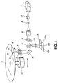
- Fig.1 is a block diagram showing an illustrative construction of an optical recording device according to the present invention.
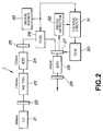
- Fig.2 shows an illustrative arrangement of a UV laser light source constituting the optical recording device.
- Fig.3 shows an illustrative recording state of the optical recording medium.
- Fig.4 is a block diagram showing an illustrative construction of an optical recording/reproducing apparatus according to the present invention.
- Fig.5 is a schematic cross-sectional view of an FZP employed in the optical recording/reproducing apparatus.
- Fig.6 is a graph showing the relation between the diffraction efficiency and the phase depth in the FZP.
- Fig.7 is a graph showing the relation between the aberration of the FZP before correction and that after correction.
- Fig.8 is a schematic view showing the setting of a non-spherical surface in an objective lens of the optical recording/reproducing apparatus.
- Figs.9A, 9B, 9C and 9D are graphs showing the residual wave surface aberration of the wavelength of 532 nm in an objective lens with a numerical aperture of 0.4 after correction with the FZP employed in the optical recording/reproducing apparatus.
- Fig.1 shows, in a block diagram, an illustrative construction of an optical recording device embodying the present invention.
- an ultra-violet laser light source 1 referred to hereinafter as a UV laser light source, capable of radiating a laser light beam of high energy density, is used as a signal recording light source.
- the UV laser light source 1 is a light source radiating a far-ultraviolet laser light by employing generation of fourth harmonics of e.g., a neodymium YAG (Nd:YAG) laser.
- the light beam of the far-UV laser light and the visible laser light, radiated by the UV laser light source 1 is incident on a light modulator 2 by which the UV laser light is modulated in intensity by the subsidiary information which will be explained subsequently.
- the UV laser light beam modulated in intensity by the light modulator 2, is enlarged by lenses 3, 4 and passed through a phase diffraction lattice 5 so as to fall on a semi-transparent mirror or half-mirror 11.
- the optical disc 8 is kept in rotation by a spindle motor 10 which is roughly positioned by e.g. screw feed along the radial direction of the optical disc 8.
- the reflected light of the visible laser light from the surface of the optical disc 8 falls on the mirror 14 via the objective lens 6 so as to be reflected thereby to fall on the half-mirror 11.
- the reflected light incident on the half-mirror 11 is led to a photodetector 13 formed of silicon by a cylindrical lens 12 configured for detecting focusing error signals.
- the photodetector 13 detects the volume of the incident light and outputs electrical signals based upon the incident light volume. De-tracking signals from a guide groove for tracking 9 may be simultaneously detected using output signals from the photodetector 13.
- Focusing error signals and tracking error signals may also be detected from the electrical signals outputted by the photodetector 13. These focusing error signals and tracking error signals are fed back to the biaxial actuator 7 for moving the actuator in a controlled manner so that the UV light spot radiated on the optical disc 8 is focused on the surface of the optical disc 8 at the same time as it is correctly positioned with respect to the guide groove for tracking 9.
- the optical disc 8 has a resin substrate formed of light-transmitting materials, such as polycarbonate or acrylic resins.
- the UV laser light radiated on the optical disc 8 needs to be a laser light beam appropriate for machining the polycarbonate or acrylic resin material. Since polycarbonate and acrylic resins absorb the light having the wavelengths of not more than 290 nm and the light having the wavelengths of not more than 370 nm, respectively, and the UV laser light having the wavelength of not more than 190 nm is absorbed by air, the UV laser light with the wavelength of 190 to 370 nm capable of being satisfactorily absorbed by the substrate of the optical disc 8 and being photodecomposed in a shorter time is preferably employed as the laser light for recording the subsidiary information on the optical disc 8.
- the subsidiary information is recorded using the UV laser light with the wavelength of 266 nm generated by the fourth harmonics generated by the neodymium YAG laser.
- the subsidiary information is recorded as pits on the optical disc 8. Specifically, the portions of the disc irradiated with the UV light spot is removed by ablation for forming the pits.
- the subsidiary information represents the identification information proper to the optical disc 8 and is comprised of micro-codes employed in coding or in a microprocessor.
- the contents of the subsidiary information include the information such as the serial number or pass-word of the optical disc 8.
- the relation between the UV laser light and the size of the recorded pits is explained in detail.
- the size of the pit reproducible with a lens having a wavelength of 780 nm and the numerical aperture of 0.45 is not less than 0.87 ⁇ m. If pits are formed by recording on the optical disc 8 with the ablation mode at s sweep velocity of 1 to 4 m/sec, using the UV laser light, with a wavelength of 266 nm, modulated with a high speed with a pulse width of 20 to 200 ns, and a lens having a numerical aperture of 0.4 or less, the size of the pit thus formed by recording is substantially coincident with the size of the pit reproducible with the UV laser light of the wavelength of 780 nm and with the lens having the numerical aperture of 0.45.
- the visible laser light with a wavelength of 532 nm generated by the UV laser light source 1 is used simultaneously with a UV laser light beam of a wavelength of 266 nm employed for pit recording in consideration of sensitivity, reaction and light-induced damage of the silicon photodetector 13.
- the depth of the tracking guide groove 9 is set to one quarter of the wavelength of 532 nm of the laser light beam so that maximum signal modulation factor will be obtained for the laser light having the wavelength of 532 nm.
- the depth of the tracking guide groove 9 then becomes equal to one-half the wavelength of 266 nm, so that the signal modulation factor is minimized.
- a three-beam method For detecting the tracking errors, a three-beam method is used.
- the three beams in the three-beam method are generated by the phase diffraction lattice 5.
- a synthetic quartz having a high transmission factor of e.g., not lower than 90% for the UV light having the wavelength of 266 nm is employed as a material for the phase diffraction lattice 5.
- the phase depth of the phase diffraction lattice 5 is set to one-half the wavelength of 532 nm of the laser light so that the UV laser light with the wavelength of 266 nm will be transmitted through the lattice 5 and so that the diffraction efficiency will become maximum for the laser light beam with the wavelength of 532 nm. If the scattering caused by the synthetic quartz is disregarded, the phase depth corresponds to one wavelength for the wavelength of the laser light of 266 nm, thus minimizing the diffraction efficiency.
- synthetic quartz needs to be employed not only for the phase diffraction lattice 5 but also for the optical components employed in the optical system excepting a mirror.
- the visible laser light with a wavelength of 532 nm, radiated from the UV laser light source 1, is converted by the phase diffraction lattice 5 into three beams which are then radiated as spots 9a, 9b and 9c on the tracking guide groove 9 formed in the optical disc 8.
- the reflected light of the visible laser light radiated as the spots 9a, 9b and 9c, falls on the photodetector 13 as spots 13a, 13b and 13c and the light volumes of the spots 13a, 13b and 13c are detected by the photodetector 13.
- the existing photodetector is not appropriate for promptly detecting the reflected UV laser light from the optical recording medium, focusing and tracking error signals can be detected speedily and accurately with the present optical recording device employing the visible laser light.
- the existing photodetector is not appropriate for speedily detecting the reflected UV laser light from the optical recording medium
- the focusing and tracking error signals can be detected speedily and accurately with the present optical recording device employing the visible laser light.
- the subsidiary information can be recorded correctly by recording the subsidiary information, with the aid of the UV laser light beam, as focusing control and tracking control are applied with the aid of the visible laser light.
- the UV laser light source 1 is explained in detail.
- a laser diode 21 is a semiconductor laser radiating the laser light of a wavelength of 808 nm for exciting the neodymium YAG laser.
- the laser light from the laser diode 21 falls on an external resonator of the neodymium YAG laser. That is, the laser light falls on a crystal of the neodymium YAG laser 23, as a laser medium, via an optical fiber and a mirror 22, for exciting the neodymium-YAG crystal 23.
- the excited light of the neodymium YAG laser with a wavelength of 1064 nm is radiated from the neodymium-YAG crystal 23.
- the produced second harmonics laser light falls on a non-linear optical crystal element 24 of KTP (KTiOPO 4 ) within an external resonator for generating second harmonics (SHG).
- the laser light of the second harmonics with a wavelength of 532 nm, generated by SHG, is transmitted through a mirror 25 to fall on an electro-optical modulation (EOM) element 26.
- the EOM element 26 is employed for high-speed phase modulation of the fourth harmonics laser light, radiated by the UV laser light source, based upon a signal from a signal source 33.
- the second harmonics laser light from the EOM element 26 falls on an external resonator constituted by mirrors 27, 28 and a non-linear optical crystal element 29 composed of BBO. That is, the second harmonics laser light falls via the mirror 27 on a non-linear optical crystal element 29 via the mirror 27 to generate fourth harmonics laser light with a wavelength of 266 nm by way of fourth harmonics generation.
- the fourth harmonics laser light is radiated to outside via the mirror 28.
- the UV laser light with the wavelength of 266 nm is excited continuously, light intensity modulation may be executed speedily.
- the mode is high in uniformity, the laser light may be condensed easily to a spot with a diameter of not more than 1 ⁇ m.
- the resonant frequency of the external resonator can be swept by driving the mirror in a controlled manner by a voice coil motor 30. That is, the external resonator is excited into operation at a pre-set frequency in a stabilized state. Specifically, the second harmonics laser light outgoing from the EOM element 26 and reflected light by the mirror 27 is incident on a photodetector 32. The photodetector 32 then converts the incident reflected light into an electrical current which is supplied to a lock circuit 31. The lock circuit 31 detects the position of the mirror 27, based upon the electrical current, and negatively feeds back the position signal of the mirror 27 to the voice coil motor (VCM) 30.
- VCM voice coil motor
- the voice coil motor 30 controls the position of the mirror 27, using the position signal transmitted thereto, for locking the resonant frequency of the external resonator.
- Detailed description of the lock circuit is found in JP Patent Kokai Publication HEI-05-243661 corresponding to US Patent 5367531.
- FIG. 3 An illustrative example of the recording state of the subsidiary information by the optical disc is shown in Fig. 3.
- Information signals such as audio, video and data, are recorded in the information recording area 50 on the optical disc 8.
- a lead-in area as an area for recording the information specifying the contents of the information recorded in the information recording area 50.
- a subsidiary information recording area 51 for recording the subsidiary information is provided in the lead-in area, and the identification information proper to the optical disc is recorded in the subsidiary information recording area 51.
- the subsidiary information recording area 51 need not be in the lead-in area and may be in any other area provided that a guide groove for tracking is formed therein. That is, the guide groove for tracking serves as a guide for writing the identification information on the disc.
- the information signals recorded on the optical disc 8 are read out using an optical pickup employing a laser light source such as a semiconductor laser other than the near-infrared laser.
- the recorded subsidiary information may be reproduced using an optical pickup configured for reproducing the information signals.
- the read-out signals of the subsidiary information made up of micro-codes, directly enters a micro-processor, not shown, for discriminating the contents of the information for directly identifying the optical disc.
- the optical disc is mass-produced using a stamper. Specifically, a photoresist film is coated on a glass plate, and signals are recorded thereon by laser light and developed to prepare a master disc. A metal mold (stamper) is then fabricated using the master disc. The optical disc, having the information signals recorded thereon, may be produced in large quantities using this stamper. On the surface of the optical disc carrying the recorded information signals, a metal film for reflection is deposited by vacuum deposition and a protective layer of hard resin is formed thereon to complete a duplicated optical disc.
- the step of recording the subsidiary information on the optical disc using the far-UV laser light radiated from the UV laser light source 1 is carried out before the step of vacuum deposition of the metal film in the above-described method for producing the optical disc.
- an Nd:YAG laser capable of radiating the laser light with a wavelength of 266 nm by fourth harmonics generation from the laser light with a wavelength of 1064 nm is employed as the UV laser light source.
- an Nd:YVO 4 radiating the laser light by fourth harmonics generation of the wavelength of 266 nm from the laser light of the wavelength of 1064 nm
- an Nd:YLF radiating the laser light by fourth harmonics generation of the wavelength of 262 nm from the laser light of the wavelength of 1047 nm
- an Nd:YAP radiating the laser light by fourth harmonics generation of the wavelength of 270 nm from the laser light of the wavelength of 1079 nm.
- an AlGaAs laser source capable of radiating laser light having the wavelength of 0.78 to 0.86 ⁇ m or an InGaAs laser source capable of radiating the laser light having the wavelength of 0.9 to 1.1 ⁇ m may be employed.
- a laser light from a gas laser source such as an Ar laser source capable of radiating laser light of the wavelengths of 0.275 ⁇ m, 0.306 ⁇ m, 0.333 ⁇ m, 0.351 ⁇ m or 0.364 ⁇ m, or a He-Cd laser capable of radiating laser light having the wavelengths of 0.325 ⁇ m or 0.354 ⁇ m.
- KTP or BBO ( ⁇ -BaB 2 O 4 ) is used in the above-described embodiment as the non-linear optical crystal element, LN, QPM, LN, LBO or KN may also be employed.
- the three-beam method is employed in the above-described embodiment for detecting focusing and tracking, it is possible to use a skew beam method or a push-pull method for detecting focusing or tracking, respectively.
- optical recording/reproducing apparatus according to the present invention is now explained.
- the optical recording/reproducing apparatus includes a UV light source 1, an optical pickup 40 for radiating a light beam outgoing from the UV laser light source 1 on the optical disc 8 and transmitting the reflected light from the optical disc 8 to a photodetector 45, and a servo circuit 47 for effecting servo control based upon output signal of the photodetector 45, as shown in Fig.4.
- the parts or components which are the same as those shown in Fig.1 are depicted by the same reference numerals, and the corresponding description is omitted for simplicity.
- the UV laser light source 1 radiates a far-UV laser light in a waveform range of from 200 to 300 nm and a laser light in the visible waveform range of from 400 to 700 nm.
- the laser light of the far-ultraviolet (far-UV) range is set to a wavelength equal to one-half that of the visible light range, as explained previously.
- the optical pickup 40 includes a light intensity modulator 41 for modulating the intensity of the laser light from the UV laser light source 1, and an objective lens 42 for converging the laser light on the optical disc 8.
- the optical pickup also includes a Frenel zone plate (FZP) 43 for converging the laser light of the visible range on the optical disc 8 in a state free from aberration, and a bi-axial actuator 44 for driving the objective lens 42 in a direction along the optical axis and in a direction normal to the optical axis.
- the optical pickup finally includes a photodetector 45 for detecting the light reflected by the optical disc 8 and transmitted through the objective lens 42, and an optical system 46 for conducting the transmitted light to the photodetector 45.
- the laser light outgoing from the UV laser light source 1 is sent to a beam splitter 46c via lenses 46a, 46b constituting a portion of an optical system 46.
- the lens 46a allows the coherent laser light beam with a small beam spot diameter to pass through its focal point and to the lens 46b for setting the beam spot diameter to a pre-set diameter.
- the lens 46b collimates the light from the lens 46a and sends the collimated light to the beam splitter 46c.
- the beam splitter 46c bends the optical axis of the lens 46b by 90° for directing the laser light towards the optical disc 8. This laser light falls on the light intensity modulator 41.
- the light intensity modulator 41 is an optical element exploiting photo-electrical effects by utilizing changes in refractive index caused by impression of electrical voltage. Alternatively, it is an optical element exploiting acousto-optical effects by utilizing the correlation between the sound wave and the light wave passing through the medium.
- the light incident on the light intensity modulator 41 is modulated in accordance with the subsidiary information supplied from outside, and a 0'th order light of the modulated light is taken out.
- the laser light from the light intensity modulator 41 is sent to e.g., the biaxial actuator 44 fitted with the FZP 43 and the objective lens 42 as optical components.
- the biaxial actuator 44 drives the objective lens 42 in a direction indicated by arrows shown in Fig.4, that is in a direction along the optical axis of the objective lens 42 and in a direction normal to the optical axis.
- the FZP 43 is formed of a transparent material exhibiting little absorption in the far-UV range, such as synthesized quartz.
- the FZP 43 is a concentric phase diffraction lattice formed on the substrate surface.
- Fig.5 shows the cross-sectional profile of the phase diffraction lattice.
- the FZP 43 is ideally rectangular in cross-sectional shape and has a constant lattice depth without regard to the radial position, as shown in Fig.5. In addition, the FZP 43 has the lattice period changed depending on the radial position from the center towards the outer rim portion, as shown in Fig.5. The principle of the FZP 43 will be elucidated subsequently.
- the optical disc 8 is irradiated via the objective lens 42 with a laser light corrected by the FZP 43 which functions as a lens in the visible light range and which fails to function as a lens in a band of the far-infra-red range.
- the photodetector 45 converts the detected light into electrical signals which are transmitted to the servo circuit 47.
- the servo circuit 47 finds a signal controlling the operation of the biaxial actuator 44 by the resulting focusing error signals and tracking error signals.
- the biaxial actuator 44 shifts the objective lens 42 in the direction along the optical axis and in the direction normal thereto for minimizing the focusing and tracking errors, as described previously.
- the optical recording/reproducing apparatus exhibits optimum recording characteristics for the far-UV range. Since the information signals are recorded with optimum recording characteristics, and the focusing and tracking control may be carried out with the light in the visible light range, the information signals can be reproduced with optimum playback characteristics.
- a lens formed of a transparent optical material designed to transmit the light in a defined far-UV range is difficult to use directly for the visible range.
- the single lens formed of artificial quartz for the wavelength range of 266 nm is used for the wavelength of 532 nm, the wavelength dispersion of the artificial quartz may be calculated using parameters now to be explained.
- the increase in the focal length of the single lens for the wavelength of 532 nm is 343 ⁇ m.
- a laser light spot with a wavelength of 532 nm is difficult to form on the image plane for the wavelength of 266 nm.
- the single lens is to be used for the wavelength of 532 nm, it is possible to form a spot on the same image plane if a thin-walled lens having a focal length equal to the focal length of the single lens divided by 7.7(%), referred to herein as a second lens, is used in intimate contact with the single lens.
- the focal length of the second lens is 60 to 70 mm.
- the FZP 43 functions effectively as a lens having a constant focal length.
- Fig.6 shows the relation between the phase depth ⁇ , transmittance of the 0'th order light I0 and the diffraction efficiency of the first-order diffracted light I1.
- arrows 2 ⁇ , 4 ⁇ in fig.6 represent the positions of the second harmonics having the wavelength of 532 nm and the fourth harmonics having the wavelength of 266 nm, with the wavelength of 1064 nm being that of the fundamental wave.
- phase depth ⁇ (r) of the FZP 43 is set to 0 and ⁇ for the range shown in the equation (5): 2 m ⁇ - ⁇ /2 ⁇ ( r ) ⁇ 2 m ⁇ + ⁇ /2 and otherwise, respectively, where m is a natural number.
- the coefficients A and B in the equation (7) are fourth-order and sixth-order coefficients of spherical aberration on polynomial expansion of the spherical aberration. These coefficients of spherical aberration may be calculated using a general-purpose optical design program.
- the FZP 43 can be satisfactorily fabricated by correcting the spherical aberration represented by the equation (7).
- the abscissa denotes the relative pupil coordinate of the lens and the ordinate denotes the wave front aberration with the full scale being one wavelength.
- Figs.9A and 9B show aberration characteristics in the tangential direction with the image height being 40 ⁇ m, and aberration characteristics in the sagittal direction with the image height being 40 ⁇ m, respectively.
- Figs.9C and 9D show on-axis aberration characteristics in the tangential direction and on-axis aberration characteristics in the sagittal direction, respectively.
- the rms spherical aberration is 0.002 ⁇ and 0.029 ⁇ on the axis and with the image height of 4040 ⁇ m, respectively. These values are satisfactory as characteristics of the optical recording/reproducing apparatus.
- the rms spherical aberration is not less than 0..07 ⁇ if the numerical aperture is diminished to 0.3.
- the FZP 43 By constructing the FZP 43 as described previously, it may function as a lens in the visible light range, while failing to function as a lens in the far-UV range. Since deterioration in the visible light range in the characteristics of the lens designed for far-UV light may be compensated in this manner, focusing error and tracking error signals may be obtained using the photodetector 45 by correction in the visible light range without deteriorating light condensing characteristics in the far-UV range, so that sufficient recording characteristics may be achieved for recording.
- the present invention provides an optical recording method for recording pre-set information on an optical recording medium in which, when a UV laser light of a wavelength absorbed by the optical recording medium is generated and radiated, the intensity of the UV laser light is modulated for recording the subsidiary information different from the pre-set information recorded in an information recording area of the optical recording medium in an area other than the information recording area, thus enabling identification of each optical recording medium.
- the present invention also provides an optical recording apparatus for recording pre-set information on an optical recording medium having a laser light source for generating a UV laser light of a wavelength absorbed by the optical recording medium and radiating the UV laser light, means for modulating the intensity of the UV laser light from the laser light source, spot position control means for being moved on the optical recording medium for deciding the position of a spot of the UV light beam converged on the optical recording medium, and scanning means for scanning the optical recording medium with the spot.
- the subsidiary information different from the pre-set information recorded in an information recording area of the optical recording medium is recorded in an area other than the information recording area.
- the subsidiary information for identification of each optical recording medium may be recorded on the optical recording medium, so that it can be decided easily whether or not the optical recording medium has been duplicated illicitly, thus prohibiting the optical recording medium from being duplicated illicitly.
- the wavelength of the UV laser light is 190 to 370 nm which is appropriate for machining the recording medium thus facilitating recording of the subsidiary information on the optical recording medium.
- the present invention also provides an optical recording medium having the pre-set information recorded thereon.
- the optical recording medium has an information recording area having the substantial information composed of audio data, video data or character data recorded thereon, and a subsidiary information recording area having the subsidiary information different from the substantial information recorded thereon.
- the subsidiary information is recorded in the subsidiary information recording area by modulating the UV laser light of a wavelength absorbed by the optical recording medium.
- the subsidiary information is recorded in the subsidiary information recording area in the same configuration as that of the substantial information recorded in the information recording area and may be read out easily using an optical pickup as reading means configured for reading out the substantial information.
- the subsidiary information is the identification information proper to each recording medium, it becomes possible to identify each optical recording medium.
- the subsidiary information By recording the subsidiary information on the optical recording medium using the pre-recorded guide pattern for tracking, the subsidiary information may be recorded correctly on the optical recording medium, while the recorded subsidiary information may be read out correctly.
- the guide pattern may be detected using the light of a wavelength different from the wavelength of the laser light, tracking error signals can be detected promptly and accurately, while the subsidiary information may be recorded at a precise position.
Abstract
Description
- This invention relates to an optical recording method for recording signals on a disc-shaped recording medium using a laser light beam, an optical recording device employing the optical recording method, and an optical recording medium on which signals have been recorded by the optical recording device.
- Among the existing types of the disc-shaped optical recording media, there are a phase-change type optical disc and a magneto-optical disc as a write-once or overwrite (reversible) optical disc. Among recording light sources in optical recording devices employing these optical discs, there is known a semiconductor laser for recording signals on the optical disc and for erasing the recorded signals. The laser light beam radiated from the semiconductor laser may be converged on the optical disc as a small-sized spot with a diameter not larger than 1 µm.
- Among replay-only optical discs, there is a CD-ROM employing a compact disc (CD) as a read-only memory. These CD-ROMs can be duplicated in large quantities. It is contemplated at present to record, on the replay-only optical discs capable of being duplicated in large quantities, such as CD-ROMs, information data for identifying these replay-only optical discs, for example, information data for discriminating whether or not the optical disc is an illicitly duplicated disc, in addition to the information signals, such as audio.
- The laser light radiated by the semiconductor laser has a wavelength of 780 nm and is free from ablation. Thus it is not possible to produce a laser light output of an intensity capable of directly recording signals on the replay-only optical disc. Thus, if the identification information is to be recorded on the replay-only optical disc, it is not possible to minutely record the identification information on the replay-only optical disc using the semiconductor laser customarily used as the recording light source.
- In view of the above-depicted status of the art, it is an object of the present invention to provide an optical recording method for recording the identification information proper to an optical medium on the recording medium and for reading out the identification information using an optical pickup configured for reading out the information signals recorded on the optical recording medium, an optical recording device for carrying out the optical recording method, and an optical recording medium having the subsidiary information recorded thereon by the optical recording device.
- An optical recording method for recording pre-set information on an optical recording medium according to the present invention includes the steps of generating a UV laser light of a wavelength absorbed by the optical recording medium and radiating the UV laser light, and modulating the intensity of the UV laser light for recording the subsidiary information different from the pre-set information recorded in an information recording area of the optical recording medium in an area other than the information recording area.
- An optical recording apparatus for recording pre-set information on an optical recording medium according to the present invent ion includes a laser light source for generating a UV laser light of a wavelength absorbed by the optical recording medium and radiating the UV laser light, means for modulating the intensity of the UV laser light from the laser light source, spot position control means for being moved on the optical recording medium for deciding the position of a spot of the UV light beam converged on the optical recording medium, and scanning means for scanning the optical recording medium with the spot. The subsidiary information different from the pre-set information recorded in an information recording area of the optical recording medium is recorded in an area other than the information recording area.
- An optical recording medium having the pre-set information recorded thereon according to the present invention includes an information recording area having the substantial information composed of audio data, video data or character data recorded thereon, and a subsidiary information recording area having the subsidiary information different from the substantial information recorded thereon. The subsidiary information is recorded in the subsidiary information recording area by modulating the UV laser light of a wavelength absorbed by the optical recording medium.
- The wavelength of the UV laser light may be 190 to 370 nm.
- The UV laser light may be the far-ultraviolet laser light generated by fourth harmonics generation by a neodymium YAG (Nd:YAG) laser, an Nd:YVO4 laser, an Nd:YLF laser or a YAP laser.
- The UV laser light may be a laser light from an Ar laser or a He-Cd laser.
- The subsidiary information may be the identification information proper to each optical recording medium.
- The subsidiary information may be recorded on the optical recording medium using a pre-recorded guide pattern for tracking.
- If tracking is done using the guide pattern, the guide pattern may be detected using the light of a wavelength different from that of the laser light.
- According to the present invention, since the identification information proper to each optical recording medium is recorded as the subsidiary information in the subsidiary information recording area, having the tracking guide pattern pre-recorded thereon, using the UV laser light, as tracking is done in accordance with the guide pattern with the aid of the light of a wavelength different from that of the UV laser light, the mass-produced optical recording media may be discriminated from one another.
- Fig.1 is a block diagram showing an illustrative construction of an optical recording device according to the present invention.
- Fig.2 shows an illustrative arrangement of a UV laser light source constituting the optical recording device.
- Fig.3 shows an illustrative recording state of the optical recording medium.
- Fig.4 is a block diagram showing an illustrative construction of an optical recording/reproducing apparatus according to the present invention.
- Fig.5 is a schematic cross-sectional view of an FZP employed in the optical recording/reproducing apparatus.
- Fig.6 is a graph showing the relation between the diffraction efficiency and the phase depth in the FZP.
- Fig.7 is a graph showing the relation between the aberration of the FZP before correction and that after correction.
- Fig.8 is a schematic view showing the setting of a non-spherical surface in an objective lens of the optical recording/reproducing apparatus.
- Figs.9A, 9B, 9C and 9D are graphs showing the residual wave surface aberration of the wavelength of 532 nm in an objective lens with a numerical aperture of 0.4 after correction with the FZP employed in the optical recording/reproducing apparatus.
- Referring to the drawings, preferred embodiments of the present invention will be explained in detail. Fig.1 shows, in a block diagram, an illustrative construction of an optical recording device embodying the present invention.
- In the optical recording device of the illustrated embodiment, an ultra-violet
laser light source 1, referred to hereinafter as a UV laser light source, capable of radiating a laser light beam of high energy density, is used as a signal recording light source. Specifically, the UVlaser light source 1 is a light source radiating a far-ultraviolet laser light by employing generation of fourth harmonics of e.g., a neodymium YAG (Nd:YAG) laser. The light beam of the far-UV laser light and the visible laser light, radiated by the UVlaser light source 1, is incident on alight modulator 2 by which the UV laser light is modulated in intensity by the subsidiary information which will be explained subsequently. - The UV laser light beam, modulated in intensity by the
light modulator 2, is enlarged bylenses 3, 4 and passed through aphase diffraction lattice 5 so as to fall on a semi-transparent mirror or half-mirror 11. The UV laser light beam, transmitted through thehalf mirror 11, is reflected by amirror 14 so as to be converged by anobjective lens 6 mounted on a bi-axial actuator 7 so as to be radiated as a light spot on the surface of anoptical disc 8. - The
optical disc 8 is kept in rotation by aspindle motor 10 which is roughly positioned by e.g. screw feed along the radial direction of theoptical disc 8. - The reflected light of the visible laser light from the surface of the
optical disc 8 falls on themirror 14 via theobjective lens 6 so as to be reflected thereby to fall on the half-mirror 11. The reflected light incident on the half-mirror 11 is led to aphotodetector 13 formed of silicon by acylindrical lens 12 configured for detecting focusing error signals. Thephotodetector 13 detects the volume of the incident light and outputs electrical signals based upon the incident light volume. De-tracking signals from a guide groove for tracking 9 may be simultaneously detected using output signals from thephotodetector 13. - Focusing error signals and tracking error signals may also be detected from the electrical signals outputted by the
photodetector 13. These focusing error signals and tracking error signals are fed back to the biaxial actuator 7 for moving the actuator in a controlled manner so that the UV light spot radiated on theoptical disc 8 is focused on the surface of theoptical disc 8 at the same time as it is correctly positioned with respect to the guide groove for tracking 9. - The
optical disc 8 has a resin substrate formed of light-transmitting materials, such as polycarbonate or acrylic resins. Thus the UV laser light radiated on theoptical disc 8 needs to be a laser light beam appropriate for machining the polycarbonate or acrylic resin material. Since polycarbonate and acrylic resins absorb the light having the wavelengths of not more than 290 nm and the light having the wavelengths of not more than 370 nm, respectively, and the UV laser light having the wavelength of not more than 190 nm is absorbed by air, the UV laser light with the wavelength of 190 to 370 nm capable of being satisfactorily absorbed by the substrate of theoptical disc 8 and being photodecomposed in a shorter time is preferably employed as the laser light for recording the subsidiary information on theoptical disc 8. Thus, in the present embodiment, the subsidiary information is recorded using the UV laser light with the wavelength of 266 nm generated by the fourth harmonics generated by the neodymium YAG laser. - By this UV laser light, the subsidiary information is recorded as pits on the
optical disc 8. Specifically, the portions of the disc irradiated with the UV light spot is removed by ablation for forming the pits. - The subsidiary information represents the identification information proper to the
optical disc 8 and is comprised of micro-codes employed in coding or in a microprocessor. The contents of the subsidiary information include the information such as the serial number or pass-word of theoptical disc 8. - The relation between the UV laser light and the size of the recorded pits is explained in detail. The size of the pit reproducible with a lens having a wavelength of 780 nm and the numerical aperture of 0.45 is not less than 0.87 µm. If pits are formed by recording on the
optical disc 8 with the ablation mode at s sweep velocity of 1 to 4 m/sec, using the UV laser light, with a wavelength of 266 nm, modulated with a high speed with a pulse width of 20 to 200 ns, and a lens having a numerical aperture of 0.4 or less, the size of the pit thus formed by recording is substantially coincident with the size of the pit reproducible with the UV laser light of the wavelength of 780 nm and with the lens having the numerical aperture of 0.45. - For detecting the focusing error signals and tracking error signals using the reflected light from the
optical disc 8, the visible laser light with a wavelength of 532 nm generated by the UVlaser light source 1 is used simultaneously with a UV laser light beam of a wavelength of 266 nm employed for pit recording in consideration of sensitivity, reaction and light-induced damage of thesilicon photodetector 13. - The depth of the tracking guide groove 9 is set to one quarter of the wavelength of 532 nm of the laser light beam so that maximum signal modulation factor will be obtained for the laser light having the wavelength of 532 nm. The depth of the tracking guide groove 9 then becomes equal to one-half the wavelength of 266 nm, so that the signal modulation factor is minimized.
- The detection of tracking error signal in the tracking operation is explained.
- For detecting the tracking errors, a three-beam method is used. The three beams in the three-beam method are generated by the
phase diffraction lattice 5. Thus a synthetic quartz having a high transmission factor of e.g., not lower than 90% for the UV light having the wavelength of 266 nm is employed as a material for thephase diffraction lattice 5. The phase depth of thephase diffraction lattice 5 is set to one-half the wavelength of 532 nm of the laser light so that the UV laser light with the wavelength of 266 nm will be transmitted through thelattice 5 and so that the diffraction efficiency will become maximum for the laser light beam with the wavelength of 532 nm. If the scattering caused by the synthetic quartz is disregarded, the phase depth corresponds to one wavelength for the wavelength of the laser light of 266 nm, thus minimizing the diffraction efficiency. - Although scattering by the synthetic quartz cannot in effect be disregarded, more importance is attached to the minimum diffraction efficiency for the wavelength of 266 nm. It is noted that synthetic quartz needs to be employed not only for the
phase diffraction lattice 5 but also for the optical components employed in the optical system excepting a mirror. - The visible laser light, with a wavelength of 532 nm, radiated from the UV
laser light source 1, is converted by thephase diffraction lattice 5 into three beams which are then radiated asspots 9a, 9b and 9c on the tracking guide groove 9 formed in theoptical disc 8. The reflected light of the visible laser light, radiated as thespots 9a, 9b and 9c, falls on thephotodetector 13 asspots spots photodetector 13. Although the existing photodetector is not appropriate for promptly detecting the reflected UV laser light from the optical recording medium, focusing and tracking error signals can be detected speedily and accurately with the present optical recording device employing the visible laser light. - Meanwhile, by arranging a pair of four-quadrant photodetectors in register with the
light spots photodetector 13 associated with thelight spots 9a, 9c formed by the ±1st order diffracted light, it becomes possible to simultaneously detect focusing error signals and tracking error signal by the astigmatic method employing a cylindrical lens and by the three-beam method, respectively. - That is, although the existing photodetector is not appropriate for speedily detecting the reflected UV laser light from the optical recording medium, the focusing and tracking error signals can be detected speedily and accurately with the present optical recording device employing the visible laser light. In other words, the subsidiary information can be recorded correctly by recording the subsidiary information, with the aid of the UV laser light beam, as focusing control and tracking control are applied with the aid of the visible laser light.
- Referring to Fig.2, the UV
laser light source 1 is explained in detail. - A
laser diode 21 is a semiconductor laser radiating the laser light of a wavelength of 808 nm for exciting the neodymium YAG laser. The laser light from thelaser diode 21 falls on an external resonator of the neodymium YAG laser. That is, the laser light falls on a crystal of theneodymium YAG laser 23, as a laser medium, via an optical fiber and amirror 22, for exciting the neodymium-YAG crystal 23. Thus the excited light of the neodymium YAG laser with a wavelength of 1064 nm is radiated from the neodymium-YAG crystal 23. - The produced second harmonics laser light falls on a non-linear
optical crystal element 24 of KTP (KTiOPO4) within an external resonator for generating second harmonics (SHG). The laser light of the second harmonics, with a wavelength of 532 nm, generated by SHG, is transmitted through amirror 25 to fall on an electro-optical modulation (EOM)element 26. TheEOM element 26 is employed for high-speed phase modulation of the fourth harmonics laser light, radiated by the UV laser light source, based upon a signal from asignal source 33. - The second harmonics laser light from the
EOM element 26 falls on an external resonator constituted bymirrors optical crystal element 29 composed of BBO. That is, the second harmonics laser light falls via themirror 27 on a non-linearoptical crystal element 29 via themirror 27 to generate fourth harmonics laser light with a wavelength of 266 nm by way of fourth harmonics generation. The fourth harmonics laser light is radiated to outside via themirror 28. - Since the UV laser light with the wavelength of 266 nm is excited continuously, light intensity modulation may be executed speedily. In addition, since the mode is high in uniformity, the laser light may be condensed easily to a spot with a diameter of not more than 1 µm.
- The resonant frequency of the external resonator can be swept by driving the mirror in a controlled manner by a
voice coil motor 30. That is, the external resonator is excited into operation at a pre-set frequency in a stabilized state. Specifically, the second harmonics laser light outgoing from theEOM element 26 and reflected light by themirror 27 is incident on aphotodetector 32. Thephotodetector 32 then converts the incident reflected light into an electrical current which is supplied to alock circuit 31. Thelock circuit 31 detects the position of themirror 27, based upon the electrical current, and negatively feeds back the position signal of themirror 27 to the voice coil motor (VCM) 30. Thevoice coil motor 30 controls the position of themirror 27, using the position signal transmitted thereto, for locking the resonant frequency of the external resonator. Detailed description of the lock circuit is found in JP Patent Kokai Publication HEI-05-243661 corresponding to US Patent 5367531. - An illustrative example of the recording state of the subsidiary information by the optical disc is shown in Fig. 3.
- Information signals, such as audio, video and data, are recorded in the
information recording area 50 on theoptical disc 8. On the inner peripheral side of theinformation recording area 50, there is provided a lead-in area as an area for recording the information specifying the contents of the information recorded in theinformation recording area 50. A subsidiaryinformation recording area 51 for recording the subsidiary information is provided in the lead-in area, and the identification information proper to the optical disc is recorded in the subsidiaryinformation recording area 51. - The subsidiary
information recording area 51 need not be in the lead-in area and may be in any other area provided that a guide groove for tracking is formed therein. That is, the guide groove for tracking serves as a guide for writing the identification information on the disc. - The information signals recorded on the
optical disc 8 are read out using an optical pickup employing a laser light source such as a semiconductor laser other than the near-infrared laser. The recorded subsidiary information may be reproduced using an optical pickup configured for reproducing the information signals. The read-out signals of the subsidiary information, made up of micro-codes, directly enters a micro-processor, not shown, for discriminating the contents of the information for directly identifying the optical disc. - The optical disc is mass-produced using a stamper. Specifically, a photoresist film is coated on a glass plate, and signals are recorded thereon by laser light and developed to prepare a master disc. A metal mold (stamper) is then fabricated using the master disc. The optical disc, having the information signals recorded thereon, may be produced in large quantities using this stamper. On the surface of the optical disc carrying the recorded information signals, a metal film for reflection is deposited by vacuum deposition and a protective layer of hard resin is formed thereon to complete a duplicated optical disc.
- The step of recording the subsidiary information on the optical disc using the far-UV laser light radiated from the UV
laser light source 1 is carried out before the step of vacuum deposition of the metal film in the above-described method for producing the optical disc. - In the above-described embodiment, an Nd:YAG laser capable of radiating the laser light with a wavelength of 266 nm by fourth harmonics generation from the laser light with a wavelength of 1064 nm is employed as the UV laser light source. As alternative solid lasers, use may be made of an Nd:YVO4 radiating the laser light by fourth harmonics generation of the wavelength of 266 nm from the laser light of the wavelength of 1064 nm, an Nd:YLF radiating the laser light by fourth harmonics generation of the wavelength of 262 nm from the laser light of the wavelength of 1047 nm and an Nd:YAP radiating the laser light by fourth harmonics generation of the wavelength of 270 nm from the laser light of the wavelength of 1079 nm. Alternatively, as the semiconductor laser light source capable of directly radiating a quadrupled wave, an AlGaAs laser source capable of radiating laser light having the wavelength of 0.78 to 0.86 µm or an InGaAs laser source capable of radiating the laser light having the wavelength of 0.9 to 1.1 µm may be employed. It is also possible to use a laser light from a gas laser source, such as an Ar laser source capable of radiating laser light of the wavelengths of 0.275 µm, 0.306 µm, 0.333 µm, 0.351 µm or 0.364 µm, or a He-Cd laser capable of radiating laser light having the wavelengths of 0.325 µm or 0.354 µm.
- Although KTP or BBO (β-BaB2O4) is used in the above-described embodiment as the non-linear optical crystal element, LN, QPM, LN, LBO or KN may also be employed.
- In addition, although the three-beam method is employed in the above-described embodiment for detecting focusing and tracking, it is possible to use a skew beam method or a push-pull method for detecting focusing or tracking, respectively.
- The optical recording/reproducing apparatus according to the present invention is now explained.
- The optical recording/reproducing apparatus includes a
UV light source 1, anoptical pickup 40 for radiating a light beam outgoing from the UVlaser light source 1 on theoptical disc 8 and transmitting the reflected light from theoptical disc 8 to aphotodetector 45, and aservo circuit 47 for effecting servo control based upon output signal of thephotodetector 45, as shown in Fig.4. The parts or components which are the same as those shown in Fig.1 are depicted by the same reference numerals, and the corresponding description is omitted for simplicity. - The UV
laser light source 1 radiates a far-UV laser light in a waveform range of from 200 to 300 nm and a laser light in the visible waveform range of from 400 to 700 nm. The laser light of the far-ultraviolet (far-UV) range is set to a wavelength equal to one-half that of the visible light range, as explained previously. - Referring to Fig.4, the
optical pickup 40 includes alight intensity modulator 41 for modulating the intensity of the laser light from the UVlaser light source 1, and anobjective lens 42 for converging the laser light on theoptical disc 8. The optical pickup also includes a Frenel zone plate (FZP) 43 for converging the laser light of the visible range on theoptical disc 8 in a state free from aberration, and abi-axial actuator 44 for driving theobjective lens 42 in a direction along the optical axis and in a direction normal to the optical axis. The optical pickup finally includes aphotodetector 45 for detecting the light reflected by theoptical disc 8 and transmitted through theobjective lens 42, and anoptical system 46 for conducting the transmitted light to thephotodetector 45. - The laser light outgoing from the UV
laser light source 1 is sent to abeam splitter 46c vialenses optical system 46. Thelens 46a allows the coherent laser light beam with a small beam spot diameter to pass through its focal point and to thelens 46b for setting the beam spot diameter to a pre-set diameter. Thelens 46b collimates the light from thelens 46a and sends the collimated light to thebeam splitter 46c. - The
beam splitter 46c bends the optical axis of thelens 46b by 90° for directing the laser light towards theoptical disc 8. This laser light falls on thelight intensity modulator 41. - The
light intensity modulator 41 is an optical element exploiting photo-electrical effects by utilizing changes in refractive index caused by impression of electrical voltage. Alternatively, it is an optical element exploiting acousto-optical effects by utilizing the correlation between the sound wave and the light wave passing through the medium. The light incident on thelight intensity modulator 41 is modulated in accordance with the subsidiary information supplied from outside, and a 0'th order light of the modulated light is taken out. - The laser light from the
light intensity modulator 41 is sent to e.g., thebiaxial actuator 44 fitted with theFZP 43 and theobjective lens 42 as optical components. Thebiaxial actuator 44 drives theobjective lens 42 in a direction indicated by arrows shown in Fig.4, that is in a direction along the optical axis of theobjective lens 42 and in a direction normal to the optical axis. - The
FZP 43 is formed of a transparent material exhibiting little absorption in the far-UV range, such as synthesized quartz. TheFZP 43 is a concentric phase diffraction lattice formed on the substrate surface. Fig.5 shows the cross-sectional profile of the phase diffraction lattice. - The
FZP 43 is ideally rectangular in cross-sectional shape and has a constant lattice depth without regard to the radial position, as shown in Fig.5. In addition, theFZP 43 has the lattice period changed depending on the radial position from the center towards the outer rim portion, as shown in Fig.5. The principle of theFZP 43 will be elucidated subsequently. - The
optical disc 8 is irradiated via theobjective lens 42 with a laser light corrected by theFZP 43 which functions as a lens in the visible light range and which fails to function as a lens in a band of the far-infra-red range. - The
photodetector 45 converts the detected light into electrical signals which are transmitted to theservo circuit 47. Theservo circuit 47 finds a signal controlling the operation of thebiaxial actuator 44 by the resulting focusing error signals and tracking error signals. - The
biaxial actuator 44 shifts theobjective lens 42 in the direction along the optical axis and in the direction normal thereto for minimizing the focusing and tracking errors, as described previously. Thus the optical recording/reproducing apparatus exhibits optimum recording characteristics for the far-UV range. Since the information signals are recorded with optimum recording characteristics, and the focusing and tracking control may be carried out with the light in the visible light range, the information signals can be reproduced with optimum playback characteristics. - The principle of the
FZP 43 is explained. - It is known that a lens formed of a transparent optical material designed to transmit the light in a defined far-UV range is difficult to use directly for the visible range. For example, if the single lens formed of artificial quartz for the wavelength range of 266 nm is used for the wavelength of 532 nm, the wavelength dispersion of the artificial quartz may be calculated using parameters now to be explained.
- As for the wavelength-dependent parameters, the refractive index N is such that

- The increase in the focal length for the wavelength 532 nm of the single lens, caused by such difference in the refractive index, is obtained from the equation (1):

- Thus, with the focal length of 4.5 mm of the single lens for the wavelength of 266 nm, the increase in the focal length of the single lens for the wavelength of 532 nm is 343 µm. Thus it is seen that a laser light spot with a wavelength of 532 nm is difficult to form on the image plane for the wavelength of 266 nm.
- Thus, if the single lens is to be used for the wavelength of 532 nm, it is possible to form a spot on the same image plane if a thin-walled lens having a focal length equal to the focal length of the single lens divided by 7.7(%), referred to herein as a second lens, is used in intimate contact with the single lens. In effect, given the second lens having a constant thickness, the focal length of the second lens is 60 to 70 mm.
- If the second lens is constituted by the
FZP 43 as shown in Fig.5, and the lattice has a pre-set depth t equal to 532 nm, the phase depth φ for the wavelength λ = 266 nm is equal to 2π, as shown by the equation (2):
- That is, the diffraction efficiency at the wavelength λ=266 nm of the
FZP 43 becomes minimum such that the FZP fails to function as a lens. - On the other hand, the phase depth φ becomes equal to 0.92π as indicated by the equation (3):

- That is, in the vicinity of φ=π where the diffraction efficiency becomes maximum, the
FZP 43 functions effectively as a lens having a constant focal length. - Fig.6 shows the relation between the phase depth φ, transmittance of the 0'th order light I0 and the diffraction efficiency of the first-order diffracted light I1.
- In Fig.6, arrows 2ω, 4ω in fig.6 represent the positions of the second harmonics having the wavelength of 532 nm and the fourth harmonics having the wavelength of 266 nm, with the wavelength of 1064 nm being that of the fundamental wave. The phase depth φ=2π for the fourth harmonics of the wavelength of 266 nm is naturally equivalent to φ=0.
- If, with the
FZP 43 having the focal length f, the radius vector is r and the coefficient is a, the phase depth φ(r) of the wave surface is given by the equation (4):
- The phase depth φ(r) of the
FZP 43 is set to 0 and φ for the range shown in the equation (5):
- The relation between the coefficient a and the focal length f is represented by the equation (6):

- For preparing the
FZP 43 with the focal length f=65 mm for the wavelength λ=532 nm, it suffices to set so that a=28.92π from the equation (6). - For producing the
FZP 43 having the focal length f=65 mm, for example, for the wavelength λ=532 nm, it suffices to set a=28.92π from the equation (6). - With a lens construction comprised of the
objective lens 42 having no aberration for the wavelength λ=532 nm, the spherical aberration produced on using the lens construction for the wavelength λ=532 nm is represented by the equation (7):
- The coefficients A and B in the equation (7) are fourth-order and sixth-order coefficients of spherical aberration on polynomial expansion of the spherical aberration. These coefficients of spherical aberration may be calculated using a general-purpose optical design program.
- The phase depth φ(r) of the wave surface represented by the equation (4) may be modified as shown in the equation (8):

- Specifically, since the amount of the spherical aberration in the vicinity of the pupil for the numerical aperture of the
objective lens 42 of 0.4 is on the order of 3λ, theFZP 43 can be satisfactorily fabricated by correcting the spherical aberration represented by the equation (7). - The relation of φ(r) with respect to the radius vector r may be represented by a broken line specifying the absence of aberration and a solid line representing the post-correction state. It is seen from Fig.7 that the amount of correction is increased outwardly from r=1 mm as shown for example in Fig.7.
- An aspherical lens with the numerical aperture of 0.4, which should be corrected by the
FZP 43, is represented as shown for example in Fig.8. The design dimensions of the aspherical lens are as shown in Table 1. It is noted that the focal length and the residual wave front aberration for the wavelength λ=266 nm are also shown in Fig.8.TABLE 1 radius of curvature thickness refractive index aspherical coefficient article surface ∞ ∞ first surface 2.50144 2.500000 1.499679 (synthetic quartz) K:-0.177604 A:-0.208109E -02 B:-0.244232E -03 C: 0.000000E +00 D: 0.000000E +00 second surface -14.83532 3.001502 1 (air) K:-175. 128050 A:-0.166 201E-02 B:-0.103 811E+00 C: 0.000000 E-00 D: 0.000000 E+00 image surface ∞ -0.00006 focal length: 45 mm (λ=266 nm) 4.8675 (λ=532 nm)
wave front aberration on axis: 0.006 rmsλ
wave front aberration outside axis: 0.016 rmsλ - Figs.9A and 9B show the residual wave front aberration on allowing the laser light with the wavelength λ=532 nm to fall on the
objective lens 42, with the numerical aperture of 0.4, as corrected with theFZP 43. In these figures, the abscissa denotes the relative pupil coordinate of the lens and the ordinate denotes the wave front aberration with the full scale being one wavelength. - Figs.9A and 9B show aberration characteristics in the tangential direction with the image height being 40 µm, and aberration characteristics in the sagittal direction with the image height being 40 µm, respectively. On the other hand, Figs.9C and 9D show on-axis aberration characteristics in the tangential direction and on-axis aberration characteristics in the sagittal direction, respectively.
- The rms spherical aberration is 0.002 λ and 0.029 λ on the axis and with the image height of 4040 µm, respectively. These values are satisfactory as characteristics of the optical recording/reproducing apparatus. Before correction of the spherical aberration, the rms spherical aberration is not less than 0..07 λ if the numerical aperture is diminished to 0.3.
- By constructing the
FZP 43 as described previously, it may function as a lens in the visible light range, while failing to function as a lens in the far-UV range. Since deterioration in the visible light range in the characteristics of the lens designed for far-UV light may be compensated in this manner, focusing error and tracking error signals may be obtained using thephotodetector 45 by correction in the visible light range without deteriorating light condensing characteristics in the far-UV range, so that sufficient recording characteristics may be achieved for recording. - It will be apparent from the above description that the present invention provides an optical recording method for recording pre-set information on an optical recording medium in which, when a UV laser light of a wavelength absorbed by the optical recording medium is generated and radiated, the intensity of the UV laser light is modulated for recording the subsidiary information different from the pre-set information recorded in an information recording area of the optical recording medium in an area other than the information recording area, thus enabling identification of each optical recording medium.
- The present invention also provides an optical recording apparatus for recording pre-set information on an optical recording medium having a laser light source for generating a UV laser light of a wavelength absorbed by the optical recording medium and radiating the UV laser light, means for modulating the intensity of the UV laser light from the laser light source, spot position control means for being moved on the optical recording medium for deciding the position of a spot of the UV light beam converged on the optical recording medium, and scanning means for scanning the optical recording medium with the spot. The subsidiary information different from the pre-set information recorded in an information recording area of the optical recording medium is recorded in an area other than the information recording area. Thus the subsidiary information for identification of each optical recording medium may be recorded on the optical recording medium, so that it can be decided easily whether or not the optical recording medium has been duplicated illicitly, thus prohibiting the optical recording medium from being duplicated illicitly.
- The wavelength of the UV laser light is 190 to 370 nm which is appropriate for machining the recording medium thus facilitating recording of the subsidiary information on the optical recording medium.
- The present invention also provides an optical recording medium having the pre-set information recorded thereon. The optical recording medium has an information recording area having the substantial information composed of audio data, video data or character data recorded thereon, and a subsidiary information recording area having the subsidiary information different from the substantial information recorded thereon. The subsidiary information is recorded in the subsidiary information recording area by modulating the UV laser light of a wavelength absorbed by the optical recording medium. Thus the subsidiary information is recorded in the subsidiary information recording area in the same configuration as that of the substantial information recorded in the information recording area and may be read out easily using an optical pickup as reading means configured for reading out the substantial information.
- Since the subsidiary information is the identification information proper to each recording medium, it becomes possible to identify each optical recording medium.
- By recording the subsidiary information on the optical recording medium using the pre-recorded guide pattern for tracking, the subsidiary information may be recorded correctly on the optical recording medium, while the recorded subsidiary information may be read out correctly.
- Since the guide pattern may be detected using the light of a wavelength different from the wavelength of the laser light, tracking error signals can be detected promptly and accurately, while the subsidiary information may be recorded at a precise position.
Claims (31)
- An optical recording method for recording pre-set information on an optical recording medium, comprising the steps of:generating a UV laser light of a wavelength absorbed by said optical recording medium and radiating said UV laser light; andmodulating the intensity of said UV laser light for recording the subsidiary information different from said pre-set information recorded in an information recording area of said optical recording medium in an area other than said information recording area.
- The optical recording method as claimed in claim 1 wherein said UV laser light has a wavelength of 190 to 370 nm.
- The optical recording method as claimed in claim 1 wherein said UV laser light is the far-infrared laser light generated by fourth harmonics generation of a neodymium YAG (Nd:YAG) laser.
- The optical recording method as claimed in claim 1 wherein said subsidiary information is the identification information proper to the optical recording medium.
- The optical recording method as claimed in claim 1 wherein said subsidiary information is recorded in said optical recording medium using a pre-recorded guide pattern for tracking.
- The optical recording method as claimed in claim 5 wherein said guide pattern is detected using the light having a wavelength different from that of the UV laser light when tracking is done using said guide pattern.
- The optical recording method as claimed in claim 1 wherein said UV laser light is the far-ultraviolet laser light generated by fourth harmonics generation of a Nd:YVO4 laser.
- The optical recording method as claimed in claim 1 wherein said UV laser light is the far-ultraviolet laser light generated by fourth harmonics generation of a Nd:YLF laser.
- The optical recording method as claimed in claim 1 wherein said UV laser light is the far-ultraviolet laser light generated by fourth harmonics generation of a Nd:YAP laser.
- The optical recording method as claimed in claim 1 wherein said UV laser light is the laser light of a wavelength of 0.78 to 0.86 µm from an INGaAs laser.
- The optical recording method as claimed in claim 1 wherein said UV laser light is the laser light of a wavelength of 0.9 to 1.1 µm from an INGaAs laser.
- The optical recording method as claimed in claim 1 wherein said UV laser light is the laser light from an Ar laser.
- The optical recording method as claimed in claim 1 wherein said UV laser light is the laser light from an He-Cd laser.
- An optical recording apparatus for recording pre-set information on an optical recording medium, comprising;a laser light source for generating a UV laser light of a wavelength absorbed by said optical recording medium and radiating said UV laser light;means for modulating the intensity of the UV laser light from said laser light source; spot position control means for being moved on said optical recording medium for deciding the position of a spot of the UV light beam converged on said optical recording medium; andscanning means for scanning said optical recording medium with said spot; whereinthe subsidiary information different from said pre-set information recorded in an information recording area of said optical recording medium is recorded in an area other than said information recording area.
- The optical recording apparatus as claimed in claim 14 wherein said UV laser light has a wavelength of 190 to 370 nm.
- The optical recording apparatus as claimed in claim 14 wherein said UV laser light is the far-ultraviolet laser light generated by fourth harmonics generation of a neodymium YAG (Nd:YAG) laser.
- The optical recording apparatus as claimed in claim 14 wherein said subsidiary information is the identification information proper to the optical recording medium.
- The optical recording apparatus as claimed in claim 14 wherein said subsidiary information is recorded in said optical recording medium using a pre-recorded guide pattern for tracking.
- The optical recording apparatus as claimed in claim 18 wherein said guide pattern is detected using the light having a wavelength different from that of the UV laser light when tracking is done using said guide pattern.
- The optical recording apparatus as claimed in claim 14 wherein said UV laser light is the far-ultraviolet laser light generated by fourth harmonics generation of a Nd:YVO4 laser.
- The optical recording apparatus as claimed in claim 14 wherein said UV laser light is the far-ultraviolet laser light generated by fourth harmonics generation of a Nd:YLF laser.
- The optical recording apparatus as claimed in claim 14 wherein said UV laser light is the far-ultraviolet laser light generated by fourth harmonics generation of a Nd:YAP laser.
- The optical recording apparatus as claimed in claim 14 wherein said UV laser light is the laser light from an AlGaAs laser.
- The optical recording apparatus as claimed in claim 14 wherein said UV laser light is the laser light from an INGaAs laser.
- The optical recording apparatus as claimed in claim 14 wherein said UV laser light is the laser light from an Ar laser.
- The optical recording apparatus as claimed in claim 14 wherein said UV laser light is the laser light from a He-Cd laser.
- An optical recording medium having the pre-set information recorded thereon, comprising:an information recording area having the substantial information composed of audio data, video data or character data recorded thereon; anda subsidiary information recording area having the subsidiary information different from said substantial information recorded thereon; whereinsaid subsidiary information is recorded in said subsidiary information recording area by modulating the UV laser light of a wavelength absorbed by said optical recording medium.
- The optical recording medium as claimed in claim 27 wherein said subsidiary information is the identification information proper to the optical recording medium.
- The optical recording medium as claimed in claim 27 wherein a guide groove for tracking is pre-recorded in said subsidiary information recording area and wherein said subsidiary information is recorded using said guide pattern.
- The optical recording medium as claimed in claim 29 wherein, if tracking is done using said guide pattern, said guide pattern is detected using the light of a wavelength different from the wavelength of said UV laser light.
- The optical recording medium as claimed in claim 27 wherein said subsidiary information is composed of codes or micro-codes.
Applications Claiming Priority (4)
| Application Number | Priority Date | Filing Date | Title |
|---|---|---|---|
| JP23121594A JP3707812B2 (en) | 1994-09-27 | 1994-09-27 | Optical recording method, optical recording apparatus, and optical recording medium |
| JP231215/94 | 1994-09-27 | ||
| JP23121594 | 1994-09-27 | ||
| PCT/JP1995/001895 WO1996010250A1 (en) | 1994-09-27 | 1995-09-20 | Optical recording method, optical recording apparatus and optical recording medium |
Publications (3)
| Publication Number | Publication Date |
|---|---|
| EP0731454A1 true EP0731454A1 (en) | 1996-09-11 |
| EP0731454A4 EP0731454A4 (en) | 1997-02-26 |
| EP0731454B1 EP0731454B1 (en) | 2001-03-28 |
Family
ID=16920137
Family Applications (1)
| Application Number | Title | Priority Date | Filing Date |
|---|---|---|---|
| EP95932193A Expired - Lifetime EP0731454B1 (en) | 1994-09-27 | 1995-09-20 | Optical recording method, optical recording apparatus and optical recording medium |
Country Status (8)
| Country | Link |
|---|---|
| US (1) | US5822287A (en) |
| EP (1) | EP0731454B1 (en) |
| JP (1) | JP3707812B2 (en) |
| KR (1) | KR100377281B1 (en) |
| CN (1) | CN1083132C (en) |
| DE (1) | DE69520487T2 (en) |
| MY (1) | MY113761A (en) |
| WO (1) | WO1996010250A1 (en) |
Cited By (5)
| Publication number | Priority date | Publication date | Assignee | Title |
|---|---|---|---|---|
| WO2002082429A2 (en) * | 2000-12-14 | 2002-10-17 | Ecd Systems, Inc. | Systems and methods for optical media modification |
| WO2004032128A1 (en) * | 2002-10-02 | 2004-04-15 | Koninklijke Philips Electronics N.V. | Optical record carrier for use with uv laser beam |
| WO2005088615A1 (en) * | 2004-03-09 | 2005-09-22 | Koninklijke Philips Electronics N.V. | Optical recording disc adapted to storing data using an ultra-violet laser source |
| WO2006120599A1 (en) * | 2005-05-11 | 2006-11-16 | Koninklijke Philips Electronics N.V. | Objective system for an optical scanning device for ultraviolet and/or deep-ultraviolet wavelengths |
| CN100440341C (en) * | 2004-05-25 | 2008-12-03 | 船井电机株式会社 | Optical pickup device |
Families Citing this family (15)
| Publication number | Priority date | Publication date | Assignee | Title |
|---|---|---|---|---|
| JPH10302321A (en) * | 1997-04-30 | 1998-11-13 | Sony Corp | Optical disk and manufacture of the same |
| KR100595496B1 (en) * | 1998-08-27 | 2006-10-24 | 엘지전자 주식회사 | Digital Information Storage Media and Its Prevention Methods |
| JP4081702B2 (en) * | 1999-07-29 | 2008-04-30 | ソニー株式会社 | Exposure apparatus and exposure method |
| KR20020079839A (en) * | 2000-12-19 | 2002-10-19 | 소니 가부시끼 가이샤 | Optical disc, recording apparatus and method for optical disc, and its reproducing method |
| JP2003207672A (en) * | 2002-01-17 | 2003-07-25 | Sony Corp | Optical fiber, optical fiber module, and optical pickup |
| US7716485B2 (en) | 2002-02-01 | 2010-05-11 | Sca Ipla Holdings Inc. | Systems and methods for media authentication |
| KR100555950B1 (en) * | 2003-06-30 | 2006-03-03 | 주식회사 대우일렉트로닉스 | Aligner of the holographic rom |
| KR100588941B1 (en) * | 2004-08-03 | 2006-06-09 | 주식회사 대우일렉트로닉스 | Cylindrical type holographic data recoding apparatus and method for controlling thereof |
| JP2006128558A (en) | 2004-11-01 | 2006-05-18 | Sony Corp | Semiconductor laser, semiconductor laser mounting method, semiconductor laser mounting structure, and photodisc device |
| US8576686B2 (en) * | 2005-01-25 | 2013-11-05 | Cinram Group, Inc. | Apparatus for multilevel optical recording |
| US7848212B2 (en) * | 2008-02-10 | 2010-12-07 | Gennadii Ivtsenkov | Acousto-optic reading/recording head for high-density optical disks |
| US8315133B2 (en) * | 2009-05-01 | 2012-11-20 | Lsi Corporation | Controlling an optical-disc reader using surface marks |
| US8279731B2 (en) * | 2009-07-09 | 2012-10-02 | Lsi Corporation | Preventing unauthorized use of optical discs |
| CN113206950B (en) * | 2021-04-12 | 2022-05-31 | 中国科学院上海光学精密机械研究所 | High-speed tracking method for micro-nano structure graphic sample |
| CN114488892B (en) * | 2022-01-18 | 2023-03-28 | 北京工业大学 | Laser irradiation control system, laser irradiation control method, apparatus, and medium |
Citations (8)
| Publication number | Priority date | Publication date | Assignee | Title |
|---|---|---|---|---|
| EP0329122A2 (en) * | 1988-02-19 | 1989-08-23 | Philips and Du Pont Optical Company | Method for affixing information on read-only optical disks |
| EP0496632A1 (en) * | 1991-01-25 | 1992-07-29 | Hamamatsu Photonics K.K. | Optical modulator |
| EP0542730A2 (en) * | 1986-02-07 | 1993-05-19 | Matsushita Electric Industrial Co., Ltd. | Optical disc and disc drive apparatus for writing/reading data into/from the disc |
| JPH06124474A (en) * | 1992-10-12 | 1994-05-06 | Victor Co Of Japan Ltd | Optical information recording apparatus |
| US5325348A (en) * | 1991-06-01 | 1994-06-28 | Ricoh Company, Ltd. | Wavelength converting element and system for recording and reproducing optical information |
| DE4321799C1 (en) * | 1993-06-30 | 1994-11-17 | Nils Diezmann | Procedures to prevent the use of illegally reproduced programs |
| US5400319A (en) * | 1993-10-06 | 1995-03-21 | Digital Audio Disc Corporation | CD-ROM with machine-readable I.D. code |
| DE4403171A1 (en) * | 1994-02-02 | 1995-08-03 | Warner Music Mfg Europa Gmbh | Process for the identification of optically readable plate-shaped information carriers |
Family Cites Families (10)
| Publication number | Priority date | Publication date | Assignee | Title |
|---|---|---|---|---|
| JPH0792916B2 (en) * | 1985-02-08 | 1995-10-09 | 松下電器産業株式会社 | Optical recording signal reproduction method |
| JPS625680A (en) * | 1985-07-02 | 1987-01-12 | Nec Corp | Semiconductor laser device |
| JPH01260642A (en) * | 1988-04-11 | 1989-10-17 | Nippon Telegr & Teleph Corp <Ntt> | Optical head |
| JPH03110193A (en) * | 1989-09-25 | 1991-05-10 | Toagosei Chem Ind Co Ltd | Optical disk |
| JPH03238681A (en) * | 1990-02-16 | 1991-10-24 | Fuji Photo Film Co Ltd | Optical recording medium and its manufacture |
| JPH0464927A (en) * | 1990-07-03 | 1992-02-28 | Pioneer Electron Corp | Photochromic optical disk reader/writer |
| JP3070140B2 (en) * | 1991-05-16 | 2000-07-24 | キヤノン株式会社 | Inspection method and inspection device for surface condition |
| EP0550929B1 (en) * | 1991-12-30 | 1997-03-19 | Koninklijke Philips Electronics N.V. | Optical device and apparatus for scanning an information plane, comprising such an optical device |
| JPH05225582A (en) * | 1992-02-07 | 1993-09-03 | Sanyo Electric Co Ltd | Method and device for focusing or tracking optical recording medium |
| JPH07169187A (en) * | 1993-12-16 | 1995-07-04 | Sanyo Electric Co Ltd | Cd-rom reproducing device |
-
1994
- 1994-09-27 JP JP23121594A patent/JP3707812B2/en not_active Expired - Fee Related
-
1995
- 1995-09-20 EP EP95932193A patent/EP0731454B1/en not_active Expired - Lifetime
- 1995-09-20 US US08/648,147 patent/US5822287A/en not_active Expired - Fee Related
- 1995-09-20 WO PCT/JP1995/001895 patent/WO1996010250A1/en active IP Right Grant
- 1995-09-20 KR KR1019960702839A patent/KR100377281B1/en not_active IP Right Cessation
- 1995-09-20 CN CN95191262A patent/CN1083132C/en not_active Expired - Fee Related
- 1995-09-20 DE DE69520487T patent/DE69520487T2/en not_active Expired - Fee Related
- 1995-09-27 MY MYPI95002874A patent/MY113761A/en unknown
Patent Citations (8)
| Publication number | Priority date | Publication date | Assignee | Title |
|---|---|---|---|---|
| EP0542730A2 (en) * | 1986-02-07 | 1993-05-19 | Matsushita Electric Industrial Co., Ltd. | Optical disc and disc drive apparatus for writing/reading data into/from the disc |
| EP0329122A2 (en) * | 1988-02-19 | 1989-08-23 | Philips and Du Pont Optical Company | Method for affixing information on read-only optical disks |
| EP0496632A1 (en) * | 1991-01-25 | 1992-07-29 | Hamamatsu Photonics K.K. | Optical modulator |
| US5325348A (en) * | 1991-06-01 | 1994-06-28 | Ricoh Company, Ltd. | Wavelength converting element and system for recording and reproducing optical information |
| JPH06124474A (en) * | 1992-10-12 | 1994-05-06 | Victor Co Of Japan Ltd | Optical information recording apparatus |
| DE4321799C1 (en) * | 1993-06-30 | 1994-11-17 | Nils Diezmann | Procedures to prevent the use of illegally reproduced programs |
| US5400319A (en) * | 1993-10-06 | 1995-03-21 | Digital Audio Disc Corporation | CD-ROM with machine-readable I.D. code |
| DE4403171A1 (en) * | 1994-02-02 | 1995-08-03 | Warner Music Mfg Europa Gmbh | Process for the identification of optically readable plate-shaped information carriers |
Non-Patent Citations (3)
| Title |
|---|
| DATABASE WPI Week 9125 Derwent Publications Ltd., London, GB; AN 91-181953 XP002021740 & JP-A-03 110 193 (TOA GOSEI CHEM IND LTD) , 10 May 1991 * |
| PATENT ABSTRACTS OF JAPAN vol. 018, no. 417 (P-1781), 4 August 1994 & JP-A-06 124474 (VICTOR CO OF JAPAN LTD), 6 May 1994, * |
| See also references of WO9610250A1 * |
Cited By (9)
| Publication number | Priority date | Publication date | Assignee | Title |
|---|---|---|---|---|
| WO2002082429A2 (en) * | 2000-12-14 | 2002-10-17 | Ecd Systems, Inc. | Systems and methods for optical media modification |
| WO2002082429A3 (en) * | 2000-12-14 | 2003-03-06 | Ecd Systems Inc | Systems and methods for optical media modification |
| AU2001297777B2 (en) * | 2000-12-14 | 2008-01-24 | Sca Ipla Holdings, Inc. | Systems and methods for optical media modification |
| AU2001297777C1 (en) * | 2000-12-14 | 2008-11-06 | Sca Ipla Holdings, Inc. | Systems and methods for optical media modification |
| US7944806B2 (en) | 2000-12-14 | 2011-05-17 | Sca Ipla Holdings Inc. | Method for modifying optical path on optical recording medium having distortion regions |
| WO2004032128A1 (en) * | 2002-10-02 | 2004-04-15 | Koninklijke Philips Electronics N.V. | Optical record carrier for use with uv laser beam |
| WO2005088615A1 (en) * | 2004-03-09 | 2005-09-22 | Koninklijke Philips Electronics N.V. | Optical recording disc adapted to storing data using an ultra-violet laser source |
| CN100440341C (en) * | 2004-05-25 | 2008-12-03 | 船井电机株式会社 | Optical pickup device |
| WO2006120599A1 (en) * | 2005-05-11 | 2006-11-16 | Koninklijke Philips Electronics N.V. | Objective system for an optical scanning device for ultraviolet and/or deep-ultraviolet wavelengths |
Also Published As
| Publication number | Publication date |
|---|---|
| JP3707812B2 (en) | 2005-10-19 |
| EP0731454A4 (en) | 1997-02-26 |
| KR960706673A (en) | 1996-12-09 |
| EP0731454B1 (en) | 2001-03-28 |
| MY113761A (en) | 2002-05-31 |
| KR100377281B1 (en) | 2003-11-20 |
| WO1996010250A1 (en) | 1996-04-04 |
| CN1138916A (en) | 1996-12-25 |
| DE69520487T2 (en) | 2001-07-12 |
| US5822287A (en) | 1998-10-13 |
| DE69520487D1 (en) | 2001-05-03 |
| JPH0896362A (en) | 1996-04-12 |
| CN1083132C (en) | 2002-04-17 |
Similar Documents
| Publication | Publication Date | Title |
|---|---|---|
| EP0731454B1 (en) | Optical recording method, optical recording apparatus and optical recording medium | |
| US5978139A (en) | Diffraction grating lens and optical disk recording/reproducing apparatus using the same | |
| EP0859358B1 (en) | Optical information read/write device | |
| US5303221A (en) | Optical pickup for an optical disc reproducing system | |
| KR970011407B1 (en) | Optical head | |
| JPH05242520A (en) | Short wavelength optical disk head | |
| EP0135750B1 (en) | Optical information recording and reproducing apparatus | |
| JP2001043559A (en) | Optical head and optical disk device | |
| JP3201759B2 (en) | Magneto-optical recording / reproducing method, recording medium suitable for use in this method, and magneto-optical recording / reproducing apparatus | |
| JPH0497242A (en) | Information recording and reproducing method | |
| EP0859357B1 (en) | Objective lens, reproducing apparatus and reproducing method | |
| JPH0773506A (en) | Optical recording medium and its reproducing device | |
| JPH02173933A (en) | Multiple recording method and multiple recording and reproducing device | |
| JP2877044B2 (en) | Optical head device | |
| US6178151B1 (en) | Optical head having a reproducing optical system and filter formed by light passing therethrough | |
| JPH0291829A (en) | Optical head device | |
| JP3006645B2 (en) | Optical disk drive | |
| EP0982716B1 (en) | Optical recording medium and master to produce it | |
| US8213286B2 (en) | Photodetector and optical pickup apparatus including the same | |
| JP2778428B2 (en) | Optical disk drive | |
| JPH0520709A (en) | Method and device for recording/reproducing optical signal | |
| KR100232048B1 (en) | Optical disc having thin substrate | |
| JP2572783B2 (en) | Optical pickup device | |
| US20060007568A1 (en) | Optical scanning device | |
| JP2998681B2 (en) | Optical recording medium and method for producing master disk |
Legal Events
| Date | Code | Title | Description |
|---|---|---|---|
| PUAI | Public reference made under article 153(3) epc to a published international application that has entered the european phase |
Free format text: ORIGINAL CODE: 0009012 |
|
| 17P | Request for examination filed |
Effective date: 19960522 |
|
| AK | Designated contracting states |
Kind code of ref document: A1 Designated state(s): DE FR GB |
|
| A4 | Supplementary search report drawn up and despatched | ||
| AK | Designated contracting states |
Kind code of ref document: A4 Designated state(s): DE FR GB |
|
| 17Q | First examination report despatched |
Effective date: 19990219 |
|
| GRAG | Despatch of communication of intention to grant |
Free format text: ORIGINAL CODE: EPIDOS AGRA |
|
| GRAG | Despatch of communication of intention to grant |
Free format text: ORIGINAL CODE: EPIDOS AGRA |
|
| GRAH | Despatch of communication of intention to grant a patent |
Free format text: ORIGINAL CODE: EPIDOS IGRA |
|
| GRAH | Despatch of communication of intention to grant a patent |
Free format text: ORIGINAL CODE: EPIDOS IGRA |
|
| GRAA | (expected) grant |
Free format text: ORIGINAL CODE: 0009210 |
|
| AK | Designated contracting states |
Kind code of ref document: B1 Designated state(s): DE FR GB |
|
| REF | Corresponds to: |
Ref document number: 69520487 Country of ref document: DE Date of ref document: 20010503 |
|
| ET | Fr: translation filed | ||
| REG | Reference to a national code |
Ref country code: GB Ref legal event code: IF02 |
|
| PLBE | No opposition filed within time limit |
Free format text: ORIGINAL CODE: 0009261 |
|
| STAA | Information on the status of an ep patent application or granted ep patent |
Free format text: STATUS: NO OPPOSITION FILED WITHIN TIME LIMIT |
|
| 26N | No opposition filed | ||
| PGFP | Annual fee paid to national office [announced via postgrant information from national office to epo] |
Ref country code: DE Payment date: 20070913 Year of fee payment: 13 |
|
| PGFP | Annual fee paid to national office [announced via postgrant information from national office to epo] |
Ref country code: GB Payment date: 20070919 Year of fee payment: 13 |
|
| PGFP | Annual fee paid to national office [announced via postgrant information from national office to epo] |
Ref country code: FR Payment date: 20070914 Year of fee payment: 13 |
|
| GBPC | Gb: european patent ceased through non-payment of renewal fee |
Effective date: 20080920 |
|
| REG | Reference to a national code |
Ref country code: FR Ref legal event code: ST Effective date: 20090529 |
|
| PG25 | Lapsed in a contracting state [announced via postgrant information from national office to epo] |
Ref country code: DE Free format text: LAPSE BECAUSE OF NON-PAYMENT OF DUE FEES Effective date: 20090401 |
|
| PG25 | Lapsed in a contracting state [announced via postgrant information from national office to epo] |
Ref country code: FR Free format text: LAPSE BECAUSE OF NON-PAYMENT OF DUE FEES Effective date: 20080930 |
|
| PG25 | Lapsed in a contracting state [announced via postgrant information from national office to epo] |
Ref country code: GB Free format text: LAPSE BECAUSE OF NON-PAYMENT OF DUE FEES Effective date: 20080920 |