EP0731427A2 - Method for recognizing objects such as coins - Google Patents
Method for recognizing objects such as coins Download PDFInfo
- Publication number
- EP0731427A2 EP0731427A2 EP96107718A EP96107718A EP0731427A2 EP 0731427 A2 EP0731427 A2 EP 0731427A2 EP 96107718 A EP96107718 A EP 96107718A EP 96107718 A EP96107718 A EP 96107718A EP 0731427 A2 EP0731427 A2 EP 0731427A2
- Authority
- EP
- European Patent Office
- Prior art keywords
- disc
- display
- coins
- detector
- passage
- Prior art date
- Legal status (The legal status is an assumption and is not a legal conclusion. Google has not performed a legal analysis and makes no representation as to the accuracy of the status listed.)
- Withdrawn
Links
Images


Classifications
-
- G—PHYSICS
- G07—CHECKING-DEVICES
- G07B—TICKET-ISSUING APPARATUS; FARE-REGISTERING APPARATUS; FRANKING APPARATUS
- G07B15/00—Arrangements or apparatus for collecting fares, tolls or entrance fees at one or more control points
- G07B15/06—Arrangements for road pricing or congestion charging of vehicles or vehicle users, e.g. automatic toll systems
- G07B15/066—Arrangements for road pricing or congestion charging of vehicles or vehicle users, e.g. automatic toll systems being coin-operated
-
- G—PHYSICS
- G07—CHECKING-DEVICES
- G07D—HANDLING OF COINS OR VALUABLE PAPERS, e.g. TESTING, SORTING BY DENOMINATIONS, COUNTING, DISPENSING, CHANGING OR DEPOSITING
- G07D3/00—Sorting a mixed bulk of coins into denominations
- G07D3/02—Sorting coins by means of graded apertures
- G07D3/06—Sorting coins by means of graded apertures arranged along a circular path
-
- G—PHYSICS
- G07—CHECKING-DEVICES
- G07D—HANDLING OF COINS OR VALUABLE PAPERS, e.g. TESTING, SORTING BY DENOMINATIONS, COUNTING, DISPENSING, CHANGING OR DEPOSITING
- G07D3/00—Sorting a mixed bulk of coins into denominations
- G07D3/12—Sorting coins by means of stepped deflectors
- G07D3/128—Rotary devices
-
- G—PHYSICS
- G07—CHECKING-DEVICES
- G07D—HANDLING OF COINS OR VALUABLE PAPERS, e.g. TESTING, SORTING BY DENOMINATIONS, COUNTING, DISPENSING, CHANGING OR DEPOSITING
- G07D3/00—Sorting a mixed bulk of coins into denominations
- G07D3/14—Apparatus driven under control of coin-sensing elements
-
- G—PHYSICS
- G07—CHECKING-DEVICES
- G07D—HANDLING OF COINS OR VALUABLE PAPERS, e.g. TESTING, SORTING BY DENOMINATIONS, COUNTING, DISPENSING, CHANGING OR DEPOSITING
- G07D9/00—Counting coins; Handling of coins not provided for in the other groups of this subclass
- G07D9/008—Feeding coins from bulk
Definitions
- the present invention relates to a method of recognizing objects of the coin type.
- EP-A-0 420 921 discloses an automatic payment device in which a separating disc receives on its upper face the coins or tokens to be separated and comprises at its periphery cells intended to each receive a coin or token.
- the cells open through the upper face of the disc. They also open opposite a fixed peripheral wall forming a lateral guide wall for the coins or tokens driven in rotation by the cells.
- the pieces slide on a fixed supporting surface. They pass within the field of action of a detector. They then reach a passage opening towards a circular display located next to the rotating disc.
- the passage opening is configured according to one or the other of two different configurations leading the coins or tokens either to a peripheral compartment of the display or to a central compartment.
- a presentation region comprising a central compartment and a peripheral compartment is in a position to receive the coins or tokens coming from the separating disc through the passage opening
- another presentation region comprising another peripheral compartment and another compartment central is in a display position, in which the coins or tokens corresponding to a previous payment are visible by the users
- a third presentation region, comprising the third peripheral compartment and the third central compartment is in a position for transmitting the coins or tokens to a subsequent station, for example a chest for storing the coins or tokens, a return device for coins or tokens not accepted, etc.
- a delivery bar is intended to prevent the superimposed parts from reaching the detector. But as the delivery bar must be placed at a sufficient distance from the bearing surface to allow the passage of the thickest parts, this bar is in some cases incapable of preventing the simultaneous passage of two thin parts which would have lodged in the same cell. In any case, if the second part protrudes from the upper surface of the disc, it is dangerous to try to dislodge it by the delivery bar as this may cause blockage and damage. This problem cannot be solved by thinning the disc as this would allow a thin piece to pass between the upper surface of the disc and the delivery bar.
- the presentation device is quite bulky since its diameter is greater than that of the separation device and it therefore more than doubles the surface necessary to accommodate the two devices side by side, compared to that which 'would require the separation device alone.
- the object of the present invention is to remedy these drawbacks.
- a method of recognizing objects of the coin type in which the objects are passed one by one within the field of action of a detector belonging to a recognition device, and in depending on the detector's response to the passage of each object, the object is selectively directed to at least one output of the recognition device and respectively the object is returned to the detector's field of action.
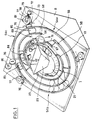
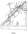
- the payment apparatus comprises a separator 1 in turn comprising a disc 2 which, in the service position shown in Figures 1 to 3, is in a plane P ( Figure 3) forming an angle A of approximately 45 ° with the vertical direction.
- the disc 2 has on its periphery cells 3 which open through an upper face 4 of the disc 2 and through its peripheral edge 6, opposite a lateral guide wall 7 which is integral with a frame 8 of the device.
- the bottom of the cells 3 is closed by a support face 9 for the coins or tokens, constituted by the upper face of a bottom plate 11 (FIG. 3).
- the disc 2 is connected in rotation to the output shaft 12 of an electric motor 13, the casing 14 of which is fixed to the underside of the plate 11.
- the plate 11 belongs to a frame 16 which is connected to the frame 8 of the apparatus by a hinge 17 which is adjacent to an upper region of the disc.
- the axis 18 of the articulation 17 is substantially horizontal and parallel to the plane P.
- the frame 16 is locked by a locking device 19 diametrically opposite the articulation 17, and which secures the frame 16 with the frame 8 of the device.
- the separator 1 further comprises a cover 21 traversed by the outlet orifice 22 of a hopper 23 into which the users throw coins, tokens or the like.
- the cover 21 is connected to the frame 8 of the device by a hinge 24 which is close to the hinge 17 and the upper region of the disc to allow the cover 21 and the hopper 23 to be raised when it is necessary to access disc 2, especially for maintenance.
- the coins 26 (figure 1) which are thrown into the hopper 23 meet a central conical reinforcement 27 (figures 2 and 3) of the disc 2 then move towards the lower region 28 of the disc 2, being prevented from falling lower by the cover 21.
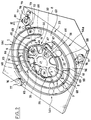
- Some parts are housed in the cells 3 which are in the lower region 28 of the disc and these parts are driven upwards in the direction of the arrow F in FIG. 2 by the rotation of the disc 2. This rotation also brings in the lower position new cells in which other parts are housed and so on until all the parts corresponding to the payment made are driven upwards by the cells 3 in the direction of the arrow F .
- the pieces pass through a splitting station 29 (FIG. 2) then into the field of action of a detector 31 which is only shown in dashed lines in FIG. 2 and which is for example of the type described in EP-A-0 420 921, in which case it is placed above the path of the coins or tokens and eccentrically with respect to this path, then finally by a station 32 for distributing the coins or tokens to destination of a display 33 which will be described in detail below.
- the splitting station 29 comprises (FIGS. 5, 6, 7) a notch 34 which is formed in the face inner peripheral and in the upper face of the lateral guide wall 7.
- the notch 34 is therefore open towards the disc 2 of which only the upper face 4 is represented by a dashed line in FIGS. 5 and 6.
- the notch 34 has a substantially flat inclined bottom 36.
- the low region 37 of the bottom 34 is located higher than the carrier face 9 of the carrier surface 11 and lower than the upper face 4 of the disc 2.
- the upper region 38 is further from the carrier face 9 than the lower region 37. In the example shown, the upper region 38 is even much further from the carrier face 9 than the upper face 4 of the disc.
- the lower region 37 of the notch widens radially and then the upper region 38 shrinks radially.
- the notch 34 is located opposite an ascending region of the path of the cells, and more particularly in the first half of the upward path of the cells, so that the carrier face 9 and the upper face of the disc lean towards the lateral guide wall 7 where the notch 34 is located.
- a discharge blade 39 is fixed to the cover 21 (see FIG. 2 and also FIGS. 14 and 15) so as to be in contact or almost in contact with the upper face 4 of the disc 2 at a location which is located after the notch 34 relative to the direction of travel of the cells, symbolized by the arrow F.
- the relative situation of the notch 34 and the delivery blade 39 is visible in FIG. 2 and in FIG. 13.
- the delivery blade 39 is intended to prevent the passage of objects which would significantly protrude relative to the upper face 4 of the disc 2.
- the discharge blade 39 is made elastic to avoid mechanical impact with said objects.
- the main purpose of this station is to prevent two causes of malfunction: the presence of two superimposed parts in the same cell 3 of the disc 2 ( Figure 8); and the presence of a part 41 or other object resting on the upper face 4 of the disc 2 as shown in FIG. 13.
- the distance between the delivery blade 39 and the carrying face 9 must be sufficient to allow the passage of the thickest parts under the blade 39.
- the distance between the blade 39 and the upper face 4 of the disc 2 must be small enough to prevent the passage of the thinnest parts likely to be received by the device.
- the disc 2 must have a certain minimum thickness that cannot be reduced and this minimum thickness allows two thin pieces to be entrained in superposition in the same cell 3 (FIG. 8).
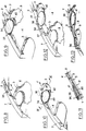
- the part 41 above which will be called below "the superimposed part” deviates radially outward from the other in entering the notch 34 ( Figure 9).
- the superimposed part 41 is subjected, in the example, to the cumulative effect of the centrifugal force, due to the rotation of the disc 2, and of gravity because the carrier face 9 leans towards the notch 34.
- the lower region 37 of the bottom of the notch 34 is close enough to the carrying face 9 to allow the radial sliding of the superimposed part 41 even if the underlying part 42 is particularly thin. However, since the lower region 37 is nevertheless at a certain distance from the support surface 9, the underlying part 42 cannot penetrate into the notch 34.
- the superimposed part 41 traverses the bottom of the notch 34 and thus reaches the upper region 38 of this bottom, which takes it off from the underlying part 42 and raises it until the point 43 of the superimposed part 41 on which the edge of the cell 3 rests to push the part 41 in the direction F, passes above the upper surface 4 of the disc ( Figures 10 and 11). Therefore, the superimposed part 41 escapes from the cell 3 ( Figure 12). As this happens in an ascending region of the path of the cells, the superimposed part 41 tends to go back relative to the disc and go to be housed in the next cell if it is free.
- Blade 39 has a shape of deflector which deflects the part 41 towards the center of the disc, as a result of which the part 41 can fall towards the lower region of the disc and occupy a new cell.
- the detector 31 recognizes the coin, or on the contrary detects that the coin or other token which has been introduced does not correspond to any known type, unless it gives an answer of doubt, a situation which will be studied later.
- the detector 31 is placed above the end of the upward path of the cells.
- the distribution station 32 which follows is mainly placed in the first half of the path down from the cells.
- the distribution station 32 (FIG. 2) includes a passage opening 43 for the parts which, according to the result of the detection operated by the detector 31, are considered to be good, and, after the opening 43 relative to the direction of rotation F of the disc 2, a passage opening 44 for the parts which have been recognized as not valid by the detector 31.
- the openings 43 and 44 are made through the lateral guide wall 7 opposite a recess 46 or respectively 47 formed in the carrying face 9. Each recess 46 or 47 communicates with the passage opening 43 or 44 associated by a respective tunnel 48 (FIG. 4) formed in the plate 11.
- a hatch 49 fixed to the plunger core of an electro- magnet 51 for actuating this flap is movable so as to be able to assume a release position (FIGS.
- the tunnel 48 has an oblique orientation relative to the local radial direction so that the path of the parts from the recess 46 to the display is generally descending thanks to the inclination of the plane P.
- the flap 49 closes the recess 46 so that the upper face 53 of the flap 49 completes without significant discontinuity the carrying face 9 of the plate 11.
- the electromagnet 51 is controlled to place the hatch 49 in the closed position for the passage of a cell 3 of the disc 2 when the detection operated by the detector 31 has revealed that the part 52 is not of a model accepted by the device or that Exhibit 52 has not been identified with certainty.
- a part such as 52 continues its path along the lateral guide wall 7 until it meets the second recess 47, which is equipped, in the same way as the first recess with a hatch 50 ( in the closed position in Figure 2) controlled by an electromagnet.
- this second hatch 50 is open and the room falls there to leave towards the display 33 through the passage opening 44 after having passed through a tunnel similar to the tunnel 48 of FIG. 4. If the room is doubtful, the hatch 50 of the second recess 47 is closed and the part is again driven by the disc 2 towards the detection means.
- the step 94 "detection” includes detection by the detector 31.
- the test 96 checks whether the display 33 is ready or if, on the contrary, it is moving. In the second case, the part is returned to detection (step 94), that is to say that the two doors 49, 50 are kept closed. If the display unit 33 is ready, the result of the detection is subjected to a test 97. If the part is recognized as acceptable, the flap 49 opens and the part can pass through the opening 43 towards the display 33. Otherwise, the result of the detection is subjected to a second test "part refused ? " 98.
- the hatch 49 is kept closed and the hatch 50 is open to allow the piece to exit through the opening 44 towards the display 33. If the piece is not not recognized with certainty as a different part from the accepted parts, we carry out a test "first pass?" 99. During this test, it is checked whether a questionable part, that is to say neither accepted nor refused, has already passed into the field of action of the detector 31 by occupying the same cell 3 of the disk 2. This is achievable by knowing the number of cells in the disc and counting the cyclic disturbances created by the passage of cells in the detector field.
- step 101 If the answer is no, in other words if the questionable coin has just made its first pass in the detector field, its position in the cycle is memorized (step 101), and it is returned to the detector's field of action (step 94) to give it a new chance of identification. It is precisely the memorization step 101 which then makes it possible to count the cell passages under the detector 31 until the second passage of the room. If the piece is positively accepted or refused on the second pass, this memorization is then erased. If, on the second pass, the part is again dubious, it is sent to the passage opening 44 ("NO" output in test 99).
- the display 33 is an annular display surrounding the separator 1 and it comprises three presentation regions 54a, 54b and 54c distributed angularly around the axis of the disc 2 (FIG. 2).
- Each presentation region 54a, 54b, 54c includes two compartments 56 and 57 for the accepted coins and respectively for the rejected coins.
- the compartments have shapes in a circle sector.
- a central rib 58 of generally circular shape, separates the compartments 56 located radially outside and the compartments 57 located radially inside.
- Two other ribs of generally circular shape 59 and 61 limit the compartments radially outwards, and respectively radially inward the compartments 57.
- the ribs 58, 59 and 61 are integral with the frame 8 of the device, likewise a plate 62 on which the parts rest and can slide.
- the inner peripheral ribs 61 and central 58 have for the passage of the accepted parts two passages 63 and 64 aligned opposite the opening 43 along the desired oblique path relative to the local radial direction from the recess 46 to the radially outer compartments 57 intended for accepted parts.
- the radially inner rib 61 has, after passage 63 relative to the direction of travel F of the cells, a second passage 64 opposite the passage opening 44 for the passage of the parts from the recess 47 in the radially compartments 57 interiors intended for rejected parts.
- the presentation regions 54a, 54b and 54c are separated by partitions.
- partitions There are in particular three external partitions 68 which separate the radially external compartments 56 from one another and extend between the central rib 58 and the external peripheral rib 59.
- the partitions also comprise three internal partitions 69 which separate one from the other, the radially inner compartments 57 and extend between the central rib 58 and the inner peripheral rib 61.
- the partitions 69 are of relatively great circumferential length and are each crossed by a passage 71.
- the partitions 68 and 69 are fixed to the underside of a transparent cover 72 which is of annular shape and of which, for reasons of clarity, only a portion of the radially outer edge has been shown (by small crosses).
- 73 situated radially beyond the outer peripheral rib 59, and a part of the radially inner edge 74 which is roughly adjacent to the inner peripheral rib 61.
- the cover 72 rests on three support rollers 76 with a radial axis, supported in rotation by the frame 8, and it is centered between three centering rollers 77 resting on the outer peripheral edge 73 of the cover 72.
- the three load-bearing rollers 76 are free to rotate, as are two of the centering rollers 77, which are supported by the frame 8 of the device.
- the third centering roller 77 (top right of FIG. 2) is supported in rotation by a yoke 78 which is pushed by a spring 79 so that the roller 77 tends to bear elastically both against the peripheral edge 73 of the cover 72 and against the output shaft 81 of an electric motor 82 (FIG. 4) for rotating the cover 72 around the axis of the disc.
- the motor 82 is excited to rotate the cover 72 by a third of a turn in the direction of the arrow F each time a payment has been made.
- the cover 72 is stopped, as shown in FIG. 2, there is a partition 68 which is located just before the passage 64 provided in the central rib 58, and a partition 69 which is stopped just before the passage 67 through the inner peripheral rib 61, while the passage 71 of the same partition 69 extends obliquely downward, relative to the local radial direction, from the passage 63 through the inner peripheral rib to the passage 64 through the central rib 58.
- the presentation region (54a in FIG. 2) which is limited at the rear by the two partitions 68 and 69 located in the position which we have just spoken of, that is to say just before passage 64 and respectively the passage 67 is in a position known as receiving the parts. Indeed, if a part is authorized to leave the separator through the passage opening 43, it will reach by gravity the radially outer compartment 56 of the region 54a after having crossed the passage 63, the corridor 71 and the passage 64. In addition, a part authorized to leave the separator through the opening 44 as described above reaches the radially inner compartment 57 after having crossed the passage 67.
- another presentation region, 54b is in the presentation position, in which one can observe the coins contained in the two compartments 56 and 57 of this region, coins which correspond to the previous payment.
- the third presentation region 54c is in the transmission position: the partitions 68 and 69 which delimit the rear of this region (top left of FIG. 2) have pushed the pieces corresponding to an even previous payment.
- orifices 83 and 84 respectively leading to a collection chest and to a means for returning the pieces refused to the user.
- the orifice 83 can be closed, for example if the corresponding trunk is full, in which case the parts will be evacuated through a second orifice 86 leading for example to another trunk.
- the motor 82 is controlled to rotate the cover 72 by a third of a turn, so that the presentation region which was in the reception position changes to the presentation position, that which was in the presentation position changes to the transmission position and the one that was in the transmission position returns to the receiving position. It is during this last movement that the parts pass through the orifice 86 if the orifice 83 was closed.
- each presentation region are, at least during the upward phase of the journey, pushed by the partitions 68 and 69 located at the rear of the compartment, the downward phase being effected by gravity .
- the plate 62 extends in a plane Q parallel to the plane P of the disc 2, although slightly lowered relative to the latter, by a distance h, (see in particular FIG. 3) for that the parts which have fallen into the recess 46 or the recess 47 can then slide on the plate 62 without encountering any obstacle.
- the locking device 19 (FIG. 3) comprises an electromagnet 87 for unlocking control, capable of retracting a lock 88 of the locking device 19 against a return spring 89.
- the lock 88 When the lock 88 is retracted, the mount 16 and with it the motor 13 and the disc 2 can pivot down around the articulation 17 to the position shown in FIG. 17, called the purge position, in which the disc 2 s 'is spaced from the cover 21, the detector 31, the lateral guide wall 7 and the discharge blade 39.
- the disc 2 is then in a plane P 1 forming with the vertical direction an angle B less than the angle A in Figure 3. This position is defined by support of the mount 16 against a stop 91.
- the fall of foreign bodies likely to be on the disc 2 is favored, in particular if these bodies were initially held captive by friction between the disc 2 and for example the cover 21 , the discharge blade 39 secured to the cover 21 or the detector 31 fixed to the frame 8 of the device.
- the motor 13 it is possible to cause the motor 13 to rotate in alternating directions or in only one direction. This is possible because the pivoting of the mount 16 towards the purge position in no way affects the coupling between the motor 13 and the disc 2.
- An actuator 92 for example an electromagnet, is provided to bring the mount 16 back into the service position. This actuator 92 can also be used to shake the frame 16 and further promote the fall of foreign bodies.
- a so-called “conical” disc can be used, the cells of which are arranged in a truncated cone having an axis which may be vertical. There is thus at all points of the periphery a slope by which the parts tend to move radially outward from the disc.
- the annular display itself has, advantageously a frustoconical shape.
- the hatches 49 and 50 can be replaced by pivoting flaps, or even by gates formed in the lateral guide wall.
Abstract
Description
La présente invention concerne un procédé de reconnaissance d'objets du type pièces de monnaie.The present invention relates to a method of recognizing objects of the coin type.
On connaît d'après le EP-A-0 420 921 un appareil de paiement automatique dans lequel un disque séparateur reçoit sur sa face supérieure les pièces ou jetons à séparer et comporte à sa périphérie des alvéoles destinées à recevoir chacune une pièce ou jeton. A cet effet, les alvéoles s'ouvrent à travers la face supérieure du disque. Elles s'ouvrent également en regard d'une paroi périphérique fixe formant paroi latérale de guidage pour les pièces ou jetons entraînés en rotation par les alvéoles. Le long de ce trajet, les pièces glissent sur une surface porteuse fixe. Elles passent dans le champ d'action d'un détecteur. Elles atteignent ensuite une ouverture de passage vers un présentoir circulaire situé à côté du disque rotatif. En fonction du résultat de la détection opérée par le détecteur, l'ouverture de passage est configurée selon l'une ou l'autre de deux configuration différentes conduisant les pièces ou jetons soit vers un compartiment périphérique du présentoir soit vers un compartiment central. Il y a trois compartiments centraux et trois compartiment périphériques. Lorsqu'une région de présentation comprenant un compartiment central et un compartiment périphérique est en position de recevoir les pièces ou jetons en provenance du disque séparateur à travers l'ouverture de passage, une autre région de présentation comprenant un autre compartiment périphérique et un autre compartiment central est dans une position de présentation, dans laquelle les pièces ou jetons correspondant à un précédent paiement sont visibles par les usagers, tandis qu'une troisième région de présentation, comprenant le troisième compartiment périphérique et le troisième compartiment central, se trouve dans une position de transmission des pièces ou jetons vers un poste ultérieur, par exemple un coffre de stockage des pièces ou jetons, un dispositif de restitution pour les pièces ou jetons non acceptés, etc.EP-A-0 420 921 discloses an automatic payment device in which a separating disc receives on its upper face the coins or tokens to be separated and comprises at its periphery cells intended to each receive a coin or token. For this purpose, the cells open through the upper face of the disc. They also open opposite a fixed peripheral wall forming a lateral guide wall for the coins or tokens driven in rotation by the cells. Along this path, the pieces slide on a fixed supporting surface. They pass within the field of action of a detector. They then reach a passage opening towards a circular display located next to the rotating disc. Depending on the result of the detection operated by the detector, the passage opening is configured according to one or the other of two different configurations leading the coins or tokens either to a peripheral compartment of the display or to a central compartment. There are three central compartments and three peripheral compartments. When a presentation region comprising a central compartment and a peripheral compartment is in a position to receive the coins or tokens coming from the separating disc through the passage opening, another presentation region comprising another peripheral compartment and another compartment central is in a display position, in which the coins or tokens corresponding to a previous payment are visible by the users, while a third presentation region, comprising the third peripheral compartment and the third central compartment, is in a position for transmitting the coins or tokens to a subsequent station, for example a chest for storing the coins or tokens, a return device for coins or tokens not accepted, etc.
Sur le disque, une barrette de refoulement est destinée à empêcher les pièces superposées de parvenir jusqu'au détecteur. Mais comme la barrette de refoulement doit être placée à une distance suffisante de la surface porteuse pour permettre le passage des pièces les plus épaisses, cette barrette est dans certains cas incapable d'empêcher le passage simultané de deux pièces minces qui se seraient logées dans la même alvéole. De toute façon, si la deuxième pièce dépasse de la surface supérieure du disque, il est dangereux de tenter de la déloger par la barrette de refoulement car cela risque d'entraîner un blocage et des dégâts. On ne peut pas résoudre ce problème en amincissant le disque car cela permettrait à une pièce mince de passer entre la surface supérieure du disque et la barrette de refoulement.On the disc, a delivery bar is intended to prevent the superimposed parts from reaching the detector. But as the delivery bar must be placed at a sufficient distance from the bearing surface to allow the passage of the thickest parts, this bar is in some cases incapable of preventing the simultaneous passage of two thin parts which would have lodged in the same cell. In any case, if the second part protrudes from the upper surface of the disc, it is dangerous to try to dislodge it by the delivery bar as this may cause blockage and damage. This problem cannot be solved by thinning the disc as this would allow a thin piece to pass between the upper surface of the disc and the delivery bar.
D'autres perturbations dans la rotation du disque peuvent se produire, notamment si des corps étrangers ont pénétré dans la chambre où tourne le disque. Ces corps étrangers peuvent se loger entre le disque et la barrette de refoulement, ou sous le détecteur, entre le disque et la paroi de fond, ou encore dans les pièces mobiles définissant la configuration de l'ouverture de passage. En cas d'un tel incident, le nettoyage de l'appareil connu peut prendre un certain temps et par conséquent entraîner un dérangement préjudiciable au bon fonctionnement de tout le poste de péage.Other disturbances in the rotation of the disc can occur, especially if foreign bodies have entered the chamber where the disc spins. These foreign bodies can be housed between the disc and the delivery bar, or under the detector, between the disc and the bottom wall, or even in the moving parts defining the configuration of the passage opening. In the event of such an incident, cleaning the known device may take some time and therefore result in a disturbance detrimental to the proper functioning of the entire toll booth.
Il peut arriver que certaines pièces soient douteuses, c'est-à-dire que la réponse du détecteur au passage de la pièce ne diffère que très peu de la réponse correspondant à une pièce valide. Une telle pièce pourra être refusée par l'appareil. Ceci entraîne une perturbation d'exploitation inutile si en réalité il s'agit par exemple d'une pièce très usée mais tout de même valable.It may happen that certain parts are doubtful, that is to say that the response of the detector to the passage of the part differs only very little from the response corresponding to a valid part. Such a part may be refused by the device. This leads to an unnecessary operating disruption if in reality it is for example a very worn part but still valid.
Enfin, dans l'appareil connu, le dispositif de présentation est assez encombrant puisque son diamètre est supérieur à celui du dispositif de séparation et il fait donc plus que doubler la surface nécessaire pour loger côte à côte les deux dispositifs, par rapport à celle qu'exigerait le dispositif de séparation seul.Finally, in the known apparatus, the presentation device is quite bulky since its diameter is greater than that of the separation device and it therefore more than doubles the surface necessary to accommodate the two devices side by side, compared to that which 'would require the separation device alone.
Le but de la présente invention est de remédier à ces inconvénients.The object of the present invention is to remedy these drawbacks.
Selon l'invention, il est prévu un procédé de reconnaissance d'objets du genre pièces de monnaie, dans lequel on fait passer les objets un à un dans le champ d'action d'un détecteur appartenant à un dispositif de reconnaissance, et en fonction de la réponse du détecteur au passage de chaque objet, on dirige sélectivement l'objet vers au moins une sortie du dispositif de reconnaissance et respectivement on renvoie l'objet dans le champ d'action du détecteur.According to the invention, a method of recognizing objects of the coin type is provided, in which the objects are passed one by one within the field of action of a detector belonging to a recognition device, and in depending on the detector's response to the passage of each object, the object is selectively directed to at least one output of the recognition device and respectively the object is returned to the detector's field of action.
D'autres particularités et avantages de l'invention ressortiront encore de la description ci-après relatifs à des exemples non limitatifs.Other features and advantages of the invention will emerge from the description below relating to nonlimiting examples.
Aux dessins annexés :
- la figure 1 est une vue schématique en perspective d'un appareil de paiement automatique mettant en oeuvre le procédé selon l'invention ;
- la figure 2 est une vue analogue à la figure 1 lorsque le capot du séparateur est enlevé ;
- la figure 3 est une vue schématique de l'appareil en coupe axiale ;
- la figure 4 est une vue en coupe selon la ligne IV-IV de la figure 2, avec représentation du capot du séparateur, lors du passage d'une pièce depuis le séparateur vers le présentoir ;
- la figure 5 est une vue en perspective d'une partie de la paroi porteuse et de la paroi de guidage latéral du séparateur ;
- la figure 6 est une vue en élévation de cette partie de la paroi de guidage latéral, avec coupe de la paroi porteuse ;
- la figure 7 est une vue en plan de la même partie de la paroi de guidage latéral ;
- les figures 8, 9, 10 et 12 représentent quatre stades successifs du processus d'éjection d'une pièce superposée ;
- la figure 11 est une vue en coupe selon le plan XI-XI de la figure 10 ;
- la figure 13 est une vue en perspective montrant la lame de refoulement en train d'empêcher une pièce de progresser vers le détecteur sans s'être logée dans une alvéole ;
- les figures 14 et 15 sont deux vues en perspective montrant respectivement la face intérieure et la face extérieure du capot ;
- la figure 16 est une vue d'un détail de la figure 4 dans le cas d'une pièce non admise, donc empêchée de passer du séparateur vers un compartiment extérieur du présentoir ;
- la figure 17 est une vue analogue à la figure 3 mais lorsque la monture est en position de purge ; et
- la figure 18 est un organigramme d'aiguillage des pièces.
- Figure 1 is a schematic perspective view of an automatic payment device implementing the method according to the invention;
- Figure 2 is a view similar to Figure 1 when the separator cover is removed;
- Figure 3 is a schematic view of the apparatus in axial section;
- Figure 4 is a sectional view along the line IV-IV of Figure 2, with representation of the separator cover, during the passage of a part from the separator to the display;
- Figure 5 is a perspective view of part of the carrier wall and the lateral guide wall of the separator;
- Figure 6 is an elevational view of this part of the lateral guide wall, with section of the carrier wall;
- FIG. 7 is a plan view of the same part of the lateral guide wall;
- Figures 8, 9, 10 and 12 show four successive stages in the process of ejecting a stacked part;
- Figure 11 is a sectional view along the plane XI-XI of Figure 10;
- FIG. 13 is a perspective view showing the delivery blade preventing a part from advancing towards the detector without being housed in a cell;
- Figures 14 and 15 are two perspective views respectively showing the inner face and the outer face of the cover;
- Figure 16 is a view of a detail of Figure 4 in the case of a part not admitted, therefore prevented from pass from the separator to an external compartment of the display;
- Figure 17 is a view similar to Figure 3 but when the frame is in the purge position; and
- Figure 18 is a flow diagram of parts switching.
Comme le montrent les figures 1 à 3, l'appareil de paiement comprend un séparateur 1 comprenant à son tour un disque 2 qui, dans la position de service représentée aux figures 1 à 3, se trouve dans un plan P (figure 3) formant un angle A d'environ 45° avec la direction verticale. Le disque 2 comporte sur son pourtour des alvéoles 3 qui s'ouvrent à travers une face supérieure 4 du disque 2 et à travers son bord périphérique 6, en regard d'une paroi de guidage latéral 7 qui est solidaire d'un bâti 8 de l'appareil. Le fond des alvéoles 3 est fermé par une face porteuse 9 pour les pièces ou jetons, constituée par la face supérieure d'une plaque de fond 11 (figure 3). Le disque 2 est relié en rotation à l'arbre de sortie 12 d'un moteur électrique 13 dont le carter 14 est fixé à la face inférieure de la plaque 11. La plaque 11 appartient à une monture 16 qui est reliée au bâti 8 de l'appareil par une articulation 17 qui est adjacente à une région haute du disque. L'axe 18 de l'articulation 17 est sensiblement horizontal et parallèle au plan P. Dans la position de service représentée, la monture 16 est verrouillée par un dispositif de verrouillage 19 diamétralement opposé à l'articulation 17, et qui solidarise la monture 16 avec le bâti 8 de l'appareil.As shown in Figures 1 to 3, the payment apparatus comprises a
Le séparateur 1 comprend en outre un capot 21 traversé par l'orifice de sortie 22 d'une trémie 23 dans laquelle les usagers jettent des pièces de monnaie, jetons ou analogues. Le capot 21 est relié au bâti 8 de l'appareil par une articulation 24 qui est voisine de l'articulation 17 et de la région haute du disque pour permettre de soulever le capot 21 et la trémie 23 lorsqu'il est nécessaire d'accéder au disque 2, notamment pour l'entretien.The
Les pièces de monnaie 26 (figure 1) qui sont jetées dans la trémie 23 rencontrent un renfort conique central 27 (figures 2 et 3) du disque 2 puis se dirigent vers la région inférieure 28 du disque 2, en étant empêchées de tomber plus bas par le capot 21. Certaines pièces se logent dans les alvéoles 3 qui sont dans la région basse 28 du disque et ces pièces sont entraînées vers le haut dans le sens de la flèche F à la figure 2 par la rotation du disque 2. Cette rotation amène également en position basse de nouvelles alvéoles dans lesquelles se logent d'autres pièces et ainsi de suite jusqu'à ce que l'ensemble des pièces correspondant au paiement effectué soit entraîné vers le haut par les alvéoles 3 dans le sens de la flèche F.The coins 26 (figure 1) which are thrown into the
Au cours de ce mouvement, les pièces passent par un poste de dédoublement 29 (figure 2) puis dans le champ d'action d'un détecteur 31 qui n'est représenté qu'en traits mixtes à la figure 2 et qui est par exemple du type décrit dans le EP-A-0 420 921, auquel cas il est placé au-dessus du trajet des pièces ou jetons et de manière excentrée par rapport à ce trajet, puis enfin par un poste 32 de distribution des pièces ou jetons à destination d'un présentoir 33 qui sera décrit en détail plus loin.During this movement, the pieces pass through a splitting station 29 (FIG. 2) then into the field of action of a
Le poste de dédoublement 29 comprend (figures 5, 6, 7) une encoche 34 qui est pratiquée dans la face périphérique intérieure et dans la face supérieure de la paroi de guidage latéral 7. L'encoche 34 est donc ouverte vers le disque 2 dont seule la face supérieure 4 est représentée par un trait mixte aux figures 5 et 6.The splitting
L'encoche 34 comporte un fond incliné 36 sensiblement plan. Lorsqu'on parcourt le fond 36 dans le sens de la rotation du disque (flèche F), on part d'une région basse 37 du fond pour arriver à une région haute 38. La région basse 37 du fond 34 est située plus haut que la face porteuse 9 de la surface porteuse 11 et plus bas que la face supérieure 4 du disque 2. La région haute 38 est plus éloignée de la face porteuse 9 que la région basse 37. Dans l'exemple représenté, la région haute 38 est même nettement plus éloignée de la face porteuse 9 que la face supérieure 4 du disque.The
De plus, lorsque l'on parcourt l'encoche dans le sens F de défilement des alvéoles, la région basse 37 de l'encoche s'élargit radialement puis la région haute 38 se rétrécit radialement.In addition, when the notch is traversed in the direction F of movement of the cells, the
Il importe encore de noter que l'encoche 34 se trouve en regard d'une région ascendante du trajet des alvéoles, et plus particulièrement dans la première moitié du trajet ascendant des alvéoles, de sorte que la face porteuse 9 et la face supérieure du disque penchent vers la paroi de guidage latéral 7 à l'endroit où se trouve l'encoche 34.It is also important to note that the
Une lame de refoulement 39 est fixée au capot 21 (voir figure 2 et aussi figures 14 et 15) de manière à se trouver en contact ou quasi-contact avec la face supérieure 4 du disque 2 en un emplacement qui est situé après l'encoche 34 relativement au sens de défilement des alvéoles, symbolisée par la flèche F. La situation relative de l'encoche 34 et de la lame de refoulement 39 est visible à la figure 2 et à la figure 13. La lame de refoulement 39 est destinée à empêcher le passage d'objets qui feraient significativement saillie par rapport à la face supérieure 4 du disque 2. Toutefois, la lame de refoulement 39 est réalisée élastique pour éviter les chocs mécaniques avec lesdits objets.A
On va maintenant décrire, en référence aux figures 8 à 13, le fonctionnement du poste de dédoublement.We will now describe, with reference to Figures 8 to 13, the operation of the splitting station.
Ce poste a essentiellement pour but d'empêcher deux causes de malfonctionnement : la présence de deux pièces superposées dans la même alvéole 3 du disque 2 (figure 8) ; et la présence d'une pièce 41 ou autre objet reposant sur la face supérieure 4 du disque 2 comme cela est représenté à la figure 13. La distance entre la lame de refoulement 39 et la face porteuse 9 doit être suffisante pour permettre le passage des pièces les plus épaisses sous la lame 39. De plus, la distance entre la lame 39 et la face supérieure 4 du disque 2 doit être suffisamment faible pour empêcher le passage des pièces les plus minces susceptibles d'être reçues par l'appareil. Il en résulte que le disque 2 doit avoir une certaine épaisseur minimale impossible à réduire et cette épaisseur minimale permet à deux pièces minces d'être entraînées en superposition dans la même alvéole 3 (figure 8).The main purpose of this station is to prevent two causes of malfunction: the presence of two superimposed parts in the
Quand deux pièces ainsi superposées arrivent en regard de l'encoche 34, la pièce 41 du dessus, qu'on appellera ci-après "la pièce superposée" s'écarte radialement vers l'extérieur par rapport à l'autre en pénétrant dans l'encoche 34 (figure 9). Ceci résulte du fait que la pièce superposée 41 est soumise, dans l'exemple, à l'effet cumulé de la force centrifuge, en raison de la rotation du disque 2, et de la gravité car la face porteuse 9 penche vers l'encoche 34. La région basse 37 du fond de l'encoche 34 est suffisamment proche de la face porteuse 9 pour permettre le glissement radial de la pièce superposée 41 même si la pièce sous-jacente 42 est particulièrement mince. Mais comme la région basse 37 est tout de même à une certaine distance de la surface porteuse 9, la pièce sous-jacente 42 ne peut pas pénétrer dans l'encoche 34.When two pieces thus superimposed arrive opposite the
Comme les deux pièces 41 et 42 continuent d'être entraînées par le disque 2, la pièce superposée 41 parcourt le fond de l'encoche 34 et atteint ainsi la région haute 38 de ce fond, ce qui la décolle de la pièce sous-jacente 42 et la soulève jusqu'à ce que le point 43 de la pièce superposée 41 sur lequel s'appuyait le bord de l'alvéole 3 pour pousser la pièce 41 dans le sens F, passe au-dessus de la surface supérieure 4 du disque (figures 10 et 11). Dès lors, la pièce superposée 41 s'échappe de l'alvéole 3 (figure 12). Comme cela se passe en une région ascendante du trajet des alvéoles, la pièce superposée 41 tend à revenir en arrière relativement au disque et aller se loger dans l'alvéole suivante si elle est libre.As the two
Mais on peut craindre qu'il s'établisse entre la pièce superposée 41 et la surface supérieure 4 du disque un contact d'adhérence qui entraîne la pièce 41 dans le champ du détecteur 31 (figure 2) avant qu'elle n'ait le temps de se loger dans une alvéole 3 suivante. La lame de refoulement 39 (figure 13) évite ce risque et stoppe la pièce 41 avant qu'elle n'atteigne le détecteur. La lame 39 a une forme de déflecteur qui dévie la pièce 41 vers le centre du disque, à la suite de quoi la pièce 41 peut tomber vers la région inférieure du disque et occuper une nouvelle alvéole.However, it is feared that there will be established between the
Le détecteur 31 reconnaît la pièce, ou au contraire détecte que la pièce ou autre jeton qui a été introduit ne correspond à aucun type connu, à moins qu'il ne donne une réponse de doute, situation qui sera étudiée plus loin. Le détecteur 31 est placé au-dessus de la fin du trajet ascendant des alvéoles. Le poste de distribution 32, qui suit, est placé pour l'essentiel dans la première moitié du trajet descendant des alvéoles.The
Le poste de distribution 32 (figure 2) comprend une ouverture de passage 43 pour les pièces qui, en fonction du résultat de la détection opérée par le détecteur 31, sont considérées comme bonnes, et, après l'ouverture 43 relativement au sens de rotation F du disque 2, une ouverture de passage 44 pour les pièces qui ont été reconnues comme non valables par le détecteur 31. Les ouvertures 43 et 44 sont pratiquées à travers la paroi de guidage latéral 7 en regard d'un évidement 46 ou respectivement 47 pratiqué dans la face porteuse 9. Chaque évidement 46 ou 47 communique avec l'ouverture de passage 43 ou 44 associée par un tunnel 48 respectif (figure 4) pratiqué dans la plaque 11. Une trappe 49 fixée au noyau plongeur d'un électro-aimant 51 d'actionnement de cette trappe est mobile pour pouvoir prendre une position de dégagement (figures 2 et 4) dans laquelle la trappe est rétractée vers le bas pour dégager l'évidement 46 et permettre ainsi aux pièces de monnaie 52 contenues dans les alvéoles de tomber dans l'évidement 46 puis de là passer par gravité à travers le tunnel 48 et l'ouverture de passage 43 en direction du présentoir 33. Pour permettre ce mouvement par gravité, le tunnel 48 a une orientation oblique par rapport à la direction radiale locale de manière que le trajet des pièces depuis l'évidement 46 jusqu'au présentoir soit globalement descendant grâce à l'inclinaison du plan P.The distribution station 32 (FIG. 2) includes a
Dans une autre position, ou position de fermeture (figure 16) la trappe 49 ferme l'évidement 46 de manière que la face supérieure 53 de la trappe 49 complète sans discontinuité significative la face porteuse 9 de la plaque 11. L'électro-aimant 51 est piloté pour placer la trappe 49 dans la position de fermeture au passage d'une alvéole 3 du disque 2 lorsque la détection opérée par le détecteur 31 a révélé que la pièce 52 n'est pas d'un modèle admis par l'appareil ou que la pièce 52 n'a pas été identifiée avec certitude. Dans ce cas, une pièce telle que 52 continue son trajet le long de la paroi de guidage latéral 7 jusqu'à ce qu'elle rencontre le deuxième évidement 47, qui est équipé, de manière identique au premier évidement d'une trappe 50 (en position de fermeture à la figure 2) commandée par un électro-aimant. Si la pièce est reconnue comme non admise, cette deuxième trappe 50 est ouverte et la pièce y tombe pour partir vers le présentoir 33 par l'ouverture de passage 44 après avoir traversé un tunnel semblable au tunnel 48 de la figure 4. Si la pièce est douteuse, la trappe 50 du deuxième évidement 47 est fermée et la pièce est de nouveau entraînée par le disque 2 vers les moyens de détection.In another position, or closed position (FIG. 16), the
Une pièce qui se présente en regard des ouvertures de passage 43 ou 44 lors de la rotation du présentoir 33, rotation qui sera explicitée plus loin, est également renvoyée dans le champ d'action du détecteur, pour éviter que la pièce aille interférer avec la rotation du présentoir.A part which is presented opposite the
Ce procédé est explicité par l'organigramme de la figure 18. L'étape 94 "détection" comprend la détection par le détecteur 31. Le test 96 vérifie si le présentoir 33 est prêt ou si au contraire il est en train de se déplacer. Dans le deuxième cas, la pièce est renvoyée à la détection (étape 94) c'est-à-dire que l'on maintient fermées les deux trappes 49, 50. Si le présentoir 33 est prêt, le résultat de la détection subit un test 97. Si la pièce est reconnue acceptable, la trappe 49 s'ouvre et la pièce peut passer par l'ouverture 43 vers le présentoir 33. Dans le cas contraire, le résultat de la détection est soumis à un deuxième test "pièce refusée ?" 98. Si la pièce est reconnue sans ambiguité comme différente des pièces acceptables, la trappe 49 est maintenue fermée et la trappe 50 est ouverte pour permettre à la pièce de sortir par l'ouverture 44 vers le présentoir 33. Si la pièce n'est pas reconnue avec certitude comme une pièce différente des pièces acceptées, on effectue un test "premier passage ?" 99. Au cours de ce test, on vérifie si une pièce douteuse c'est-à-dire ni acceptée ni refusée, est déjà passée dans le champ d'action du détecteur 31 en occupant la même alvéole 3 du disque 2. Ceci est réalisable en connaissant le nombre d'alvéoles du disque et en comptant les perturbations cycliques créées par le passage des alvéoles dans le champ du détecteur. Si la réponse est non, autrement dit si la pièce douteuse vient d'effectuer son premier passage dans le champ du détecteur, on mémorise sa position dans le cycle (étape 101), et on la renvoit dans le champ d'action du détecteur (étape 94) pour lui donner une nouvelle chance d'identification. C'est justement l'étape de mémorisation 101 qui permet ensuite de compter les passages d'alvéoles sous le détecteur 31 jusqu'au deuxième passage de la pièce. Si au deuxième passage la pièce est positivement acceptée ou refusée, cette mémorisation est ensuite effacée. Si au deuxième passage la pièce est de nouveau douteuse, elle est envoyée vers l'ouverture de passage 44 (sortie "NON" au test 99).This process is explained by the flowchart in FIG. 18. The
Le présentoir 33 est un présentoir annulaire entourant le séparateur 1 et il comprend trois régions de présentation 54a, 54b et 54c réparties angulairement autour de l'axe du disque 2 (figure 2).The
Chaque région de présentation 54a, 54b, 54c, comprend deux compartiments 56 et 57 pour les pièces acceptées et respectivement pour les pièces refusées. Les compartiment ont des formes en secteur de cercle. Une nervure centrale 58, de forme générale circulaire,sépare les compartiments 56 situés radialement à l'extérieur et les compartiments 57 situés radialement à l'intérieur. Deux autres nervures de forme générale circulaire 59 et 61 limitent radialement vers l'extérieur les compartiments 56, et respectivement radialement vers l'intérieur les compartiments 57. Les nervures 58, 59 et 61 sont solidaires du bâti 8 de l'appareil, de même qu'une platine 62 sur laquelle les pièces reposent et peuvent glisser.Each
Les nervures périphériques intérieure 61 et centrale 58 présentent pour le passage des pièces acceptées deux passages 63 et 64 alignés en regard de l'ouverture 43 selon le trajet oblique voulu par rapport à la direction radiale locale depuis l'évidement 46 vers les compartiments radialement extérieurs 57 destinés aux pièces acceptées.The inner
En outre, la nervure radialement intérieure 61 présente, après le passage 63 relativement au sens de défilement F des alvéoles, un deuxième passage 64 en regard de l'ouverture de passage 44 pour le passage des pièces depuis l'évidement 47 dans les compartiments radialement intérieurs 57 destinés aux pièces refusées.In addition, the radially
Les régions de présentation 54a, 54b et 54c sont séparées par des cloisonnements. Il y a en particulier trois cloisonnements extérieurs 68 qui séparent l'un de l'autre les compartiments radialement extérieurs 56 et s'étendent entre la nervure centrale 58 et la nervure périphérique extérieure 59. Les cloisonnements comprennent en outre trois cloisonnements intérieurs 69 qui séparent l'un de l'autre les compartiments radialement intérieurs 57 et s'étendent entre la nervure centrale 58 et la nervure périphérique intérieure 61. Les cloisonnements 69 sont de relativement grande longueur circonférentielle et sont traversés chacun par un couloir 71.The
Les cloisonnements 68 et 69 sont fixés à la face inférieure d'un couvercle transparent 72 qui est de forme annulaire et dont, pour des raisons de clarté, on n'a représenté (par des petites croix) qu'une partie du bord radialement extérieur 73 situé radialement au-delà de la nervure périphérique extérieure 59, et une partie du bord radialement intérieur 74 qui est à peu près adjacent à la nervure périphérique intérieure 61.The
Pour son positionnement, le couvercle 72 repose sur trois galets porteurs 76 à axe radial, supportés en rotation par le bâti 8, et il est centré entre trois galets de centrage 77 s'appuyant sur le bord périphérique extérieur 73 du couvercle 72. Les trois galets porteurs 76 sont libres en rotation, de même que deux des galets de centrage 77, lesquels sont supportés par le bâti 8 de l'appareil. Le troisième galet de centrage 77 (en haut à droite de la figure 2) est supporté en rotation par une chape 78 qui est poussée par un ressort 79 de manière que le galet 77 tende à s'appuyer élastiquement à la fois contre le bord périphérique 73 du couvercle 72 et contre l'arbre de sortie 81 d'un moteur électrique 82 (figure 4) d'entraînement en rotation du couvercle 72 autour de l'axe du disque.For its positioning, the
Par des moyens de pilotage non représentés, le moteur 82 est excité pour faire tourner le couvercle 72 d'un tiers de tour dans le sens de la flèche F à chaque fois qu'un paiement a été effectué. Lorsque le couvercle 72 est à l'arrêt, comme représenté à la figure 2, il y a un cloisonnement 68 qui est situé juste avant le passage 64 ménagé dans la nervure centrale 58, et un cloisonnement 69 qui est arrêté juste avant le passage 67 à travers la nervure périphérique intérieure 61, tandis que le couloir 71 du même cloisonnement 69 s'étend obliquement vers le bas, par rapport à la direction radiale locale, depuis le passage 63 à travers la nervure périphérique intérieure jusqu'au passage 64 à travers la nervure centrale 58.By means of control not shown, the
La région de présentation (54a à la figure 2) qui est limitée à l'arrière par les deux cloisonnements 68 et 69 se trouvant dans la position dont on vient de parler, c'est-à-dire juste avant le passage 64 et respectivement le passage 67, se trouve dans une position dite de réception des pièces. En effet, si une pièce est autorisée à sortir du séparateur par l'ouverture de passage 43, elle va atteindre par gravité le compartiment radialement extérieur 56 de la région 54a après avoir franchi le passage 63, le couloir 71 et le passage 64. De plus, une pièce autorisée à quitter le séparateur par l'ouverture 44 comme exposé plus haut atteint le compartiment radialement intérieur 57 après avoir franchi le passage 67.The presentation region (54a in FIG. 2) which is limited at the rear by the two
Pendant ce temps, une autre région de présentation, 54b, se trouve en position de présentation, dans laquelle on peut observer les pièces contenues dans les deux compartiments 56 et 57 de cette région, pièces qui correspondent au paiement précédent. Pendant ce temps, la troisième région de présentation 54c se trouve en position de transmission : les cloisonnements 68 et 69 qui délimitent l'arrière de cette région (en haut à gauche de la figure 2) ont poussé les pièces correspondant à un paiement encore précédent à travers des orifices 83 et 84 conduisant respectivement à un coffre de collecte et à un moyen de restitution des pièces refusées à l'usager. De manière non représentée en détail, l'orifice 83 peut être fermé, par exemple si le coffre correspondant est plein, auquel cas les pièces seront évacuées à travers un second orifice 86 conduisant par exemple à un autre coffre.Meanwhile, another presentation region, 54b, is in the presentation position, in which one can observe the coins contained in the two
Chaque fois qu'un paiement a été effectué, le moteur 82 est commandé pour faire tourner le couvercle 72 d'un tiers de tour, de manière que la région de présentation qui se trouvait en position de réception passe en position de présentation, celle qui se trouvait en position de présentation passe en position de transmission et celle qui se trouvait en position de transmission repasse en position de réception. C'est au cours de ce dernier mouvement que les pièces passent à travers l'orifice 86 si l'orifice 83 était fermé.Each time a payment has been made, the
Au cours de ce mouvement, les pièces contenues dans chaque région de présentation sont, tout au moins pendant la phase ascendante du trajet, poussées par les cloisons 68 et 69 se trouvant à l'arrière du compartiment, la phase descendante s'effectuant par gravité. Il convient de noter à ce sujet que la platine 62 s'étend dans un plan Q parallèle au plan P du disque 2, quoique légèrement surbaissé par rapport à celui-ci, d'une distance h, (voir en particulier figure 3) pour que les pièces qui sont tombées dans l'évidement 46 ou l'évidement 47 puissent ensuite glisser sur la platine 62 sans rencontrer d'obstacle.During this movement, the parts contained in each presentation region are, at least during the upward phase of the journey, pushed by the
Il peut arriver que des corps étrangers, plus ou moins nuisibles au bon fonctionnement de l'appareil pénètrent dans la chambre définie entre la surface porteuse 11 et le capot 21. Il peut par exemple s'agir d'objets lancés par malveillance dans la trémie 23. Ces objets sont susceptibles d'endommager le disque, le détecteur 31, la lame de refoulement 39, etc.It may happen that foreign bodies, more or less harmful to the proper functioning of the device, enter the chamber defined between the carrying
A cet effet, le dispositif de verrouillage 19 (figure 3) comprend un électro-aimant 87 de commande de déverrouillage, capable de rétracter un verrou 88 du dispositif de verrouillage 19 à l'encontre d'un ressort de rappel 89. Lorsque le verrou 88 est rétracté, la monture 16 et avec elle le moteur 13 et le disque 2 peuvent pivoter vers le bas autour de l'articulation 17 jusqu'à la position représentée à la figure 17, dite position de purge, dans laquelle le disque 2 s'est écarté du capot 21, du détecteur 31, de la paroi de guidage latéral 7 et de la lame de refoulement 39. Le disque 2 se trouve alors dans un plan P1 formant avec la direction verticale un angle B inférieur à l'angle A de la figure 3. Cette position est définie par appui de la monture 16 contre une butée 91. Dans cette position, la chute des corps étrangers susceptibles de se trouver sur le disque 2 est favorisée, notamment si ces corps étaient initialement retenus prisonniers par friction entre le disque 2 et par exemple le capot 21, la lame de refoulement 39 solidaire du capot 21 ou le détecteur 31 fixé au bâti 8 de l'appareil. Pour favoriser encore la chute des corps étrangers, on peut provoquer la rotation du moteur 13 dans des sens alternés ou dans un seul sens. Ceci est possible car le pivotement de la monture 16 vers la position de purge n'affecte nullement l'accouplement entre le moteur 13 et le disque 2. Un actionneur 92, par exemple un électro-aimant, est prévu pour ramener la monture 16 dans la position de service. Cet actionneur 92 peut également être utilisé pour secouer la monture 16 et favoriser encore la chute des corps étrangers. Lorsque l'actionneur 92 est excité pour ramener la monture 16 dans la position de service, une rampe 93 solidaire de la monture 16 repousse temporairement le verrou 88 en position rétractée à l'encontre du ressort 89 jusqu'à ce que, la monture 16 ayant atteint la position de service, le verrou 88 repasse en position saillante sous l'action du ressort 89 et verrouille automatiquement la monture 16.To this end, the locking device 19 (FIG. 3) comprises an
Bien entendu, l'invention n'est pas limitée à l'exemple décrit et représenté.Of course, the invention is not limited to the example described and shown.
Par exemple, on peut utiliser un disque dit "conique" dont les alvéoles sont disposées selon un tronc de cône ayant un axe pouvant être vertical. On a ainsi en tout point de la périphérie une pente grâce à laquelle les pièces tendent à se déplacer radialement vers l'extérieur du disque. Dans un tel cas, le présentoir annulaire a lui-même, avantageusement une forme tronconique.For example, a so-called "conical" disc can be used, the cells of which are arranged in a truncated cone having an axis which may be vertical. There is thus at all points of the periphery a slope by which the parts tend to move radially outward from the disc. In such a case, the annular display itself has, advantageously a frustoconical shape.
Les trappes 49 et 50 peuvent être remplacées par des volets pivotants, ou encore par des portillons ménagés dans la paroi de guidage latéral.The
Claims (3)
Applications Claiming Priority (3)
| Application Number | Priority Date | Filing Date | Title |
|---|---|---|---|
| US07/849,564 US5232399A (en) | 1992-03-11 | 1992-03-11 | Devices for the separation of coins, token and the like |
| US849564 | 1992-03-11 | ||
| EP93918738A EP0587883B1 (en) | 1992-03-11 | 1993-03-10 | Devices for sorting coins, tokens and the like and automatic pay machines |
Related Parent Applications (2)
| Application Number | Title | Priority Date | Filing Date |
|---|---|---|---|
| EP93918738.1 Division | 1993-03-10 | ||
| EP93918738A Division EP0587883B1 (en) | 1992-03-11 | 1993-03-10 | Devices for sorting coins, tokens and the like and automatic pay machines |
Publications (2)
| Publication Number | Publication Date |
|---|---|
| EP0731427A2 true EP0731427A2 (en) | 1996-09-11 |
| EP0731427A3 EP0731427A3 (en) | 1998-09-30 |
Family
ID=25306007
Family Applications (4)
| Application Number | Title | Priority Date | Filing Date |
|---|---|---|---|
| EP96107719A Withdrawn EP0736848A3 (en) | 1992-03-11 | 1993-03-10 | Discriminating devices for coins, tokens and the same and automatic payment apparatuses |
| EP93918738A Expired - Lifetime EP0587883B1 (en) | 1992-03-11 | 1993-03-10 | Devices for sorting coins, tokens and the like and automatic pay machines |
| EP96107720A Withdrawn EP0731428A3 (en) | 1992-03-11 | 1993-03-10 | Automatic payment apparatus |
| EP96107718A Withdrawn EP0731427A3 (en) | 1992-03-11 | 1993-03-10 | Method for recognizing objects such as coins |
Family Applications Before (3)
| Application Number | Title | Priority Date | Filing Date |
|---|---|---|---|
| EP96107719A Withdrawn EP0736848A3 (en) | 1992-03-11 | 1993-03-10 | Discriminating devices for coins, tokens and the same and automatic payment apparatuses |
| EP93918738A Expired - Lifetime EP0587883B1 (en) | 1992-03-11 | 1993-03-10 | Devices for sorting coins, tokens and the like and automatic pay machines |
| EP96107720A Withdrawn EP0731428A3 (en) | 1992-03-11 | 1993-03-10 | Automatic payment apparatus |
Country Status (5)
| Country | Link |
|---|---|
| US (3) | US5232399A (en) |
| EP (4) | EP0736848A3 (en) |
| AT (1) | ATE157473T1 (en) |
| DE (1) | DE69313389D1 (en) |
| WO (1) | WO1993018487A2 (en) |
Cited By (3)
| Publication number | Priority date | Publication date | Assignee | Title |
|---|---|---|---|---|
| EP0910051A3 (en) * | 1997-10-16 | 2000-10-18 | Aruze Co., Ltd. | Coin-sending device |
| EP1047027A2 (en) * | 1999-04-22 | 2000-10-25 | Aruze Co., Ltd. | Coin-sending device |
| AU764752B2 (en) * | 1997-10-16 | 2003-08-28 | Universal Entertainment Corporation | Coin-sending device |
Families Citing this family (48)
| Publication number | Priority date | Publication date | Assignee | Title |
|---|---|---|---|---|
| US5474496A (en) * | 1993-10-28 | 1995-12-12 | Perkitny; Jerzy | Coin bank |
| USRE36966E (en) * | 1992-10-30 | 2000-11-21 | Perkitny; Jerzy | Coin bank |
| FR2719143B1 (en) * | 1994-04-22 | 1996-06-14 | Csee Peage | Controller of metal coins, especially coins. |
| DE19781532B4 (en) * | 1996-01-11 | 2008-01-17 | De La Rue Cash Systems, Inc., Watertown | Coin handling machine with circular sorting plate and coin recognition |
| US5902178A (en) * | 1996-03-27 | 1999-05-11 | Mag-Nif Incorporated | Coin sorting apparatus |
| US5827117A (en) * | 1996-05-13 | 1998-10-27 | Mag-Nif Incorporated | Coin sorter and packager |
| US6520308B1 (en) * | 1996-06-28 | 2003-02-18 | Coinstar, Inc. | Coin discrimination apparatus and method |
| DE19633503C1 (en) * | 1996-08-08 | 1998-04-02 | Zimmermann Gmbh & Co Kg F | Process for unloading the plate space of flat-running coin counting and sorting machines |
| DE19638285C2 (en) * | 1996-09-19 | 1998-07-02 | Farmont Technik | Dispenser for disc-shaped parking tickets |
| US6168001B1 (en) * | 1997-06-27 | 2001-01-02 | Coinstar, Inc. | Positive drive coin discrimination apparatus and method |
| FR2796628B1 (en) | 1999-07-21 | 2001-09-21 | Snef Cote D Azur Sa | HOPPER FOR PROCESSING COINS SUCH AS COINS |
| KR100600420B1 (en) * | 1999-08-06 | 2006-07-13 | 아사히 세이코 가부시키가이샤 | Coin Hopper Equipment |
| ATE417334T1 (en) * | 2000-09-05 | 2008-12-15 | Talaris Inc | METHOD AND DEVICE FOR DETECTING COIN VALUES AND OTHER PARAMETERS |
| US7048623B2 (en) | 2001-02-09 | 2006-05-23 | Mag-Nif Incorporated | Coin separator and sorter assembly |
| US6592445B2 (en) * | 2001-03-21 | 2003-07-15 | Royal Sovereign, Inc. | Method and apparatus for sorting coins |
| US7152727B2 (en) * | 2001-09-21 | 2006-12-26 | Coinstar, Inc. | Method and apparatus for coin or object sensing using adaptive operating point control |
| US7822679B1 (en) | 2001-10-29 | 2010-10-26 | Visa U.S.A. Inc. | Method and system for conducting a commercial transaction between a buyer and a seller |
| US20030154153A1 (en) * | 2002-01-31 | 2003-08-14 | Steidlmayer J. Peter | Composite commodity financial product |
| US6798353B2 (en) * | 2002-04-24 | 2004-09-28 | Itron Electricity Metering, Inc. | Method of using flash memory for storing metering data |
| DE10310894A1 (en) * | 2003-03-11 | 2004-09-30 | Scan Coin Industries Ab | Deflection element for coins |
| SE526494C2 (en) * | 2003-07-02 | 2005-09-27 | Cashguard Ab | Feeder unit for separating coins |
| US7169035B2 (en) * | 2003-07-17 | 2007-01-30 | Aruze Corp. | Coin payout device utilizable in various devices |
| US8606697B2 (en) * | 2004-06-17 | 2013-12-10 | Visa International Service Association | Method and system for providing buyer bank payable discounting services |
| GB2415692A (en) * | 2004-06-29 | 2006-01-04 | Money Controls Ltd | Coin dispensing apparatus for large coins |
| WO2006070606A1 (en) * | 2004-12-28 | 2006-07-06 | Glory Kogyo Kabushiki Kaisha | Coin dispenser |
| US7711639B2 (en) * | 2005-01-12 | 2010-05-04 | Visa International | Pre-funding system and method |
| CN101273387B (en) * | 2005-09-30 | 2011-07-13 | 光荣株式会社 | Coin sorting system |
| EP1956563B1 (en) * | 2005-09-30 | 2013-01-09 | Glory Ltd. | Coin discharger |
| CA2694252C (en) * | 2006-08-08 | 2012-11-13 | Gregory F. String | Coin machine with self-cleaning intake hopper and related method |
| JP5066673B2 (en) * | 2006-10-12 | 2012-11-07 | 旭精工株式会社 | Coin hopper |
| US7532111B2 (en) * | 2006-11-27 | 2009-05-12 | Larue Daniel V | System and method for graphically displaying a coin toss |
| US8031066B2 (en) * | 2006-11-27 | 2011-10-04 | Larue Daniel V | System and method for playing a game based on a coin toss |
| DE102007057427A1 (en) | 2007-11-29 | 2009-06-04 | Giesecke & Devrient Gmbh | Device for separating coins of predetermined types and methods for removing foreign bodies in a singling of coins of predetermined types |
| US8986083B2 (en) * | 2008-07-23 | 2015-03-24 | Glory Ltd. | Coin feeding device and coin handling machine |
| EP2242029B1 (en) * | 2009-04-17 | 2012-12-19 | Crane Payment Solutions GmbH | Device for singulating and testing coins |
| JP5441256B2 (en) * | 2009-12-28 | 2014-03-12 | グローリー株式会社 | Coin feeding device and coin processing device |
| US8475242B2 (en) * | 2010-08-13 | 2013-07-02 | Gregory F. String | Coin sorting plate with recessed coin slots |
| DE102011005375A1 (en) * | 2011-03-10 | 2012-09-13 | Crane Payment Solutions Gmbh | Supply device for filling a coin module with coins |
| US9036890B2 (en) | 2012-06-05 | 2015-05-19 | Outerwall Inc. | Optical coin discrimination systems and methods for use with consumer-operated kiosks and the like |
| JP5945773B2 (en) * | 2012-12-18 | 2016-07-05 | 旭精工株式会社 | Coin hopper |
| US8967361B2 (en) | 2013-02-27 | 2015-03-03 | Outerwall Inc. | Coin counting and sorting machines |
| US9022841B2 (en) | 2013-05-08 | 2015-05-05 | Outerwall Inc. | Coin counting and/or sorting machines and associated systems and methods |
| GB2515516B (en) * | 2013-06-26 | 2017-10-11 | Innovative Tech Ltd | A coin transport mechanism |
| US9443367B2 (en) | 2014-01-17 | 2016-09-13 | Outerwall Inc. | Digital image coin discrimination for use with consumer-operated kiosks and the like |
| CN105788057A (en) * | 2016-03-02 | 2016-07-20 | 同济大学 | Portable coin sorting device |
| US20180336752A1 (en) * | 2017-03-30 | 2018-11-22 | Tidel Engineering L.P. | Systems and methods for coin recycling |
| DK179422B1 (en) * | 2017-09-27 | 2018-06-18 | Ctcoin As | A coin separation mechanism and a coin processing apparatus comprising such a coin separation mechanism |
| GB202017594D0 (en) * | 2020-11-06 | 2020-12-23 | Crane Payment Innovations Ltd | Automated money item handling system and method of operation |
Citations (5)
| Publication number | Priority date | Publication date | Assignee | Title |
|---|---|---|---|---|
| EP0119006A1 (en) * | 1983-02-08 | 1984-09-19 | Mars Incorporated | Coin handling apparatus |
| EP0209675A1 (en) * | 1985-06-21 | 1987-01-28 | Rudolf Stöckli | Coin-sorting apparatus |
| EP0337921A2 (en) * | 1988-04-09 | 1989-10-18 | Ewald Rollnik | Assembly for recognizing and securing objects and its application |
| EP0386554A2 (en) * | 1989-03-08 | 1990-09-12 | Standardwerk Eugen Reis Gmbh | Apparatus for sorting coins or similar disc-shaped objects |
| EP0424355A1 (en) * | 1989-10-16 | 1991-04-24 | Christian Pohanka | Device for sorting chips at game-tables |
Family Cites Families (24)
| Publication number | Priority date | Publication date | Assignee | Title |
|---|---|---|---|---|
| US788585A (en) * | 1902-09-22 | 1905-05-02 | Coin Counting Machine Company | Coin-counter. |
| US1210732A (en) * | 1913-11-06 | 1917-01-02 | American Coin Register Company | Coin separator and counter. |
| US2080389A (en) * | 1931-12-21 | 1937-05-11 | Rasmusen | Coin sorting machine |
| US2348936A (en) * | 1940-10-11 | 1944-05-16 | Brandt Automatic Cashier Co | Coin sorting and counting machine |
| US3396737A (en) * | 1966-03-17 | 1968-08-13 | Picollo Giacomo | Counting machine adjustable for coins of different diameters |
| US3696968A (en) * | 1970-12-10 | 1972-10-10 | Morton Norwich Products Inc | Article depositing machine improvement |
| US3783885A (en) * | 1972-06-27 | 1974-01-08 | P Griffiths | Disc dispensing apparatus |
| FR2288358A1 (en) * | 1974-10-15 | 1976-05-14 | Vandeputte Fils & Cie | MACHINE FOR SORTING COINS AND SIMILAR COINS |
| FR2408183A1 (en) * | 1977-11-03 | 1979-06-01 | Signaux Entr Electriques | CONTROLLER OF METAL COINS, AND IN PARTICULAR COINS |
| US4444212A (en) * | 1978-06-30 | 1984-04-24 | Ristvedt-Johnson, Inc. | Coin handling machine |
| US4234003A (en) * | 1978-06-30 | 1980-11-18 | Ristvedt Victor G | Coin handling machine |
| GB2045502B (en) * | 1979-03-21 | 1983-03-30 | Mayfair Cigarette Co Ltd | Coin-separating apparatus |
| GB2128795B (en) * | 1982-10-15 | 1986-03-19 | Mach & Systems Limited | Coin sorting apparatus |
| FR2542475B1 (en) * | 1983-03-09 | 1985-08-09 | Signaux Entr Electriques | METAL PARTS CONTROLLER, PARTICULARLY COINS |
| US4561457A (en) * | 1984-03-01 | 1985-12-31 | Billcon Co., Ltd. | Coin sorter and counter |
| US4793511A (en) * | 1984-03-26 | 1988-12-27 | Deere & Company | Seed meter having seed disk aperture cleaning wiper and brush arrangement |
| JPS61281385A (en) * | 1985-06-07 | 1986-12-11 | 旭精工株式会社 | Coin dumping apparatus |
| US4775353A (en) * | 1985-10-17 | 1988-10-04 | Childers Corporation | Spiral coin-queueing head for high-speed coin-sorting and counting apparatus |
| JPH0642291Y2 (en) * | 1988-02-17 | 1994-11-02 | 三菱重工業株式会社 | Automatic toll collection device |
| US5000718A (en) * | 1988-06-04 | 1991-03-19 | Asahi Seiko Kabushiki Kaisha | Coin dispensing apparatus |
| FR2633079B1 (en) * | 1988-06-21 | 1991-10-31 | Lehong Son | DEVICE FOR AUTOMATICALLY CHECKING METAL COINS, ESPECIALLY COINS |
| US4898564A (en) * | 1988-08-16 | 1990-02-06 | Brink's Incorporated | Apparatus for coin sorting and counting |
| US4987990A (en) * | 1989-07-25 | 1991-01-29 | Mag-Nif, Inc. | Coin Bank |
| US5122093A (en) * | 1990-12-28 | 1992-06-16 | Mag-Nif, Inc. | Coin bank |
-
1992
- 1992-03-11 US US07/849,564 patent/US5232399A/en not_active Expired - Lifetime
-
1993
- 1993-01-21 US US08/006,993 patent/US5285883A/en not_active Expired - Lifetime
- 1993-01-21 US US08/006,994 patent/US5238446A/en not_active Expired - Lifetime
- 1993-03-10 EP EP96107719A patent/EP0736848A3/en not_active Withdrawn
- 1993-03-10 DE DE69313389T patent/DE69313389D1/en not_active Expired - Lifetime
- 1993-03-10 WO PCT/FR1993/000235 patent/WO1993018487A2/en active IP Right Grant
- 1993-03-10 AT AT93918738T patent/ATE157473T1/en active
- 1993-03-10 EP EP93918738A patent/EP0587883B1/en not_active Expired - Lifetime
- 1993-03-10 EP EP96107720A patent/EP0731428A3/en not_active Withdrawn
- 1993-03-10 EP EP96107718A patent/EP0731427A3/en not_active Withdrawn
Patent Citations (5)
| Publication number | Priority date | Publication date | Assignee | Title |
|---|---|---|---|---|
| EP0119006A1 (en) * | 1983-02-08 | 1984-09-19 | Mars Incorporated | Coin handling apparatus |
| EP0209675A1 (en) * | 1985-06-21 | 1987-01-28 | Rudolf Stöckli | Coin-sorting apparatus |
| EP0337921A2 (en) * | 1988-04-09 | 1989-10-18 | Ewald Rollnik | Assembly for recognizing and securing objects and its application |
| EP0386554A2 (en) * | 1989-03-08 | 1990-09-12 | Standardwerk Eugen Reis Gmbh | Apparatus for sorting coins or similar disc-shaped objects |
| EP0424355A1 (en) * | 1989-10-16 | 1991-04-24 | Christian Pohanka | Device for sorting chips at game-tables |
Cited By (4)
| Publication number | Priority date | Publication date | Assignee | Title |
|---|---|---|---|---|
| EP0910051A3 (en) * | 1997-10-16 | 2000-10-18 | Aruze Co., Ltd. | Coin-sending device |
| AU764752B2 (en) * | 1997-10-16 | 2003-08-28 | Universal Entertainment Corporation | Coin-sending device |
| EP1047027A2 (en) * | 1999-04-22 | 2000-10-25 | Aruze Co., Ltd. | Coin-sending device |
| EP1047027A3 (en) * | 1999-04-22 | 2004-07-14 | Aruze Co., Ltd. | Coin-sending device |
Also Published As
| Publication number | Publication date |
|---|---|
| EP0587883A1 (en) | 1994-03-23 |
| EP0731428A3 (en) | 1998-09-30 |
| EP0731427A3 (en) | 1998-09-30 |
| US5285883A (en) | 1994-02-15 |
| DE69313389D1 (en) | 1997-10-02 |
| EP0736848A3 (en) | 1998-12-23 |
| EP0587883B1 (en) | 1997-08-27 |
| US5232399A (en) | 1993-08-03 |
| US5238446A (en) | 1993-08-24 |
| WO1993018487A2 (en) | 1993-09-16 |
| WO1993018487A3 (en) | 1994-02-17 |
| EP0731428A2 (en) | 1996-09-11 |
| ATE157473T1 (en) | 1997-09-15 |
| EP0736848A2 (en) | 1996-10-09 |
Similar Documents
| Publication | Publication Date | Title |
|---|---|---|
| EP0587883B1 (en) | Devices for sorting coins, tokens and the like and automatic pay machines | |
| CA1318610C (en) | Objects storing and distributing means | |
| BE1005489A5 (en) | Air tube system for transfer of objects. | |
| US5662520A (en) | Coin handling apparatus with coin filter and improved coin interlock | |
| FR2849519A1 (en) | AUTOMATED DOOR FOR ALLOWING OR PROHIBITING ACCESS TO A TRANSPORTATION AREA OR VEHICLE, PARTICULARLY A BOARDING AREA OR AN AIRPLANE | |
| JPH10124727A (en) | Method for making empty tray space of coin counting and classifying machine traveling in parallel | |
| EP0627712B1 (en) | Device for sorting and storing objects, introduced as payment into a dispenser | |
| WO2002045036A1 (en) | Secure coin-operated machine | |
| EP0191351A1 (en) | Device for separating flat articles with different dimensions | |
| FR2804529A1 (en) | DEVICE FOR DISCHARGING ARTICLES | |
| EP0052043B1 (en) | Coin-ejecting retaining and accepting mechanism | |
| EP0678835B1 (en) | Coin checker | |
| FR2667421A1 (en) | Dispenser of cups stacked upside down | |
| BE1008100A5 (en) | Method and device for selective collection of glass objects and their temporary storage material. | |
| FR2634636A1 (en) | Device for automatically dispensing cylinders of liquified gas with a circular cross-section | |
| EP1107925B1 (en) | Automatic dispenser of objects by gravity on slides | |
| EP0281716A1 (en) | Machine to refund the deposit on empty bottles taken back by super markets | |
| FR2587012A1 (en) | Automatic banknote dispenser | |
| WO2004051368A1 (en) | Device for storing and dispensing objects | |
| EP1408461B1 (en) | Cup conveying system in an automatic vending machine for drinks | |
| BE879828R (en) | APPARATUS FOR AUTOMATICALLY CANNING CYLINDRICAL OBJECTS AND A BOX, PARTICULARLY FOR SUCH AN APPARATUS | |
| FR2722529A1 (en) | Toll booth security wall allowing communication between users | |
| EP0668574A1 (en) | Ticket dispensing apparatus for a machine that prepares and dispensing tickets | |
| EP0611238A1 (en) | Automatic supplying device in particular for stackable cassettes or cartridges with interlocking means as well as a loading/unloading assembly incorporating such a device |
Legal Events
| Date | Code | Title | Description |
|---|---|---|---|
| PUAI | Public reference made under article 153(3) epc to a published international application that has entered the european phase |
Free format text: ORIGINAL CODE: 0009012 |
|
| AC | Divisional application: reference to earlier application |
Ref document number: 587883 Country of ref document: EP |
|
| AK | Designated contracting states |
Kind code of ref document: A2 Designated state(s): AT DE ES FR GB |
|
| PUAL | Search report despatched |
Free format text: ORIGINAL CODE: 0009013 |
|
| AK | Designated contracting states |
Kind code of ref document: A3 Designated state(s): AT DE ES FR GB |
|
| 17P | Request for examination filed |
Effective date: 19990315 |
|
| 17Q | First examination report despatched |
Effective date: 20010420 |
|
| STAA | Information on the status of an ep patent application or granted ep patent |
Free format text: STATUS: THE APPLICATION IS DEEMED TO BE WITHDRAWN |
|
| 18D | Application deemed to be withdrawn |
Effective date: 20020327 |