EP0604789A1 - Surgical clamping element for making a purse string - Google Patents
Surgical clamping element for making a purse string Download PDFInfo
- Publication number
- EP0604789A1 EP0604789A1 EP93119626A EP93119626A EP0604789A1 EP 0604789 A1 EP0604789 A1 EP 0604789A1 EP 93119626 A EP93119626 A EP 93119626A EP 93119626 A EP93119626 A EP 93119626A EP 0604789 A1 EP0604789 A1 EP 0604789A1
- Authority
- EP
- European Patent Office
- Prior art keywords
- needle
- clamping
- element according
- clamping jaws
- clamping element
- Prior art date
- Legal status (The legal status is an assumption and is not a legal conclusion. Google has not performed a legal analysis and makes no representation as to the accuracy of the status listed.)
- Withdrawn
Links
Images


Classifications
-
- A—HUMAN NECESSITIES
- A61—MEDICAL OR VETERINARY SCIENCE; HYGIENE
- A61B—DIAGNOSIS; SURGERY; IDENTIFICATION
- A61B17/00—Surgical instruments, devices or methods, e.g. tourniquets
- A61B17/04—Surgical instruments, devices or methods, e.g. tourniquets for suturing wounds; Holders or packages for needles or suture materials
- A61B17/0469—Suturing instruments for use in minimally invasive surgery, e.g. endoscopic surgery
- A61B2017/0472—Multiple-needled, e.g. double-needled, instruments
-
- A—HUMAN NECESSITIES
- A61—MEDICAL OR VETERINARY SCIENCE; HYGIENE
- A61B—DIAGNOSIS; SURGERY; IDENTIFICATION
- A61B17/00—Surgical instruments, devices or methods, e.g. tourniquets
- A61B17/11—Surgical instruments, devices or methods, e.g. tourniquets for performing anastomosis; Buttons for anastomosis
- A61B2017/1142—Purse-string sutures
Definitions
- the present invention relates to a clamping element according to the preamble of claim 1.
- Such clamping elements are known in surgery for operating on an open abdominal or chest cavity as a tool for making a tobacco pouch suture when applying anastomoses and for performing resections on visceral organs. They have the disadvantage that they do not save a significant amount of time when creating a tobacco pouch seam. The operator must push the needles of the pair of needles individually into and through the needle guides. Then the thread is tied down and the organ is constricted. This process still requires dexterity and time, despite the fact that the clamping element makes work easier.
- the object of the present invention is to eliminate the disadvantage mentioned.
- the known clamping element also has the disadvantage that the distance from the wound edge to the seam is not uniform.
- claims 2, 3 and 4 allow a simple structural design of the device and require an easy and simple handling under operational conditions.
- claims 13 and 14 achieve an extremely precise thread guidance in the tobacco pouch seam and, in addition, the tool can be optimally matched to the organ to be treated by the selection of matrices with suitable teeth.
- the tool designed for laparoscopic surgery can be equipped with the features of claims 17 and 18 with a cutting element for resection, which, in addition to accelerating the process, has the advantage of a defined wound edge distance from the seam.
- the supporting element of the tool is a ring-cylindrical support tube 1.
- a sealing tube 2 On the outside there is a sealing tube 2 and on the inside of it a piston 4 connected to a piston rod 3 is axially displaceably mounted.
- a shell 5 On top of the sealing tube 2 there is further placed a shell 5 with a cross-section in the shape of a ring segment (shown in dash-dot lines in FIG. 1A).
- the shell 5 encompasses the closure tube 2 by more than 120 ° with frictional engagement and can be rotated about it and in any rotational position.
- a closure piece 6 is firmly inserted in the front end of the support tube 1. Its cylindrical lateral surface sections are flush with the cylindrical surfaces of the support tube 1.
- the closure piece 6 is provided with two forward-facing bearings 7, on each of which a jaw 9, 9 'is pivotally mounted about an axis 8, 8'.
- the clamping jaws 9, 9 ' are held in their open position in FIG. 1A by means of pretensioned helical springs 10, 10' placed axially on the axes 8, 8 'and closed against their action.
- the jaws 9, 9 ' are in two parts and consist of a rigid, on the axis 8 or 8' articulated, U-shaped rail 11 or 11 ', which form a T or V groove, in each of which toothed die 12, 12 'can be inserted as jaw chuck.
- the inserted die 12, 12 ' is firmly but releasably connected to the rail 11, 11'.
- connection can be positive and / or non-positive.
- each tooth of one die 12, 12' is opposite a recess in the other die, so that there is a coherent, zigzag-shaped space 13 between the dies 12, 12 '. So that the clamping surfaces 20 do not interlock in the area of the teeth, the foremost and rearmost teeth of the dies 12, 12 'are designed as stops.
- the support tube 1 has a needle magazine 14 between the piston 4 in the rear end position and the closure piece 6, into which a pair of needles 16 connected to the ends of a thread 17 can be inserted through a slot 15 (FIG. 3).
- a pair of needles 16 connected to the ends of a thread 17 can be inserted through a slot 15 (FIG. 3).
- their tips are inserted into two corresponding bores 18 in the closure piece 6, which are connected to one another by a slot 19.
- Each of the holes 18 is aligned with a corresponding hole 18 'in one of the two matrices 12, 12', which holes 18 'are open against the clamping surfaces 20. Like the bores 18 through the slot 19, the bores 18 'are thereby connected through a slot 19' when the clamping jaws 9, 9 'are closed (FIG. 5).
- the closure tube 2 can be displaced axially on the support tube 1 by means of a lever mechanism 21 (FIG. 1B) between a rear (FIG. 1A) and a front end position (FIGS. 3 and 4).
- the lever mechanism 21 is on the one hand on a tab 22 firmly connected to the closure tube 2 and on the other a bracket 23 fixedly connected to the support tube 1. If an actuating lever 24 of the lever mechanism 21 is pivoted downward (shown in solid lines in FIG. 1B), the closure tube 2 is pulled into the rear end position. If it is pivoted upwards (drawn in dashed lines), the closure tube 2 moves into its front end position (FIGS.
- the piston rod 3 has at its rear end a spherical handle 26 for moving the piston 4 in the support tube 1.
- the sealing tube 2 is preferably sealed against the support tube 1 and the support tube 1 against the piston rod 3 with a ring seal, not shown, which, when the tool is inserted into the abdominal or chest cavity, prevents a reduction in the excess pressure.
- the matrices 12, 12 'corresponding to the organ to be treated that is to say provided with coarser or finer teeth, are inserted into the clamping jaws 9, 9'.
- the lever 21 is then folded up and the closure tube 2 is thus pushed forward over the clamping jaws 9, 9 '.
- the Jaws 9, 9 ' are closed.
- the handle 26 is then moved backwards and the piston 4 is pulled out of the area of the needle magazine 14.
- the shell 5 is rotated until the needle magazine 14 is freely accessible, whereupon a pair of needles 16 with a thread 17 is inserted and the needle tips are inserted into the bores 18.
- the tool is ready for use and can be inserted through a trocar into the abdominal or chest cavity.
- the clamping jaws 9, 9 ' After the clamping jaws 9, 9 'have been inserted into the abdominal cavity, they are opened by pivoting the lever 24 downward and pulling the closure tube 2 backwards. This releases the jaws 9, 9 ', which open under the action of the springs 10.
- the tool can now be moved in the trocar until the desired location of the organ 27 to be treated (FIG. 1A) is between the jaws 9, 9 '. If the tool assumes this position, the lever 24 is pivoted up, that is, the clamping jaws 9, 9 'are closed again and the interface of the organ is clamped between the dies 12, 12'.
- the piston 4 is pushed forward by means of the handle 26, pushing the needles 16 through the matrices 12, 12 'and thus through the two walls of the organ 27 lying in zigzag folds until the needle tips pass over the free one Protrude from the end of the jaws 9, 9 '.
- the piston 4 is then immediately withdrawn again in order to prevent the thread 17 from being pinched and to position any cutting element (described later) in the sealing tube 2.
- the needles 16 are then gripped at the tips by means of a tool and completely pulled out of the clamping jaws 9, 9 '.
- the clamping jaws 9, 9 ' are then opened again by pivoting the lever 24 downward and the tool is removed from the organ 27.
- the organ 27 can now be pulled together and closed in the manner of a tobacco pouch closure.
- the constricted part of the organ can then be separated from the rest of the organ with a scalpel.
- the tool can be equipped with a cutting element.
- the closure piece 6 has a segment 28 in the form of a segment into which an extension 29 corresponding to the piston 4 and corresponding to the cross section can be pushed.
- the extension 29 is provided with an undercut 30, on which a cutting element 31 with a complementarily designed connecting part 32 can be positively suspended.
- the cutting element 31 is provided with a cutting edge 33 at the free end and, as shown in FIG. 5, has a cross section in the form of a segment of a circle. It is always moved back and forth by the positive connection with the piston 4 and is guided on the one hand on the rails 11, 11 'of the clamping jaws 9, 9' and on the other hand on the inner wall of the closure tube 2. 7, the cutting element 31 can be hooked into the undercut 30 (or detached therefrom).
- this embodiment has the advantage that the separating cut is made at a constant, defined distance from the seam.
- the needle mount 35 is an elongated plastic body with a rectangular cross section, which is provided at both ends with a shoulder 36 and also with a recess 37. In the underside 38 of the body, two axially parallel longitudinal slots 39 open, the flanks of which form a needle bearing 40 at about half the height due to a cylindrical expansion.
- the part of the slit 39 located above the needle bearing 40 forms a thread channel 41.
- the body is penetrated by cylindrical bores 42, 43 which receive the predominant part of the thread 17 as thread chambers.
- the needles 16 are inserted with their back first on the front 44 of the body into one of the needle bearings 40 in such a way that the thread ends running away from the needle ends come to lie above the needles 16 in the corresponding thread channel 41. If the pair of needles 16 is pushed completely into the body, the thread 17 forms a large loop on the front side 44 of the body, which leads from one thread channel 41 to the other.
- This thread loop is now pushed with the middle of the loop through the thread chamber 42 and pulled out on the back, so that a smaller thread loop now projects over the thread chamber 42 on the back of the body 45.
- This smaller thread loop is now inserted with its center first from the rear 45 into the second thread chamber 43 and completely stowed therein.
- the needle mount equipped in this way is then inserted with the front side 44 first into the needle magazine 14, the cross-sectional shape of the needle magazine being such that the needle bearings 40 are aligned coaxially with the bores 18.
- the cross section of the piston 4 is to be designed such that it can slide past the needle carriage during the feed and at the same time engages in the slots 39 with two cams standing sideways and thereby ejects the pair of needles 16.
- the length of the cams is dimensioned such that they engage behind the needle ends without protruding into the color channels 41.
- the recess 37 and the shoulder 36 during the insertion of the needle pair 16 ensure that the thread 17 is not clamped between the end wall of the needle magazine 14 and the front side 44 of the needle mount.
- the same education from the front and back 44, 45 of the needle mount has the advantage when loading that the pair of needles 16 cannot be inserted into the needle bearing 40 from the wrong side.
Abstract
Description
Die vorliegende Erfindung bezieht sich auf ein Klemmelement gemäss dem Oberbegriff des Anspruchs 1.The present invention relates to a clamping element according to the preamble of
Solche Klemmelemente sind in der Chirurgie für das Operieren bei offener Bauch- oder Brusthöhle als Werkzeug zur Anfertigung einer Tabaksbeutelnaht beim Anlegen von Anastomosen und für die Durchführung von Resektionen an viszeralen Organen bekannt. Sie haben den Nachteil, dass sie beim Anlegen einer Tabaksbeutelnaht keinen wesentlichen Zeitgewinn bringen. Der Operateur muss die Nadeln des Nadelpaares einzeln in die Nadelführungen hinein und durch diese hindurch schieben. Danach wird der Faden festgezurrt und das Organ eingeschnürt. Dieser Vorgang erfordert trotz der durch das Klemmelement bedingten Arbeitserleichterung noch Geschicklichkeit und Zeit.Such clamping elements are known in surgery for operating on an open abdominal or chest cavity as a tool for making a tobacco pouch suture when applying anastomoses and for performing resections on visceral organs. They have the disadvantage that they do not save a significant amount of time when creating a tobacco pouch seam. The operator must push the needles of the pair of needles individually into and through the needle guides. Then the thread is tied down and the organ is constricted. This process still requires dexterity and time, despite the fact that the clamping element makes work easier.
Die vorliegende Erfindung stellt sich die Aufgabe den genannten Nachteil zu beseitigen.The object of the present invention is to eliminate the disadvantage mentioned.
Erfindungsgemäss wird diese Aufgabe gelöst durch die kennzeichnenden Merkmale des Anspruchs 1.According to the invention, this object is achieved by the characterizing features of
Ist der abgeschnürte Organteil wegzuschneiden, ergibt sich beim bekannten Klemmelement weiter der Nachteil, dass der Abstand des Wundrandes zur Naht nicht gleichmässig ist.If the constricted part of the organ has to be cut away, the known clamping element also has the disadvantage that the distance from the wound edge to the seam is not uniform.
Dieser Nachteil lässt sich durch die Merkmale der Ansprüche 15 und 16 beseitigen.This disadvantage can be eliminated by the features of
Die Merkmale der Ansprüche 2, 3 und 4 erlauben eine einfache konstruktive Gestaltung des Gerätes und bedingen eine leichte und einfache Handhabbarkeit unter operativen Bedingungen.The features of
Ein weiterer Nachteil des bekannten Klemmelementes besteht darin, dass es in der laparoskopischen Chirurgie nicht einsetzbar ist. Dieser Nachteil wird beseitigt durch die Merkmale des Anspruchs 5, wobei die Merkmale der Ansprüche 6, 7 und 8 eine konstruktiv einfache und raumsparende Betätigungseinrichtung für die Klemmbacken ermöglichen.Another disadvantage of the known clamping element is that it cannot be used in laparoscopic surgery. This disadvantage is eliminated by the features of
Durch die Merkmale der Ansprüche 10 und 11 ist es möglich, die Betätigungselemente für die Klemmbacken und die Nadeln am rückwärtigen Ende des Tragrohrs anzubringen und damit das Werkzeug für seinen Einsatz in der laparoskopischen Chirurgie vergleichsweise kurz und handlich zu gestalten.Due to the features of
Durch die Merkmale des Anspruchs 12 ist es möglich, beim Einsatz des Werkzeuges in der laparoskopischen Chirurgie handelsübliche Trokars zu verwenden.The features of
Durch die Merkmale der Ansprüche 13 und 14 wird eine äusserst genaue Fadenführung in der Tabaksbeutelnaht erreicht und zudem kann das Werkzeug durch die Wahl von Matrizen mit geeigneter Zahnung an den optimal auf das zu behandelnde Organ abgestimmt werden.The features of
Das für die laparoskopische Chirurgie gestaltete Werkzeug kann durch die Merkmale der Ansprüche 17 und 18 mit einem Schneidelement für eine Resektion ausgerüstet werden, was nebst einer Beschleunigung des Vorganges den Vorteil eines definierten Wundrandabstandes zur Naht hat.The tool designed for laparoscopic surgery can be equipped with the features of
Anhand der beiliegenden schematischen Zeichnung wird die Erfindung beispielsweise erläutert. Es zeigen:
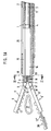
- Fig. 1
- einen Längsschnitt durch ein Ausführungsbeispiel des Werkzeugs, wobei die Fig. 1A den vorderen und Fig. 1B den hinteren Teil des Werkzeugs in einer ersten Arbeitsstellung zeigt,
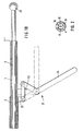
- Fig. 2
- eine Ansicht des Verschlussstückes mit der Nadelführung in Richtung des Pfeiles II in Fig. 1,
- Fig. 3
- eine gleiche Darstellung wie Fig. 1A, wobei das Werkzeug eine zweite Arbeitsstellung einnimmt,
- Fig. 4
- eine gleiche Darstellung wie Fig. 1A, wobei das Werkzeug eine dritte Arbeitsstellung einnimmt,
- Fig. 5
- eine Ansicht von Fig. 4 in Richtung des Pfeiles V,
- Fig. 6
- eine Draufsicht auf den vorderen Teil von Fig. 4 in Richtung des Pfeiles VI,
- Fig. 7
- eine Darstellung, welche das Einsetzen eines Schneidelementes zeigt und
- Fig. 8
- eine an einem visceralen Organ angebrachte Tabaksbeutelnaht.
- Fig. 9
- eine Seitenansicht einer Nadellafette,
- Fig.10
- eine Draufsicht auf eines der Enden der Nadellafette in Richtung des Pfeiles X in Fig. 9 und
- Fig.11
- eine Vorderansicht der Nadellafette in Richtung des Pfeiles XI in Fig. 9 in vergrösserter Darstellung.
- Fig. 1
- 2 shows a longitudinal section through an exemplary embodiment of the tool, FIG. 1A showing the front part and FIG. 1B the rear part of the tool in a first working position,
- Fig. 2
- 2 shows a view of the closure piece with the needle guide in the direction of arrow II in FIG. 1,
- Fig. 3
- a same representation as Fig. 1A, wherein the tool assumes a second working position,
- Fig. 4
- a same representation as Fig. 1A, wherein the tool assumes a third working position,
- Fig. 5
- 4 in the direction of arrow V,
- Fig. 6
- 4 shows a plan view of the front part of FIG. 4 in the direction of arrow VI,
- Fig. 7
- a representation showing the insertion of a cutting element and
- Fig. 8
- a tobacco pouch suture attached to a visceral organ.
- Fig. 9
- a side view of a needle mount,
- Fig. 10
- a plan view of one of the ends of the needle mount in the direction of arrow X in Fig. 9 and
- Fig. 11
- a front view of the needle mount in the direction of arrow XI in Fig. 9 in an enlarged view.
Tragendes Element des Werkzeugs ist ein ringzylindrisches Tragrohr 1. Auf dessen Aussenseite ist ein Verschlussrohr 2 und auf dessen Innenseite ist ein mit einer Kolbenstange 3 verbundener Kolben 4 achsial verschiebbar gelagert. Auf das Verschlussrohr 2 ist weiter eine im Querschnitt ringsegmentförmige Schale 5 (in Fig. 1A strichpunktiert gezeichnet) aufgesetzt. Die Schale 5 umgreift mit Reibschluss das Verschlussrohr 2 um mehr als 120° und ist um dieses dreh- und in jeder Drehlage feststellbar.The supporting element of the tool is a ring-
In das vordere Ende des Tragrohrs 1 ist ein Verschlussstück 6 fest eingesetzt. Dessen zylindrische Mantelflächenabschnitte sind bündig mit den Zylinderflächen des Tragrohrs 1.In the front end of the
Das Verschlussstück 6 ist mit zwei nach vorne gerichteten Lagern 7 versehen, an denen je eine Klemmbacke 9, 9' um eine Achse 8, 8' schwenkbar gelagert ist. Die Klemmbacken 9, 9' werden durch achsial auf die Achsen 8, 8' aufgesetzte, vorgespannte Schraubenfedern 10, 10' in ihrer in Fig. 1A aufgeklappten Stellung gehalten und gegen deren Wirkung geschlossen. Die Klemmbacken 9, 9' sind zweiteilig und bestehen aus einer starren, an der Achse 8 bzw. 8' angelenkten, U-Profil-förmigen Schiene 11 bzw. 11', die eine T- oder V-Nut bilden, in welche je eine gezahnte Matrize 12, 12' als Backenfutter einschiebbar ist. Die eingeschobene Matrize 12, 12' ist mit der Schiene 11, 11' fest aber lösbar verbunden. Die Verbindung kann form- und/oder kraftschlüssig sein. Sind die Matrizen 12, 12' in die Schienen 11, 11' vollständig eingeschoben und sind die Klemmbacken 9, 9' geschlossen (Fig. 3), liegt jedem Zahn der einen Matrize 12, 12' eine Ausnehmung in der anderen Matrize gegenüber, so dass zwischen den Matrizen 12, 12' ein zusammenhängender zickzackförmiger Zwischenraum 13 besteht. Damit sich im Bereich der Zähne die Klemmflächen 20 nicht verzahnen, sind die vordersten und hintersten Zähne der Matrizen 12, 12' als Anschläge gestaltet.The
Das Tragrohr 1 weist zwischen dem in der hinteren Endlage befindlichen Kolben 4 und dem Verschlussstück 6 ein Nadelmagazin 14 auf, in welches durch einen Schlitz 15 ein mit den Enden eines Fadens 17 verbundenes Nadelpaar 16 einlegbar ist (Fig. 3). Zur längsachsialen Führung der Nadeln 16 werden deren Spitzen in zwei entsprechende Bohrungen 18 im Verschlussstück 6 gesteckt, welche durch einen Schlitz 19 miteinander verbunden sind.The
Jede der Bohrungen 18 fluchtet mit einer entsprechenden Bohrung 18' in einer der beiden Matrizen 12, 12', welche Bohrungen 18' gegen die Klemmflächen 20 offen sind. Wie die Bohrungen 18 durch den Schlitz 19 sind dadurch bei geschlossenen Klemmbacken 9, 9' die Bohrungen 18' durch einen Schlitz 19' verbunden (Fig. 5).Each of the
Das Verschlussrohr 2 ist mittels eines Hebelmechanismus 21 (Fig. 1B) zwischen einer hinteren (Fig. 1A) und einer vorderen Endlage (Fig. 3 und 4) achsial auf dem Tragrohr 1 verschiebbar. Der Hebelmechanismus 21 ist einerseits an einer mit dem Verschlussrohr 2 fest verbundenen Lasche 22 und anderseits an einer mit dem Tragrohr 1 fest verbundenen Lasche 23 angelenkt. Ist ein Betätigungshebel 24 des Hebelmechanismus 21 nach unten geschwenkt (in Fig. 1B mit ausgezogenen Strichen gezeigt) ist das Verschlussrohr 2 in die hintere Endlage gezogen. Wird es nach oben verschwenkt (gestrichelt gezeichnet) verschiebt sich das Verschlussrohr 2 in seine vordere Endlage (Fig. 3 und 4), wo ein im Verschlussrohr 2 angebrachter Schlitz 25 mit dem Schlitz 15 des Tragrohrs fluchtet, so dass das Nadelmagazin 14 für das Einlegen der Nadeln 16 mit dem Faden 17 frei zugänglich ist. Nach dem Einlegen der Nadeln 16 wird das Nadelmagazin 14 durch ein Drehen der Schale 5 geschlossen.The
Die Kolbenstange 3 weist an ihrem rückwärtigen Ende einen kugeligen Handgriff 26 für das Verschieben des Kolbens 4 im Tragrohr 1 auf.The
Das Verschlussrohr 2 ist vorzugsweise gegen das Tragrohr 1 und das Tragrohr 1 gegen die Kolbenstange 3 mit einer nicht dargestellten Ringdichtung abgedichtet, wodurch, wenn das Werkzeug in die Bauch- oder Brusthöhle eingeführt ist, ein Abbau des Überdrucks verhindert wird.The sealing
Das beschriebene Werkzeug funktioniert wie folgt.The tool described works as follows.
Vorerst werden die dem zu behandelnden Organ entsprechenden, das heisst, mit gröberer oder feinerer Zahnung versehenen Matrizen 12, 12' in die Klemmbacken 9, 9' eingeschoben. Danach wird der Hebel 21 hochgeklappt und damit das Verschlussrohr 2 nach vorne über die Klemmbacken 9, 9' geschoben. Die Klemmbacken 9, 9' werden dabei geschlossen. Alsdann wird der Handgriff 26 nach hinten bewegt und der Kolben 4 aus dem Bereich des Nadelmagazins 14 gezogen. Nun wird die Schale 5 gedreht, bis das Nadelmagazin 14 frei zugänglich ist, worauf ein Nadelpaar 16 mit einem Faden 17 eingelegt wird und die Nadelspitzen in die Bohrungen 18 gesteckt werden. Nach dem Schliessen des Nadelmagazins 14 mit der Schale 5 ist das Werkzeug einsatzbereit und kann durch einen Trokar in die Bauch- oder Brusthöhle eingeführt werden.For the time being, the
Nach dem Einführen der Klemmbacken 9, 9' in die Bauchhöhle werden sie geöffnet indem der Hebel 24 nach unten verschwenkt und das Verschlussrohr 2 nach hinten gezogen wird. Dieses gibt dabei die Klemmbacken 9, 9' frei, die sich unter der Wirkung der Federn 10 öffnen. Nun kann das Werkzeug im Trokar verschoben werden, bis sich die gewünschte Stelle des zu behandelnden Organs 27 (Fig. 1A) zwischen den Klemmbacken 9, 9' befindet. Nimmt das Werkzeug diese Stellung ein, wird der Hebel 24 hoch geschwenkt, das heisst, die Klemmbacken 9, 9' werden wieder geschlossen und die Nahtstelle des Organs wird zwischen den Matrizen 12, 12' eingeklemmt. Danach wird der Kolben 4 nach Lösen einer Arretierung 4 mittels des Handgriffs 26 nach vorne vorgeschoben, wobei er die Nadeln 16 durch die Matrizen 12, 12' und damit durch die zwei in Zickzackfaltung aneinanderliegenden Wände des Organs 27 stösst, bis die Nadelspitzen über das freie Ende der Klemmbacken 9, 9' vorstehen. Anschliessend wird der Kolben 4 sofort wieder zurückgezogen, um ein Einklemmen des Fadens 17 zu vermeiden und um ein allfällig eingebautes (später beschriebenes) Schneidelement im Verschlussrohr 2 zu positionieren.After the clamping
Die Nadeln 16 werden alsdann mittels eines Werkzeugs an den Spitzen erfasst und vollständig aus den Klemmbacken 9, 9' herausgezogen. Anschliessend werden die Klemmbacken 9, 9' durch ein Verschwenken des Hebels 24 nach unten wieder geöffnet und das Werkzeug vom Organ 27 entfernt. Durch ein Festzurren des Fadens 17 kann nun das Organ 27 nach Art eines Tabaksbeutelverschlusses zusammengezogen und verschlossen werden. Der abgeschnürte Organteil kann danach mit einem Skalpell vom restlichen Organ abgetrennt werden. Zur Beschleunigung und Erleichterung dieses Vorganges kann, wie nachfolgend mit Bezug auf die Fig. 5 bis 8 beschrieben, das Werkzeug mit einem Schneidelement ausgerüstet werden.The
Gemäss den Fig. 5 bis 7 weist das Verschlussstück 6 einen kreissegmentförmigen Ausschnitt 28 auf, in den ein mit dem Kolben 4 fest verbundener Fortsatz 29 entsprechenden Querschnitts schiebbar ist. Der Fortsatz 29 ist mit einer Hinterschneidung 30 versehen, an welcher ein Schneidelement 31 mit einem komplementär gestalteten Verbindungsteil 32 formschlüssig einhängbar ist. Das Schneidelement 31 ist am freien Ende mit einer Schneide 33 versehen und weist, wie Fig. 5 zeigt, einen kreissegmentförmigen Querschnitt auf. Es wird durch die formschlüssige Verbindung mit dem Kolben 4 stets mit diesem hin und her bewegt und ist dabei einerseits an den Schienen 11, 11' der Klemmbacken 9, 9' und anderseits an der Innenwand des Verschlussrohres 2 geführt. Das Schneidelement 31 kann, wie Fig. 7 zeigt, in die Hinterschneidung 30 eingehängt (bzw. von dieser gelöst) werden, wenn das Verschlussrohr 2 in die hintere Endlage verschoben ist. Ist das Schneidelement 31 in das Werkzeug eingesetzt, wird jeweils, wenn während eines Kolbenvorschubs die Nadeln 16 durch die Matrizen 12, 12' bzw. durch die aneinander liegenden Organwände gestossen werden, gleichzeitig der abzutrennende Organteil vom im Körper verbleibenden Organ abgeschnitten. Diese Ausführungsform hat nebst einem Zeitgewinn den Vorteil, dass der Trennschnitt in einem stets gleichbleibenden, definierten Abstand von der Naht erfolgt.5 to 7, the
Beim Einlegen des Nadelpaares 16 und des Fadens 17 in das Nadelmagazin 14 ist darauf zu achten, dass der Faden 17 nicht verknotet oder hängenbleibt, wenn das Nadelpaar 16 durch den Kolben 4 ausgestossen wird. Um dies zu vermeiden und um das Instrument rascher einsatzbereit zu haben, ist die Verwendung einer Nadellafette gemäss den Fig. 9 bis 11 zweckmässig. Diese wird dem Chirurgen bestückt mit Nadeln und Faden als sterile Einwegpackung angeliefert. Die Nadellafette 35 ist ein länglicher, im Querschnitt rechteckiger Kunststoffkörper, der an beiden Enden mit einer Absetzung 36 und zudem mit einer Ausnehmung 37 versehen ist. In die Unterseite 38 des Körpers öffnen sich zwei achsparallele Längsschlitze 39, deren Flanken auf etwa halber Höhe durch eine zylindrische Ausweitung ein Nadellager 40 bilden. Der über dem Nadellager 40 befindliche Teil des Schlitzes 39 bildet einen Fadenkanal 41. Parallel über den Schlitzen 39 ist der Körper von zylindrischen Bohrungen 42, 43 durchsetzt, die als Fadenkammern den überwiegenden Teil des Fadens 17 aufnehmen. Zur Bestückung der Nadellafette mit dem an ihren Enden durch den Faden 17 verbundenen Nadelpaar 16 werden die Nadeln 16 mit ihrer Rückseite voran an der Vorderseite 44 des Körpers je in eines der Nadellager 40 eingeschoben und zwar so, dass die von den Nadelenden weglaufenden Fadenenden über den Nadeln 16 in den entsprechenden Fadenkanal 41 zu liegen kommen. Ist das Nadelpaar 16 vollständig in den Körper eingeschoben, bildet der Faden 17 an der Körpervorderseite 44 eine grosse Schlaufe, die von einem Fadenkanal 41 zum anderen führt. Diese Fadenschlaufe wird nun mit der Schlaufenmitte voran durch die Fadenkammer 42 geschoben und rückseitig herausgezogen, so dass nun an der Körperrückseite 45 eine kleinere Fadenschlaufe über die Fadenkammer 42 vorsteht. Diese kleinere Fadenschlaufe wird nun mit ihrer Mitte voran von der Rückseite 45 her in die zweite Fadenkammer 43 eingeschoben und darin vollständig verstaut. Die solcher Art bestückte Nadellafette wird alsdann mit der Vorderseite 44 voran in das Nadelmagazin 14 eingelegt, wobei das Nadelmagazin in seiner Querschnittsform so ausgelegt ist, dass die Nadellager 40 koachsial zu den Bohrungen 18 ausgerichtet sind. Dabei ist der Querschnitt des Kolbens 4 so auszubilden, dass er während des Vorschubes an der Nadellafette vorbei gleiten kann und gleichzeitig mit zwei seitab stehenden Nocken in die Schlitze 39 eingreift und dabei das Nadelpaar 16 ausstösst. Die Länge der Nocken ist dabei so bemessen, dass sie die Nadelenden hintergreifen ohne in die Farbkanäle 41 hineinzuragen. Die Ausnehmung 37 und die Absetzung 36 bieten während des Einschubs des Nadelpaares 16 Gewähr, dass der Faden 17 nicht zwischen der Stirnwand des Nadelmagazins 14 und der Vorderseite 44 der Nadellafette eingeklemmt wird. Die gleiche Ausbildung von Vorder- und Rückseite 44, 45 der Nadellafette hat beim Beschicken den Vorteil, dass das Nadelpaar 16 nicht von einer falschen Seite in das Nadellager 40 eingeschoben werden kann.When inserting the pair of
Claims (22)
Applications Claiming Priority (4)
| Application Number | Priority Date | Filing Date | Title |
|---|---|---|---|
| CH3997/92 | 1992-12-31 | ||
| CH399792A CH686025A5 (en) | 1992-12-31 | 1992-12-31 | Surgical clamping instrument for tobacco-pouch type suture |
| CH2340/93 | 1993-08-05 | ||
| CH234093A CH688465A5 (en) | 1993-08-05 | 1993-08-05 | Surgical clamping instrument for tobacco-pouch type suture |
Publications (1)
| Publication Number | Publication Date |
|---|---|
| EP0604789A1 true EP0604789A1 (en) | 1994-07-06 |
Family
ID=25690202
Family Applications (1)
| Application Number | Title | Priority Date | Filing Date |
|---|---|---|---|
| EP93119626A Withdrawn EP0604789A1 (en) | 1992-12-31 | 1993-12-06 | Surgical clamping element for making a purse string |
Country Status (3)
| Country | Link |
|---|---|
| US (1) | US5454822A (en) |
| EP (1) | EP0604789A1 (en) |
| JP (1) | JPH0723965A (en) |
Cited By (5)
| Publication number | Priority date | Publication date | Assignee | Title |
|---|---|---|---|---|
| DE102012103501A1 (en) | 2012-04-20 | 2013-10-24 | Medizinische Hochschule Hannover | Surgical device for producing purse-string stitch on hollow organ of human or animal, has needle guide channel that runs in region in arcuate manner so that corresponding arcuate stitch line is generated at hollow organ |
| CN105997175A (en) * | 2016-08-08 | 2016-10-12 | 苏州天臣国际医疗科技有限公司 | Tissue closing device and medical equipment |
| CN105997176A (en) * | 2016-08-08 | 2016-10-12 | 苏州天臣国际医疗科技有限公司 | Tissue closing device and medical equipment |
| WO2017114386A1 (en) * | 2015-12-31 | 2017-07-06 | 苏州天臣国际医疗科技有限公司 | Tissue closing device and medical instrument comprising tissue closing device |
| WO2018028134A1 (en) * | 2016-08-08 | 2018-02-15 | 苏州天臣国际医疗科技有限公司 | Tissue closing device and medical instrument |
Families Citing this family (472)
| Publication number | Priority date | Publication date | Assignee | Title |
|---|---|---|---|---|
| US6355050B1 (en) | 1992-12-10 | 2002-03-12 | Abbott Laboratories | Device and method for suturing tissue |
| US5527322A (en) | 1993-11-08 | 1996-06-18 | Perclose, Inc. | Device and method for suturing of internal puncture sites |
| US5562686A (en) * | 1995-04-19 | 1996-10-08 | United States Surgical Corporation | Apparaus and method for suturing body tissue |
| US5630825A (en) * | 1995-04-27 | 1997-05-20 | De La Torre; Roger A. | Magazine for loading a needle onto a stitching instrument and for loading a length of suture onto a suture dispensing instrument |
| US5755729A (en) * | 1995-04-27 | 1998-05-26 | General Surgical Innovations, Inc. | Magazine for loading a needle and a length of suture onto a surgical instrument |
| US5902311A (en) * | 1995-06-15 | 1999-05-11 | Perclose, Inc. | Low profile intraluminal suturing device and method |
| US5766183A (en) * | 1996-10-21 | 1998-06-16 | Lasersurge, Inc. | Vascular hole closure |
| US6042601A (en) * | 1998-03-18 | 2000-03-28 | United States Surgical Corporation | Apparatus for vascular hole closure |
| US7842048B2 (en) | 2006-08-18 | 2010-11-30 | Abbott Laboratories | Articulating suture device and method |
| US7235087B2 (en) | 1999-03-04 | 2007-06-26 | Abbott Park | Articulating suturing device and method |
| US7001400B1 (en) | 1999-03-04 | 2006-02-21 | Abbott Laboratories | Articulating suturing device and method |
| US6964668B2 (en) | 1999-03-04 | 2005-11-15 | Abbott Laboratories | Articulating suturing device and method |
| US20040092964A1 (en) | 1999-03-04 | 2004-05-13 | Modesitt D. Bruce | Articulating suturing device and method |
| US8137364B2 (en) | 2003-09-11 | 2012-03-20 | Abbott Laboratories | Articulating suturing device and method |
| US6358258B1 (en) | 1999-09-14 | 2002-03-19 | Abbott Laboratories | Device and method for performing end-to-side anastomosis |
| US6607227B1 (en) * | 2000-06-28 | 2003-08-19 | Siemens Automotive Corporation | Sawtooth terminal blade gripper and method of gripping |
| US6558399B1 (en) | 2000-06-30 | 2003-05-06 | Abbott Laboratories | Devices and method for handling a plurality of suture elements during a suturing procedure |
| US6730102B1 (en) | 2000-11-06 | 2004-05-04 | Abbott Laboratories | Systems, devices and methods for deploying needles |
| JP4351531B2 (en) * | 2001-10-22 | 2009-10-28 | インターヴェンショナル セラピーズ エルエルシー | Wound suture device |
| US20030078601A1 (en) * | 2001-10-22 | 2003-04-24 | Oleg Shikhman | Crimping and cutting device |
| US7160309B2 (en) | 2002-12-31 | 2007-01-09 | Laveille Kao Voss | Systems for anchoring a medical device in a body lumen |
| US20070084897A1 (en) | 2003-05-20 | 2007-04-19 | Shelton Frederick E Iv | Articulating surgical stapling instrument incorporating a two-piece e-beam firing mechanism |
| US9060770B2 (en) | 2003-05-20 | 2015-06-23 | Ethicon Endo-Surgery, Inc. | Robotically-driven surgical instrument with E-beam driver |
| US7462188B2 (en) | 2003-09-26 | 2008-12-09 | Abbott Laboratories | Device and method for suturing intracardiac defects |
| US7449024B2 (en) | 2003-12-23 | 2008-11-11 | Abbott Laboratories | Suturing device with split arm and method of suturing tissue |
| US11896225B2 (en) | 2004-07-28 | 2024-02-13 | Cilag Gmbh International | Staple cartridge comprising a pan |
| US8215531B2 (en) | 2004-07-28 | 2012-07-10 | Ethicon Endo-Surgery, Inc. | Surgical stapling instrument having a medical substance dispenser |
| US8083754B2 (en) | 2005-08-08 | 2011-12-27 | Abbott Laboratories | Vascular suturing device with needle capture |
| WO2007019016A1 (en) | 2005-08-08 | 2007-02-15 | Abbott Laboratories | Vascular suturing device |
| US7883517B2 (en) | 2005-08-08 | 2011-02-08 | Abbott Laboratories | Vascular suturing device |
| US9456811B2 (en) | 2005-08-24 | 2016-10-04 | Abbott Vascular Inc. | Vascular closure methods and apparatuses |
| US20070060895A1 (en) | 2005-08-24 | 2007-03-15 | Sibbitt Wilmer L Jr | Vascular closure methods and apparatuses |
| US8920442B2 (en) | 2005-08-24 | 2014-12-30 | Abbott Vascular Inc. | Vascular opening edge eversion methods and apparatuses |
| US10159482B2 (en) | 2005-08-31 | 2018-12-25 | Ethicon Llc | Fastener cartridge assembly comprising a fixed anvil and different staple heights |
| US11246590B2 (en) | 2005-08-31 | 2022-02-15 | Cilag Gmbh International | Staple cartridge including staple drivers having different unfired heights |
| US11484312B2 (en) | 2005-08-31 | 2022-11-01 | Cilag Gmbh International | Staple cartridge comprising a staple driver arrangement |
| US7669746B2 (en) | 2005-08-31 | 2010-03-02 | Ethicon Endo-Surgery, Inc. | Staple cartridges for forming staples having differing formed staple heights |
| US9237891B2 (en) | 2005-08-31 | 2016-01-19 | Ethicon Endo-Surgery, Inc. | Robotically-controlled surgical stapling devices that produce formed staples having different lengths |
| US7934630B2 (en) | 2005-08-31 | 2011-05-03 | Ethicon Endo-Surgery, Inc. | Staple cartridges for forming staples having differing formed staple heights |
| US20070106317A1 (en) | 2005-11-09 | 2007-05-10 | Shelton Frederick E Iv | Hydraulically and electrically actuated articulation joints for surgical instruments |
| US8820603B2 (en) | 2006-01-31 | 2014-09-02 | Ethicon Endo-Surgery, Inc. | Accessing data stored in a memory of a surgical instrument |
| US11278279B2 (en) | 2006-01-31 | 2022-03-22 | Cilag Gmbh International | Surgical instrument assembly |
| US7753904B2 (en) | 2006-01-31 | 2010-07-13 | Ethicon Endo-Surgery, Inc. | Endoscopic surgical instrument with a handle that can articulate with respect to the shaft |
| US7845537B2 (en) | 2006-01-31 | 2010-12-07 | Ethicon Endo-Surgery, Inc. | Surgical instrument having recording capabilities |
| US20110024477A1 (en) | 2009-02-06 | 2011-02-03 | Hall Steven G | Driven Surgical Stapler Improvements |
| US20120292367A1 (en) | 2006-01-31 | 2012-11-22 | Ethicon Endo-Surgery, Inc. | Robotically-controlled end effector |
| US8708213B2 (en) | 2006-01-31 | 2014-04-29 | Ethicon Endo-Surgery, Inc. | Surgical instrument having a feedback system |
| US11224427B2 (en) | 2006-01-31 | 2022-01-18 | Cilag Gmbh International | Surgical stapling system including a console and retraction assembly |
| US11793518B2 (en) | 2006-01-31 | 2023-10-24 | Cilag Gmbh International | Powered surgical instruments with firing system lockout arrangements |
| US20110290856A1 (en) | 2006-01-31 | 2011-12-01 | Ethicon Endo-Surgery, Inc. | Robotically-controlled surgical instrument with force-feedback capabilities |
| US8186555B2 (en) | 2006-01-31 | 2012-05-29 | Ethicon Endo-Surgery, Inc. | Motor-driven surgical cutting and fastening instrument with mechanical closure system |
| US8992422B2 (en) | 2006-03-23 | 2015-03-31 | Ethicon Endo-Surgery, Inc. | Robotically-controlled endoscopic accessory channel |
| US8322455B2 (en) | 2006-06-27 | 2012-12-04 | Ethicon Endo-Surgery, Inc. | Manually driven surgical cutting and fastening instrument |
| US9844649B2 (en) * | 2006-07-07 | 2017-12-19 | Cook Medical Technologies Llc | Telescopic wire guide |
| US8485412B2 (en) | 2006-09-29 | 2013-07-16 | Ethicon Endo-Surgery, Inc. | Surgical staples having attached drivers and stapling instruments for deploying the same |
| US10568652B2 (en) | 2006-09-29 | 2020-02-25 | Ethicon Llc | Surgical staples having attached drivers of different heights and stapling instruments for deploying the same |
| US8684253B2 (en) | 2007-01-10 | 2014-04-01 | Ethicon Endo-Surgery, Inc. | Surgical instrument with wireless communication between a control unit of a robotic system and remote sensor |
| US11291441B2 (en) | 2007-01-10 | 2022-04-05 | Cilag Gmbh International | Surgical instrument with wireless communication between control unit and remote sensor |
| US8652120B2 (en) | 2007-01-10 | 2014-02-18 | Ethicon Endo-Surgery, Inc. | Surgical instrument with wireless communication between control unit and sensor transponders |
| US11039836B2 (en) | 2007-01-11 | 2021-06-22 | Cilag Gmbh International | Staple cartridge for use with a surgical stapling instrument |
| US8701958B2 (en) | 2007-01-11 | 2014-04-22 | Ethicon Endo-Surgery, Inc. | Curved end effector for a surgical stapling device |
| US8727197B2 (en) | 2007-03-15 | 2014-05-20 | Ethicon Endo-Surgery, Inc. | Staple cartridge cavity configuration with cooperative surgical staple |
| US8893946B2 (en) | 2007-03-28 | 2014-11-25 | Ethicon Endo-Surgery, Inc. | Laparoscopic tissue thickness and clamp load measuring devices |
| CN101674777B (en) * | 2007-04-06 | 2012-09-05 | 介入治疗公司 | Suturing, crimping and cutting device |
| US11672531B2 (en) | 2007-06-04 | 2023-06-13 | Cilag Gmbh International | Rotary drive systems for surgical instruments |
| US8931682B2 (en) | 2007-06-04 | 2015-01-13 | Ethicon Endo-Surgery, Inc. | Robotically-controlled shaft based rotary drive systems for surgical instruments |
| US7753245B2 (en) | 2007-06-22 | 2010-07-13 | Ethicon Endo-Surgery, Inc. | Surgical stapling instruments |
| US8574244B2 (en) | 2007-06-25 | 2013-11-05 | Abbott Laboratories | System for closing a puncture in a vessel wall |
| US11849941B2 (en) | 2007-06-29 | 2023-12-26 | Cilag Gmbh International | Staple cartridge having staple cavities extending at a transverse angle relative to a longitudinal cartridge axis |
| US8636736B2 (en) | 2008-02-14 | 2014-01-28 | Ethicon Endo-Surgery, Inc. | Motorized surgical cutting and fastening instrument |
| US7819298B2 (en) | 2008-02-14 | 2010-10-26 | Ethicon Endo-Surgery, Inc. | Surgical stapling apparatus with control features operable with one hand |
| US7866527B2 (en) | 2008-02-14 | 2011-01-11 | Ethicon Endo-Surgery, Inc. | Surgical stapling apparatus with interlockable firing system |
| US8758391B2 (en) | 2008-02-14 | 2014-06-24 | Ethicon Endo-Surgery, Inc. | Interchangeable tools for surgical instruments |
| US9179912B2 (en) | 2008-02-14 | 2015-11-10 | Ethicon Endo-Surgery, Inc. | Robotically-controlled motorized surgical cutting and fastening instrument |
| US8573465B2 (en) | 2008-02-14 | 2013-11-05 | Ethicon Endo-Surgery, Inc. | Robotically-controlled surgical end effector system with rotary actuated closure systems |
| BRPI0901282A2 (en) | 2008-02-14 | 2009-11-17 | Ethicon Endo Surgery Inc | surgical cutting and fixation instrument with rf electrodes |
| US11272927B2 (en) | 2008-02-15 | 2022-03-15 | Cilag Gmbh International | Layer arrangements for surgical staple cartridges |
| US9615826B2 (en) | 2010-09-30 | 2017-04-11 | Ethicon Endo-Surgery, Llc | Multiple thickness implantable layers for surgical stapling devices |
| US9386983B2 (en) | 2008-09-23 | 2016-07-12 | Ethicon Endo-Surgery, Llc | Robotically-controlled motorized surgical instrument |
| US9005230B2 (en) | 2008-09-23 | 2015-04-14 | Ethicon Endo-Surgery, Inc. | Motorized surgical instrument |
| US11648005B2 (en) | 2008-09-23 | 2023-05-16 | Cilag Gmbh International | Robotically-controlled motorized surgical instrument with an end effector |
| US8210411B2 (en) | 2008-09-23 | 2012-07-03 | Ethicon Endo-Surgery, Inc. | Motor-driven surgical cutting instrument |
| US8608045B2 (en) | 2008-10-10 | 2013-12-17 | Ethicon Endo-Sugery, Inc. | Powered surgical cutting and stapling apparatus with manually retractable firing system |
| US8517239B2 (en) | 2009-02-05 | 2013-08-27 | Ethicon Endo-Surgery, Inc. | Surgical stapling instrument comprising a magnetic element driver |
| JP2012517287A (en) | 2009-02-06 | 2012-08-02 | エシコン・エンド−サージェリィ・インコーポレイテッド | Improvement of driven surgical stapler |
| US8444036B2 (en) | 2009-02-06 | 2013-05-21 | Ethicon Endo-Surgery, Inc. | Motor driven surgical fastener device with mechanisms for adjusting a tissue gap within the end effector |
| EP2442730A4 (en) * | 2009-06-19 | 2016-02-24 | Interventional Therapies | Crimping and cutting device |
| JP2011087911A (en) * | 2009-10-20 | 2011-05-06 | Rebo | Suturing instrument for laparoscopic operation, and cabinet for using the same |
| US8851354B2 (en) | 2009-12-24 | 2014-10-07 | Ethicon Endo-Surgery, Inc. | Surgical cutting instrument that analyzes tissue thickness |
| US8220688B2 (en) | 2009-12-24 | 2012-07-17 | Ethicon Endo-Surgery, Inc. | Motor-driven surgical cutting instrument with electric actuator directional control assembly |
| US8783543B2 (en) | 2010-07-30 | 2014-07-22 | Ethicon Endo-Surgery, Inc. | Tissue acquisition arrangements and methods for surgical stapling devices |
| NL2005359C2 (en) | 2010-08-22 | 2012-02-27 | Anton Jansen | DEVICE FOR REMOVING TISSUE. |
| US9370353B2 (en) | 2010-09-01 | 2016-06-21 | Abbott Cardiovascular Systems, Inc. | Suturing devices and methods |
| US8663252B2 (en) | 2010-09-01 | 2014-03-04 | Abbott Cardiovascular Systems, Inc. | Suturing devices and methods |
| US9351730B2 (en) | 2011-04-29 | 2016-05-31 | Ethicon Endo-Surgery, Llc | Tissue thickness compensator comprising channels |
| US9386988B2 (en) | 2010-09-30 | 2016-07-12 | Ethicon End-Surgery, LLC | Retainer assembly including a tissue thickness compensator |
| US9113865B2 (en) | 2010-09-30 | 2015-08-25 | Ethicon Endo-Surgery, Inc. | Staple cartridge comprising a layer |
| US9700317B2 (en) | 2010-09-30 | 2017-07-11 | Ethicon Endo-Surgery, Llc | Fastener cartridge comprising a releasable tissue thickness compensator |
| US11812965B2 (en) | 2010-09-30 | 2023-11-14 | Cilag Gmbh International | Layer of material for a surgical end effector |
| US9232941B2 (en) | 2010-09-30 | 2016-01-12 | Ethicon Endo-Surgery, Inc. | Tissue thickness compensator comprising a reservoir |
| US11298125B2 (en) | 2010-09-30 | 2022-04-12 | Cilag Gmbh International | Tissue stapler having a thickness compensator |
| US10945731B2 (en) | 2010-09-30 | 2021-03-16 | Ethicon Llc | Tissue thickness compensator comprising controlled release and expansion |
| US9629814B2 (en) | 2010-09-30 | 2017-04-25 | Ethicon Endo-Surgery, Llc | Tissue thickness compensator configured to redistribute compressive forces |
| US11925354B2 (en) | 2010-09-30 | 2024-03-12 | Cilag Gmbh International | Staple cartridge comprising staples positioned within a compressible portion thereof |
| US9364233B2 (en) | 2010-09-30 | 2016-06-14 | Ethicon Endo-Surgery, Llc | Tissue thickness compensators for circular surgical staplers |
| US8695866B2 (en) | 2010-10-01 | 2014-04-15 | Ethicon Endo-Surgery, Inc. | Surgical instrument having a power control circuit |
| WO2012149468A2 (en) * | 2011-04-29 | 2012-11-01 | University Of Southern California | Instruments and methods for the implantation of cell-seeded substrates |
| AU2012250197B2 (en) | 2011-04-29 | 2017-08-10 | Ethicon Endo-Surgery, Inc. | Staple cartridge comprising staples positioned within a compressible portion thereof |
| US9072535B2 (en) | 2011-05-27 | 2015-07-07 | Ethicon Endo-Surgery, Inc. | Surgical stapling instruments with rotatable staple deployment arrangements |
| US11207064B2 (en) | 2011-05-27 | 2021-12-28 | Cilag Gmbh International | Automated end effector component reloading system for use with a robotic system |
| US9044230B2 (en) | 2012-02-13 | 2015-06-02 | Ethicon Endo-Surgery, Inc. | Surgical cutting and fastening instrument with apparatus for determining cartridge and firing motion status |
| RU2644272C2 (en) | 2012-03-28 | 2018-02-08 | Этикон Эндо-Серджери, Инк. | Limitation node with tissue thickness compensator |
| JP6305979B2 (en) | 2012-03-28 | 2018-04-04 | エシコン・エンド−サージェリィ・インコーポレイテッドEthicon Endo−Surgery,Inc. | Tissue thickness compensator with multiple layers |
| BR112014024098B1 (en) | 2012-03-28 | 2021-05-25 | Ethicon Endo-Surgery, Inc. | staple cartridge |
| US8864778B2 (en) | 2012-04-10 | 2014-10-21 | Abbott Cardiovascular Systems, Inc. | Apparatus and method for suturing body lumens |
| US8858573B2 (en) | 2012-04-10 | 2014-10-14 | Abbott Cardiovascular Systems, Inc. | Apparatus and method for suturing body lumens |
| US9241707B2 (en) | 2012-05-31 | 2016-01-26 | Abbott Cardiovascular Systems, Inc. | Systems, methods, and devices for closing holes in body lumens |
| US9101358B2 (en) | 2012-06-15 | 2015-08-11 | Ethicon Endo-Surgery, Inc. | Articulatable surgical instrument comprising a firing drive |
| JP6290201B2 (en) | 2012-06-28 | 2018-03-07 | エシコン・エンド−サージェリィ・インコーポレイテッドEthicon Endo−Surgery,Inc. | Lockout for empty clip cartridge |
| US9408606B2 (en) | 2012-06-28 | 2016-08-09 | Ethicon Endo-Surgery, Llc | Robotically powered surgical device with manually-actuatable reversing system |
| US9204879B2 (en) | 2012-06-28 | 2015-12-08 | Ethicon Endo-Surgery, Inc. | Flexible drive member |
| US9289256B2 (en) | 2012-06-28 | 2016-03-22 | Ethicon Endo-Surgery, Llc | Surgical end effectors having angled tissue-contacting surfaces |
| US9282974B2 (en) | 2012-06-28 | 2016-03-15 | Ethicon Endo-Surgery, Llc | Empty clip cartridge lockout |
| BR112014032776B1 (en) | 2012-06-28 | 2021-09-08 | Ethicon Endo-Surgery, Inc | SURGICAL INSTRUMENT SYSTEM AND SURGICAL KIT FOR USE WITH A SURGICAL INSTRUMENT SYSTEM |
| US20140001231A1 (en) | 2012-06-28 | 2014-01-02 | Ethicon Endo-Surgery, Inc. | Firing system lockout arrangements for surgical instruments |
| US11202631B2 (en) | 2012-06-28 | 2021-12-21 | Cilag Gmbh International | Stapling assembly comprising a firing lockout |
| WO2014065688A1 (en) * | 2012-10-22 | 2014-05-01 | Gerbov Vitaly Vitalievich | Tissue dissection and ligation device |
| BR112015021098B1 (en) | 2013-03-01 | 2022-02-15 | Ethicon Endo-Surgery, Inc | COVERAGE FOR A JOINT JOINT AND SURGICAL INSTRUMENT |
| RU2669463C2 (en) | 2013-03-01 | 2018-10-11 | Этикон Эндо-Серджери, Инк. | Surgical instrument with soft stop |
| US9629629B2 (en) | 2013-03-14 | 2017-04-25 | Ethicon Endo-Surgey, LLC | Control systems for surgical instruments |
| US9883860B2 (en) | 2013-03-14 | 2018-02-06 | Ethicon Llc | Interchangeable shaft assemblies for use with a surgical instrument |
| BR112015026109B1 (en) | 2013-04-16 | 2022-02-22 | Ethicon Endo-Surgery, Inc | surgical instrument |
| US10136887B2 (en) | 2013-04-16 | 2018-11-27 | Ethicon Llc | Drive system decoupling arrangement for a surgical instrument |
| US9924942B2 (en) | 2013-08-23 | 2018-03-27 | Ethicon Llc | Motor-powered articulatable surgical instruments |
| MX369362B (en) | 2013-08-23 | 2019-11-06 | Ethicon Endo Surgery Llc | Firing member retraction devices for powered surgical instruments. |
| US9681870B2 (en) | 2013-12-23 | 2017-06-20 | Ethicon Llc | Articulatable surgical instruments with separate and distinct closing and firing systems |
| US9724092B2 (en) | 2013-12-23 | 2017-08-08 | Ethicon Llc | Modular surgical instruments |
| US9585662B2 (en) | 2013-12-23 | 2017-03-07 | Ethicon Endo-Surgery, Llc | Fastener cartridge comprising an extendable firing member |
| US9642620B2 (en) * | 2013-12-23 | 2017-05-09 | Ethicon Endo-Surgery, Llc | Surgical cutting and stapling instruments with articulatable end effectors |
| US20150173756A1 (en) | 2013-12-23 | 2015-06-25 | Ethicon Endo-Surgery, Inc. | Surgical cutting and stapling methods |
| US9839428B2 (en) | 2013-12-23 | 2017-12-12 | Ethicon Llc | Surgical cutting and stapling instruments with independent jaw control features |
| US9962161B2 (en) | 2014-02-12 | 2018-05-08 | Ethicon Llc | Deliverable surgical instrument |
| CN106232029B (en) | 2014-02-24 | 2019-04-12 | 伊西康内外科有限责任公司 | Fastening system including firing member locking piece |
| US20150272580A1 (en) | 2014-03-26 | 2015-10-01 | Ethicon Endo-Surgery, Inc. | Verification of number of battery exchanges/procedure count |
| US9820738B2 (en) | 2014-03-26 | 2017-11-21 | Ethicon Llc | Surgical instrument comprising interactive systems |
| BR112016021943B1 (en) | 2014-03-26 | 2022-06-14 | Ethicon Endo-Surgery, Llc | SURGICAL INSTRUMENT FOR USE BY AN OPERATOR IN A SURGICAL PROCEDURE |
| US9804618B2 (en) | 2014-03-26 | 2017-10-31 | Ethicon Llc | Systems and methods for controlling a segmented circuit |
| US9801628B2 (en) | 2014-09-26 | 2017-10-31 | Ethicon Llc | Surgical staple and driver arrangements for staple cartridges |
| US20150297222A1 (en) | 2014-04-16 | 2015-10-22 | Ethicon Endo-Surgery, Inc. | Fastener cartridges including extensions having different configurations |
| US11185330B2 (en) | 2014-04-16 | 2021-11-30 | Cilag Gmbh International | Fastener cartridge assemblies and staple retainer cover arrangements |
| BR112016023825B1 (en) | 2014-04-16 | 2022-08-02 | Ethicon Endo-Surgery, Llc | STAPLE CARTRIDGE FOR USE WITH A SURGICAL STAPLER AND STAPLE CARTRIDGE FOR USE WITH A SURGICAL INSTRUMENT |
| CN106456176B (en) | 2014-04-16 | 2019-06-28 | 伊西康内外科有限责任公司 | Fastener cartridge including the extension with various configuration |
| JP6532889B2 (en) | 2014-04-16 | 2019-06-19 | エシコン エルエルシーEthicon LLC | Fastener cartridge assembly and staple holder cover arrangement |
| US9636103B2 (en) * | 2014-08-28 | 2017-05-02 | Covidien Lp | Surgical suturing instrument |
| BR112017004361B1 (en) | 2014-09-05 | 2023-04-11 | Ethicon Llc | ELECTRONIC SYSTEM FOR A SURGICAL INSTRUMENT |
| US11311294B2 (en) | 2014-09-05 | 2022-04-26 | Cilag Gmbh International | Powered medical device including measurement of closure state of jaws |
| US10135242B2 (en) | 2014-09-05 | 2018-11-20 | Ethicon Llc | Smart cartridge wake up operation and data retention |
| US10105142B2 (en) | 2014-09-18 | 2018-10-23 | Ethicon Llc | Surgical stapler with plurality of cutting elements |
| MX2017003960A (en) | 2014-09-26 | 2017-12-04 | Ethicon Llc | Surgical stapling buttresses and adjunct materials. |
| US11523821B2 (en) | 2014-09-26 | 2022-12-13 | Cilag Gmbh International | Method for creating a flexible staple line |
| US10076325B2 (en) | 2014-10-13 | 2018-09-18 | Ethicon Llc | Surgical stapling apparatus comprising a tissue stop |
| US9924944B2 (en) | 2014-10-16 | 2018-03-27 | Ethicon Llc | Staple cartridge comprising an adjunct material |
| US11141153B2 (en) | 2014-10-29 | 2021-10-12 | Cilag Gmbh International | Staple cartridges comprising driver arrangements |
| US10517594B2 (en) | 2014-10-29 | 2019-12-31 | Ethicon Llc | Cartridge assemblies for surgical staplers |
| US9844376B2 (en) | 2014-11-06 | 2017-12-19 | Ethicon Llc | Staple cartridge comprising a releasable adjunct material |
| US10736636B2 (en) | 2014-12-10 | 2020-08-11 | Ethicon Llc | Articulatable surgical instrument system |
| US10085748B2 (en) | 2014-12-18 | 2018-10-02 | Ethicon Llc | Locking arrangements for detachable shaft assemblies with articulatable surgical end effectors |
| US9844374B2 (en) | 2014-12-18 | 2017-12-19 | Ethicon Llc | Surgical instrument systems comprising an articulatable end effector and means for adjusting the firing stroke of a firing member |
| RU2703684C2 (en) | 2014-12-18 | 2019-10-21 | ЭТИКОН ЭНДО-СЕРДЖЕРИ, ЭлЭлСи | Surgical instrument with anvil which is selectively movable relative to staple cartridge around discrete fixed axis |
| US9987000B2 (en) | 2014-12-18 | 2018-06-05 | Ethicon Llc | Surgical instrument assembly comprising a flexible articulation system |
| US9844375B2 (en) | 2014-12-18 | 2017-12-19 | Ethicon Llc | Drive arrangements for articulatable surgical instruments |
| US10188385B2 (en) | 2014-12-18 | 2019-01-29 | Ethicon Llc | Surgical instrument system comprising lockable systems |
| US10004501B2 (en) | 2014-12-18 | 2018-06-26 | Ethicon Llc | Surgical instruments with improved closure arrangements |
| US10321907B2 (en) | 2015-02-27 | 2019-06-18 | Ethicon Llc | System for monitoring whether a surgical instrument needs to be serviced |
| US10180463B2 (en) | 2015-02-27 | 2019-01-15 | Ethicon Llc | Surgical apparatus configured to assess whether a performance parameter of the surgical apparatus is within an acceptable performance band |
| US11154301B2 (en) | 2015-02-27 | 2021-10-26 | Cilag Gmbh International | Modular stapling assembly |
| US9808246B2 (en) | 2015-03-06 | 2017-11-07 | Ethicon Endo-Surgery, Llc | Method of operating a powered surgical instrument |
| US10441279B2 (en) | 2015-03-06 | 2019-10-15 | Ethicon Llc | Multiple level thresholds to modify operation of powered surgical instruments |
| US9993248B2 (en) | 2015-03-06 | 2018-06-12 | Ethicon Endo-Surgery, Llc | Smart sensors with local signal processing |
| US10052044B2 (en) | 2015-03-06 | 2018-08-21 | Ethicon Llc | Time dependent evaluation of sensor data to determine stability, creep, and viscoelastic elements of measures |
| JP2020121162A (en) | 2015-03-06 | 2020-08-13 | エシコン エルエルシーEthicon LLC | Time dependent evaluation of sensor data to determine stability element, creep element and viscoelastic element of measurement |
| US9901342B2 (en) | 2015-03-06 | 2018-02-27 | Ethicon Endo-Surgery, Llc | Signal and power communication system positioned on a rotatable shaft |
| US9924961B2 (en) | 2015-03-06 | 2018-03-27 | Ethicon Endo-Surgery, Llc | Interactive feedback system for powered surgical instruments |
| US10617412B2 (en) | 2015-03-06 | 2020-04-14 | Ethicon Llc | System for detecting the mis-insertion of a staple cartridge into a surgical stapler |
| US10245033B2 (en) | 2015-03-06 | 2019-04-02 | Ethicon Llc | Surgical instrument comprising a lockable battery housing |
| US10687806B2 (en) | 2015-03-06 | 2020-06-23 | Ethicon Llc | Adaptive tissue compression techniques to adjust closure rates for multiple tissue types |
| US10390825B2 (en) | 2015-03-31 | 2019-08-27 | Ethicon Llc | Surgical instrument with progressive rotary drive systems |
| US11058425B2 (en) | 2015-08-17 | 2021-07-13 | Ethicon Llc | Implantable layers for a surgical instrument |
| BR112018003693B1 (en) | 2015-08-26 | 2022-11-22 | Ethicon Llc | SURGICAL STAPLE CARTRIDGE FOR USE WITH A SURGICAL STAPPING INSTRUMENT |
| US10098642B2 (en) | 2015-08-26 | 2018-10-16 | Ethicon Llc | Surgical staples comprising features for improved fastening of tissue |
| MX2022006189A (en) | 2015-09-02 | 2022-06-16 | Ethicon Llc | Surgical staple configurations with camming surfaces located between portions supporting surgical staples. |
| US10238390B2 (en) | 2015-09-02 | 2019-03-26 | Ethicon Llc | Surgical staple cartridges with driver arrangements for establishing herringbone staple patterns |
| US10238386B2 (en) | 2015-09-23 | 2019-03-26 | Ethicon Llc | Surgical stapler having motor control based on an electrical parameter related to a motor current |
| US10327769B2 (en) | 2015-09-23 | 2019-06-25 | Ethicon Llc | Surgical stapler having motor control based on a drive system component |
| US10363036B2 (en) | 2015-09-23 | 2019-07-30 | Ethicon Llc | Surgical stapler having force-based motor control |
| US10105139B2 (en) | 2015-09-23 | 2018-10-23 | Ethicon Llc | Surgical stapler having downstream current-based motor control |
| US10299878B2 (en) | 2015-09-25 | 2019-05-28 | Ethicon Llc | Implantable adjunct systems for determining adjunct skew |
| US11890015B2 (en) | 2015-09-30 | 2024-02-06 | Cilag Gmbh International | Compressible adjunct with crossing spacer fibers |
| US10561420B2 (en) | 2015-09-30 | 2020-02-18 | Ethicon Llc | Tubular absorbable constructs |
| US10980539B2 (en) | 2015-09-30 | 2021-04-20 | Ethicon Llc | Implantable adjunct comprising bonded layers |
| US10285699B2 (en) | 2015-09-30 | 2019-05-14 | Ethicon Llc | Compressible adjunct |
| CN106913361B (en) * | 2015-12-28 | 2019-05-17 | 苏州天臣国际医疗科技有限公司 | Tissue closure component and medical instrument including the tissue closure component |
| US10292704B2 (en) | 2015-12-30 | 2019-05-21 | Ethicon Llc | Mechanisms for compensating for battery pack failure in powered surgical instruments |
| US10265068B2 (en) | 2015-12-30 | 2019-04-23 | Ethicon Llc | Surgical instruments with separable motors and motor control circuits |
| US10368865B2 (en) | 2015-12-30 | 2019-08-06 | Ethicon Llc | Mechanisms for compensating for drivetrain failure in powered surgical instruments |
| US10966717B2 (en) * | 2016-01-07 | 2021-04-06 | Covidien Lp | Surgical fastener apparatus |
| US11213293B2 (en) | 2016-02-09 | 2022-01-04 | Cilag Gmbh International | Articulatable surgical instruments with single articulation link arrangements |
| US10433837B2 (en) | 2016-02-09 | 2019-10-08 | Ethicon Llc | Surgical instruments with multiple link articulation arrangements |
| BR112018016098B1 (en) | 2016-02-09 | 2023-02-23 | Ethicon Llc | SURGICAL INSTRUMENT |
| US10258331B2 (en) | 2016-02-12 | 2019-04-16 | Ethicon Llc | Mechanisms for compensating for drivetrain failure in powered surgical instruments |
| US11224426B2 (en) | 2016-02-12 | 2022-01-18 | Cilag Gmbh International | Mechanisms for compensating for drivetrain failure in powered surgical instruments |
| US10448948B2 (en) | 2016-02-12 | 2019-10-22 | Ethicon Llc | Mechanisms for compensating for drivetrain failure in powered surgical instruments |
| US10617413B2 (en) | 2016-04-01 | 2020-04-14 | Ethicon Llc | Closure system arrangements for surgical cutting and stapling devices with separate and distinct firing shafts |
| US10485542B2 (en) | 2016-04-01 | 2019-11-26 | Ethicon Llc | Surgical stapling instrument comprising multiple lockouts |
| US10492783B2 (en) | 2016-04-15 | 2019-12-03 | Ethicon, Llc | Surgical instrument with improved stop/start control during a firing motion |
| US10456137B2 (en) | 2016-04-15 | 2019-10-29 | Ethicon Llc | Staple formation detection mechanisms |
| US11607239B2 (en) | 2016-04-15 | 2023-03-21 | Cilag Gmbh International | Systems and methods for controlling a surgical stapling and cutting instrument |
| US10426467B2 (en) | 2016-04-15 | 2019-10-01 | Ethicon Llc | Surgical instrument with detection sensors |
| US10357247B2 (en) | 2016-04-15 | 2019-07-23 | Ethicon Llc | Surgical instrument with multiple program responses during a firing motion |
| US10405859B2 (en) | 2016-04-15 | 2019-09-10 | Ethicon Llc | Surgical instrument with adjustable stop/start control during a firing motion |
| US10828028B2 (en) | 2016-04-15 | 2020-11-10 | Ethicon Llc | Surgical instrument with multiple program responses during a firing motion |
| US10335145B2 (en) | 2016-04-15 | 2019-07-02 | Ethicon Llc | Modular surgical instrument with configurable operating mode |
| US11179150B2 (en) | 2016-04-15 | 2021-11-23 | Cilag Gmbh International | Systems and methods for controlling a surgical stapling and cutting instrument |
| US11317917B2 (en) | 2016-04-18 | 2022-05-03 | Cilag Gmbh International | Surgical stapling system comprising a lockable firing assembly |
| US20170296173A1 (en) | 2016-04-18 | 2017-10-19 | Ethicon Endo-Surgery, Llc | Method for operating a surgical instrument |
| US10478181B2 (en) | 2016-04-18 | 2019-11-19 | Ethicon Llc | Cartridge lockout arrangements for rotary powered surgical cutting and stapling instruments |
| CN109310431B (en) | 2016-06-24 | 2022-03-04 | 伊西康有限责任公司 | Staple cartridge comprising wire staples and punch staples |
| US10675024B2 (en) | 2016-06-24 | 2020-06-09 | Ethicon Llc | Staple cartridge comprising overdriven staples |
| USD822206S1 (en) | 2016-06-24 | 2018-07-03 | Ethicon Llc | Surgical fastener |
| USD847989S1 (en) | 2016-06-24 | 2019-05-07 | Ethicon Llc | Surgical fastener cartridge |
| USD850617S1 (en) | 2016-06-24 | 2019-06-04 | Ethicon Llc | Surgical fastener cartridge |
| USD826405S1 (en) | 2016-06-24 | 2018-08-21 | Ethicon Llc | Surgical fastener |
| US10675025B2 (en) | 2016-12-21 | 2020-06-09 | Ethicon Llc | Shaft assembly comprising separately actuatable and retractable systems |
| US10675026B2 (en) | 2016-12-21 | 2020-06-09 | Ethicon Llc | Methods of stapling tissue |
| US10617414B2 (en) | 2016-12-21 | 2020-04-14 | Ethicon Llc | Closure member arrangements for surgical instruments |
| US20180168615A1 (en) | 2016-12-21 | 2018-06-21 | Ethicon Endo-Surgery, Llc | Method of deforming staples from two different types of staple cartridges with the same surgical stapling instrument |
| JP7010956B2 (en) | 2016-12-21 | 2022-01-26 | エシコン エルエルシー | How to staple tissue |
| US10426471B2 (en) | 2016-12-21 | 2019-10-01 | Ethicon Llc | Surgical instrument with multiple failure response modes |
| US10893864B2 (en) | 2016-12-21 | 2021-01-19 | Ethicon | Staple cartridges and arrangements of staples and staple cavities therein |
| CN110099619B (en) | 2016-12-21 | 2022-07-15 | 爱惜康有限责任公司 | Lockout device for surgical end effector and replaceable tool assembly |
| US10758229B2 (en) | 2016-12-21 | 2020-09-01 | Ethicon Llc | Surgical instrument comprising improved jaw control |
| US10588630B2 (en) | 2016-12-21 | 2020-03-17 | Ethicon Llc | Surgical tool assemblies with closure stroke reduction features |
| US11419606B2 (en) | 2016-12-21 | 2022-08-23 | Cilag Gmbh International | Shaft assembly comprising a clutch configured to adapt the output of a rotary firing member to two different systems |
| US10588632B2 (en) | 2016-12-21 | 2020-03-17 | Ethicon Llc | Surgical end effectors and firing members thereof |
| BR112019011947A2 (en) | 2016-12-21 | 2019-10-29 | Ethicon Llc | surgical stapling systems |
| US10682138B2 (en) | 2016-12-21 | 2020-06-16 | Ethicon Llc | Bilaterally asymmetric staple forming pocket pairs |
| US11684367B2 (en) | 2016-12-21 | 2023-06-27 | Cilag Gmbh International | Stepped assembly having and end-of-life indicator |
| US11134942B2 (en) | 2016-12-21 | 2021-10-05 | Cilag Gmbh International | Surgical stapling instruments and staple-forming anvils |
| US20180168648A1 (en) | 2016-12-21 | 2018-06-21 | Ethicon Endo-Surgery, Llc | Durability features for end effectors and firing assemblies of surgical stapling instruments |
| US10687810B2 (en) | 2016-12-21 | 2020-06-23 | Ethicon Llc | Stepped staple cartridge with tissue retention and gap setting features |
| US10856868B2 (en) | 2016-12-21 | 2020-12-08 | Ethicon Llc | Firing member pin configurations |
| US20180168608A1 (en) | 2016-12-21 | 2018-06-21 | Ethicon Endo-Surgery, Llc | Surgical instrument system comprising an end effector lockout and a firing assembly lockout |
| US10993715B2 (en) | 2016-12-21 | 2021-05-04 | Ethicon Llc | Staple cartridge comprising staples with different clamping breadths |
| US20180168625A1 (en) | 2016-12-21 | 2018-06-21 | Ethicon Endo-Surgery, Llc | Surgical stapling instruments with smart staple cartridges |
| US10517595B2 (en) | 2016-12-21 | 2019-12-31 | Ethicon Llc | Jaw actuated lock arrangements for preventing advancement of a firing member in a surgical end effector unless an unfired cartridge is installed in the end effector |
| US10945727B2 (en) | 2016-12-21 | 2021-03-16 | Ethicon Llc | Staple cartridge with deformable driver retention features |
| US10426449B2 (en) | 2017-02-16 | 2019-10-01 | Abbott Cardiovascular Systems, Inc. | Articulating suturing device with improved actuation and alignment mechanisms |
| US10624633B2 (en) | 2017-06-20 | 2020-04-21 | Ethicon Llc | Systems and methods for controlling motor velocity of a surgical stapling and cutting instrument |
| US10980537B2 (en) | 2017-06-20 | 2021-04-20 | Ethicon Llc | Closed loop feedback control of motor velocity of a surgical stapling and cutting instrument based on measured time over a specified number of shaft rotations |
| US10888321B2 (en) | 2017-06-20 | 2021-01-12 | Ethicon Llc | Systems and methods for controlling velocity of a displacement member of a surgical stapling and cutting instrument |
| USD879809S1 (en) | 2017-06-20 | 2020-03-31 | Ethicon Llc | Display panel with changeable graphical user interface |
| US11071554B2 (en) | 2017-06-20 | 2021-07-27 | Cilag Gmbh International | Closed loop feedback control of motor velocity of a surgical stapling and cutting instrument based on magnitude of velocity error measurements |
| US10646220B2 (en) | 2017-06-20 | 2020-05-12 | Ethicon Llc | Systems and methods for controlling displacement member velocity for a surgical instrument |
| US11382638B2 (en) | 2017-06-20 | 2022-07-12 | Cilag Gmbh International | Closed loop feedback control of motor velocity of a surgical stapling and cutting instrument based on measured time over a specified displacement distance |
| US11517325B2 (en) | 2017-06-20 | 2022-12-06 | Cilag Gmbh International | Closed loop feedback control of motor velocity of a surgical stapling and cutting instrument based on measured displacement distance traveled over a specified time interval |
| US10368864B2 (en) | 2017-06-20 | 2019-08-06 | Ethicon Llc | Systems and methods for controlling displaying motor velocity for a surgical instrument |
| US11653914B2 (en) | 2017-06-20 | 2023-05-23 | Cilag Gmbh International | Systems and methods for controlling motor velocity of a surgical stapling and cutting instrument according to articulation angle of end effector |
| US10813639B2 (en) | 2017-06-20 | 2020-10-27 | Ethicon Llc | Closed loop feedback control of motor velocity of a surgical stapling and cutting instrument based on system conditions |
| US10881396B2 (en) | 2017-06-20 | 2021-01-05 | Ethicon Llc | Surgical instrument with variable duration trigger arrangement |
| US10390841B2 (en) | 2017-06-20 | 2019-08-27 | Ethicon Llc | Control of motor velocity of a surgical stapling and cutting instrument based on angle of articulation |
| USD890784S1 (en) | 2017-06-20 | 2020-07-21 | Ethicon Llc | Display panel with changeable graphical user interface |
| US10307170B2 (en) | 2017-06-20 | 2019-06-04 | Ethicon Llc | Method for closed loop control of motor velocity of a surgical stapling and cutting instrument |
| US10327767B2 (en) | 2017-06-20 | 2019-06-25 | Ethicon Llc | Control of motor velocity of a surgical stapling and cutting instrument based on angle of articulation |
| USD879808S1 (en) | 2017-06-20 | 2020-03-31 | Ethicon Llc | Display panel with graphical user interface |
| US10881399B2 (en) | 2017-06-20 | 2021-01-05 | Ethicon Llc | Techniques for adaptive control of motor velocity of a surgical stapling and cutting instrument |
| US10779820B2 (en) | 2017-06-20 | 2020-09-22 | Ethicon Llc | Systems and methods for controlling motor speed according to user input for a surgical instrument |
| US11090046B2 (en) | 2017-06-20 | 2021-08-17 | Cilag Gmbh International | Systems and methods for controlling displacement member motion of a surgical stapling and cutting instrument |
| US10772629B2 (en) | 2017-06-27 | 2020-09-15 | Ethicon Llc | Surgical anvil arrangements |
| US11266405B2 (en) | 2017-06-27 | 2022-03-08 | Cilag Gmbh International | Surgical anvil manufacturing methods |
| US10993716B2 (en) | 2017-06-27 | 2021-05-04 | Ethicon Llc | Surgical anvil arrangements |
| US10856869B2 (en) | 2017-06-27 | 2020-12-08 | Ethicon Llc | Surgical anvil arrangements |
| US11324503B2 (en) | 2017-06-27 | 2022-05-10 | Cilag Gmbh International | Surgical firing member arrangements |
| US20180368844A1 (en) | 2017-06-27 | 2018-12-27 | Ethicon Llc | Staple forming pocket arrangements |
| US11678880B2 (en) | 2017-06-28 | 2023-06-20 | Cilag Gmbh International | Surgical instrument comprising a shaft including a housing arrangement |
| US11246592B2 (en) | 2017-06-28 | 2022-02-15 | Cilag Gmbh International | Surgical instrument comprising an articulation system lockable to a frame |
| US10903685B2 (en) | 2017-06-28 | 2021-01-26 | Ethicon Llc | Surgical shaft assemblies with slip ring assemblies forming capacitive channels |
| USD906355S1 (en) | 2017-06-28 | 2020-12-29 | Ethicon Llc | Display screen or portion thereof with a graphical user interface for a surgical instrument |
| US11564686B2 (en) | 2017-06-28 | 2023-01-31 | Cilag Gmbh International | Surgical shaft assemblies with flexible interfaces |
| US10716614B2 (en) | 2017-06-28 | 2020-07-21 | Ethicon Llc | Surgical shaft assemblies with slip ring assemblies with increased contact pressure |
| USD854151S1 (en) | 2017-06-28 | 2019-07-16 | Ethicon Llc | Surgical instrument shaft |
| US10765427B2 (en) | 2017-06-28 | 2020-09-08 | Ethicon Llc | Method for articulating a surgical instrument |
| EP3420947B1 (en) | 2017-06-28 | 2022-05-25 | Cilag GmbH International | Surgical instrument comprising selectively actuatable rotatable couplers |
| USD869655S1 (en) | 2017-06-28 | 2019-12-10 | Ethicon Llc | Surgical fastener cartridge |
| US10211586B2 (en) | 2017-06-28 | 2019-02-19 | Ethicon Llc | Surgical shaft assemblies with watertight housings |
| USD851762S1 (en) | 2017-06-28 | 2019-06-18 | Ethicon Llc | Anvil |
| US11259805B2 (en) | 2017-06-28 | 2022-03-01 | Cilag Gmbh International | Surgical instrument comprising firing member supports |
| US11020114B2 (en) | 2017-06-28 | 2021-06-01 | Cilag Gmbh International | Surgical instruments with articulatable end effector with axially shortened articulation joint configurations |
| US11007022B2 (en) | 2017-06-29 | 2021-05-18 | Ethicon Llc | Closed loop velocity control techniques based on sensed tissue parameters for robotic surgical instrument |
| US10932772B2 (en) | 2017-06-29 | 2021-03-02 | Ethicon Llc | Methods for closed loop velocity control for robotic surgical instrument |
| US10441272B2 (en) | 2017-06-29 | 2019-10-15 | Medos International Sarl | Suture magazine for suture passing surgical device |
| US10258418B2 (en) | 2017-06-29 | 2019-04-16 | Ethicon Llc | System for controlling articulation forces |
| US10398434B2 (en) | 2017-06-29 | 2019-09-03 | Ethicon Llc | Closed loop velocity control of closure member for robotic surgical instrument |
| US10898183B2 (en) | 2017-06-29 | 2021-01-26 | Ethicon Llc | Robotic surgical instrument with closed loop feedback techniques for advancement of closure member during firing |
| US11944300B2 (en) | 2017-08-03 | 2024-04-02 | Cilag Gmbh International | Method for operating a surgical system bailout |
| US11471155B2 (en) | 2017-08-03 | 2022-10-18 | Cilag Gmbh International | Surgical system bailout |
| US11304695B2 (en) | 2017-08-03 | 2022-04-19 | Cilag Gmbh International | Surgical system shaft interconnection |
| US10729501B2 (en) | 2017-09-29 | 2020-08-04 | Ethicon Llc | Systems and methods for language selection of a surgical instrument |
| US10765429B2 (en) | 2017-09-29 | 2020-09-08 | Ethicon Llc | Systems and methods for providing alerts according to the operational state of a surgical instrument |
| USD907647S1 (en) | 2017-09-29 | 2021-01-12 | Ethicon Llc | Display screen or portion thereof with animated graphical user interface |
| US10796471B2 (en) | 2017-09-29 | 2020-10-06 | Ethicon Llc | Systems and methods of displaying a knife position for a surgical instrument |
| USD917500S1 (en) | 2017-09-29 | 2021-04-27 | Ethicon Llc | Display screen or portion thereof with graphical user interface |
| US11399829B2 (en) | 2017-09-29 | 2022-08-02 | Cilag Gmbh International | Systems and methods of initiating a power shutdown mode for a surgical instrument |
| USD907648S1 (en) | 2017-09-29 | 2021-01-12 | Ethicon Llc | Display screen or portion thereof with animated graphical user interface |
| US10743872B2 (en) | 2017-09-29 | 2020-08-18 | Ethicon Llc | System and methods for controlling a display of a surgical instrument |
| US11134944B2 (en) | 2017-10-30 | 2021-10-05 | Cilag Gmbh International | Surgical stapler knife motion controls |
| US11090075B2 (en) | 2017-10-30 | 2021-08-17 | Cilag Gmbh International | Articulation features for surgical end effector |
| US10842490B2 (en) | 2017-10-31 | 2020-11-24 | Ethicon Llc | Cartridge body design with force reduction based on firing completion |
| US10779903B2 (en) | 2017-10-31 | 2020-09-22 | Ethicon Llc | Positive shaft rotation lock activated by jaw closure |
| US10779825B2 (en) | 2017-12-15 | 2020-09-22 | Ethicon Llc | Adapters with end effector position sensing and control arrangements for use in connection with electromechanical surgical instruments |
| US10869666B2 (en) | 2017-12-15 | 2020-12-22 | Ethicon Llc | Adapters with control systems for controlling multiple motors of an electromechanical surgical instrument |
| US10966718B2 (en) | 2017-12-15 | 2021-04-06 | Ethicon Llc | Dynamic clamping assemblies with improved wear characteristics for use in connection with electromechanical surgical instruments |
| US11006955B2 (en) | 2017-12-15 | 2021-05-18 | Ethicon Llc | End effectors with positive jaw opening features for use with adapters for electromechanical surgical instruments |
| US11033267B2 (en) | 2017-12-15 | 2021-06-15 | Ethicon Llc | Systems and methods of controlling a clamping member firing rate of a surgical instrument |
| US10743875B2 (en) | 2017-12-15 | 2020-08-18 | Ethicon Llc | Surgical end effectors with jaw stiffener arrangements configured to permit monitoring of firing member |
| US10687813B2 (en) | 2017-12-15 | 2020-06-23 | Ethicon Llc | Adapters with firing stroke sensing arrangements for use in connection with electromechanical surgical instruments |
| US11071543B2 (en) | 2017-12-15 | 2021-07-27 | Cilag Gmbh International | Surgical end effectors with clamping assemblies configured to increase jaw aperture ranges |
| US10828033B2 (en) | 2017-12-15 | 2020-11-10 | Ethicon Llc | Handheld electromechanical surgical instruments with improved motor control arrangements for positioning components of an adapter coupled thereto |
| US10743874B2 (en) | 2017-12-15 | 2020-08-18 | Ethicon Llc | Sealed adapters for use with electromechanical surgical instruments |
| US10779826B2 (en) | 2017-12-15 | 2020-09-22 | Ethicon Llc | Methods of operating surgical end effectors |
| US11197670B2 (en) | 2017-12-15 | 2021-12-14 | Cilag Gmbh International | Surgical end effectors with pivotal jaws configured to touch at their respective distal ends when fully closed |
| USD910847S1 (en) | 2017-12-19 | 2021-02-16 | Ethicon Llc | Surgical instrument assembly |
| US11045270B2 (en) | 2017-12-19 | 2021-06-29 | Cilag Gmbh International | Robotic attachment comprising exterior drive actuator |
| US10729509B2 (en) | 2017-12-19 | 2020-08-04 | Ethicon Llc | Surgical instrument comprising closure and firing locking mechanism |
| US10716565B2 (en) | 2017-12-19 | 2020-07-21 | Ethicon Llc | Surgical instruments with dual articulation drivers |
| US11020112B2 (en) | 2017-12-19 | 2021-06-01 | Ethicon Llc | Surgical tools configured for interchangeable use with different controller interfaces |
| US10835330B2 (en) | 2017-12-19 | 2020-11-17 | Ethicon Llc | Method for determining the position of a rotatable jaw of a surgical instrument attachment assembly |
| US11076853B2 (en) | 2017-12-21 | 2021-08-03 | Cilag Gmbh International | Systems and methods of displaying a knife position during transection for a surgical instrument |
| US11311290B2 (en) | 2017-12-21 | 2022-04-26 | Cilag Gmbh International | Surgical instrument comprising an end effector dampener |
| US11129680B2 (en) | 2017-12-21 | 2021-09-28 | Cilag Gmbh International | Surgical instrument comprising a projector |
| US11179151B2 (en) | 2017-12-21 | 2021-11-23 | Cilag Gmbh International | Surgical instrument comprising a display |
| CN108814680B (en) * | 2018-04-10 | 2019-06-25 | 中国人民解放军陆军军医大学第二附属医院 | Purse-string forceps for single-hole laparoscopic surgery |
| CN108338812A (en) * | 2018-04-17 | 2018-07-31 | 四川大学华西医院 | A kind of cold light source guiding stitching unstrument |
| US11583269B2 (en) | 2018-05-04 | 2023-02-21 | Arch Day Design, Llc | Suture passing device |
| WO2019213275A1 (en) * | 2018-05-04 | 2019-11-07 | Arch Day Design, Llc | Suture passing device |
| US11278274B2 (en) | 2018-05-04 | 2022-03-22 | Arch Day Design, Llc | Suture passing device |
| US10856870B2 (en) | 2018-08-20 | 2020-12-08 | Ethicon Llc | Switching arrangements for motor powered articulatable surgical instruments |
| US10842492B2 (en) | 2018-08-20 | 2020-11-24 | Ethicon Llc | Powered articulatable surgical instruments with clutching and locking arrangements for linking an articulation drive system to a firing drive system |
| US10912559B2 (en) | 2018-08-20 | 2021-02-09 | Ethicon Llc | Reinforced deformable anvil tip for surgical stapler anvil |
| US11253256B2 (en) | 2018-08-20 | 2022-02-22 | Cilag Gmbh International | Articulatable motor powered surgical instruments with dedicated articulation motor arrangements |
| USD914878S1 (en) | 2018-08-20 | 2021-03-30 | Ethicon Llc | Surgical instrument anvil |
| US10779821B2 (en) | 2018-08-20 | 2020-09-22 | Ethicon Llc | Surgical stapler anvils with tissue stop features configured to avoid tissue pinch |
| US11039834B2 (en) | 2018-08-20 | 2021-06-22 | Cilag Gmbh International | Surgical stapler anvils with staple directing protrusions and tissue stability features |
| US11045192B2 (en) | 2018-08-20 | 2021-06-29 | Cilag Gmbh International | Fabricating techniques for surgical stapler anvils |
| US11324501B2 (en) | 2018-08-20 | 2022-05-10 | Cilag Gmbh International | Surgical stapling devices with improved closure members |
| US11083458B2 (en) | 2018-08-20 | 2021-08-10 | Cilag Gmbh International | Powered surgical instruments with clutching arrangements to convert linear drive motions to rotary drive motions |
| US11207065B2 (en) | 2018-08-20 | 2021-12-28 | Cilag Gmbh International | Method for fabricating surgical stapler anvils |
| US11291440B2 (en) | 2018-08-20 | 2022-04-05 | Cilag Gmbh International | Method for operating a powered articulatable surgical instrument |
| US11219457B2 (en) | 2018-10-11 | 2022-01-11 | Covidien Lp | Laparoscopic purse string suture device |
| US11172929B2 (en) | 2019-03-25 | 2021-11-16 | Cilag Gmbh International | Articulation drive arrangements for surgical systems |
| US11696761B2 (en) | 2019-03-25 | 2023-07-11 | Cilag Gmbh International | Firing drive arrangements for surgical systems |
| US11147553B2 (en) | 2019-03-25 | 2021-10-19 | Cilag Gmbh International | Firing drive arrangements for surgical systems |
| US11147551B2 (en) | 2019-03-25 | 2021-10-19 | Cilag Gmbh International | Firing drive arrangements for surgical systems |
| US11253254B2 (en) | 2019-04-30 | 2022-02-22 | Cilag Gmbh International | Shaft rotation actuator on a surgical instrument |
| US11648009B2 (en) | 2019-04-30 | 2023-05-16 | Cilag Gmbh International | Rotatable jaw tip for a surgical instrument |
| US11452528B2 (en) | 2019-04-30 | 2022-09-27 | Cilag Gmbh International | Articulation actuators for a surgical instrument |
| US11432816B2 (en) | 2019-04-30 | 2022-09-06 | Cilag Gmbh International | Articulation pin for a surgical instrument |
| US11903581B2 (en) | 2019-04-30 | 2024-02-20 | Cilag Gmbh International | Methods for stapling tissue using a surgical instrument |
| US11426251B2 (en) | 2019-04-30 | 2022-08-30 | Cilag Gmbh International | Articulation directional lights on a surgical instrument |
| US11471157B2 (en) | 2019-04-30 | 2022-10-18 | Cilag Gmbh International | Articulation control mapping for a surgical instrument |
| US11246678B2 (en) | 2019-06-28 | 2022-02-15 | Cilag Gmbh International | Surgical stapling system having a frangible RFID tag |
| US11291451B2 (en) | 2019-06-28 | 2022-04-05 | Cilag Gmbh International | Surgical instrument with battery compatibility verification functionality |
| US11376098B2 (en) | 2019-06-28 | 2022-07-05 | Cilag Gmbh International | Surgical instrument system comprising an RFID system |
| US11684434B2 (en) | 2019-06-28 | 2023-06-27 | Cilag Gmbh International | Surgical RFID assemblies for instrument operational setting control |
| US11229437B2 (en) | 2019-06-28 | 2022-01-25 | Cilag Gmbh International | Method for authenticating the compatibility of a staple cartridge with a surgical instrument |
| US11627959B2 (en) | 2019-06-28 | 2023-04-18 | Cilag Gmbh International | Surgical instruments including manual and powered system lockouts |
| US11051807B2 (en) | 2019-06-28 | 2021-07-06 | Cilag Gmbh International | Packaging assembly including a particulate trap |
| US11464601B2 (en) | 2019-06-28 | 2022-10-11 | Cilag Gmbh International | Surgical instrument comprising an RFID system for tracking a movable component |
| US11497492B2 (en) | 2019-06-28 | 2022-11-15 | Cilag Gmbh International | Surgical instrument including an articulation lock |
| US11298127B2 (en) | 2019-06-28 | 2022-04-12 | Cilag GmbH Interational | Surgical stapling system having a lockout mechanism for an incompatible cartridge |
| US11399837B2 (en) | 2019-06-28 | 2022-08-02 | Cilag Gmbh International | Mechanisms for motor control adjustments of a motorized surgical instrument |
| US11219455B2 (en) | 2019-06-28 | 2022-01-11 | Cilag Gmbh International | Surgical instrument including a lockout key |
| US11638587B2 (en) | 2019-06-28 | 2023-05-02 | Cilag Gmbh International | RFID identification systems for surgical instruments |
| US11298132B2 (en) | 2019-06-28 | 2022-04-12 | Cilag GmbH Inlernational | Staple cartridge including a honeycomb extension |
| US11426167B2 (en) | 2019-06-28 | 2022-08-30 | Cilag Gmbh International | Mechanisms for proper anvil attachment surgical stapling head assembly |
| US11224497B2 (en) | 2019-06-28 | 2022-01-18 | Cilag Gmbh International | Surgical systems with multiple RFID tags |
| US11259803B2 (en) | 2019-06-28 | 2022-03-01 | Cilag Gmbh International | Surgical stapling system having an information encryption protocol |
| US11553971B2 (en) | 2019-06-28 | 2023-01-17 | Cilag Gmbh International | Surgical RFID assemblies for display and communication |
| US11771419B2 (en) | 2019-06-28 | 2023-10-03 | Cilag Gmbh International | Packaging for a replaceable component of a surgical stapling system |
| US11523822B2 (en) | 2019-06-28 | 2022-12-13 | Cilag Gmbh International | Battery pack including a circuit interrupter |
| US11660163B2 (en) | 2019-06-28 | 2023-05-30 | Cilag Gmbh International | Surgical system with RFID tags for updating motor assembly parameters |
| US11478241B2 (en) | 2019-06-28 | 2022-10-25 | Cilag Gmbh International | Staple cartridge including projections |
| US11246586B2 (en) | 2019-08-20 | 2022-02-15 | Arch Day Design, Llc | Instrument to manipulate and pass suture |
| US11446029B2 (en) | 2019-12-19 | 2022-09-20 | Cilag Gmbh International | Staple cartridge comprising projections extending from a curved deck surface |
| US11291447B2 (en) | 2019-12-19 | 2022-04-05 | Cilag Gmbh International | Stapling instrument comprising independent jaw closing and staple firing systems |
| US11931033B2 (en) | 2019-12-19 | 2024-03-19 | Cilag Gmbh International | Staple cartridge comprising a latch lockout |
| US11607219B2 (en) | 2019-12-19 | 2023-03-21 | Cilag Gmbh International | Staple cartridge comprising a detachable tissue cutting knife |
| US11464512B2 (en) | 2019-12-19 | 2022-10-11 | Cilag Gmbh International | Staple cartridge comprising a curved deck surface |
| US11701111B2 (en) | 2019-12-19 | 2023-07-18 | Cilag Gmbh International | Method for operating a surgical stapling instrument |
| US11504122B2 (en) | 2019-12-19 | 2022-11-22 | Cilag Gmbh International | Surgical instrument comprising a nested firing member |
| US11576672B2 (en) | 2019-12-19 | 2023-02-14 | Cilag Gmbh International | Surgical instrument comprising a closure system including a closure member and an opening member driven by a drive screw |
| US11529137B2 (en) | 2019-12-19 | 2022-12-20 | Cilag Gmbh International | Staple cartridge comprising driver retention members |
| US11529139B2 (en) | 2019-12-19 | 2022-12-20 | Cilag Gmbh International | Motor driven surgical instrument |
| US11911032B2 (en) | 2019-12-19 | 2024-02-27 | Cilag Gmbh International | Staple cartridge comprising a seating cam |
| US11234698B2 (en) | 2019-12-19 | 2022-02-01 | Cilag Gmbh International | Stapling system comprising a clamp lockout and a firing lockout |
| US11844520B2 (en) | 2019-12-19 | 2023-12-19 | Cilag Gmbh International | Staple cartridge comprising driver retention members |
| US11304696B2 (en) | 2019-12-19 | 2022-04-19 | Cilag Gmbh International | Surgical instrument comprising a powered articulation system |
| US11559304B2 (en) | 2019-12-19 | 2023-01-24 | Cilag Gmbh International | Surgical instrument comprising a rapid closure mechanism |
| US20210322002A1 (en) * | 2020-04-16 | 2021-10-21 | Covidien Lp | Surgical instrument for performing a purse string suture |
| USD975278S1 (en) | 2020-06-02 | 2023-01-10 | Cilag Gmbh International | Staple cartridge |
| USD966512S1 (en) | 2020-06-02 | 2022-10-11 | Cilag Gmbh International | Staple cartridge |
| USD975850S1 (en) | 2020-06-02 | 2023-01-17 | Cilag Gmbh International | Staple cartridge |
| USD974560S1 (en) | 2020-06-02 | 2023-01-03 | Cilag Gmbh International | Staple cartridge |
| USD976401S1 (en) | 2020-06-02 | 2023-01-24 | Cilag Gmbh International | Staple cartridge |
| USD967421S1 (en) | 2020-06-02 | 2022-10-18 | Cilag Gmbh International | Staple cartridge |
| USD975851S1 (en) | 2020-06-02 | 2023-01-17 | Cilag Gmbh International | Staple cartridge |
| US11666337B2 (en) * | 2020-07-08 | 2023-06-06 | Covidien Lp | Purse string suture instrument |
| US20220031350A1 (en) | 2020-07-28 | 2022-02-03 | Cilag Gmbh International | Surgical instruments with double pivot articulation joint arrangements |
| USD1013170S1 (en) | 2020-10-29 | 2024-01-30 | Cilag Gmbh International | Surgical instrument assembly |
| US11779330B2 (en) | 2020-10-29 | 2023-10-10 | Cilag Gmbh International | Surgical instrument comprising a jaw alignment system |
| US11717289B2 (en) | 2020-10-29 | 2023-08-08 | Cilag Gmbh International | Surgical instrument comprising an indicator which indicates that an articulation drive is actuatable |
| US11534259B2 (en) | 2020-10-29 | 2022-12-27 | Cilag Gmbh International | Surgical instrument comprising an articulation indicator |
| US11896217B2 (en) | 2020-10-29 | 2024-02-13 | Cilag Gmbh International | Surgical instrument comprising an articulation lock |
| US11617577B2 (en) | 2020-10-29 | 2023-04-04 | Cilag Gmbh International | Surgical instrument comprising a sensor configured to sense whether an articulation drive of the surgical instrument is actuatable |
| US11452526B2 (en) | 2020-10-29 | 2022-09-27 | Cilag Gmbh International | Surgical instrument comprising a staged voltage regulation start-up system |
| US11517390B2 (en) | 2020-10-29 | 2022-12-06 | Cilag Gmbh International | Surgical instrument comprising a limited travel switch |
| USD980425S1 (en) | 2020-10-29 | 2023-03-07 | Cilag Gmbh International | Surgical instrument assembly |
| US11844518B2 (en) | 2020-10-29 | 2023-12-19 | Cilag Gmbh International | Method for operating a surgical instrument |
| US11931025B2 (en) | 2020-10-29 | 2024-03-19 | Cilag Gmbh International | Surgical instrument comprising a releasable closure drive lock |
| US11627960B2 (en) | 2020-12-02 | 2023-04-18 | Cilag Gmbh International | Powered surgical instruments with smart reload with separately attachable exteriorly mounted wiring connections |
| US11944296B2 (en) | 2020-12-02 | 2024-04-02 | Cilag Gmbh International | Powered surgical instruments with external connectors |
| US11744581B2 (en) | 2020-12-02 | 2023-09-05 | Cilag Gmbh International | Powered surgical instruments with multi-phase tissue treatment |
| US11890010B2 (en) | 2020-12-02 | 2024-02-06 | Cllag GmbH International | Dual-sided reinforced reload for surgical instruments |
| US11653920B2 (en) | 2020-12-02 | 2023-05-23 | Cilag Gmbh International | Powered surgical instruments with communication interfaces through sterile barrier |
| US11849943B2 (en) | 2020-12-02 | 2023-12-26 | Cilag Gmbh International | Surgical instrument with cartridge release mechanisms |
| US11678882B2 (en) | 2020-12-02 | 2023-06-20 | Cilag Gmbh International | Surgical instruments with interactive features to remedy incidental sled movements |
| US11653915B2 (en) | 2020-12-02 | 2023-05-23 | Cilag Gmbh International | Surgical instruments with sled location detection and adjustment features |
| US11737751B2 (en) | 2020-12-02 | 2023-08-29 | Cilag Gmbh International | Devices and methods of managing energy dissipated within sterile barriers of surgical instrument housings |
| US20220183681A1 (en) * | 2020-12-15 | 2022-06-16 | Covidien Lp | Purse string suture passer device |
| US11812964B2 (en) | 2021-02-26 | 2023-11-14 | Cilag Gmbh International | Staple cartridge comprising a power management circuit |
| US11793514B2 (en) | 2021-02-26 | 2023-10-24 | Cilag Gmbh International | Staple cartridge comprising sensor array which may be embedded in cartridge body |
| US11730473B2 (en) | 2021-02-26 | 2023-08-22 | Cilag Gmbh International | Monitoring of manufacturing life-cycle |
| US11749877B2 (en) | 2021-02-26 | 2023-09-05 | Cilag Gmbh International | Stapling instrument comprising a signal antenna |
| US11751869B2 (en) | 2021-02-26 | 2023-09-12 | Cilag Gmbh International | Monitoring of multiple sensors over time to detect moving characteristics of tissue |
| US11723657B2 (en) | 2021-02-26 | 2023-08-15 | Cilag Gmbh International | Adjustable communication based on available bandwidth and power capacity |
| US11701113B2 (en) | 2021-02-26 | 2023-07-18 | Cilag Gmbh International | Stapling instrument comprising a separate power antenna and a data transfer antenna |
| US11925349B2 (en) | 2021-02-26 | 2024-03-12 | Cilag Gmbh International | Adjustment to transfer parameters to improve available power |
| US11696757B2 (en) | 2021-02-26 | 2023-07-11 | Cilag Gmbh International | Monitoring of internal systems to detect and track cartridge motion status |
| US11744583B2 (en) | 2021-02-26 | 2023-09-05 | Cilag Gmbh International | Distal communication array to tune frequency of RF systems |
| US11759202B2 (en) | 2021-03-22 | 2023-09-19 | Cilag Gmbh International | Staple cartridge comprising an implantable layer |
| US11806011B2 (en) | 2021-03-22 | 2023-11-07 | Cilag Gmbh International | Stapling instrument comprising tissue compression systems |
| US11826012B2 (en) | 2021-03-22 | 2023-11-28 | Cilag Gmbh International | Stapling instrument comprising a pulsed motor-driven firing rack |
| US11737749B2 (en) | 2021-03-22 | 2023-08-29 | Cilag Gmbh International | Surgical stapling instrument comprising a retraction system |
| US11717291B2 (en) | 2021-03-22 | 2023-08-08 | Cilag Gmbh International | Staple cartridge comprising staples configured to apply different tissue compression |
| US11723658B2 (en) | 2021-03-22 | 2023-08-15 | Cilag Gmbh International | Staple cartridge comprising a firing lockout |
| US11826042B2 (en) | 2021-03-22 | 2023-11-28 | Cilag Gmbh International | Surgical instrument comprising a firing drive including a selectable leverage mechanism |
| US11896219B2 (en) | 2021-03-24 | 2024-02-13 | Cilag Gmbh International | Mating features between drivers and underside of a cartridge deck |
| US11903582B2 (en) | 2021-03-24 | 2024-02-20 | Cilag Gmbh International | Leveraging surfaces for cartridge installation |
| US11944336B2 (en) | 2021-03-24 | 2024-04-02 | Cilag Gmbh International | Joint arrangements for multi-planar alignment and support of operational drive shafts in articulatable surgical instruments |
| US11793516B2 (en) | 2021-03-24 | 2023-10-24 | Cilag Gmbh International | Surgical staple cartridge comprising longitudinal support beam |
| US11786239B2 (en) | 2021-03-24 | 2023-10-17 | Cilag Gmbh International | Surgical instrument articulation joint arrangements comprising multiple moving linkage features |
| US11786243B2 (en) | 2021-03-24 | 2023-10-17 | Cilag Gmbh International | Firing members having flexible portions for adapting to a load during a surgical firing stroke |
| US11857183B2 (en) | 2021-03-24 | 2024-01-02 | Cilag Gmbh International | Stapling assembly components having metal substrates and plastic bodies |
| US11849944B2 (en) | 2021-03-24 | 2023-12-26 | Cilag Gmbh International | Drivers for fastener cartridge assemblies having rotary drive screws |
| US11896218B2 (en) | 2021-03-24 | 2024-02-13 | Cilag Gmbh International | Method of using a powered stapling device |
| US11832816B2 (en) | 2021-03-24 | 2023-12-05 | Cilag Gmbh International | Surgical stapling assembly comprising nonplanar staples and planar staples |
| US11849945B2 (en) | 2021-03-24 | 2023-12-26 | Cilag Gmbh International | Rotary-driven surgical stapling assembly comprising eccentrically driven firing member |
| US11744603B2 (en) | 2021-03-24 | 2023-09-05 | Cilag Gmbh International | Multi-axis pivot joints for surgical instruments and methods for manufacturing same |
| US20220378426A1 (en) | 2021-05-28 | 2022-12-01 | Cilag Gmbh International | Stapling instrument comprising a mounted shaft orientation sensor |
| WO2022269535A1 (en) * | 2021-06-24 | 2022-12-29 | Azurmeds Inc | Surgical instruments |
| CN113749711B (en) * | 2021-09-30 | 2023-07-04 | 南华大学附属第一医院 | Novel winding puncture auxiliary device for pancreatic and intestinal anastomosis |
| US11877745B2 (en) | 2021-10-18 | 2024-01-23 | Cilag Gmbh International | Surgical stapling assembly having longitudinally-repeating staple leg clusters |
| US11937816B2 (en) | 2021-10-28 | 2024-03-26 | Cilag Gmbh International | Electrical lead arrangements for surgical instruments |
Citations (5)
| Publication number | Priority date | Publication date | Assignee | Title |
|---|---|---|---|---|
| GB2081099A (en) * | 1980-08-04 | 1982-02-17 | Senco Products | Instrument for placing purse-string sutures |
| US4493323A (en) * | 1982-12-13 | 1985-01-15 | University Of Iowa Research Foundation | Suturing device and method for using same |
| EP0332591A1 (en) * | 1988-03-09 | 1989-09-13 | Harley International Medical Ltd. | Automatic instrument for pursestring sutures for surgical use |
| EP0369324A1 (en) * | 1988-11-11 | 1990-05-23 | United States Surgical Corporation | Surgical instrument |
| US4935027A (en) * | 1989-08-21 | 1990-06-19 | Inbae Yoon | Surgical suture instrument with remotely controllable suture material advancement |
Family Cites Families (7)
| Publication number | Priority date | Publication date | Assignee | Title |
|---|---|---|---|---|
| US3470875A (en) * | 1966-10-06 | 1969-10-07 | Alfred A Johnson | Surgical clamping and suturing instrument |
| US3807407A (en) * | 1971-06-07 | 1974-04-30 | E Schweizer | Suture applicator |
| US5037433A (en) * | 1990-05-17 | 1991-08-06 | Wilk Peter J | Endoscopic suturing device and related method and suture |
| US5147373A (en) * | 1991-04-29 | 1992-09-15 | Ferzli George S | Laparoscopic instrument |
| US5261917A (en) * | 1992-02-19 | 1993-11-16 | Hasson Harrith M | Suture tying forceps with a plurality of suture holders and method of tying a suture |
| US5342389A (en) * | 1992-04-28 | 1994-08-30 | Habley Medical Technology Corporation | Tissue manipulator |
| US5188636A (en) * | 1992-05-07 | 1993-02-23 | Ethicon, Inc. | Purse string suture instrument |
-
1993
- 1993-12-06 EP EP93119626A patent/EP0604789A1/en not_active Withdrawn
- 1993-12-22 US US08/171,611 patent/US5454822A/en not_active Expired - Fee Related
- 1993-12-28 JP JP5337203A patent/JPH0723965A/en active Pending
Patent Citations (5)
| Publication number | Priority date | Publication date | Assignee | Title |
|---|---|---|---|---|
| GB2081099A (en) * | 1980-08-04 | 1982-02-17 | Senco Products | Instrument for placing purse-string sutures |
| US4493323A (en) * | 1982-12-13 | 1985-01-15 | University Of Iowa Research Foundation | Suturing device and method for using same |
| EP0332591A1 (en) * | 1988-03-09 | 1989-09-13 | Harley International Medical Ltd. | Automatic instrument for pursestring sutures for surgical use |
| EP0369324A1 (en) * | 1988-11-11 | 1990-05-23 | United States Surgical Corporation | Surgical instrument |
| US4935027A (en) * | 1989-08-21 | 1990-06-19 | Inbae Yoon | Surgical suture instrument with remotely controllable suture material advancement |
Cited By (10)
| Publication number | Priority date | Publication date | Assignee | Title |
|---|---|---|---|---|
| DE102012103501A1 (en) | 2012-04-20 | 2013-10-24 | Medizinische Hochschule Hannover | Surgical device for producing purse-string stitch on hollow organ of human or animal, has needle guide channel that runs in region in arcuate manner so that corresponding arcuate stitch line is generated at hollow organ |
| DE102012103501B4 (en) * | 2012-04-20 | 2017-04-20 | Medizinische Hochschule Hannover | Surgical device for producing a purse-string suture |
| WO2017114386A1 (en) * | 2015-12-31 | 2017-07-06 | 苏州天臣国际医疗科技有限公司 | Tissue closing device and medical instrument comprising tissue closing device |
| CN106923876A (en) * | 2015-12-31 | 2017-07-07 | 苏州天臣国际医疗科技有限公司 | Tissue closing device and the medicine equipment including the tissue closing device |
| CN105997175A (en) * | 2016-08-08 | 2016-10-12 | 苏州天臣国际医疗科技有限公司 | Tissue closing device and medical equipment |
| CN105997176A (en) * | 2016-08-08 | 2016-10-12 | 苏州天臣国际医疗科技有限公司 | Tissue closing device and medical equipment |
| WO2018028134A1 (en) * | 2016-08-08 | 2018-02-15 | 苏州天臣国际医疗科技有限公司 | Tissue closing device and medical instrument |
| CN105997175B (en) * | 2016-08-08 | 2018-10-16 | 苏州天臣国际医疗科技有限公司 | tissue closing device and medical instrument |
| CN105997176B (en) * | 2016-08-08 | 2018-12-07 | 苏州天臣国际医疗科技有限公司 | tissue closing device and medical instrument |
| US11123072B2 (en) | 2016-08-08 | 2021-09-21 | Touchstone International Medical Science Co., Ltd. | Tissue closure device and medical instrument |
Also Published As
| Publication number | Publication date |
|---|---|
| JPH0723965A (en) | 1995-01-27 |
| US5454822A (en) | 1995-10-03 |
Similar Documents
| Publication | Publication Date | Title |
|---|---|---|
| EP0604789A1 (en) | Surgical clamping element for making a purse string | |
| DE69738199T2 (en) | sewing system | |
| DE3249678C2 (en) | Instrument for inserting a surgical fastener into body tissue | |
| DE60319443T2 (en) | Assembly of surgical stapling tool | |
| DE60225619T2 (en) | Subcutaneous suturing device for closing an opening of the abdominal wall of a patient | |
| DE3429845C2 (en) | Surgical stapler | |
| DE60310427T2 (en) | SURGICAL CLAMP DEVICE WITH A JOINT COUPLING AND A CLAMPING DEVICE | |
| DE4243427C1 (en) | System for applying knots in surgical sutures | |
| DE69825249T2 (en) | APPLICATOR FOR MOUNTING A SURGICAL CLIP IN TISSUE | |
| DE69530454T2 (en) | Endoscopic vascular suturing device | |
| DE4447658C2 (en) | Thread for constructing surgical seam | |
| DE60125771T2 (en) | DEVICE FOR THE OVERALL SELECTION OF AN ORGAN | |
| DE19711288B4 (en) | Applicator to hold and close a surgical clip | |
| DE3046365C2 (en) | Surgical suturing device for suturing hollow organs with metal clips | |
| EP0641178B1 (en) | Surgical suture instrument | |
| DE60216309T2 (en) | ENDOSCOPIC SYSTEM FOR APPLYING A VARIETY OF BLOOD VESSEL CLIPS | |
| DE69021441T3 (en) | Surgical stapling device. | |
| DE3029083C2 (en) | Surgical instrument for applying hemostatic forceps | |
| DE4137218C1 (en) | ||
| DE69722540T2 (en) | Surgical clamping mechanism | |
| DE3126121C2 (en) | Auxiliary device for making a bag seam on a tubular structure | |
| DE602004004194T2 (en) | Surgical stapling device with final release mechanism | |
| DE3141647C2 (en) | Surgical instrument for the application of clamps | |
| DE3249116C2 (en) | Surgical instrument | |
| DE60205580T2 (en) | Improved hypodermic needle and fluid injection device |
Legal Events
| Date | Code | Title | Description |
|---|---|---|---|
| PUAI | Public reference made under article 153(3) epc to a published international application that has entered the european phase |
Free format text: ORIGINAL CODE: 0009012 |
|
| AK | Designated contracting states |
Kind code of ref document: A1 Designated state(s): AT BE CH DE DK ES FR GB IT LI NL PT SE |
|
| 17P | Request for examination filed |
Effective date: 19941216 |
|
| 17Q | First examination report despatched |
Effective date: 19960925 |
|
| STAA | Information on the status of an ep patent application or granted ep patent |
Free format text: STATUS: THE APPLICATION IS DEEMED TO BE WITHDRAWN |
|
| 18D | Application deemed to be withdrawn |
Effective date: 19990220 |