EP0401466A1 - Laminate with diffraction structures - Google Patents
Laminate with diffraction structures Download PDFInfo
- Publication number
- EP0401466A1 EP0401466A1 EP90102997A EP90102997A EP0401466A1 EP 0401466 A1 EP0401466 A1 EP 0401466A1 EP 90102997 A EP90102997 A EP 90102997A EP 90102997 A EP90102997 A EP 90102997A EP 0401466 A1 EP0401466 A1 EP 0401466A1
- Authority
- EP
- European Patent Office
- Prior art keywords
- layer
- adhesive
- lacquer
- laminate according
- substrate
- Prior art date
- Legal status (The legal status is an assumption and is not a legal conclusion. Google has not performed a legal analysis and makes no representation as to the accuracy of the status listed.)
- Granted
Links
Images
Classifications
-
- B—PERFORMING OPERATIONS; TRANSPORTING
- B42—BOOKBINDING; ALBUMS; FILES; SPECIAL PRINTED MATTER
- B42D—BOOKS; BOOK COVERS; LOOSE LEAVES; PRINTED MATTER CHARACTERISED BY IDENTIFICATION OR SECURITY FEATURES; PRINTED MATTER OF SPECIAL FORMAT OR STYLE NOT OTHERWISE PROVIDED FOR; DEVICES FOR USE THEREWITH AND NOT OTHERWISE PROVIDED FOR; MOVABLE-STRIP WRITING OR READING APPARATUS
- B42D25/00—Information-bearing cards or sheet-like structures characterised by identification or security features; Manufacture thereof
- B42D25/40—Manufacture
- B42D25/45—Associating two or more layers
- B42D25/465—Associating two or more layers using chemicals or adhesives
- B42D25/47—Associating two or more layers using chemicals or adhesives using adhesives
-
- B—PERFORMING OPERATIONS; TRANSPORTING
- B42—BOOKBINDING; ALBUMS; FILES; SPECIAL PRINTED MATTER
- B42D—BOOKS; BOOK COVERS; LOOSE LEAVES; PRINTED MATTER CHARACTERISED BY IDENTIFICATION OR SECURITY FEATURES; PRINTED MATTER OF SPECIAL FORMAT OR STYLE NOT OTHERWISE PROVIDED FOR; DEVICES FOR USE THEREWITH AND NOT OTHERWISE PROVIDED FOR; MOVABLE-STRIP WRITING OR READING APPARATUS
- B42D25/00—Information-bearing cards or sheet-like structures characterised by identification or security features; Manufacture thereof
- B42D25/30—Identification or security features, e.g. for preventing forgery
- B42D25/309—Photographs
-
- B—PERFORMING OPERATIONS; TRANSPORTING
- B42—BOOKBINDING; ALBUMS; FILES; SPECIAL PRINTED MATTER
- B42D—BOOKS; BOOK COVERS; LOOSE LEAVES; PRINTED MATTER CHARACTERISED BY IDENTIFICATION OR SECURITY FEATURES; PRINTED MATTER OF SPECIAL FORMAT OR STYLE NOT OTHERWISE PROVIDED FOR; DEVICES FOR USE THEREWITH AND NOT OTHERWISE PROVIDED FOR; MOVABLE-STRIP WRITING OR READING APPARATUS
- B42D25/00—Information-bearing cards or sheet-like structures characterised by identification or security features; Manufacture thereof
- B42D25/30—Identification or security features, e.g. for preventing forgery
- B42D25/324—Reliefs
-
- B—PERFORMING OPERATIONS; TRANSPORTING
- B42—BOOKBINDING; ALBUMS; FILES; SPECIAL PRINTED MATTER
- B42D—BOOKS; BOOK COVERS; LOOSE LEAVES; PRINTED MATTER CHARACTERISED BY IDENTIFICATION OR SECURITY FEATURES; PRINTED MATTER OF SPECIAL FORMAT OR STYLE NOT OTHERWISE PROVIDED FOR; DEVICES FOR USE THEREWITH AND NOT OTHERWISE PROVIDED FOR; MOVABLE-STRIP WRITING OR READING APPARATUS
- B42D25/00—Information-bearing cards or sheet-like structures characterised by identification or security features; Manufacture thereof
- B42D25/30—Identification or security features, e.g. for preventing forgery
- B42D25/328—Diffraction gratings; Holograms
-
- B—PERFORMING OPERATIONS; TRANSPORTING
- B42—BOOKBINDING; ALBUMS; FILES; SPECIAL PRINTED MATTER
- B42D—BOOKS; BOOK COVERS; LOOSE LEAVES; PRINTED MATTER CHARACTERISED BY IDENTIFICATION OR SECURITY FEATURES; PRINTED MATTER OF SPECIAL FORMAT OR STYLE NOT OTHERWISE PROVIDED FOR; DEVICES FOR USE THEREWITH AND NOT OTHERWISE PROVIDED FOR; MOVABLE-STRIP WRITING OR READING APPARATUS
- B42D25/00—Information-bearing cards or sheet-like structures characterised by identification or security features; Manufacture thereof
- B42D25/30—Identification or security features, e.g. for preventing forgery
- B42D25/36—Identification or security features, e.g. for preventing forgery comprising special materials
-
- B—PERFORMING OPERATIONS; TRANSPORTING
- B42—BOOKBINDING; ALBUMS; FILES; SPECIAL PRINTED MATTER
- B42D—BOOKS; BOOK COVERS; LOOSE LEAVES; PRINTED MATTER CHARACTERISED BY IDENTIFICATION OR SECURITY FEATURES; PRINTED MATTER OF SPECIAL FORMAT OR STYLE NOT OTHERWISE PROVIDED FOR; DEVICES FOR USE THEREWITH AND NOT OTHERWISE PROVIDED FOR; MOVABLE-STRIP WRITING OR READING APPARATUS
- B42D25/00—Information-bearing cards or sheet-like structures characterised by identification or security features; Manufacture thereof
- B42D25/40—Manufacture
- B42D25/405—Marking
- B42D25/425—Marking by deformation, e.g. embossing
-
- B—PERFORMING OPERATIONS; TRANSPORTING
- B42—BOOKBINDING; ALBUMS; FILES; SPECIAL PRINTED MATTER
- B42D—BOOKS; BOOK COVERS; LOOSE LEAVES; PRINTED MATTER CHARACTERISED BY IDENTIFICATION OR SECURITY FEATURES; PRINTED MATTER OF SPECIAL FORMAT OR STYLE NOT OTHERWISE PROVIDED FOR; DEVICES FOR USE THEREWITH AND NOT OTHERWISE PROVIDED FOR; MOVABLE-STRIP WRITING OR READING APPARATUS
- B42D25/00—Information-bearing cards or sheet-like structures characterised by identification or security features; Manufacture thereof
- B42D25/40—Manufacture
- B42D25/45—Associating two or more layers
- B42D25/455—Associating two or more layers using heat
-
- G—PHYSICS
- G06—COMPUTING; CALCULATING OR COUNTING
- G06K—GRAPHICAL DATA READING; PRESENTATION OF DATA; RECORD CARRIERS; HANDLING RECORD CARRIERS
- G06K19/00—Record carriers for use with machines and with at least a part designed to carry digital markings
- G06K19/06—Record carriers for use with machines and with at least a part designed to carry digital markings characterised by the kind of the digital marking, e.g. shape, nature, code
- G06K19/06009—Record carriers for use with machines and with at least a part designed to carry digital markings characterised by the kind of the digital marking, e.g. shape, nature, code with optically detectable marking
- G06K19/06046—Constructional details
-
- G—PHYSICS
- G06—COMPUTING; CALCULATING OR COUNTING
- G06K—GRAPHICAL DATA READING; PRESENTATION OF DATA; RECORD CARRIERS; HANDLING RECORD CARRIERS
- G06K19/00—Record carriers for use with machines and with at least a part designed to carry digital markings
- G06K19/06—Record carriers for use with machines and with at least a part designed to carry digital markings characterised by the kind of the digital marking, e.g. shape, nature, code
- G06K19/08—Record carriers for use with machines and with at least a part designed to carry digital markings characterised by the kind of the digital marking, e.g. shape, nature, code using markings of different kinds or more than one marking of the same kind in the same record carrier, e.g. one marking being sensed by optical and the other by magnetic means
- G06K19/10—Record carriers for use with machines and with at least a part designed to carry digital markings characterised by the kind of the digital marking, e.g. shape, nature, code using markings of different kinds or more than one marking of the same kind in the same record carrier, e.g. one marking being sensed by optical and the other by magnetic means at least one kind of marking being used for authentication, e.g. of credit or identity cards
- G06K19/16—Record carriers for use with machines and with at least a part designed to carry digital markings characterised by the kind of the digital marking, e.g. shape, nature, code using markings of different kinds or more than one marking of the same kind in the same record carrier, e.g. one marking being sensed by optical and the other by magnetic means at least one kind of marking being used for authentication, e.g. of credit or identity cards the marking being a hologram or diffraction grating
-
- B42D2033/04—
-
- B42D2035/20—
-
- B—PERFORMING OPERATIONS; TRANSPORTING
- B42—BOOKBINDING; ALBUMS; FILES; SPECIAL PRINTED MATTER
- B42D—BOOKS; BOOK COVERS; LOOSE LEAVES; PRINTED MATTER CHARACTERISED BY IDENTIFICATION OR SECURITY FEATURES; PRINTED MATTER OF SPECIAL FORMAT OR STYLE NOT OTHERWISE PROVIDED FOR; DEVICES FOR USE THEREWITH AND NOT OTHERWISE PROVIDED FOR; MOVABLE-STRIP WRITING OR READING APPARATUS
- B42D25/00—Information-bearing cards or sheet-like structures characterised by identification or security features; Manufacture thereof
- B42D25/40—Manufacture
- B42D25/45—Associating two or more layers
- B42D25/465—Associating two or more layers using chemicals or adhesives
-
- Y—GENERAL TAGGING OF NEW TECHNOLOGICAL DEVELOPMENTS; GENERAL TAGGING OF CROSS-SECTIONAL TECHNOLOGIES SPANNING OVER SEVERAL SECTIONS OF THE IPC; TECHNICAL SUBJECTS COVERED BY FORMER USPC CROSS-REFERENCE ART COLLECTIONS [XRACs] AND DIGESTS
- Y10—TECHNICAL SUBJECTS COVERED BY FORMER USPC
- Y10S—TECHNICAL SUBJECTS COVERED BY FORMER USPC CROSS-REFERENCE ART COLLECTIONS [XRACs] AND DIGESTS
- Y10S283/00—Printed matter
- Y10S283/904—Credit card
-
- Y—GENERAL TAGGING OF NEW TECHNOLOGICAL DEVELOPMENTS; GENERAL TAGGING OF CROSS-SECTIONAL TECHNOLOGIES SPANNING OVER SEVERAL SECTIONS OF THE IPC; TECHNICAL SUBJECTS COVERED BY FORMER USPC CROSS-REFERENCE ART COLLECTIONS [XRACs] AND DIGESTS
- Y10—TECHNICAL SUBJECTS COVERED BY FORMER USPC
- Y10S—TECHNICAL SUBJECTS COVERED BY FORMER USPC CROSS-REFERENCE ART COLLECTIONS [XRACs] AND DIGESTS
- Y10S428/00—Stock material or miscellaneous articles
- Y10S428/914—Transfer or decalcomania
- Y10S428/915—Fraud or tamper detecting
-
- Y—GENERAL TAGGING OF NEW TECHNOLOGICAL DEVELOPMENTS; GENERAL TAGGING OF CROSS-SECTIONAL TECHNOLOGIES SPANNING OVER SEVERAL SECTIONS OF THE IPC; TECHNICAL SUBJECTS COVERED BY FORMER USPC CROSS-REFERENCE ART COLLECTIONS [XRACs] AND DIGESTS
- Y10—TECHNICAL SUBJECTS COVERED BY FORMER USPC
- Y10S—TECHNICAL SUBJECTS COVERED BY FORMER USPC CROSS-REFERENCE ART COLLECTIONS [XRACs] AND DIGESTS
- Y10S428/00—Stock material or miscellaneous articles
- Y10S428/916—Fraud or tamper detecting
-
- Y—GENERAL TAGGING OF NEW TECHNOLOGICAL DEVELOPMENTS; GENERAL TAGGING OF CROSS-SECTIONAL TECHNOLOGIES SPANNING OVER SEVERAL SECTIONS OF THE IPC; TECHNICAL SUBJECTS COVERED BY FORMER USPC CROSS-REFERENCE ART COLLECTIONS [XRACs] AND DIGESTS
- Y10—TECHNICAL SUBJECTS COVERED BY FORMER USPC
- Y10T—TECHNICAL SUBJECTS COVERED BY FORMER US CLASSIFICATION
- Y10T428/00—Stock material or miscellaneous articles
- Y10T428/24—Structurally defined web or sheet [e.g., overall dimension, etc.]
- Y10T428/24802—Discontinuous or differential coating, impregnation or bond [e.g., artwork, printing, retouched photograph, etc.]
- Y10T428/24826—Spot bonds connect components
-
- Y—GENERAL TAGGING OF NEW TECHNOLOGICAL DEVELOPMENTS; GENERAL TAGGING OF CROSS-SECTIONAL TECHNOLOGIES SPANNING OVER SEVERAL SECTIONS OF THE IPC; TECHNICAL SUBJECTS COVERED BY FORMER USPC CROSS-REFERENCE ART COLLECTIONS [XRACs] AND DIGESTS
- Y10—TECHNICAL SUBJECTS COVERED BY FORMER USPC
- Y10T—TECHNICAL SUBJECTS COVERED BY FORMER US CLASSIFICATION
- Y10T428/00—Stock material or miscellaneous articles
- Y10T428/24—Structurally defined web or sheet [e.g., overall dimension, etc.]
- Y10T428/24802—Discontinuous or differential coating, impregnation or bond [e.g., artwork, printing, retouched photograph, etc.]
- Y10T428/24917—Discontinuous or differential coating, impregnation or bond [e.g., artwork, printing, retouched photograph, etc.] including metal layer
-
- Y—GENERAL TAGGING OF NEW TECHNOLOGICAL DEVELOPMENTS; GENERAL TAGGING OF CROSS-SECTIONAL TECHNOLOGIES SPANNING OVER SEVERAL SECTIONS OF THE IPC; TECHNICAL SUBJECTS COVERED BY FORMER USPC CROSS-REFERENCE ART COLLECTIONS [XRACs] AND DIGESTS
- Y10—TECHNICAL SUBJECTS COVERED BY FORMER USPC
- Y10T—TECHNICAL SUBJECTS COVERED BY FORMER US CLASSIFICATION
- Y10T428/00—Stock material or miscellaneous articles
- Y10T428/26—Web or sheet containing structurally defined element or component, the element or component having a specified physical dimension
- Y10T428/263—Coating layer not in excess of 5 mils thick or equivalent
- Y10T428/264—Up to 3 mils
- Y10T428/265—1 mil or less
-
- Y—GENERAL TAGGING OF NEW TECHNOLOGICAL DEVELOPMENTS; GENERAL TAGGING OF CROSS-SECTIONAL TECHNOLOGIES SPANNING OVER SEVERAL SECTIONS OF THE IPC; TECHNICAL SUBJECTS COVERED BY FORMER USPC CROSS-REFERENCE ART COLLECTIONS [XRACs] AND DIGESTS
- Y10—TECHNICAL SUBJECTS COVERED BY FORMER USPC
- Y10T—TECHNICAL SUBJECTS COVERED BY FORMER US CLASSIFICATION
- Y10T428/00—Stock material or miscellaneous articles
- Y10T428/31504—Composite [nonstructural laminate]
- Y10T428/31551—Of polyamidoester [polyurethane, polyisocyanate, polycarbamate, etc.]
-
- Y—GENERAL TAGGING OF NEW TECHNOLOGICAL DEVELOPMENTS; GENERAL TAGGING OF CROSS-SECTIONAL TECHNOLOGIES SPANNING OVER SEVERAL SECTIONS OF THE IPC; TECHNICAL SUBJECTS COVERED BY FORMER USPC CROSS-REFERENCE ART COLLECTIONS [XRACs] AND DIGESTS
- Y10—TECHNICAL SUBJECTS COVERED BY FORMER USPC
- Y10T—TECHNICAL SUBJECTS COVERED BY FORMER US CLASSIFICATION
- Y10T428/00—Stock material or miscellaneous articles
- Y10T428/31504—Composite [nonstructural laminate]
- Y10T428/31652—Of asbestos
- Y10T428/31663—As siloxane, silicone or silane
-
- Y—GENERAL TAGGING OF NEW TECHNOLOGICAL DEVELOPMENTS; GENERAL TAGGING OF CROSS-SECTIONAL TECHNOLOGIES SPANNING OVER SEVERAL SECTIONS OF THE IPC; TECHNICAL SUBJECTS COVERED BY FORMER USPC CROSS-REFERENCE ART COLLECTIONS [XRACs] AND DIGESTS
- Y10—TECHNICAL SUBJECTS COVERED BY FORMER USPC
- Y10T—TECHNICAL SUBJECTS COVERED BY FORMER US CLASSIFICATION
- Y10T428/00—Stock material or miscellaneous articles
- Y10T428/31504—Composite [nonstructural laminate]
- Y10T428/31786—Of polyester [e.g., alkyd, etc.]
Definitions
- the invention relates to a layer composite of the type mentioned in the preamble of claim 1 and to a use of the layer composite according to claim 10.
- Such a layer composite is advantageously used to increase the security against forgery of documents of all kinds, the layer composite with its conspicuous optically variable patterns (optically variable device) being glued onto the document.
- the layer structure of differently designed hot stamping foils with holograms is e.g. B. from EP 170 832 A1. They are characterized by a carrier film and a layer composite, which comprises a separating layer, a lacquer layer which contains the hologram, and an adhesive layer.
- the separating layer connects the carrier film to the layer composite until it is glued to a substrate.
- the adhesive layer is heated through the carrier film, the separating layer and the lacquer layer and a high level of adhesion is achieved on the substrate. After gluing, the separating layer enables the carrier film to be easily detached from the layer composite, which is now firmly connected to the substrate.
- EP-253 089 A1 describes this technique for protecting optical markings, while the security of a paper ID card laminated between foils according to US Pat. No. 4,057,919 can be increased.
- the invention has for its object to provide a layer composite with optical diffraction structures for gluing to a substrate, which can be glued under the action of heat and the diffraction structures are destroyed when trying to detach the layer composite.
- 1 means a stabilization layer, on which an intermediate layer 2, a first lacquer layer 3, a reflective reflection layer 4, a second lacquer layer 5 and an adhesive layer 6 are applied in the order given.
- Layers 1 to 6 form a layer composite 7.
- Optical diffraction structures 8 are embedded between lacquer layers 3 and 5, e.g. B. grids, holograms, kinegrams, etc. With the adhesive layer 6, the layer composite 7 is attached to a substrate 9.
- the diffraction structures 8 are illuminated through the stabilization layer 1, the intermediate layer 2 and the lacquer layer 3. The diffracted and reflected light is reflected back through layers 1 to 3 to the viewer.
- the stabilization layer 1 advantageously consists of a heat-resistant, clear film of high optical quality.
- the film can be used in both a colorless and a colored version.
- polyester is very suitable as the film material, which is characterized not only by the high optical quality but also by high tensile strength and high temperature resistance.
- These foils are commercially available on rolls of various thicknesses, so that, as explained below, it is advantageous to build up the layer composite 7 on one side of the stabilization layer 1 by means of a rewinding system, not shown here.
- the foils advantageously have a thickness of 9 to 30 micrometers, so that on the one hand they are sufficiently strong and on the other hand they do not apply too strongly to the substrate 9.
- An adhesion promoter (primer) is applied over the entire surface of the stabilization layer 1 as the intermediate layer 2.
- the adhesion promoter creates a high level of adhesion between the stabilization layer 1 and the subsequent lacquer layer 3.
- a lacquer based on poly is advantageously used as the adhesion promoter urethane, so that the intermediate layer 2 is resistant to light, especially ultraviolet light, and to solvents.
- the intermediate layer 2 has an application thickness in the micrometer range, preferably 0.8 to 2 micrometers. Films that have already been coated with the intermediate layer 2 at the supplier can also advantageously be used for the stabilization layer 1.
- the lacquer layer 3 can also be applied directly to the stabilization layer 1 if the adhesion of the lacquer layer 3 to the film is sufficient.
- the adhesiveness can advantageously be achieved by pretreating the stabilization layer 1, e.g. B. in a corona or plasma discharge. A boundary layer between the lacquer layer 3 and the stabilization layer 1 or a surface layer of the film changed by the pretreatment takes over the function of the intermediate layer 2 in these examples.
- the first lacquer layer 3 is advantageously applied in at least one operation and has a layer thickness between 0.5 and 1.0 micrometers, preferably 0.6 micrometers.
- the reflection layer 4 is then applied to the lacquer layer 3, which is advantageously pretreated by means of a corona discharge in order to bring about a good adhesion of the reflection layer 4 to the lacquer layer 3.
- a metal is preferably vapor-deposited as the reflection layer 4, for example aluminum, which is inexpensive and reflects visible and infrared light well even in thin layers.
- a thickness of less than 30 nanometers is sufficient for a metallic reflection layer 4; for aluminum it is about 15 nanometers.
- a dielectric is also advantageously suitable as the reflection layer 4, with a refractive index that differs as strongly as possible from the adjacent layers 3 and 5, since the diffraction structures 8 are partially transparent and materials underneath, e.g. B. a picture, not completely obscure.
- the relief profile at least one optical diffraction structure 8 with a heated matrix is embossed through the reflection layer 4 into the lacquer layer 3.
- a predetermined number of diffraction structures 8 are advantageously impressed simultaneously at right angles to the running direction of the film strip.
- the relief of the diffraction structures 8 has a typical profile height of approximately 0.5 micrometers.
- the same thermoplastic material, for example an acrylic polymer lacquer, is advantageously used for both lacquer layers 3 and 5.
- the acrylic polymer lacquer is selected such that the mechanical stresses remaining in the lacquer layer 3 from embossing destroy the diffraction structures 8 impressed in the lacquer layer 3 when heated in the range from 150 ° to 160 ° C.
- the acrylic polymer lacquer of the lacquer layer 3 can be colored in such a way that it is transparent at least in a predetermined part of the light spectrum.
- the diffraction structure 8 remains machine or visually readable in a predetermined color. If, for example, the dye is only permeable to infrared light, the diffraction structure 8 is hidden from the unarmed eye and can only be recognized by means of a reading device, not shown here, which can determine the presence of the diffraction structure 8.
- the layer thickness of the adhesive layer 6 is advantageously adapted to the surface properties of the substrate 9. With smooth substrates 9, such as. B. in photo papers, 3 microns thickness of the adhesive layer 6 while the adhesive layer 6 advantageously has a thickness of 6 micrometers or more in the case of a rough substrate 9. In the case of paper with a normal surface structure, for example, the thickness of the adhesive layer 6 is approximately 5 micrometers.
- Suitable for the adhesive layer 6 are heat-activated hot-melt adhesives, e.g. B. on the basis of polymethyl methacrylate, which develop their adhesive strength when heated from about 110 ° C.
- the layer composite 7 can only be detached from the substrate 9 at a temperature of the hot-melt adhesive of more than 170 ° C. without excessive tensile forces which destroy the layers 3 to 5 occurring in the layer composite 7.
- the adhesive layer 6 When gluing, the adhesive layer 6 is heated by the stabilization layer 1, the stabilization layer 1 distributing the heat supplied and supplying it evenly to the layers 3 to 6. Temperatures of up to 140 ° C. can be reached in the adhesive layer 6 without the diffraction structure 8 being damaged.
- the hot glue of the adhesive layer 6 matched to these temperatures bond intimately to the substrate 9 and, after cooling, has such a large adhesive force that, for. B. the paper substrate 9 is damaged in a detachment attempt.
- a detachment of the layer composite 7 at 170 ° C. is useless since, despite the stabilization layer 1, the impressed diffraction structures 8 in the lacquer layers 3, 5 are irreversibly thermally destroyed even at temperatures between 150 and 160 ° C. If the temperatures during the detachment attempt are slightly below 170 ° C, the tensile forces destroy the soft layers 3 to 5.
- the finished layer composite 7 leaves the rewinding system, for example in the form of a roll, which has graphic compositions of diffraction structures 8.
- a partial area, the z. B. contains a self-contained predetermined composition of the diffraction structures 8, is advantageously punched out or cut out of the layer composite 7 as a mark 10 ( Figure 2).
- the brand 10 is on the Substrate 9 arranged.
- a heatable stamp not shown here, heats the adhesive layer 6 through the layers 1 to 5 until the adhesive layer 6 softens and adheres to the substrate 9. After the hot glue has solidified, the mark 10 is firmly connected to the substrate 9.
- the mark 10 has a circular shape of 2 cm in diameter and is typically 25 micrometers thick.
- the marks 10 can also be cut out in other sizes and have oval, rectangular or other shapes of the border. Their shape and dimensions are e.g. B. predetermined by the graphic composition of the diffraction structures 8 ( Figure 1).
- Suitable substrates 9 are, for example, papers or plastics with different surface properties, such as occur with photo papers, ID cards, documents, securities, banknotes etc.
- the layer composite 7 (FIG. 1) additionally has the stabilization layer 1 and the intermediate layer 2, which are cut out with the layers 3 to 6 and transferred to the substrate 9.
- These two layers 1, 2 have the advantage that the occurrence of overheated areas, in which the temperature is more than 150 ° C., is avoided in layers 3 to 5, in which local thermal destruction of the diffraction structure 8 is possible would.
- the stabilization layer 1 is heat-resistant enough to mechanically support the layers 3 to 5, which are very sensitive at about 140 ° C., so that the mechanical pressure or shear forces that inevitably occur during the gluing process do not destroy the diffraction structure 8.
- the stabilization layer 1 enables the label 10 to be stuck on with an advantageously matched hot glue at a temperature which is very close, but below the destruction temperature of the diffraction structure 8, from 150 ° C. to 160 ° C., while the detachment from the substrate 9 only occurs clearly at one higher Temperature is possible.
- the tensile forces used in a detachment attempt are transferred to the layers 3 to 6 at lower temperatures.
- the tensile forces mechanically destroy the diffraction structures 8.
- a detachment attempt with chemical solvents for the hot glue of the adhesive layer 6 is also unsuccessful since these also destroy the lacquer layers 3 and 5.
- the stabilization layer 1 advantageously also prevents mechanical damage to the diffraction structure 8 during the use of the substrate 9 secured by means of the mark 10 (FIG. 2).
- the stabilization layer 1 advantageously has a cold adhesive layer 11 (FIG. 2) on the side facing away from the intermediate layer 2, so that the stamps 10 after punching out in a predetermined order and orientation only using pressure can be glued onto a carrier 12, for example onto a siliconized paper or onto a clear polyester film coated with silicone.
- This polyester film has the advantage that the marks 10 are visible through the carrier 12 and therefore they can be arranged precisely on the substrate 9 before being glued on.
- the z. B. wound into a roll carrier 12 with the marks 10 is easily transportable to a sticking machine, not shown here.
- Each mark 10 is individually heated through the carrier 12 to the adhesive temperature and glued to the substrate 9.
- the cold adhesive layer 11 does not change, so that the siliconized carrier 12 can easily be separated from the mark 10.
- the mark 10 can be removed from the carrier 12 and glued with the cold adhesive layer 11 on the hot glue side of a clear laminating film, such as are used for the hot lamination of book covers and ID cards of all kinds.
- the cold adhesive layer 11 fixes the mark 10 until the laminating film and the mark 10 are applied simultaneously using heat are connected to the substrate 9.
- the stabilization layer 1 advantageously also prevents the thermal destruction of the diffraction structures 8 during hot lamination, as is observed with brands 10 according to the prior art.
- the entire band-shaped layer composite 7 (FIG. 1) with the cold adhesive layer 11 (FIG. 2) is advantageously bonded directly to the band-shaped carrier 12.
- the part of the layer composite 7 which is not required and which no longer contains marks 10 is, for. B. deducted from the carrier 12. Until further processing, the carrier 12 stuck with the marks 10 can advantageously be stored as a roll.
- the cold adhesive layer 11 has a thickness in the range from 5 to 30 micrometers. Suitable cold adhesives are those which are practically colorless in this thickness and do not interfere with viewing the diffraction structure 8.
- the carrier 12 is advantageously the clear laminating film itself, which has a transparent hot-melt adhesive layer 13.
- the marks 10 are glued to the hot glue layer 13 with the cold glue layer 11. Since the mark 10 is visible through the clear laminating film, an exact positioning of the mark 10 on the substrate 9 is possible immediately before the adhesive is applied.
- the clear laminating film and the mark 10 are laminated in the usual manner at approximately 120 to 140 ° C. on the substrate 9, the hot-melt adhesive layer 13 and the adhesive layer 6 being bonded to the substrate 9. After the adhesive has been applied, the hot-melt adhesive layer 13 is crystal clear and therefore does not impair viewing of the diffraction structures 8 (FIG. 1).
- the laminating film and the hot-melt adhesive layer 13 can be colored and act as a color filter, or advantageously also colorless, in order not to impair the conspicuous play of the diffraction colors. Because of its high tensile strength and temperature resistance, polyester is advantageous as Material for the laminating film, the thickness of which is approximately 80 to 300 micrometers.
- the hot-melt adhesive layer 13 has a thickness of 80 to 300 micrometers and consists, for example, of polypropylene.
- the adhesion promoter in the intermediate layer 2 (FIG. 3) is not applied over the entire area, but only in adhesive zones 14.
- the adhesive zones 14 form a predetermined pattern on the stabilization layer 1.
- Intermediate zones 15 with a low adhesive strength separate the adhesive zones 14 from each other.
- the intermediate layer 2 has a high adhesive capacity between the stabilization layer 1 and the subsequent lacquer layer 3 only in the adhesive zones 14.
- the intermediate zones 15 are advantageously filled with a release agent in order to achieve good optical contact between the stabilization layer 1 and the lacquer layer 3.
- the adhesion promoter and the release agent have approximately the same application heights.
- the release agent prevents the stabilization layer 1 from adhering to the lacquer layer 3 in the intermediate zones 15.
- the intermediate layer 2 has a locally variable adhesiveness, when trying to detach the layer composite 7 from the substrate 9, the detachment force is only transferred to the layers 3 to 6 below in the adhesive zones 14. So great tensile forces occur below the adhesive zones 14 in the lacquer layers 3 and 5 that the lacquer layers 3 and 5 and the reflection layer 4 locally tear or overstretch, either the diffraction structures 8 being destroyed mechanically or at least as a result of the local ones Irreversibly change stretch in a striking manner. In the case of a paper substrate 9, it is conceivable to tear out an uppermost layer from the surface of the substrate 9 below the adhesion zones 14 when attempting to remove it.
- the adhesive layer 6 has a locally changing adhesive strength. As soon as the layer composite 7 is subjected to tension during a detachment attempt, tensile forces which vary greatly in location occur in layers 3 to 5, layers 3 to 5 being mechanically changed or destroyed.
- the locally changing adhesive strength of the adhesive layer 6 is achieved, for example, by one of the methods described below.
- the layer composite 7 has a predetermined pattern of separating islands 16 on the adhesive layer 6 (FIG. 4a), the application height of the separating agent applied in an additional working step in the separating islands 16 being less than 1 micrometer.
- the separating islands 16 sink into the hot, soft adhesive layer 6.
- the sunken separating islands 16 '(FIG. 4b) locally prevent the contact of the hot glue with the substrate 9. Partial areas between the sunken separating islands 16' form adhesive bridges 17, in which the hot glue develops its full adhesive force.
- the release agent can also be applied directly to the second lacquer layer 5 (FIG. 5) in the grid pattern of the separation islands 16 approximately 1 micron thick.
- the adhesive layer 6 is subsequently applied over the entire surface, the separating islands 16 are covered and the adhesive bridges 17 between the separating islands 16 are filled. Only in the adhesive bridges 17 does the adhesive layer 6 directly adjoin the second lacquer layer 5, where it develops its full adhesion between the layers 5 and 6.
- the adhesive layer 6 itself is applied to the second lacquer layer 5 in a predetermined pattern. Subareas with a hot glue application form the adhesive bridges 17, which are delimited by the adhesiveless subareas, the separation islands 16.
- release agent B. waxy substances, silicones, poorly adhering paints, etc.
- the intermediate layer 2 and the adhesive layer 6 are applied over the entire area only in an edge zone 18, so that the edge zone 18 of the stabilization layer 1 is firmly connected to the substrate 9 and does not offer any means of attack for detaching the mark 10.
- the zones 14 (FIGS. 3) and 15 on the one hand and the separating islands 16 and the adhesive bridges 17 on the other hand form a predetermined pattern
- the separating islands 16 in the region of the adhesive zones 14 and the adhesive bridges 17 in the adhesive layer 6 are arranged in the region of the intermediate zones 15.
- the lacquer layers 3 and 5 tear along the boundaries between the adhesive zones 14 and the intermediate zones 15, since the lacquer layers 3 and 5 adhere more strongly to the stabilization layer 1 than to the substrate 9 in the adhesive zones 14, while firmly adhering to them in the region of the intermediate zones 15 are connected to the substrate 9, but easily detach from the stabilization layer 1. Remnants of the layer composite 7 therefore remain in the area of the adhesive bridges 17 on the document.
- the detached mark 10 has a clearly visible mark that irreversibly indicates an attempted forgery.
- the negative of the pattern predetermined by the adhesive bridges 17 remains on the substrate 9.
- the mark 10 (FIG. 6) is advantageously suitable for securing a photograph 21, for example, glued into an identification 20.
- the owner instead of an easily forged imprint of the official stamp or an embossing of the official seal, the mark 10 is arranged over adjacent partial areas of the ID card 20 and the photograph 21.
- One partial surface of the adhesive layer 6 is firmly connected to the photograph 21 and the other partial surface to the substrate 9 of the ID card 20. This connection is advantageously carried out using heat during the lamination of the clear laminating film serving as carrier 12, which, for. B. covers the entire ID card.
Abstract
Description
Die Erfindung bezieht sich auf einen Schichtverbund der im Oberbegriff des Anspruchs 1 genannten Art und auf eine Verwendung des Schichtverbundes nach Anspruch 10.The invention relates to a layer composite of the type mentioned in the preamble of
Ein solcher Schichtverbund wird vorteilhaft zur Erhöhung der Fälschungssicherheit von Dokumenten aller Art verwendet, wobei der Schichtverbund mit seinen auffälligen optisch variablen Mustern (optically variable device) auf das Dokument aufgeklebt wird.Such a layer composite is advantageously used to increase the security against forgery of documents of all kinds, the layer composite with its conspicuous optically variable patterns (optically variable device) being glued onto the document.
Der Schichtaufbau von verschieden ausgestalteten Heissprägefolien mit Hologrammen ist z. B. aus der EP 170 832 A1 bekannt. Sie zeichnen sich durch eine Trägerfolie und einen Schichtverbund aus, der eine Trennschicht, eine Lackschicht, die das Hologramm enthält, und eine Kleberschicht umfasst. Die Trennschicht verbindet die Trägerfolie mit dem Schichtverbund solange, bis er auf ein Substrat geklebt ist. Durch die Trägerfolie, die Trennschicht und die Lackschicht hindurch wird die Kleberschicht erwärmt und ein hohes Haftvermögen auf dem Substrat erzielt. Nach dem Aufkleben ermöglicht die Trennschicht, dass sich die Trägerfolie leicht vom Schichtverbund löst, der jetzt mit dem Substrat fest verbunden ist.The layer structure of differently designed hot stamping foils with holograms is e.g. B. from EP 170 832 A1. They are characterized by a carrier film and a layer composite, which comprises a separating layer, a lacquer layer which contains the hologram, and an adhesive layer. The separating layer connects the carrier film to the layer composite until it is glued to a substrate. The adhesive layer is heated through the carrier film, the separating layer and the lacquer layer and a high level of adhesion is achieved on the substrate. After gluing, the separating layer enables the carrier film to be easily detached from the layer composite, which is now firmly connected to the substrate.
Aus der DE-OS 35 27 412 ist eine fünflagige Folie bekannt, die zwei Lackschichten aufweist, deren optische Eigenschaften sich deutlich unterscheiden und eine Dekorschicht bilden.From DE-OS 35 27 412 a five-layer film is known which has two layers of lacquer, the optical properties of which differ significantly and form a decorative layer.
Bei Kennkarten werden die einzelnen Schichten oft in einem Raster verklebt, damit bei einem unerwünschten Auftrennen der Schutzschichten eine oder mehrere dünne Zwischenschichten an vorbestimmten Stellen zerreissen. Die EP-253 089 A1 beschreibt diese Technik zum Schutz von optischen Markierungen, während die Sicherheit eines zwischen Folien kaschierten Ausweises aus Papier gemäss der US-PS 4,057,919 erhöht werden kann.In the case of identification cards, the individual layers are often glued in a grid so that, in the event of an undesired separation of the protective layers, one or more thin intermediate layers tear at predetermined locations. EP-253 089 A1 describes this technique for protecting optical markings, while the security of a paper ID card laminated between foils according to US Pat. No. 4,057,919 can be increased.
Verschiedene Prägeverfahren zum kostengünstigen Vervielfältigen von optischen Beugungsstrukturen in thermoplastische Oberflächen sind beispielsweise in den CH-PS 661 683, CH-PS 595 664 und CH-PS 594 936 beschrieben.Various embossing processes for inexpensive duplication Optical diffraction structures in thermoplastic surfaces are described for example in CH-PS 661 683, CH-PS 595 664 and CH-PS 594 936.
Der Erfindung liegt die Aufgabe zugrunde, einen Schichtverbund mit optischen Beugungsstrukturen zum Aufkleben auf ein Substrat zu schaffen, der unter Einwirkung von Wärme aufgeklebt werden kann und dessen Beugungsstrukturen beim Versuch des Ablösens des Schichtverbunds sicher zerstört werden.The invention has for its object to provide a layer composite with optical diffraction structures for gluing to a substrate, which can be glued under the action of heat and the diffraction structures are destroyed when trying to detach the layer composite.
Die genannte Aufgabe wird erfindungsgemäss durch die Merkmale des Anspruchs 1 gelöst. Vorteilhafte Ausgestaltungen ergeben sich aus den Unteransprüchen. Die Verwendung des Schichtverbundes ist in Anspruch 10 gekennzeichnet.According to the invention, the stated object is achieved by the features of
Nachfolgend werden Ausführungsbeispiele der Erfindung anhand der Zeichnungen näher erläutert.Exemplary embodiments of the invention are explained in more detail below with reference to the drawings.
Es zeigt:
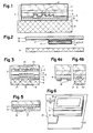
Figur 1 einen Querschnitt durch einen auf ein Substrat geklebten Schichtverbund,Figur 2 den ausgestanzten Schichtverbund als Marke auf einem Träger,Figur 3 den Schichtverbund nachFigur 1 mit Inhomogenitäten in einer Zwischenschicht und in einer Kleberschicht,- Figur 4a den Schichtverbund nach
Figur 1 mit Trenninseln auf der Kleberschicht vor dem Aufkleben, - Figur 4b den Schichtverbund nach Figur 4a nach dem Aufkleben,
Figur 5 eine Anordnung der Trenninseln zwischen einer zweiten Lackschicht und der Kleberschicht sowieFigur 6 einen mittels der Marke gesicherten Ausweis.
- FIG. 1 shows a cross section through a layer composite bonded to a substrate,
- FIG. 2 shows the punched-out layer composite as a mark on a carrier,
- 3 shows the layer composite according to FIG. 1 with inhomogeneities in an intermediate layer and in an adhesive layer,
- FIG. 4a shows the layer composite according to FIG. 1 with separating islands on the adhesive layer before sticking on,
- FIG. 4b shows the layer composite according to FIG. 4a after gluing,
- Figure 5 shows an arrangement of the separation islands between a second lacquer layer and the adhesive layer and
- 6 shows an identity card secured by means of the mark.
In der Figur 1 bedeutet 1 eine Stabilisationsschicht, auf der in der angegebenen Reihenfolge eine Zwischenschicht 2, eine erste Lackschicht 3, eine reflektierende Reflexionsschicht 4, eine zweite Lackschicht 5 und eine Kleberschicht 6 aufgebracht sind. Die Schichten 1 bis 6 bilden einen Schichtverbund 7. Zwischen den Lackschichten 3 und 5 sind optische Beugungsstrukturen 8 eingebettet, z. B. Gitter, Hologramme, Kinegramme usw.. Mit der Kleberschicht 6 wird der Schichtverbund 7 auf einem Substrat 9 befestigt.In FIG. 1, 1 means a stabilization layer, on which an
Die Beugungstrukturen 8 werden durch die Stabilisationsschicht 1, die Zwischenschicht 2 und die Lackschicht 3 hindurch beleuchtet. Das gebeugte und reflektierte Licht wird durch die Schichten 1 bis 3 hindurch zum Betrachter zurückgeworfen.The
Die Stabilisationsschicht 1 besteht mit Vorteil aus einer warmfesten, klaren Folie von hoher optischer Qualität. Verwendbar ist die Folie sowohl in einer farblosen als auch in einer eingefärbten Ausführung. Als Folienmaterial ist beispielsweise Polyester sehr geeignet, das sich neben der hohen optischen Qualität durch eine hohe Zugfestigkeit und eine hohe Temperaturbeständigkeit auszeichnet. Diese Folien sind auf Rollen in verschiedener Dicke handelsüblich, so dass mit Vorteil, wie weiter unten ausgeführt, mittels einer hier nicht gezeigten Umrollanlage auf einer Seite der Stabilisationsschicht 1 der Schichtverbund 7 aufgebaut wird. Vorteilhaft weisen die Folien eine Dicke von 9 bis 30 Mikrometer auf, damit sie einerseits genügend fest sind und andererseits auf dem Substrat 9 nicht zu stark auftragen.The
Als Zwischenschicht 2 ist ein Haftvermittler (Primer) ganzflächig auf der Stabilisationsschicht 1 aufgebracht. Der Haftvermittler bewirkt ein hohes Haftvermögen zwischen der Stabilisationsschicht 1 und der nachfolgenden Lackschicht 3. Als Haftvermittler dient vorteilhaft ein Lack auf der Basis von Poly urethan, damit die Zwischenschicht 2 gegen Licht, vorallem gegen ultraviolettes Licht, und gegen Lösungsmittel beständig ist. Die Zwischenschicht 2 weist eine Auftragsdicke im Mikrometerbereich auf, vorzugsweise 0,8 bis 2 Mikrometer. Vorteilhaft sind für die Stabilisationsschicht 1 auch Folien verwendbar, die bereits beim Lieferant mit der Zwischenschicht 2 überzogen wurden.An adhesion promoter (primer) is applied over the entire surface of the
Die Lackschicht 3 kann auch direkt auf die Stabilisationsschicht 1 aufgetragen sein, falls das Haftvermögen der Lackschicht 3 auf der Folie genügt. Vorteilhaft kann das Haftvermögen mittels einer Vorbehandlung der Stabilisationsschicht 1, z. B. in einer Korona- oder Plasmaentladung, erhöht werden. Eine Grenzschicht zwischen der Lackschicht 3 und der Stabilisationsschicht 1 bzw. eine durch die Vorbehandlung veränderte Oberflächenschicht der Folie übernimmt in diesen Beispielen die Funktion der Zwischenschicht 2.The
Die erste Lackschicht 3 ist vorteilhaft in mindestens einem Arbeitsgang aufgetragen und weist eine Schichtdicke zwischen 0,5 und 1,0 Mikrometer, vorzugsweise 0,6 Mikrometer, auf.The
Anschliessend wird die Reflexionschicht 4 auf die Lackschicht 3 aufgebracht, die mit Vorteil mittels einer Koronaentladung vorbehandelt ist, um eine gute Haftung der Reflexionsschicht 4 auf der Lackschicht 3 zu bewirken. Vorzugsweise ist als Reflexionsschicht 4 ein Metall aufgedampft, beispielsweise Aluminium, das kostengünstig ist und sichtbares sowie infrarotes Licht schon in dünnen Schichten gut reflektiert. Für eine metallische Reflexionsschicht 4 reicht eine Dicke von weniger als 30 Nanometern aus; bei Aluminium beträgt sie etwa 15 Nanometer.The
Vorteilhaft eignet sich auch ein Dielektrikum als Reflexionsschicht 4, mit einer Brechzahl die möglicht stark von den benachbarten Schichten 3 und 5 abweicht, da die Beugungsstrukturen 8 teilweise transparent sind und darunter liegende Materialien, z. B. ein Bild, nicht vollständig verdecken.A dielectric is also advantageously suitable as the
Mit einem der oben erwähnten Prägeverfahren ist das Reliefprofil wenigstens einer optischen Beugungsstruktur 8 mit einer geheizten Matrize durch die Reflexionsschicht 4 hindurch in die Lackschicht 3 eingeprägt. Quer zur Laufrichtung des Folienbandes erfolgt vorteilhaft das Einprägen einer vorbestimmten Anzahl von Beugungsstrukturen 8 gleichzeitig.With one of the embossing processes mentioned above, the relief profile at least one
Es ist auch möglich, die Beugungsstruktur 8 direkt in die Lackschicht 3 einzuprägen, bevor die Reflexionsschicht 4 aufgebracht ist.It is also possible to emboss the
Das Relief der Beugungsstrukturen 8 weist eine typische Profilhöhe von etwa 0,5 Mikrometer auf. Ein Auftrag der zweiten Lackschicht 5 von etwa 0,15 bis 1,5 Mikrometer Dicke (z. B. 1 Mikrometer) ebnet das Relief völlig ein. Mit Vorteil wird für beide Lackschichten 3 und 5 das gleiche thermoplastische Material verwendet, beispielsweise ein Acrylpolymerlack.The relief of the
Der Acrylpolymerlack wird so ausgewählt, dass die vom Prägen in der Lackschicht 3 verbliebenen mechanischen Spannungen bei einer Erwärmung im Bereich von 150° bis 160°C die in der Lackschicht 3 eingeprägten Beugungsstrukturen 8 zerstören.The acrylic polymer lacquer is selected such that the mechanical stresses remaining in the
Der Acrylpolymerlack der Lackschicht 3 kann so eingefärbt werden, dass sie wenigstens in einem vorbestimmten Teil des Lichtspektrums transparent ist. Die Beugungsstruktur 8 bleibt in einer vorbestimmten Farbe maschinell oder visuell auslesbar. Ist beispielsweise der Farbstoff nur für infrarotes Licht durchlässig, ist die Beugungsstruktur 8 dem unbewaffneten Auge verborgen und nur mittels eines hier nicht gezeigten Lesegerätes erkennbar, das die Anwesenheit der Beugungsstruktur 8 festzustellen vermag.The acrylic polymer lacquer of the
Die abschliessend aufgebrachte Kleberschicht 6 von typisch weniger als 6 Mikrometer Dicke ermöglicht das Aufkleben des Schichtverbundes 7 auf das Substrat 9. Die Schichtdicke der Kleberschicht 6 ist vorteilhaft der Oberflächenbeschaffenheit des Substrates 9 angepasst. Bei glatten Substraten 9, wie z. B. bei Photopapieren, reichen 3 Mikrometer Dicke der Kleberschicht 6 aus, während die Kleberschicht 6 bei einem rauhen Substrat 9 mit Vorteil eine Dicke von 6 Mikrometer oder mehr aufweist. Bei einem Papier mit einer normalen Oberflächenstruktur beispielsweise beträgt die Dicke der Kleberschicht 6 etwa 5 Mikrometer.The finally applied
Für die Kleberschicht 6 eignen sich mit Wärme aktivierbare Heisskleber, z. B. auf der Basis von Polymethylmethacrylat, die beim Erwärmen ab etwa 110°C ihre Klebkraft entwickeln. Der Schichtverbund 7 kann erst bei einer Temperatur des Heissklebers von mehr als 170°C vom Substrat 9 gelöst werden, ohne dass im Schichtverbund 7 zu grosse, die Schichten 3 bis 5 zerstörende Zugkräfte auftreten.Suitable for the
Beim Aufkleben wird die Kleberschicht 6 durch die Stabilisationsschicht 1 erwärmt, wobei die Stabilisationsschicht 1 die zugeführte Wärme verteilt und sie gleichmässig den Schichten 3 bis 6 zuführt. In der Kleberschicht 6 sind Temperaturen bis zu 140°C erreichbar, ohne dass die Beugungsstruktur 8 Schaden nimmt. Die auf diese Temperaturen abgestimmten Heisskleber der Kleberschicht 6 verbinden sich innig mit dem Substrat 9 und weisen nach dem Erkalten eine so grosse Haftkraft auf, dass z. B. bei einem Ablöseversuch das papierene Substrat 9 beschädigt wird. Ein Ablösen des Schichtverbundes 7 bei 170°C ist nutzlos, da trotz der Stabilisationsschicht 1 die eingeprägten Beugungsstrukturen 8 in den Lackschichten 3, 5 schon bei Temperaturen zwischen 150 und 160°C thermisch irreversibel zerstört werden. Liegen die Temperaturen beim Ablöseversuch etwas unterhalb von 170°C, zerstören die Zugkräfte die weichen Schichten 3 bis 5.When gluing, the
Der fertiggestellte Schichtverbund 7 verlässt die Umrollanlage beispielsweise in Form einer Rolle, die graphische Kompositionen aus Beugungsstrukturen 8 aufweist.The
Eine Teilfläche, die z. B. eine in sich abgeschlossene vorbestimmte Komposition aus den Beugungsstrukturen 8 enthält, wird vorteilhaft aus dem Schichtverbund 7 als eine Marke 10 (Figur 2) ausgestanzt oder ausgeschnitten. Die Marke 10 wird auf dem Substrat 9 angeordnet. Ein hier nicht gezeigter, heizbarer Stempel erwärmt die Kleberschicht 6 durch die Schichten 1 bis 5 hindurch, bis die Kleberschicht 6 erweicht und sich mit dem Substrat 9 verklebt. Nach dem Erstarren des Heissklebers ist die Marke 10 fest mit dem Substrat 9 verbunden.A partial area, the z. B. contains a self-contained predetermined composition of the
Beispielsweise weist die Marke 10 eine Kreisform von 2 cm Durchmesser auf und ist typisch 25 Mikrometer dick.For example, the
Die Marken 10 können auch in anderen Grössen ausgeschnitten werden sowie ovale, rechteckige oder andere Formen der Berandung aufweisen. Ihre Form und ihre Abmessungen sind z. B. durch die graphische Komposition der Beugungsstrukturen 8 (Figur 1) vorbestimmt.The
Als Substrate 9 eignen sich beispielsweise Papiere oder Kunststoffe mit unterschiedlicher Oberflächenbeschaffenheit, wie sie bei Photopapieren, Ausweisen, Dokumenten, Wertpapieren, Banknoten usw. auftritt.
Gegenüber dem Stand der Technik weist der Schichtverbund 7 (Figur 1) zusätzlich die Stabilisationsschicht 1 und die Zwischenschicht 2 auf, die mit den Schichten 3 bis 6 ausgeschnitten und auf das Substrat 9 übertragen werden. Diese beiden Schichten 1, 2 weisen den Vorteil auf, dass beim Aufkleben das Auftreten von überhitzten Stellen, in denen die Temperatur mehr als 150°C beträgt, in den Schichten 3 bis 5 vermieden wird, in denen örtlich eine thermische Zerstörung der Beugungsstruktur 8 möglich wäre. Die Stabilisationsschicht 1 ist wärmebeständig genug, um die bei etwa 140°C sehr empfindlichen Schichten 3 bis 5 mechanisch zu stützen, damit die beim Kleben unvermeidlich auftretenden mechanischen Druck- bzw. Scherkräfte die Beugungsstruktur 8 nicht zerstören. Erst die Stabilisationsschicht 1 ermöglicht das Aufkleben der Marke 10 mit einem vorteilhaft abgestimmten Heisskleber bei einer Temperatur, die sehr nahe, aber unterhalb der Zerstörungstemperatur der Beugungsstruktur 8 von 150°C bis 160°C liegt, während das Ablösen vom Substrat 9 erst bei einer deutlich höheren Temperatur möglich ist. Infolge der hohen Zugfestigkeit der Stabilisationsschicht 1 und der zusätzlichen Wirkung der Zwischenschicht 2 werden bei tieferen Temperaturen die bei einem Ablöseversuch angewendeten Zugkräfte in die Schichten 3 bis 6 übertragen. Die Zugkräfte zerstören die Beugungsstrukturen 8 mechanisch. Ein Ablöseversuch mit chemischen Lösungsmitteln für den Heisskleber der Kleberschicht 6 ist auch erfolglos, da diese auch die Lackschichten 3 und 5 zerstören.Compared to the prior art, the layer composite 7 (FIG. 1) additionally has the
Vorteilhaft verhindert die Stabilisationsschicht 1 auch eine mechanische Beschädigung der Beugungsstruktur 8 während des Gebrauchs des mittels der Marke 10 (Figur 2) gesicherten Substrates 9.The
In einer Ausführung des Schichtverbunds 7 (Figur 1) weist die Stabilisationsschicht 1 auf der von der Zwischenschicht 2 abgewandten Seite vorteilhaft eine Kaltkleberschicht 11 (Figur 2) auf, damit die Marken 10 nach dem Ausstanzen in einer vorbestimmten Ordnung und Orientierung nur unter Anwendung von Druck auf einen Träger 12 klebbar sind, beispielsweise auf ein silikonisiertes Papier oder auf eine mit Silikon beschichtete klare Polyesterfolie. Diese Polyesterfolie weist den Vorteil auf, dass die Marken 10 durch den Träger 12 hindurch sichtbar sind und sie daher vor dem Aufkleben genau auf dem Substrat 9 angeordnet werden können. Der z. B. zu einer Rolle aufgewickelte Träger 12 mit den Marken 10 ist leicht zu einer hier nicht gezeigten Aufklebemaschine transportierbar. Jede Marke 10 wird einzeln durch den Träger 12 hindurch auf die Klebetemperatur erwärmt und auf das Substrat 9 aufgeklebt. Dabei verändert sich die Kaltkleberschicht 11 nicht, so dass der silikonsierte Träger 12 leicht von der Marke 10 getrennt werden kann.In one embodiment of the layer composite 7 (FIG. 1), the
Beispielsweise kann die Marke 10 vom Träger 12 abgezogen werden und mit der Kaltkleberschicht 11 auf der Heisskleberseite einer klaren Laminierfolie geklebt werden, wie sie zum Heisslaminieren von Bucheinbänden und Ausweisen aller Art verwendet werden. Die Kaltkleberschicht 11 fixiert die Marke 10, bis die Laminierfolie und die Marke 10 gleichzeitig unter der Anwendung von Wärme mit dem Substrat 9 verbunden sind. Vorteilhaft verhindert auch beim Heisslaminieren die Stabilisationsschicht 1 die thermische Zerstörung der Beugungsstrukturen 8, die dies bei Marken 10 nach dem Stand der Technik beobachtet wird.For example, the
Mit Vorteil ist der ganze bandförmige Schichtverbund 7 (Figur 1) mit der Kaltkleberschicht 11 (Figur 2) direkt auf den bandförmigen Träger 12 geklebt. Eine hier nicht gezeigte Einrichtung stanzt die Marken 10 aus dem Schichtverbund 7 frei, ohne den Träger 12 zu verletzen. Der nicht benötigte Teil des Schichtverbundes 7, der keine Marken 10 mehr enthält, wird z. B. vom Träger 12 abgezogen. Bis zur Weiterverarbeitung kann mit Vorteil der mit den Marken 10 beklebte Träger 12 als Rolle gelagert werden.The entire band-shaped layer composite 7 (FIG. 1) with the cold adhesive layer 11 (FIG. 2) is advantageously bonded directly to the band-shaped
Die Kaltkleberschicht 11 weist eine Dicke im Bereich von 5 bis 30 Mikrometer auf. Als Kaltkleber eignen sich solche, die in dieser Dicke praktisch farblos sind und das Betrachten der Beugungsstruktur 8 nicht stören.The cold
Vorteilhaft ist der Träger 12 die klare Laminierfolie selbst, die eine durchsichtige Heisskleberschicht 13 aufweist. Die Marken 10 sind auf der Heisskleberschicht 13 mit der Kaltkleberschicht 11 aufgeklebt. Da durch die klare Laminierfolie die Marke 10 sichtbar ist, ist unmittelbar vor dem Aufkleben eine genaue Positionierung der Marke 10 auf dem Substrat 9 möglich. Die klare Laminierfolie und die Marke 10 werden in der üblichen Art mit etwa 120 bis 140°C auf das Substrat 9 laminiert, wobei sich die Heisskleberschicht 13 und die Kleberschicht 6 mit dem Substrat 9 verbinden. Nach dem Aufkleben ist die Heisskleberschicht 13 glasklar und beeinträchtigt daher das Betrachten der Beugungsstrukturen 8 (Figur 1) nicht.The
Die Laminierfolie und die Heisskleberschicht 13 können eingefärbt sein und als Farbfilter wirken oder vorteilhaft auch farblos, um das auffällige Spiel der Beugungsfarben nicht zu beeinträchtigen. Wegen seiner hohen Zugfestigkeit und seiner Temperaturbeständigkeit eignet sich vorteilhaft Polyester als Material für die Laminierfolie, deren Dicke etwa 80 bis 300 Mikrometer beträgt. Die Heisskleberschicht 13 weist eine Dicke von 80 bis 300 Mikrometer auf und besteht beispielsweise aus Polypropylen.The laminating film and the hot-melt adhesive layer 13 can be colored and act as a color filter, or advantageously also colorless, in order not to impair the conspicuous play of the diffraction colors. Because of its high tensile strength and temperature resistance, polyester is advantageous as Material for the laminating film, the thickness of which is approximately 80 to 300 micrometers. The hot-melt adhesive layer 13 has a thickness of 80 to 300 micrometers and consists, for example, of polypropylene.
In einer anderen Ausführung des Schichtverbunds 7 ist der Haftvermittler in der Zwischenschicht 2 (Figur 3) nicht vollflächig aufgetragen, sondern nur in Haftzonen 14. Die Haftzonen 14 bilden ein vorbestimmtes Muster auf der Stabilisationsschicht 1. Zwischenzonen 15 mit einer geringen Haftfähigkeit trennen die Haftzonen 14 voneinander. Die Zwischenschicht 2 weist nur in den Haftzonen 14 ein hohes Haftvermögen zwischen der Stabilisationsschicht 1 und der nachfolgenden Lackschicht 3 auf.In another embodiment of the
Die Zwischenzonen 15 sind vorteilhaft mit einem Trennmittel ausgefüllt, um einen guten optischen Kontakt zwischen der Stabilisationsschicht 1 und der Lackschicht 3 zu erzielen. Der Haftvermittler und das Trennmittel weisen etwa gleiche Auftragshöhen auf. Das Trennmittel verhindert in den Zwischenzonen 15 ein Haften der Stabilisationsschicht 1 auf der Lackschicht 3.The
Weist die Zwischenschicht 2 ein örtlich variables Haftvermögen auf, wird beim Versuch, den Schichtverbund 7 vom Substrat 9 abzulösen, die Ablösekraft nur in den Haftzonen 14 auf die darunterliegenden Schichten 3 bis 6 übertragen. Dabei treten unterhalb der Haftzonen 14 in den Lackschichten 3 und 5 so grosse Zugkräfte auf, dass die Lackschichten 3 und 5 sowie die Reflexionsschicht 4 örtlich reissen oder überdehnt werden, wobei entweder die Beugungstrukturen 8 auf mechanischem Wege zerstört werden oder sich wenigstens als Folge der örtlichen Dehnung in auffälliger Weise irreversibel verändern. Bei einem papierenen Substrat 9 ist unterhalb der Haftzonen 14 das Herausreissen einer obersten Schicht aus der Oberfläche des Substrates 9 beim Ablöseversuch denkbar.If the
In einer anderen Ausführung des Schichtverbunds 7 weist die Kleberschicht 6 eine örtlich sich ändernde Haftfestigkeit auf. Sobald bei einem Ablöseversuch der Schichtverbund 7 auf Zug beansprucht wird, treten in den Schichten 3 bis 5 örtlich stark variierende Zugkräfte auf, wobei die Schichten 3 bis 5 mechanisch verändert oder zerstört werden. Die örtlich sich ändernde Haftfestigkeit der Kleberschicht 6 wird beispielsweise durch eines der nachstehend beschriebenen Verfahren erreicht.In another embodiment of the
Der Schichtverbund 7 weist ein vorbestimmtes Muster von Trenninseln 16 auf der Kleberschicht 6 (Figur 4a) auf, wobei die Auftragshöhe des in einem zusätzlichen Arbeitsgang aufgetragenen Trennmittels in den Trenninseln 16 weniger als 1 Mikrometer beträgt. Während des Aufklebens sinken die Trenninseln 16 in die heisse, weiche Kleberschicht 6 ein. Die eingesunkenen Trenninseln 16′ (Figur 4b) verhindern örtlich den Kontakt des Heissklebers mit dem Substrat 9. Teilflächen zwischen den eingesunkenen Trenninseln 16′ bilden Haftbrücken 17, in denen der Heisskleber seine volle Klebkraft entwickelt.The
Das Trennmittel kann auch direkt auf die zweite Lackschicht 5 (Figur 5) im Rastermuster der Trenninseln 16 etwa 1 Mikrometer dick aufgetragen werden. Beim anschliessenden vollflächigen Aufbringen der Kleberschicht 6 werden die Trenninseln 16 überdeckt und die Haftbrücken 17 zwischen den Trenninseln 16 ausgefüllt. Nur in den Haftbrücken 17 grenzt die Kleberschicht 6 direkt an die zweite Lackschicht 5 und entwickelt dort ihr volles Haftvermögen zwischen den Schichten 5 und 6.The release agent can also be applied directly to the second lacquer layer 5 (FIG. 5) in the grid pattern of the
In einem dritten Beispiel (Figur 3) ist die Kleberschicht 6 selbst im vorbestimmten Muster auf die zweite Lackschicht 5 aufgetragen. Teilflächen mit einem Heisskleberauftrag bilden die Haftbrücken 17, die von den kleberlosen Teilflächen, den Trenninseln 16, begrenzt sind.In a third example (FIG. 3), the
Als Trennmittel eignen sich z. B. wachsartige Substanzen, Silikone, schlecht haftende Lacke usw..As a release agent z. B. waxy substances, silicones, poorly adhering paints, etc.
Der Vorteil dieser Ausführungen mit einer örtlich sich änderndenden Haftfestigkeit der Zwischenschicht 2 oder der Kleber schicht 6 ist eine zusätzliche Sicherheit gegen ein böswilliges Ablösen der Beugungsstruktur 8 vom geschützten Substrat 9, da die beim Ablöseversuch auftretenden Zugkräfte sich entsprechend dem Muster ungleichmässig ändern und Zerstörungen der Beugungsstrukturen 8 an vorbestimmten Stellen verursachen. Auch eine Kombination der obigen Ausführungen ist vorteilhaft, wenn sich sowohl in der Zwischenschicht 2 als auch in der Kleberschicht 6 das Haftvermögen örtlich ändert, da das Reissen der Schichten 3 bis 5 lässt sich durch das örtliche Haftvermögen in den beiden Schichten 2 und 6 sehr genau vorbestimmen.The advantage of these designs with a locally changing adhesive strength of the
Beispielsweise sind bei der Marke 10 (Figur 6) die Zwischenschicht 2 und die Kleberschicht 6 nur in einer Randzone 18 vollflächig aufgetragen, damit die Randzone 18 der Stabilisationsschicht 1 fest mit dem Substrat 9 verbunden ist und keine Angriffsmöglichkeiten zum Ablösen der Marke 10 bietet.For example, in the case of the mark 10 (FIG. 6), the
In einem von der Randzone 18 umschlossenen Gebiet 19 bilden die Zonen 14 (Figur 3) und 15 einerseits sowie die Trenninseln 16 und die Haftbrücken 17 andererseits ein vorbestimmtes Muster, wobei in der Kleberschicht 6 die Trenninseln 16 im Bereich der Haftzonen 14 und die Haftbrücken 17 im Bereich der Zwischenzonen 15 angeordnet sind. Beim Ablöseversuch reissen die Lackschichten 3 und 5 längs den Grenzen zwischen den Haftzonen 14 und den Zwischenzonen 15, da die Lackschichten 3 und 5 in den Haftzonen 14 stärker an der Stabilisationsschicht 1 als am Substrat 9 haften, während sie im Bereich der Zwischenzonen 15 fest mit dem Substrat 9 verbunden sind, jedoch sich leicht von der Stabilisationsschicht 1 lösen. Auf dem Dokument bleiben daher Reste des Schichtverbundes 7 im Bereich der Haftbrücken 17 zurück.In an
Weist das Muster der Zwischenschicht 2 als Haftzonen 14 Umrisse von Zeichen oder von Buchstaben auf, die beispielsweise ein Wort darstellen, weist die abgelöste Marke 10 ein gut sichtbares Mal auf, das irreversibel auf einen Fälschungsversuch hinweist. Auf dem Substrat 9 bleibt das durch die Haftbrücken 17 vorbestimmte Negativ des Musters zurück.If the pattern of the
Insbesondere eignet sich die Marke 10 (Figur 6) vorteilhaft zum Sichern einer in einen Ausweis 20 eingeklebten Photographie 21 z. B. des Inhabers. Anstelle eines leicht fälschbaren Aufdrucks des Amtsstempels oder einer Prägung des Amtssiegels ist die Marke 10 über benachbarte Teilflächen des Ausweises 20 und der Photographie 21 angeordnet. Die eine Teilfläche der Kleberschicht 6 ist mit der Photographie 21 und die andere Teilfläche mit dem Substrat 9 des Ausweises 20 fest verbunden. Vorteilhaft erfolgt diese Verbindung unter Anwendung von Wärme während des Auflaminierens der als Träger 12 dienenden klaren Laminierfolie, die z. B. den ganzen Ausweis abdeckt.In particular, the mark 10 (FIG. 6) is advantageously suitable for securing a
Claims (11)
Applications Claiming Priority (2)
| Application Number | Priority Date | Filing Date | Title |
|---|---|---|---|
| CH2110/89 | 1989-06-05 | ||
| CH211089 | 1989-06-05 |
Publications (2)
| Publication Number | Publication Date |
|---|---|
| EP0401466A1 true EP0401466A1 (en) | 1990-12-12 |
| EP0401466B1 EP0401466B1 (en) | 1995-06-21 |
Family
ID=4226109
Family Applications (1)
| Application Number | Title | Priority Date | Filing Date |
|---|---|---|---|
| EP90102997A Expired - Lifetime EP0401466B1 (en) | 1989-06-05 | 1990-02-16 | Laminate with diffraction structures |
Country Status (14)
| Country | Link |
|---|---|
| US (1) | US5104471A (en) |
| EP (1) | EP0401466B1 (en) |
| JP (1) | JP2934281B2 (en) |
| AT (1) | ATE124153T1 (en) |
| CA (1) | CA2015750C (en) |
| DE (1) | DE59009271D1 (en) |
| DK (1) | DK0401466T3 (en) |
| ES (1) | ES2073465T3 (en) |
| FI (1) | FI902766A0 (en) |
| LT (1) | LT3327B (en) |
| LV (1) | LV10219B (en) |
| PT (1) | PT94248B (en) |
| RU (1) | RU2041028C1 (en) |
| UA (1) | UA26399A (en) |
Cited By (21)
| Publication number | Priority date | Publication date | Assignee | Title |
|---|---|---|---|---|
| EP0498040A1 (en) * | 1991-02-08 | 1992-08-12 | Landis & Gyr Technology Innovation AG | Method of manufacturing documents with security marks |
| GB2259049A (en) * | 1991-08-12 | 1993-03-03 | Landis & Gyr Betriebs Ag | Identification card with machine-readable optically encoded information in diffraction structures |
| US5207855A (en) * | 1989-12-21 | 1993-05-04 | Landis & Gyr Betriebs Ag | Apparatus for sticking on stamps from an embossing foil |
| EP0660262A2 (en) * | 1993-12-27 | 1995-06-28 | Toppan Printing Co., Ltd. | Transparent hologram seal |
| FR2719918A1 (en) * | 1994-05-11 | 1995-11-17 | Hologram Ind Sarl | Method for irreversible transfer of a diffraction grating. Transfer film and device for implementing the process. |
| EP0718795A1 (en) | 1994-12-22 | 1996-06-26 | Landis & Gyr Technology Innovation AG | Optically machine readable data carrier |
| US5629093A (en) * | 1994-07-08 | 1997-05-13 | Minnesota Mining And Manufacturing Company | Transparent multilayer film and its use for protection of data on documents as well as a tamper-proof label |
| EP0741370B1 (en) * | 1995-05-05 | 1998-08-19 | Landis & Gyr Technology Innovation AG | Method for applying a security element on a substrate |
| EP0883085A1 (en) * | 1997-06-06 | 1998-12-09 | Electrowatt Technology Innovation AG | Diffractive surface pattern |
| US6324004B1 (en) | 1999-01-21 | 2001-11-27 | Ovd Kingegram Ag | Planar patterns with superimposed diffraction gratings |
| US6417968B1 (en) | 1998-01-27 | 2002-07-09 | René Staub | Diffractive surface pattern |
| DE10139653A1 (en) * | 2001-08-11 | 2003-02-20 | Tesa Ag | Label with increased protection against counterfeiting |
| WO2003033274A1 (en) | 2001-10-12 | 2003-04-24 | Ovd Kinegram Ag | Security element |
| FR2849708A1 (en) * | 2003-01-03 | 2004-07-09 | Banque De France | WAVEGUIDE SAFETY DEVICE |
| FR2898208A1 (en) * | 2006-03-02 | 2007-09-07 | Novatec Sa | Bottle e.g. white wine bottle, container e.g. cheese container, package e.g. blister type package, or object traceability providing method for e.g. wine field, involves using two types of secured labels in upstream and downstream cycles |
| EP1897700A2 (en) * | 2006-09-08 | 2008-03-12 | De La Rue International Limited | Method of manufacturing a security device |
| EP2234091A1 (en) | 2009-03-27 | 2010-09-29 | Hueck Folien Ges.m.b.H. | Safety element, in particular safety label with manipulation verification |
| US9321294B2 (en) | 2012-01-23 | 2016-04-26 | Leonhard Kurz Stiftung & Co. Kg | Security document and method for producing a security document |
| EP3640040A1 (en) * | 2018-10-19 | 2020-04-22 | Surys | Safety film and method for manufacturing a safety film |
| EP3738784B1 (en) | 2018-01-09 | 2021-10-06 | Toppan Printing Co., Ltd. | Laminate, certificate, and method of manufacturing laminate |
| WO2023208666A1 (en) * | 2022-04-25 | 2023-11-02 | Ovd Kinegram Ag | Laminate and method for producing a laminate |
Families Citing this family (32)
| Publication number | Priority date | Publication date | Assignee | Title |
|---|---|---|---|---|
| NL8902949A (en) * | 1989-11-29 | 1991-06-17 | Leer Koninklijke Emballage | METHOD FOR MANUFACTURING A MATERIAL WITH INTERFERENCE PATTERN LIKE HOLOGRAPHIC IMAGES |
| GB9106128D0 (en) * | 1991-03-22 | 1991-05-08 | Amblehurst Ltd | Article |
| ATE131115T1 (en) * | 1991-10-14 | 1995-12-15 | Landis & Gyr Tech Innovat | SAFETY ELEMENT. |
| US5538753A (en) * | 1991-10-14 | 1996-07-23 | Landis & Gyr Betriebs Ag | Security element |
| DE4211235C2 (en) * | 1992-04-03 | 2003-04-17 | Gao Ges Automation Org | Method and device for producing metallic surface elements on substrates and their use |
| US5318816A (en) * | 1992-12-23 | 1994-06-07 | Hughes Aircraft Company | Laminated hologram decals for identification cards and the like |
| KR100362350B1 (en) * | 1994-03-16 | 2003-02-19 | 오브이디 키네그람 악티엔게젤샤프트 | Optical carrier with optical label |
| US5591527A (en) * | 1994-11-02 | 1997-01-07 | Minnesota Mining And Manufacturing Company | Optical security articles and methods for making same |
| US5510171A (en) * | 1995-01-19 | 1996-04-23 | Minnesota Mining And Manufacturing Company | Durable security laminate with hologram |
| US20040007315A1 (en) * | 1995-06-07 | 2004-01-15 | Weder Donald E. | Process for producing holographic material |
| US6372073B1 (en) * | 1999-08-11 | 2002-04-16 | Southpac Trust International Inc. | Process for producing holographic material |
| LT4281B (en) | 1996-03-15 | 1998-01-26 | Fizikinės Elektronikos Institutas | Layered product comprising diffraction structure |
| US6334248B1 (en) | 1996-09-20 | 2002-01-01 | Total Register, Inc. | Apparatus and method for the continuous high speed rotary application of stamping foil |
| US5946781A (en) * | 1997-05-09 | 1999-09-07 | Kuo; Weiwu A. | Multi-layer packaging foil and method for manufacturing the foil |
| LT4319B (en) | 1997-07-03 | 1998-03-25 | Fizikinės Elektronikos Institutas | A method for making of identifiables symbols |
| US6149204A (en) * | 1998-08-10 | 2000-11-21 | Moore U.S.A. Inc. | Registration-decal form with protective patch |
| US6185041B1 (en) | 1998-10-23 | 2001-02-06 | Duke University | Projection lens and system |
| DE19924750C2 (en) * | 1999-04-08 | 2002-11-14 | Ovd Kinegram Ag Zug | Reading arrangement for information strips with optically coded information |
| US6761959B1 (en) * | 1999-07-08 | 2004-07-13 | Flex Products, Inc. | Diffractive surfaces with color shifting backgrounds |
| US20030029083A1 (en) * | 1999-08-11 | 2003-02-13 | Weder Donald E. | Wrapper having a holographic image thereon |
| DE10007916A1 (en) * | 2000-02-21 | 2001-08-23 | Giesecke & Devrient Gmbh | Multilayer laminated card with interposed security element having relief structures |
| DE10127981C1 (en) * | 2001-06-08 | 2003-01-16 | Ovd Kinegram Ag Zug | Diffractive security element |
| DE50212483D1 (en) * | 2001-10-19 | 2008-08-21 | Leonhard Kurz Stiftung & Co Kg | PRAGUE AND SAFETY DOCUMENT |
| JP2003302514A (en) * | 2002-04-09 | 2003-10-24 | Ricoh Co Ltd | Diffraction optical element, method for manufacturing the same, optical pickup device and optical disk drive device |
| US20040126669A1 (en) * | 2002-08-15 | 2004-07-01 | Ruschmann Henry W. | Method for producing holographic iridescent film |
| US7745065B2 (en) | 2005-06-02 | 2010-06-29 | Dai Nippon Printing Co., Ltd. | Volume hologram transfer foil, and volume hologram multilayer structure |
| FR2897556B1 (en) | 2006-02-23 | 2008-05-23 | Fasver Soc Par Actions Simplif | TRANSFER FILM OF AT LEAST ONE BRAND ON AT LEAST ONE SUBSTRATE TO BE SECURED, METHOD OF MANUFACTURING AND TRANSFERRING SUCH A TRANSFER FILM |
| DE102006016139A1 (en) * | 2006-04-06 | 2007-10-18 | Ovd Kinegram Ag | Multi-layer body with volume hologram |
| JP2008083599A (en) * | 2006-09-28 | 2008-04-10 | Toppan Printing Co Ltd | Optical element and display body using the same |
| BRPI0818641A2 (en) * | 2007-10-05 | 2015-04-07 | Upm Raflatac Oy | Label and label use |
| EP2109084A1 (en) * | 2008-04-11 | 2009-10-14 | HID Global GmbH | A method of checking the authenticity of a document with a co-laminated fabric layer inside |
| US10457018B2 (en) * | 2010-11-15 | 2019-10-29 | Illinois Tool Works Inc. | Decorative and/or secure element for homogeneous card construction |
Citations (3)
| Publication number | Priority date | Publication date | Assignee | Title |
|---|---|---|---|---|
| EP0012375A2 (en) * | 1978-12-14 | 1980-06-25 | Hoechst Aktiengesellschaft | Identification card |
| EP0271673A1 (en) * | 1986-11-13 | 1988-06-22 | LGZ LANDIS & GYR ZUG AG | Multi-layer document |
| EP0201323B1 (en) * | 1985-05-07 | 1994-08-17 | Dai Nippon Insatsu Kabushiki Kaisha | Article incorporating a transparent hologramm |
Family Cites Families (12)
| Publication number | Priority date | Publication date | Assignee | Title |
|---|---|---|---|---|
| US595664A (en) | 1897-12-14 | Fishing-float | ||
| US661683A (en) | 1899-06-20 | 1900-11-13 | Sullivan Machinery Co | Rock-drill cylinder-head. |
| GB170832A (en) | 1920-10-26 | 1922-04-06 | Hans Christian Hansen | An improved pouring spout or funnel |
| BE334286A (en) | 1925-06-02 | |||
| US4057919A (en) * | 1974-04-02 | 1977-11-15 | G.A.O. Gesellschaft Fur Automation Und Organisation Mbh | Laminated data carrier protected against forgery, particularly identification card |
| CH595664A5 (en) * | 1975-11-17 | 1978-02-15 | Landis & Gyr Ag | |
| US4184700A (en) * | 1975-11-17 | 1980-01-22 | Lgz Landis & Gyr Zug Ag | Documents embossed with optical markings representing genuineness information |
| SU594936A1 (en) | 1976-07-14 | 1978-02-28 | Опытное Проектно-Конструкторское Бюро Алтайского Научно-Исследовательского Института Земледелия И Селекции Сельскохозяйственных Культур | Sheep-shearing plant |
| JPS5988780A (en) * | 1982-11-08 | 1984-05-22 | アメリカン・バンク・ノ−ト・カムパニ− | Making of optical refraction recording body and optical refraction pattern |
| CH661683A5 (en) * | 1983-09-19 | 1987-08-14 | Landis & Gyr Ag | DEVICE FOR MAINTAINING HIGH-RESOLUTION RELIEF PATTERNS. |
| DE3422908C2 (en) * | 1984-06-20 | 1986-04-30 | Leonhard Kurz GmbH & Co, 8510 Fürth | Embossing foil, in particular hot stamping foil, with a surface that can be written on |
| DE3527412A1 (en) * | 1985-07-31 | 1987-02-12 | Kurz Leonhard Fa | MULTI-LAYER FILM, ESPECIALLY HOT-IMPRESSION FILM AND METHOD FOR THE PRODUCTION THEREOF |
-
1990
- 1990-02-16 DE DE59009271T patent/DE59009271D1/en not_active Expired - Fee Related
- 1990-02-16 AT AT90102997T patent/ATE124153T1/en not_active IP Right Cessation
- 1990-02-16 EP EP90102997A patent/EP0401466B1/en not_active Expired - Lifetime
- 1990-02-16 ES ES90102997T patent/ES2073465T3/en not_active Expired - Lifetime
- 1990-02-16 DK DK90102997.5T patent/DK0401466T3/en not_active Application Discontinuation
- 1990-04-30 CA CA002015750A patent/CA2015750C/en not_active Expired - Lifetime
- 1990-05-24 JP JP2132785A patent/JP2934281B2/en not_active Expired - Fee Related
- 1990-06-04 PT PT94248A patent/PT94248B/en not_active IP Right Cessation
- 1990-06-04 FI FI902766A patent/FI902766A0/en not_active Application Discontinuation
- 1990-06-04 RU SU904830026A patent/RU2041028C1/en not_active IP Right Cessation
- 1990-06-04 UA UA4830026A patent/UA26399A/en unknown
- 1990-11-27 US US07/618,707 patent/US5104471A/en not_active Expired - Lifetime
-
1992
- 1992-11-10 LV LVP-92-191A patent/LV10219B/en unknown
- 1992-12-02 LT LTIP232A patent/LT3327B/en not_active IP Right Cessation
Patent Citations (3)
| Publication number | Priority date | Publication date | Assignee | Title |
|---|---|---|---|---|
| EP0012375A2 (en) * | 1978-12-14 | 1980-06-25 | Hoechst Aktiengesellschaft | Identification card |
| EP0201323B1 (en) * | 1985-05-07 | 1994-08-17 | Dai Nippon Insatsu Kabushiki Kaisha | Article incorporating a transparent hologramm |
| EP0271673A1 (en) * | 1986-11-13 | 1988-06-22 | LGZ LANDIS & GYR ZUG AG | Multi-layer document |
Cited By (36)
| Publication number | Priority date | Publication date | Assignee | Title |
|---|---|---|---|---|
| US5207855A (en) * | 1989-12-21 | 1993-05-04 | Landis & Gyr Betriebs Ag | Apparatus for sticking on stamps from an embossing foil |
| EP0498040A1 (en) * | 1991-02-08 | 1992-08-12 | Landis & Gyr Technology Innovation AG | Method of manufacturing documents with security marks |
| GB2259049B (en) * | 1991-08-12 | 1995-09-27 | Landis & Gyr Betriebs Ag | Identification card production. |
| GB2259049A (en) * | 1991-08-12 | 1993-03-03 | Landis & Gyr Betriebs Ag | Identification card with machine-readable optically encoded information in diffraction structures |
| BE1005510A3 (en) * | 1991-08-12 | 1993-08-31 | Landis & Gyr Betr S A G | Identification card and method of making such identification cards. |
| EP0660262A3 (en) * | 1993-12-27 | 1996-06-05 | Toppan Printing Co Ltd | Transparent hologram seal. |
| USRE38321E1 (en) | 1993-12-27 | 2003-11-18 | Toppan Printing Co., Ltd. | Transparent hologram seal |
| EP0660262A2 (en) * | 1993-12-27 | 1995-06-28 | Toppan Printing Co., Ltd. | Transparent hologram seal |
| WO1995031756A1 (en) * | 1994-05-11 | 1995-11-23 | Hologram Industries S.A.R.L. | Method for irreversibly transferring a diffraction grating, transfer film and device therefor |
| FR2719918A1 (en) * | 1994-05-11 | 1995-11-17 | Hologram Ind Sarl | Method for irreversible transfer of a diffraction grating. Transfer film and device for implementing the process. |
| US5629093A (en) * | 1994-07-08 | 1997-05-13 | Minnesota Mining And Manufacturing Company | Transparent multilayer film and its use for protection of data on documents as well as a tamper-proof label |
| EP0718795A1 (en) | 1994-12-22 | 1996-06-26 | Landis & Gyr Technology Innovation AG | Optically machine readable data carrier |
| US5882463A (en) * | 1995-05-05 | 1999-03-16 | Landis & Gyr Technology Innovation Ag | Method of applying a security element to a substrate |
| EP0741370B1 (en) * | 1995-05-05 | 1998-08-19 | Landis & Gyr Technology Innovation AG | Method for applying a security element on a substrate |
| EP0883085A1 (en) * | 1997-06-06 | 1998-12-09 | Electrowatt Technology Innovation AG | Diffractive surface pattern |
| WO1998055964A1 (en) * | 1997-06-06 | 1998-12-10 | Electrowatt Technology Innovation Ag | Diffractive surface pattern |
| US6417968B1 (en) | 1998-01-27 | 2002-07-09 | René Staub | Diffractive surface pattern |
| US6324004B1 (en) | 1999-01-21 | 2001-11-27 | Ovd Kingegram Ag | Planar patterns with superimposed diffraction gratings |
| DE10139653A1 (en) * | 2001-08-11 | 2003-02-20 | Tesa Ag | Label with increased protection against counterfeiting |
| WO2003033274A1 (en) | 2001-10-12 | 2003-04-24 | Ovd Kinegram Ag | Security element |
| US7145723B2 (en) | 2001-10-12 | 2006-12-05 | Ovd Kinegram Ag | Security element |
| FR2849708A1 (en) * | 2003-01-03 | 2004-07-09 | Banque De France | WAVEGUIDE SAFETY DEVICE |
| WO2004062942A1 (en) * | 2003-01-03 | 2004-07-29 | Banque De France | Waveguide safety device |
| FR2898208A1 (en) * | 2006-03-02 | 2007-09-07 | Novatec Sa | Bottle e.g. white wine bottle, container e.g. cheese container, package e.g. blister type package, or object traceability providing method for e.g. wine field, involves using two types of secured labels in upstream and downstream cycles |
| EP1897700A2 (en) * | 2006-09-08 | 2008-03-12 | De La Rue International Limited | Method of manufacturing a security device |
| EP1897700A3 (en) * | 2006-09-08 | 2008-06-11 | De La Rue International Limited | Method of manufacturing a security device |
| RU2533665C2 (en) * | 2009-03-27 | 2014-11-20 | Хуек Фолиен Гез.М.Б.Х. | Security element, particularly security tag with indication of tempering |
| WO2010108567A1 (en) * | 2009-03-27 | 2010-09-30 | Hueck Folien Ges.M.B.H. | Security element, particularly security element having evidence of manipulation |
| EP2234091A1 (en) | 2009-03-27 | 2010-09-29 | Hueck Folien Ges.m.b.H. | Safety element, in particular safety label with manipulation verification |
| EP2234091B1 (en) | 2009-03-27 | 2015-03-25 | Hueck Folien Ges.m.b.H. | Safety element, in particular safety label with manipulation verification |
| US9321294B2 (en) | 2012-01-23 | 2016-04-26 | Leonhard Kurz Stiftung & Co. Kg | Security document and method for producing a security document |
| DE102012001121C5 (en) * | 2012-01-23 | 2018-01-04 | Leonhard Kurz Stiftung & Co. Kg | Security document, method for producing a security document and method for producing an individualized security document |
| EP3738784B1 (en) | 2018-01-09 | 2021-10-06 | Toppan Printing Co., Ltd. | Laminate, certificate, and method of manufacturing laminate |
| EP3640040A1 (en) * | 2018-10-19 | 2020-04-22 | Surys | Safety film and method for manufacturing a safety film |
| FR3087385A1 (en) * | 2018-10-19 | 2020-04-24 | Surys | SECURITY FILM AND SECURE DOCUMENT USING SECURITY FILM |
| WO2023208666A1 (en) * | 2022-04-25 | 2023-11-02 | Ovd Kinegram Ag | Laminate and method for producing a laminate |
Also Published As
| Publication number | Publication date |
|---|---|
| LT3327B (en) | 1995-06-26 |
| DK0401466T3 (en) | 1995-10-30 |
| ES2073465T3 (en) | 1995-08-16 |
| ATE124153T1 (en) | 1995-07-15 |
| US5104471A (en) | 1992-04-14 |
| LV10219B (en) | 1995-04-20 |
| RU2041028C1 (en) | 1995-08-09 |
| DE59009271D1 (en) | 1995-07-27 |
| EP0401466B1 (en) | 1995-06-21 |
| PT94248B (en) | 1996-12-31 |
| JP2934281B2 (en) | 1999-08-16 |
| PT94248A (en) | 1991-04-18 |
| CA2015750A1 (en) | 1990-12-05 |
| CA2015750C (en) | 1999-11-02 |
| LV10219A (en) | 1994-10-20 |
| UA26399A (en) | 1999-08-30 |
| JPH0323932A (en) | 1991-01-31 |
| LTIP232A (en) | 1994-10-25 |
| FI902766A0 (en) | 1990-06-04 |
Similar Documents
| Publication | Publication Date | Title |
|---|---|---|
| EP0401466B1 (en) | Laminate with diffraction structures | |
| EP0741370B2 (en) | Method for applying a security element on a substrate | |
| EP0537439B2 (en) | Security element | |
| EP1940618B1 (en) | Method for transferring a multilayer body and a transfer film | |
| DE10013410B4 (en) | Laminate, in particular in the form of cards, and process for its production | |
| EP2344342B1 (en) | Card having embedded security element | |
| RU2359837C2 (en) | Protected document and/or valuable security | |
| DE102005017169B4 (en) | transfer film | |
| EP0466118B1 (en) | Multilayered optically variable element | |
| DE4334848C1 (en) | Security with window | |
| DE69534274T2 (en) | METHOD AND APPARATUS FOR IRREVERSIBLE TRANSMISSION OF A LOAD GRID | |
| WO2012164011A1 (en) | Multi-layer body, method for producing it, and production of forgery-proof documents using said multi-layer body | |
| DE4130896A1 (en) | Adhesive laminate with diffraction pattern | |
| DE102007005416B4 (en) | Embossing foil and thus formed safety sticker | |
| DE69901886T3 (en) | PROCESS FOR PRODUCING A SAFETY OBJECT | |
| EP0626909A1 (en) | Transfer method and device | |
| DE102012223700A1 (en) | Method for producing a security feature for a value and / or security product and value and / or security product (pixelated application element) | |
| EP3894232A1 (en) | Method for producing a film intermediate product, film intermediate product and method for producing a product | |
| DE4314579A1 (en) | Self adhesive label for display in road vehicle | |
| DE112004002006B4 (en) | Security element and process for its manufacture | |
| DE102008019871B3 (en) | Method for the production of multilayered security document, comprises subjecting a photopolymer foil on a first side of a carrier material and connecting the foil with the carrier material | |
| EP1050484B1 (en) | Tear strip with security feature, production method and its use in packaging material | |
| EP3271191B1 (en) | Security element | |
| DE102020005769A1 (en) | Security element transfer material for register-accurate transfer of security elements on documents of value | |
| OA20537A (en) | Method for creating security element on security documents, security document containing security element, and hot stamping foil for security document. |
Legal Events
| Date | Code | Title | Description |
|---|---|---|---|
| PUAI | Public reference made under article 153(3) epc to a published international application that has entered the european phase |
Free format text: ORIGINAL CODE: 0009012 |
|
| AK | Designated contracting states |
Kind code of ref document: A1 Designated state(s): AT BE CH DE DK ES GB LI NL SE |
|
| 17P | Request for examination filed |
Effective date: 19910131 |
|
| RAP1 | Party data changed (applicant data changed or rights of an application transferred) |
Owner name: LANDIS & GYR BUSINESS SUPPORT AG |
|
| TCNL | Nl: translation of patent claims filed | ||
| 17Q | First examination report despatched |
Effective date: 19930929 |
|
| RAP1 | Party data changed (applicant data changed or rights of an application transferred) |
Owner name: LANDIS & GYR TECHNOLOGY INNOVATION AG |
|
| GRAA | (expected) grant |
Free format text: ORIGINAL CODE: 0009210 |
|
| AK | Designated contracting states |
Kind code of ref document: B1 Designated state(s): AT BE CH DE DK ES GB LI NL SE |
|
| REF | Corresponds to: |
Ref document number: 124153 Country of ref document: AT Date of ref document: 19950715 Kind code of ref document: T |
|
| GBT | Gb: translation of ep patent filed (gb section 77(6)(a)/1977) |
Effective date: 19950628 |
|
| REF | Corresponds to: |
Ref document number: 59009271 Country of ref document: DE Date of ref document: 19950727 |
|
| REG | Reference to a national code |
Ref country code: ES Ref legal event code: FG2A Ref document number: 2073465 Country of ref document: ES Kind code of ref document: T3 |
|
| REG | Reference to a national code |
Ref country code: DK Ref legal event code: T3 |
|
| PGFP | Annual fee paid to national office [announced via postgrant information from national office to epo] |
Ref country code: AT Payment date: 19960202 Year of fee payment: 7 Ref country code: BE Payment date: 19960202 Year of fee payment: 7 Ref country code: DK Payment date: 19960202 Year of fee payment: 7 Ref country code: NL Payment date: 19960202 Year of fee payment: 7 Ref country code: SE Payment date: 19960202 Year of fee payment: 7 |
|
| PGFP | Annual fee paid to national office [announced via postgrant information from national office to epo] |
Ref country code: ES Payment date: 19960212 Year of fee payment: 7 |
|
| PLBE | No opposition filed within time limit |
Free format text: ORIGINAL CODE: 0009261 |
|
| STAA | Information on the status of an ep patent application or granted ep patent |
Free format text: STATUS: NO OPPOSITION FILED WITHIN TIME LIMIT |
|
| 26N | No opposition filed | ||
| PG25 | Lapsed in a contracting state [announced via postgrant information from national office to epo] |
Ref country code: DK Effective date: 19970216 Ref country code: AT Effective date: 19970216 |
|
| REG | Reference to a national code |
Ref country code: DK Ref legal event code: EBP |
|
| PG25 | Lapsed in a contracting state [announced via postgrant information from national office to epo] |
Ref country code: ES Free format text: LAPSE BECAUSE OF NON-PAYMENT OF DUE FEES Effective date: 19970217 Ref country code: SE Effective date: 19970217 |
|
| PG25 | Lapsed in a contracting state [announced via postgrant information from national office to epo] |
Ref country code: BE Effective date: 19970228 |
|
| BERE | Be: lapsed |
Owner name: LANDIS & GYR TECHNOLOGY INNOVATION A.G. Effective date: 19970228 |
|
| PG25 | Lapsed in a contracting state [announced via postgrant information from national office to epo] |
Ref country code: NL Effective date: 19970901 |
|
| EUG | Se: european patent has lapsed |
Ref document number: 90102997.5 |
|
| NLV4 | Nl: lapsed or anulled due to non-payment of the annual fee |
Effective date: 19970901 |
|
| REG | Reference to a national code |
Ref country code: ES Ref legal event code: FD2A Effective date: 19990301 |
|
| REG | Reference to a national code |
Ref country code: CH Ref legal event code: PUE Owner name: ELECTROWATT TECHNOLOGY INNOVATION AG TRANSFER- OVD Ref country code: CH Ref legal event code: PFA Free format text: LANDIS & GYR TECHNOLOGY INNOVATION AG TRANSFER- ELECTROWATT TECHNOLOGY INNOVATION AG Ref country code: CH Ref legal event code: NV Representative=s name: ELECTROWATT TECHNOLOGY INNOVATION AG C-IPR, 4470 |
|
| REG | Reference to a national code |
Ref country code: CH Ref legal event code: NV Representative=s name: PATENTANWALTSBUERO DR. URS FALK |
|
| REG | Reference to a national code |
Ref country code: GB Ref legal event code: 732E |
|
| REG | Reference to a national code |
Ref country code: GB Ref legal event code: IF02 |
|
| PGFP | Annual fee paid to national office [announced via postgrant information from national office to epo] |
Ref country code: CH Payment date: 20080225 Year of fee payment: 19 |
|
| PGFP | Annual fee paid to national office [announced via postgrant information from national office to epo] |
Ref country code: DE Payment date: 20071217 Year of fee payment: 19 |
|
| PGFP | Annual fee paid to national office [announced via postgrant information from national office to epo] |
Ref country code: GB Payment date: 20090223 Year of fee payment: 20 |
|
| REG | Reference to a national code |
Ref country code: CH Ref legal event code: PL |
|
| PG25 | Lapsed in a contracting state [announced via postgrant information from national office to epo] |
Ref country code: LI Free format text: LAPSE BECAUSE OF NON-PAYMENT OF DUE FEES Effective date: 20090228 Ref country code: CH Free format text: LAPSE BECAUSE OF NON-PAYMENT OF DUE FEES Effective date: 20090228 |
|
| PG25 | Lapsed in a contracting state [announced via postgrant information from national office to epo] |
Ref country code: DE Free format text: LAPSE BECAUSE OF NON-PAYMENT OF DUE FEES Effective date: 20090901 |
|
| REG | Reference to a national code |
Ref country code: GB Ref legal event code: PE20 Expiry date: 20100215 |
|
| PG25 | Lapsed in a contracting state [announced via postgrant information from national office to epo] |
Ref country code: GB Free format text: LAPSE BECAUSE OF EXPIRATION OF PROTECTION Effective date: 20100215 |