EP0342947A2 - Implantable patient-activated fluid delivery device with bolus injection port - Google Patents
Implantable patient-activated fluid delivery device with bolus injection port Download PDFInfo
- Publication number
- EP0342947A2 EP0342947A2 EP89304969A EP89304969A EP0342947A2 EP 0342947 A2 EP0342947 A2 EP 0342947A2 EP 89304969 A EP89304969 A EP 89304969A EP 89304969 A EP89304969 A EP 89304969A EP 0342947 A2 EP0342947 A2 EP 0342947A2
- Authority
- EP
- European Patent Office
- Prior art keywords
- casing
- passage
- membrane
- chamber
- bolus injection
- Prior art date
- Legal status (The legal status is an assumption and is not a legal conclusion. Google has not performed a legal analysis and makes no representation as to the accuracy of the status listed.)
- Withdrawn
Links
Images
Classifications
-
- A—HUMAN NECESSITIES
- A61—MEDICAL OR VETERINARY SCIENCE; HYGIENE
- A61M—DEVICES FOR INTRODUCING MEDIA INTO, OR ONTO, THE BODY; DEVICES FOR TRANSDUCING BODY MEDIA OR FOR TAKING MEDIA FROM THE BODY; DEVICES FOR PRODUCING OR ENDING SLEEP OR STUPOR
- A61M5/00—Devices for bringing media into the body in a subcutaneous, intra-vascular or intramuscular way; Accessories therefor, e.g. filling or cleaning devices, arm-rests
- A61M5/14—Infusion devices, e.g. infusing by gravity; Blood infusion; Accessories therefor
- A61M5/142—Pressure infusion, e.g. using pumps
- A61M5/14244—Pressure infusion, e.g. using pumps adapted to be carried by the patient, e.g. portable on the body
- A61M5/14276—Pressure infusion, e.g. using pumps adapted to be carried by the patient, e.g. portable on the body specially adapted for implantation
- A61M5/1428—Pressure infusion, e.g. using pumps adapted to be carried by the patient, e.g. portable on the body specially adapted for implantation with manual pumping action
Definitions
- Implantable devices have been disclosed in the prior art that may be activated by ambulatory patients when the administration of measured doses of therapeutic agents is required.
- cancer patients suffering from terminal lower torso cancer may require routine injections of morphine, either epidurally or intrathecally, and, upon receiving such injections, are sufficiently relieved of the symptoms of pain to move about and perform many routine and normal functions.
- Other chronic ailments also require frequent dosages of therapeutic agents in the treatment of chronic conditions, such as insulin in the case of diabetes.
- Implantable devices capable of delivering measured amounts of medicament on demand are disclosed in United States patents 4,634,427, 4,548,607, 4,588,394, 4,557,722, 4,544,371, and 4,543,088.
- the fluid delivery device of this invention is formed of soft and deformable (preferably elastomeric) material capable of being worn comfortably and effectively in implanted condition over an extended period.
- the device has a relatively rigid internal structure that serves to support various operative elements, such support also performing the functions of distributing pumping forces produced by finger pressure and protecting the casing (as well as interior elements) against damage and possible leakage during refilling operations.
- top wall has a central target zone that may be easily located by touch (even when the device is implanted) and that serves as both the pump-actuating site against which finger pressure is exerted when drug delivery is needed and as the site for medicament injection when refilling of the reservoir is required.
- fluid pressure equalization within the device insures that pump activation and drug delivery do not occur unless directed and localized force is applied specifically to the target zone -- a force that can be expected to be applied only intentionally.
- the target zone for actuating and refilling the device is centrally disposed in an enlarged portion of the casing of generally circular outline when viewed in plan.
- a reduced integral portion of the same casing provides a bolus injection site spaced laterally from the main site for pump activation and reservoir replenishment. Because of the reduced dimensions of the casing portion that provides the bolus injection site, and because of the generally distinctive configuration of the casing as a whole, a physician or nurse, through tactile inspection, may easily determine the location of the bolus injection site of an implanted device and, by injecting into that site, supply a dose of selected medicament (which may be the same agent, or a different agent, than the one contained in the device's reservoir) to the patient.
- selected medicament which may be the same agent, or a different agent, than the one contained in the device's reservoir
- the bolus injection site is self-sealing and is constructed so that intermixing of the injected agent with the fluid in the reservoir of the device is prevented. Such prevention occurs not only because of protective barriers that limit needle penetration but also because of secondary functions performed by the check valve system of the device. In addition, because of the lateral relationship between the bolus injection site and the combination filling/pump-acivating site, a unitary implantable device of relatively low profile is provided.
- the implantable fluid delivery device includes a casing formed of soft, deformable polymeric material, preferably elastomeric material, having top and bottom walls defining a fluid reservoir therebetween.
- a rigid support plate is disposed within the casing and devides the reservoir into upper and lower chambers that communicate with each other through an opening in the plate.
- Compressible pumping means is mounted upon the plate within the upper chamber and includes a deformable pump housing that defines a pump cavity with a first passage connecting that cavity with the lower chamber of the reservoir.
- a second passage connects the same cavity with the outlet port of the device, and check valves are positioned to control flow through the respective passages.
- the top wall of the casing includes a flexible pump-actuating zone.
- Connecting means in the form of a self-sealing septum combined with a rigid cover plate operatively connect the top wall's pump actuating zone with the pump housing.
- the self-sealing properties of the piercable septum are enhanced by a construction that maintains that septum in a partially-compressed state.
- the casing and many of the components contained within it are readily deformable, being formed of silicone rubber or other suitable material, and although build up of fluid pressure due to unexpected compressive loads on the device is possible, pressure equalization within the reservoir, on opposite sides of elements such as the deformable pump housing and the check valve for the second passage, insure that deformation of the casing will not result in fluid delivery unless such deformation specifically includes depression of the target zone of the top wall in the direction of the compressible pump.
- a porous metal filter is mounted upon the support plate at the entry to the first passage leading from the reservoir to the pump cavity.
- the filter also performs a rate controlling function and therefore prevents surges of fluid, produced by compressive deformation of the device's deformable casing, that might otherwise cause damage to the pump assembly.
- Channel-defining ribs within the reservoir also function to equalize pressure within that reservoir and prevent obstructive contact with the rigid filter that might block fluid flow to the pump cavity.
- the bolus injection site also includes a self-sealing septum or membrane maintained in a compressed state and associated with a rigid metal filter, similar to the first filter, that limits needle penetration and throttles the rate of fluid flow at the bolus injection site.
- the numeral 10 generally designates an implantable delivery device having a casing 11 formed of soft, deformable polymeric material. While various materials having such properties might be used, an elastomeric material such as silicone rubber has been found particularly effective because of its deformability, recoverability, durability, and biocompatability.
- the casing includes preformed (molded) upper and lower walls 12 and 13 that are sealed together along a horizontal midline 14.
- the upper wall 12 may be formed in two or more sections that allow the prefabrication of subassemblies.
- upper wall 12 includes main section 12a, central section 12b and inner section 12c. The central and inner sections together define an upper chamber 15, whereas the bottom wall defines a lower chamber 16. The two chambers communicate and together define an enlarged reservoir 17.
- a relatively rigid support plate 18 is interposed between the upper and lower chambers of the reservoir and, as shown most clearly in Figures 3 and 7, extends substantially the full width and length of the casing.
- the plate is sandwiched between the upper and lower walls 12 and 13 and, if desired, may be provided with an outer layer 18a of silicone rubber or other suitable material to enhance biocompatability and facilitate adhesive attachment of the parts.
- the core 18b of the support plate may be formed of any tough and rigid material, including metallic and ceramic materials, although a polymeric material such as polycarbonate is believed particularly suitable.
- Opening 19 through the support plate 18 places the upper and lower chambers 15, 16 of the reservoir in communication with each other. In use of the device, at least the lower chamber of the reservoir would contain a liquid medicament to be discharged in metered amounts upon actuation of the device; however, for clarity of illustration such fluid is not depicted in the drawings.
- the pumping means for the device is located in the upper chamber 15 of the reservoir and is supported upon plate 18.
- the pumping means includes a dome-shaped pump housing 20 formed of silicone rubber or other suitable elastomeric material.
- the rim 21 of the pump housing is secured within an annular channel 22 provided in the upper surface of inner wall section 12c, and a downwardly-projecting stem portion 23 of that wall section projects through an opening 24 in the rigid support plate.
- Inlet flow passage 25 extends through the stem portion 23 and places the pump chamber or cavity 26 in communication with the lower chamber 16 of the reservoir.
- An annular valve seat 27 is provided at the upper end of passage 25 and is normally engaged by a dish-shaped elastomeric membrane valve member 28 that has its circular outer peripheral portion secured to wall section 12c.
- the membrane valve member 27 may be formed of silicone rubber. As shown most clearly in Figures 4-6, the valve member is provided with openings 29 therethrough that are located outboard of valve seat 27 and that therefore allow flow of fluid between passage 25 and pump chamber 26 only when the valve member 28 is urged away from valve seat 27.
- a rigid filter member or disc 30 Directly below the pump, and mounted along the underside of the support plate 18, is a rigid filter member or disc 30.
- the disc may be formed of sintered metal or a fine metallic mesh and is secured in place by an annular rim 31 adhesively bonded to the underside of the support plate 10 about the entrance to inlet passage 25.
- the surface of the bottom wall of the casing is provided with parallel ribs 13a that prevent the bottom wall from blocking fluid flow from lower chamber 16 into filter 30 and inlet passage 25 should the bottom wall be flexed upwardly into contact with the filter (Figure 7).
- a second passage 32 also communicates with the chamber 26 of the pump and leads radially away from the pump through the inner section 12c of the top wall.
- the second passage 32 is parallel and in close proximity to rigid support plate 18 and communicates at its opposite end with a valve opening 33 defined by an annular flexible lip 34 that is preferably formed integrally with section 12c of the top wall.
- the lip defines a valve seat and the opening 33 is normally closed by a cup-shaped elastomeric valve member 35 mounted within cylindrical chamber 36. In its normal undeformed state, valve member 35 engages lip 34 to maintain the valve in closed condition; however, as shown in Figure 5, the valve member is capable of being deformed upwardly into unseated condition to allow fluid flow from secondary passage 32 and opening 33 into chamber 36 and then into outlet passage 37.
- the outlet passage leads to outlet port 38 which in turn communicates with the lumen of a catheter 39.
- a tapered ferrule or connector 40 is secured to the casing 11 and supports the catheter at its point of exit from the casing.
- filter disc 30 and the core 18b of support plate 18 are composed of soft, deformable material. Silicone rubber of the same formulation or different formulations may be used for all of such resilient elements which, as already indicated, are secured together by any suitable adhesive to provide the assembly illustrated in the drawings.
- the dome-shaped pump housing 20 has an upstanding stem portion 41 that is anchored to a rigid disc 43 formed of polycarbonate or any other suitable material having sufficient strength, hardness, and rigidity to resist needle penetration.
- the disc 43 is formed in two sections 43a and 43b to facilitate assembly, or subassembly, with pump housing 20; however, it is to be understood that if desired the rigid disc 43 may instead be formed in one piece.
- the disc 43 is surrounded by an annular plate 44 that is also formed of rigid material, preferably the same material as disc 43.
- the periphery of the annular plate is locked in place between the central section 12b and the inner section 12c of upper wall 12.
- the opposing edges or side surfaces of the disc 43 and annular plate 44 are spaced apart to provide flow passages 45 that maintain the portions of the upper chamber above and below the disc and annular plate in pressure-equalizing flow relation.
- a rim 46 of the disc 43 projects outwardly and is engagable with the annular plate 44 to limit the extent of upward movement of the disc and, if desired, the rim may be serrated or discontinuous to insure that passages 45 remain open at all times.
- an inverted cup-shaped septum 47 having an apertured side wall 48 and, when fully assembled, a planar end wall 49.
- the lower periphery of the side wall 48 is secured within an annular channel provided in rigid disc 43.
- the septum is formed of an elastomer such as silicone rubber and is secured to the underside of the central section 12b of the casing's top wall 12 by means of an adhesive attachment layer 50.
- end wall 49 of the elastomeric septum is spaced well above disc 43 to define a medicament-receiving chamber 51.
- the end wall in an untensioned state is dome shaped.
- the convex end wall 49 curves upwardly and inwardly so that when flattened and adhesively secured to the planar undersurface of the casing's top wall section 12b, the end wall 49 will have its upper surface portion in a compressed state and will be maintained in that compressed state by adhesive layer or pad 50. It has been found that such limited compression of the upper stratum of end wall 49 greatly enhances the self-sealing properties of the septum upon withdrawal of an injection needle.
- the upper surface of the central section 12b of casing's top wall 12 is provided with an indentation 54 of circular outline.
- the indentation identifies the target site for both pump actuation and fluid injection and helps a user locate such site by touch even when the fluid delivery device is implanted.
- the needle 55 of a syringe is simply inserted into the casing through the indented zone of the top wall until the tip of the needle engages rigid disc 43 within medicament-receiving chamber 51 ( Figure 4). Discharge of fluid from the syringe flows outwardly through openings 56 in the side wall of septum 47.
- An aliquot of fluid substantially equal to the volume of pump chamber or cavity 26 (when the pump housing is undeformed) is therefore discharged into the outlet passage 37 and through outlet port 38.
- the top wall returns to its original position largely because of the recovery forces exerted by the dome-shaped pump housing 20 and the flexible top wall portion 12b.
- casing 11 is of distinctive configuration, being of flattened pear shape with an enlarged body portion 70 and a reduced lateral portion 71.
- the target zone defined by depression 54 is generally centrally located in that portion of the casing's upper wall 12 that covers body portion 70, and a port 72, similar in appearance to depression 54, is provided in the upper wall portion that covers the casing's reduced lateral portion 71.
- Port 72 defines the target zone for a bolus injection site.
- a user may by tactile investigation readily distinguish the two portions of the casing and locate injection port 72 when the direct injection of a bolus of medicament is indicated.
- the laterally-spaced relation between the two sites contributes to the low profile of the device and, because of the substantial spacing between those sites, a user may readily distinguish one from the other and direct a needle of a syringe into the intended target zone.
- the bolus injection port subassembly includes a rigid, cylindrical, open-ended, sleeve 73 mounted in a recess 74 formed in top wall 12 of the casing ( Figure 10).
- sleeve 73 is advantageously formed of polycarbonate, although any of a variety of other materials having similar properties may be used.
- the frusto-conical surface defining port 72 in addition to defining the target zone for bolus injection, provides a hard and smooth deflecting surface for directing a needle into the cylindrical body or sleeve.
- a rigid filter 76 is secured within sleeve 73 at its lower end and, as shown in the drawings, is spaced directly above outlet passage 37.
- the filter may be formed of any suitable rigid, porous material and may be identical in composition and construction to the metal filter disc 30 at the entrance to inlet passage 25.
- a membrane 77 formed of silicone rubber or other suitable elastomeric material is mounted within sleeve 73 at the upper end thereof, directly below frusto-concial surface 72.
- a spacer ring 78 disposed between filter 76 and membrane 77 completes the subassembly and maintains the membrane and filter in spaced relation with a bolus receiving chamber 79 disposed therebetween.
- the membrane 77 is of generally cylindrical shape when undeformed and uncompressed but, when mounted in sleeve 73, the membrane is in a state of radial compression that causes a slight upward and downward bowing or bulging of its upper and lower surfaces ( Figure 10). Such radial compression enhances the self-sealing properties of the membrane following withdrawal of an injection needle.
- a syringe needle 75 is inserted through membrane 77 and into chamber 79 with the extent of such insertion being controlled by the rigid protective filter 76.
- Medicament is injected into the chamber and passes through the filter directly into outlet passage 37 leading to outlet port 38 and catheter 39.
- Some backup of fluid may occur, as indicated by the arrows extending to the left in Figure 10.
- the pressure increase within the outlet passage 37 may cause outlet valve 35 to lift from its seat ( Figure 10)
- reverse flow is limited by membrane inlet valve member 28. More specifically, pressure increase within the chamber 26 of pump housing 20 forces the dish-shaped membrane valve member 28 downwardly into even tighter engagement with its valve seat 27, thereby preventing the reverse flow of fluid downwardly through inlet passage 25 and into the lower chamber of the reservoir.
- FIG. 12 and 13 The embodiment depicted in Figures 12 and 13 is identical in construction and operation to the one already described except that a protective grid member 80 is disposed within the inlet passage 25.
- the insert member is provided with a plurality of ribs 81 defining longitudinal flow passages 82 therebetween.
- the insert member When mounted within inlet passage 25, the insert member has its upper end disposed just slightly below valve seat 27. If desired, the lower end of the insert may be braced against rigid inlet filter disc 30 ( Figure 12).
- the thin membrane filter member 28 is therefore protected against substantial deformation and possible rupture should substantial back pressure develop during bolus injection.
- the inlet valve thus performs dual functions. It serves as a check valve during a pumping operation when top wall 12 is depressed in target zone 54 to deliver a metered amount of medicament contained in reservoir 17, and it also functions as a safety valve to limit reverse flow of fluid in the system during bolus injection.
Abstract
An implantable fluid delivery device (10) for dispensing metered amounts of liquid medication when a pump assembly within its casing is operated by finger pressure applied to a central target zone (54) of the casing's top wall. The top wall also includes an injection site (72) spaced from the central target zone (54) for use when a bolus of medicament is to be injected into the device and delivered directly to the patient without passing through the pump assembly. The flattened pear shape of the casing and the location of the sites for pump activation and refilling on one hand, and for bolus injection on the other, facilitate error-free use and operation of the device. Although limited fluid backup may occur during bolus injection, a valve arrangement within the device prevents intermixing of the bolus medicament with the liquid medication in the reservoir. In a second embodiment, a supporting grid (80) prevents possible injury to the backup-restraining valve during bolus injection.
Description
- Various implantable devices have been disclosed in the prior art that may be activated by ambulatory patients when the administration of measured doses of therapeutic agents is required. For example, cancer patients suffering from terminal lower torso cancer may require routine injections of morphine, either epidurally or intrathecally, and, upon receiving such injections, are sufficiently relieved of the symptoms of pain to move about and perform many routine and normal functions. Other chronic ailments also require frequent dosages of therapeutic agents in the treatment of chronic conditions, such as insulin in the case of diabetes. Implantable devices capable of delivering measured amounts of medicament on demand are disclosed in United States patents 4,634,427, 4,548,607, 4,588,394, 4,557,722, 4,544,371, and 4,543,088. Other United States patents of general interest pertaining to implantable pumping or infusing systems are 4,560,375, 4,258,711, 3,769,982, 3,827,439, 4,013,074, 4,265,241, 4,360,019, 4,487,603, 4,496,343, 4,511,355, 4,604,090, and 4,627,832. Reference may also be had to United States Statutory Invention Registration H150.
- Despite the attention that has been directed in recent years to the development of implantable drug delivery systems, prior devices have often been deficient in significant respects. The recognition of such deficiencies is considered to be one of the important aspects of this invention, along with the discovery and development of the means for overcoming those shortcomings. Unlike many of the prior devices, the fluid delivery device of this invention is formed of soft and deformable (preferably elastomeric) material capable of being worn comfortably and effectively in implanted condition over an extended period. In spite of its compliant outer casing, the device has a relatively rigid internal structure that serves to support various operative elements, such support also performing the functions of distributing pumping forces produced by finger pressure and protecting the casing (as well as interior elements) against damage and possible leakage during refilling operations.
- The compactness of the device and its ease of operation result partly from the fact that its top wall has a central target zone that may be easily located by touch (even when the device is implanted) and that serves as both the pump-actuating site against which finger pressure is exerted when drug delivery is needed and as the site for medicament injection when refilling of the reservoir is required. Enhanced self-sealing properties of the top wall and its underlying structure, coupled with a relatively rigid protective shield interposed between the top wall and the pump assembly, helps insure that the device may be easily refilled without risk of internal damage or leakage.
- Even though the soft, resilient casing of the device yields or deforms with body movements and in response to both internally and externally applied forces, fluid pressure equalization within the device insures that pump activation and drug delivery do not occur unless directed and localized force is applied specifically to the target zone -- a force that can be expected to be applied only intentionally.
- The target zone for actuating and refilling the device is centrally disposed in an enlarged portion of the casing of generally circular outline when viewed in plan. A reduced integral portion of the same casing provides a bolus injection site spaced laterally from the main site for pump activation and reservoir replenishment. Because of the reduced dimensions of the casing portion that provides the bolus injection site, and because of the generally distinctive configuration of the casing as a whole, a physician or nurse, through tactile inspection, may easily determine the location of the bolus injection site of an implanted device and, by injecting into that site, supply a dose of selected medicament (which may be the same agent, or a different agent, than the one contained in the device's reservoir) to the patient. The bolus injection site is self-sealing and is constructed so that intermixing of the injected agent with the fluid in the reservoir of the device is prevented. Such prevention occurs not only because of protective barriers that limit needle penetration but also because of secondary functions performed by the check valve system of the device. In addition, because of the lateral relationship between the bolus injection site and the combination filling/pump-acivating site, a unitary implantable device of relatively low profile is provided.
- In brief, the implantable fluid delivery device includes a casing formed of soft, deformable polymeric material, preferably elastomeric material, having top and bottom walls defining a fluid reservoir therebetween. A rigid support plate is disposed within the casing and devides the reservoir into upper and lower chambers that communicate with each other through an opening in the plate. Compressible pumping means is mounted upon the plate within the upper chamber and includes a deformable pump housing that defines a pump cavity with a first passage connecting that cavity with the lower chamber of the reservoir. A second passage connects the same cavity with the outlet port of the device, and check valves are positioned to control flow through the respective passages.
- The top wall of the casing includes a flexible pump-actuating zone. Connecting means in the form of a self-sealing septum combined with a rigid cover plate operatively connect the top wall's pump actuating zone with the pump housing. The self-sealing properties of the piercable septum are enhanced by a construction that maintains that septum in a partially-compressed state. Although the casing and many of the components contained within it are readily deformable, being formed of silicone rubber or other suitable material, and although build up of fluid pressure due to unexpected compressive loads on the device is possible, pressure equalization within the reservoir, on opposite sides of elements such as the deformable pump housing and the check valve for the second passage, insure that deformation of the casing will not result in fluid delivery unless such deformation specifically includes depression of the target zone of the top wall in the direction of the compressible pump.
- A porous metal filter is mounted upon the support plate at the entry to the first passage leading from the reservoir to the pump cavity. In addition to filtering fluid, the filter also performs a rate controlling function and therefore prevents surges of fluid, produced by compressive deformation of the device's deformable casing, that might otherwise cause damage to the pump assembly. Channel-defining ribs within the reservoir also function to equalize pressure within that reservoir and prevent obstructive contact with the rigid filter that might block fluid flow to the pump cavity. The bolus injection site also includes a self-sealing septum or membrane maintained in a compressed state and associated with a rigid metal filter, similar to the first filter, that limits needle penetration and throttles the rate of fluid flow at the bolus injection site.
- Other features, objects, and advantages will become apparent from the specification and drawings.
-
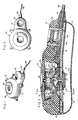
- Figure 1 is a perspective view of an implantable fluid delivery device embodying this invention.
- Figure 2 is a top plan view.
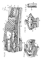
- Figure 3 is an enlarged longitudinal vertical sectional view of the device.
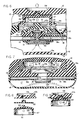
- Figure 4 is a still further enlarged vertical longitudinal sectional view showing the filling port, needle guard, and pump assembly.
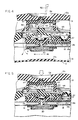
- Figure 5 is a fragmentary sectional view similar to Figure 4 but illustrating the condition of the device during a pumping step.
- Figure 6 is a similar fragmentary sectional view showing the parts during a recovery step in which the pump cavity is being refilled.
- Figure 7 is a transverse sectional view taken along line 7-7 of Figure 3.
- Figure 8 is an exploded sectional view illustrating the deformable septum and associated parts prior to assembly.
- Figure 9 is a sectional view illustrating the parts of Figure 8 in partially assembled condition.
- Figure 10 is an enlarged longitudinal sectional view illustrating the relationship between the bolus injection site, outlet valve, and inlet valve at the time of bolus injection.
- Figure 11 is an enlarged perspective view of the inlet valve member and its valve seat.
- Figure 12 is an enlarged vertical sectional view of a modified construction including a supportive grid for the inlet valve member.
- Figure 13 is a perspective view of the grid insert of the embodiment of Figure 12.
- Referring to the drawings, and particularly to Figures 1-3, the
numeral 10 generally designates an implantable delivery device having a casing 11 formed of soft, deformable polymeric material. While various materials having such properties might be used, an elastomeric material such as silicone rubber has been found particularly effective because of its deformability, recoverability, durability, and biocompatability. Viewed generally, the casing includes preformed (molded) upper andlower walls horizontal midline 14. To facilitate manufacture, theupper wall 12 may be formed in two or more sections that allow the prefabrication of subassemblies. Thus, in the illustration given,upper wall 12 includesmain section 12a,central section 12b andinner section 12c. The central and inner sections together define anupper chamber 15, whereas the bottom wall defines alower chamber 16. The two chambers communicate and together define an enlargedreservoir 17. - A relatively
rigid support plate 18 is interposed between the upper and lower chambers of the reservoir and, as shown most clearly in Figures 3 and 7, extends substantially the full width and length of the casing. The plate is sandwiched between the upper andlower walls outer layer 18a of silicone rubber or other suitable material to enhance biocompatability and facilitate adhesive attachment of the parts. Thecore 18b of the support plate may be formed of any tough and rigid material, including metallic and ceramic materials, although a polymeric material such as polycarbonate is believed particularly suitable. Opening 19 through thesupport plate 18 places the upper andlower chambers - The pumping means for the device is located in the
upper chamber 15 of the reservoir and is supported uponplate 18. The pumping means includes a dome-shaped pump housing 20 formed of silicone rubber or other suitable elastomeric material. Therim 21 of the pump housing is secured within anannular channel 22 provided in the upper surface ofinner wall section 12c, and a downwardly-projectingstem portion 23 of that wall section projects through an opening 24 in the rigid support plate.Inlet flow passage 25 extends through thestem portion 23 and places the pump chamber orcavity 26 in communication with thelower chamber 16 of the reservoir. Anannular valve seat 27 is provided at the upper end ofpassage 25 and is normally engaged by a dish-shaped elastomericmembrane valve member 28 that has its circular outer peripheral portion secured towall section 12c. Like other components of the drug delivery device, themembrane valve member 27 may be formed of silicone rubber. As shown most clearly in Figures 4-6, the valve member is provided withopenings 29 therethrough that are located outboard ofvalve seat 27 and that therefore allow flow of fluid betweenpassage 25 and pumpchamber 26 only when thevalve member 28 is urged away fromvalve seat 27. - Directly below the pump, and mounted along the underside of the
support plate 18, is a rigid filter member ordisc 30. The disc may be formed of sintered metal or a fine metallic mesh and is secured in place by anannular rim 31 adhesively bonded to the underside of thesupport plate 10 about the entrance toinlet passage 25. Directly below thefilter disc 30, the surface of the bottom wall of the casing is provided withparallel ribs 13a that prevent the bottom wall from blocking fluid flow fromlower chamber 16 intofilter 30 andinlet passage 25 should the bottom wall be flexed upwardly into contact with the filter (Figure 7). - A
second passage 32 also communicates with thechamber 26 of the pump and leads radially away from the pump through theinner section 12c of the top wall. Thesecond passage 32 is parallel and in close proximity torigid support plate 18 and communicates at its opposite end with avalve opening 33 defined by an annularflexible lip 34 that is preferably formed integrally withsection 12c of the top wall. The lip defines a valve seat and theopening 33 is normally closed by a cup-shapedelastomeric valve member 35 mounted within cylindrical chamber 36. In its normal undeformed state,valve member 35 engageslip 34 to maintain the valve in closed condition; however, as shown in Figure 5, the valve member is capable of being deformed upwardly into unseated condition to allow fluid flow fromsecondary passage 32 andopening 33 into chamber 36 and then intooutlet passage 37. The outlet passage leads tooutlet port 38 which in turn communicates with the lumen of acatheter 39. A tapered ferrule orconnector 40 is secured to the casing 11 and supports the catheter at its point of exit from the casing. - All of the elements so far described, except for
filter disc 30 and the core 18b ofsupport plate 18, are composed of soft, deformable material. Silicone rubber of the same formulation or different formulations may be used for all of such resilient elements which, as already indicated, are secured together by any suitable adhesive to provide the assembly illustrated in the drawings. - The dome-shaped
pump housing 20 has anupstanding stem portion 41 that is anchored to arigid disc 43 formed of polycarbonate or any other suitable material having sufficient strength, hardness, and rigidity to resist needle penetration. In the illustration given, thedisc 43 is formed in twosections pump housing 20; however, it is to be understood that if desired therigid disc 43 may instead be formed in one piece. - The
disc 43 is surrounded by anannular plate 44 that is also formed of rigid material, preferably the same material asdisc 43. The periphery of the annular plate is locked in place between thecentral section 12b and theinner section 12c ofupper wall 12. As shown in Figures 3 and 4, the opposing edges or side surfaces of thedisc 43 andannular plate 44 are spaced apart to provideflow passages 45 that maintain the portions of the upper chamber above and below the disc and annular plate in pressure-equalizing flow relation. Arim 46 of thedisc 43 projects outwardly and is engagable with theannular plate 44 to limit the extent of upward movement of the disc and, if desired, the rim may be serrated or discontinuous to insure thatpassages 45 remain open at all times. - Above
disc 43 is an inverted cup-shapedseptum 47 having anapertured side wall 48 and, when fully assembled, aplanar end wall 49. The lower periphery of theside wall 48 is secured within an annular channel provided inrigid disc 43. The septum is formed of an elastomer such as silicone rubber and is secured to the underside of thecentral section 12b of the casing'stop wall 12 by means of anadhesive attachment layer 50. - Of particular importance is the fact that
end wall 49 of the elastomeric septum is spaced well abovedisc 43 to define a medicament-receivingchamber 51. Also, while shown in the assembly drawings to be of generally planar configuration (except for locating protuberance 52), the end wall in an untensioned state is dome shaped. As shown in Figure 8, in the absence of distorting forces theconvex end wall 49 curves upwardly and inwardly so that when flattened and adhesively secured to the planar undersurface of the casing'stop wall section 12b, theend wall 49 will have its upper surface portion in a compressed state and will be maintained in that compressed state by adhesive layer orpad 50. It has been found that such limited compression of the upper stratum ofend wall 49 greatly enhances the self-sealing properties of the septum upon withdrawal of an injection needle. - Ideally, the upper surface of the
central section 12b of casing'stop wall 12 is provided with anindentation 54 of circular outline. The indentation identifies the target site for both pump actuation and fluid injection and helps a user locate such site by touch even when the fluid delivery device is implanted. When fluid is to be supplied to the reservoir, theneedle 55 of a syringe is simply inserted into the casing through the indented zone of the top wall until the tip of the needle engagesrigid disc 43 within medicament-receiving chamber 51 (Figure 4). Discharge of fluid from the syringe flows outwardly throughopenings 56 in the side wall ofseptum 47. Since the upper and lower chambers of the reservoir are in communication, such fluid enters the space above the dome-shapedpump housing 20 and aboveoutlet valve member 35, and is free to pass into the lower chamber throughopening 19. Upon removal ofneedle 55, thecompressed end wall 49 of theseptum 47 then closes and reseals the reservoir. - The same target zone, as defined by
indentation 54, is used for finger actuation of the pump mechanism. Depression of thetop wall 12 in the area ofindentation 54, as depicted in Figure 5, drives theseptum 47 andrigid disc 43 downwardly, deformingpump housing 20 and substantiallyexhausting pump cavity 26. Fluid in the pump cavity is driven outwardly intosecond passage 32 with the pressure increase beneathoutlet valve 35 causing the outlet valve to flex upwardly into open position. An aliquot of fluid substantially equal to the volume of pump chamber or cavity 26 (when the pump housing is undeformed) is therefore discharged into theoutlet passage 37 and throughoutlet port 38. When finger pressure is removed, the top wall returns to its original position largely because of the recovery forces exerted by the dome-shapedpump housing 20 and the flexibletop wall portion 12b. As thepump cavity 26 expands, the pressure differential causes themembrane valve member 28 to lift away from itsseat 27, allowing fluid from thelower chamber 16 of the reservoir to enter thepump cavity 26 through thefirst passage 25 andopenings 29 in the membrane (Figure 6). Once the pump cavity is filled and pressure is equalized, theinlet valve member 28 closes and the parts again assume the relationships depicted in Figures 3 and 4. - Since the upper and lower chambers of the reservoir are in open communication at all times, deformations of the resilient casing 11 produced by body movement or other causes do not result in unintentional delivery of medicament to the patient. For example, should patient movement cause compression of the device and subsequent upward flexure of
bottom wall 13 from the position shown in Figure 4, fluid displaced fromlower chamber 16 is free to enter the upper chamber of the reservoir, including the area directly aboveoutlet valve member 35. The outlet valve will therefore remain closed despite the deformation of the casing because pressure will be equal on both sides ofoutlet valve 35. The double-headed arrows in Figure 4 are intended to indicate the reversibility of movement of fluid throughout the upper and lower chambers of the reservoir that results in pressure equalization. - It will be observed from Figures 1 and 2 that casing 11 is of distinctive configuration, being of flattened pear shape with an
enlarged body portion 70 and a reducedlateral portion 71. The target zone defined bydepression 54 is generally centrally located in that portion of the casing'supper wall 12 that coversbody portion 70, and aport 72, similar in appearance todepression 54, is provided in the upper wall portion that covers the casing's reducedlateral portion 71.Port 72 defines the target zone for a bolus injection site. - Since the
lateral portion 71 of the casing is substantially narrower thanbody portion 70 and since the top surface oflateral portion 71 is stepped well below the outer top surface ofbody portion 70, a user may by tactile investigation readily distinguish the two portions of the casing and locateinjection port 72 when the direct injection of a bolus of medicament is indicated. The laterally-spaced relation between the two sites contributes to the low profile of the device and, because of the substantial spacing between those sites, a user may readily distinguish one from the other and direct a needle of a syringe into the intended target zone. - The bolus injection port subassembly includes a rigid, cylindrical, open-ended,
sleeve 73 mounted in arecess 74 formed intop wall 12 of the casing (Figure 10). Like the core of therigid support plate 18,sleeve 73 is advantageously formed of polycarbonate, although any of a variety of other materials having similar properties may be used. The frusto-conicalsurface defining port 72, in addition to defining the target zone for bolus injection, provides a hard and smooth deflecting surface for directing a needle into the cylindrical body or sleeve. Arigid filter 76 is secured withinsleeve 73 at its lower end and, as shown in the drawings, is spaced directly aboveoutlet passage 37. The filter may be formed of any suitable rigid, porous material and may be identical in composition and construction to themetal filter disc 30 at the entrance toinlet passage 25. - A membrane 77 formed of silicone rubber or other suitable elastomeric material is mounted within
sleeve 73 at the upper end thereof, directly below frusto-concial surface 72. Aspacer ring 78 disposed betweenfilter 76 and membrane 77 completes the subassembly and maintains the membrane and filter in spaced relation with abolus receiving chamber 79 disposed therebetween. The membrane 77 is of generally cylindrical shape when undeformed and uncompressed but, when mounted insleeve 73, the membrane is in a state of radial compression that causes a slight upward and downward bowing or bulging of its upper and lower surfaces (Figure 10). Such radial compression enhances the self-sealing properties of the membrane following withdrawal of an injection needle. - Use of the bolus injection site takes advantage of the implanted condition of the
fluid delivery device 10 while at the same time bypasses the pumping mechanism of that device to permit direct delivery of a medicament to theoutlet port 38. As shown in Figure 10, a syringe needle 75 is inserted through membrane 77 and intochamber 79 with the extent of such insertion being controlled by the rigidprotective filter 76. Medicament is injected into the chamber and passes through the filter directly intooutlet passage 37 leading tooutlet port 38 andcatheter 39. Some backup of fluid may occur, as indicated by the arrows extending to the left in Figure 10. While the pressure increase within theoutlet passage 37 may causeoutlet valve 35 to lift from its seat (Figure 10), reverse flow is limited by membraneinlet valve member 28. More specifically, pressure increase within thechamber 26 ofpump housing 20 forces the dish-shapedmembrane valve member 28 downwardly into even tighter engagement with itsvalve seat 27, thereby preventing the reverse flow of fluid downwardly throughinlet passage 25 and into the lower chamber of the reservoir. - The embodiment depicted in Figures 12 and 13 is identical in construction and operation to the one already described except that a
protective grid member 80 is disposed within theinlet passage 25. The insert member is provided with a plurality ofribs 81 defining longitudinal flow passages 82 therebetween. When mounted withininlet passage 25, the insert member has its upper end disposed just slightly belowvalve seat 27. If desired, the lower end of the insert may be braced against rigid inlet filter disc 30 (Figure 12). The thinmembrane filter member 28 is therefore protected against substantial deformation and possible rupture should substantial back pressure develop during bolus injection. The inlet valve thus performs dual functions. It serves as a check valve during a pumping operation whentop wall 12 is depressed intarget zone 54 to deliver a metered amount of medicament contained inreservoir 17, and it also functions as a safety valve to limit reverse flow of fluid in the system during bolus injection. - While in the foregoing, an embodiment of the invention has been disclosed in considerable detail for purposes of illustration, it will be understood by those skilled in the art that many of these details may be varied without departing from the spirit and scope of the invention.
Claims (9)
1. An implantable, finger-pressure-activated device for dispensing metered amounts of fluid to a patient, comprising a casing formed of soft, deformable polymeric material having a top wall and a bottom wall defining a fluid reservoir with an outlet port; pumping means within said casing comprising a compressible pump housing having a pumping chamber; said casing including an enlarged body portion and a reduced lateral portion; said top wall of said body portion having a central target zone for finger pressure activation of said pump when said target zone is depressed; and said reduced lateral portion having a bolus injection chamber communicating with said outlet port; said top wall of said reduced lateral portion having a bolus injection port adjacent said bolus injection chamber with said bolus injection port separated from said chamber by a needle-piercable self-sealing elastomeric membrane.
2. The device of Claim 1 in which said self-sealing membrane is circular in outline and is supported in said casing in a condition of radial compression.
3. The device of Claim 2 in which said membrane is supported in said casing by a generally cylindrical sleeve formed of rigid material capable of resisting needle penetration.
4. The device of Claim 3 in which said sleeve has upper and lower end portions; a rigid porous filter element capable of resisting needle penetration being supported by said sleeve in the lower end portion thereof, said membrane being mounted in said sleeve adjacent the upper end portion thereof, and said bolus-receiving chamber being located in said sleeve between said membrane and said filter element.
5. The device of Claim 4 in which an annular spacer element is disposed within said sleeve between said membrane and said filter element to space the same apart and define said bolus-receiving chamber.
6. The device of Claim 3 in which said upper end portion of said sleeve projects axially above said membrane and is provided with a smooth, frusto-conical, needle-deflecting surface for directing the tip of an injection needle towards said membrane.
7. A device of Claim 1 in which first passage-providing means is provided within said casing and defines an inlet passage extending from said reservoir to said pump chamber; an annular valve seat at one end of said inlet passage facing said pump housing within said pump chamber; and an elastomeric inlet valve member mounted within said pump chamber and normally engaging said valve seat to close said inlet passage; second passage-providing means defining an outlet passage extending from said pump chamber to said outlet port; said bolus-receiving chamber communicating with said outlet passage; whereby, medicament injected into said outlet passage through said bolus injection port is prevented from entering said inlet passage and said reservoir by said inlet valve member.
8. The device of Claim 7 in which a grid member is mounted in said inlet valve passage; said grid member having flow passages extending longitudinally therethrough and an end portion surrounded by said valve seat for engaging and bracing said elastomeric inlet valve member when back pressure develops in said pumping chamber.
9. The device of Claim 8 in which said inlet passage extends through a wall portion formed of elastomeric material; said wall portion engaging and being supported upon a rigid support plate disposed within said casing; and a rigid porous filter element secured to said support plate beneath said inlet passage; said grid extending through said inlet passage and being supported by said filter element.
Applications Claiming Priority (2)
| Application Number | Priority Date | Filing Date | Title |
|---|---|---|---|
| US195769 | 1988-05-18 | ||
| US07/195,769 US4898585A (en) | 1988-05-18 | 1988-05-18 | Implantable patient-activated fluid delivery device with bolus injection port |
Publications (2)
| Publication Number | Publication Date |
|---|---|
| EP0342947A2 true EP0342947A2 (en) | 1989-11-23 |
| EP0342947A3 EP0342947A3 (en) | 1990-06-13 |
Family
ID=22722728
Family Applications (1)
| Application Number | Title | Priority Date | Filing Date |
|---|---|---|---|
| EP89304969A Withdrawn EP0342947A3 (en) | 1988-05-18 | 1989-05-17 | Implantable patient-activated fluid delivery device with bolus injection port |
Country Status (4)
| Country | Link |
|---|---|
| US (1) | US4898585A (en) |
| EP (1) | EP0342947A3 (en) |
| JP (1) | JPH0219172A (en) |
| CA (1) | CA1327496C (en) |
Cited By (18)
| Publication number | Priority date | Publication date | Assignee | Title |
|---|---|---|---|---|
| US5397507A (en) * | 1990-08-03 | 1995-03-14 | Henkel Kommanditgesellschaft Auf Aktien | Process for the production of washing- and cleaning-active granules |
| US5895372A (en) * | 1994-01-27 | 1999-04-20 | Zenner; Hans Peter | Implantable dosaging system |
| US6485461B1 (en) | 2000-04-04 | 2002-11-26 | Insulet, Inc. | Disposable infusion device |
| US6656159B2 (en) | 2002-04-23 | 2003-12-02 | Insulet Corporation | Dispenser for patient infusion device |
| US6656158B2 (en) | 2002-04-23 | 2003-12-02 | Insulet Corporation | Dispenser for patient infusion device |
| US6669669B2 (en) | 2001-10-12 | 2003-12-30 | Insulet Corporation | Laminated patient infusion device |
| US6692457B2 (en) | 2002-03-01 | 2004-02-17 | Insulet Corporation | Flow condition sensor assembly for patient infusion device |
| US6699218B2 (en) | 2000-11-09 | 2004-03-02 | Insulet Corporation | Transcutaneous delivery means |
| US6723072B2 (en) | 2002-06-06 | 2004-04-20 | Insulet Corporation | Plunger assembly for patient infusion device |
| US6749587B2 (en) | 2001-02-22 | 2004-06-15 | Insulet Corporation | Modular infusion device and method |
| US6768425B2 (en) | 2000-12-21 | 2004-07-27 | Insulet Corporation | Medical apparatus remote control and method |
| US6830558B2 (en) | 2002-03-01 | 2004-12-14 | Insulet Corporation | Flow condition sensor assembly for patient infusion device |
| US6979315B2 (en) | 1999-04-30 | 2005-12-27 | Medtronic, Inc. | Passive flow control devices for implantable pumps |
| GB2389791B (en) * | 2002-04-30 | 2006-12-13 | Steven Gill | Implantable drug delivery pump |
| US10898656B2 (en) | 2017-09-26 | 2021-01-26 | Insulet Corporation | Needle mechanism module for drug delivery device |
| US11090434B2 (en) | 2015-11-24 | 2021-08-17 | Insulet Corporation | Automated drug delivery system |
| US11364341B2 (en) | 2015-11-25 | 2022-06-21 | Insulet Corporation | Wearable medication delivery device |
| US11684713B2 (en) | 2012-03-30 | 2023-06-27 | Insulet Corporation | Fluid delivery device, transcutaneous access tool and insertion mechanism for use therewith |
Families Citing this family (67)
| Publication number | Priority date | Publication date | Assignee | Title |
|---|---|---|---|---|
| US5053031A (en) * | 1988-03-29 | 1991-10-01 | Baxter International Inc. | Pump infusion system |
| US5728061A (en) * | 1988-10-07 | 1998-03-17 | Ahmed; Abdul Mateen | Device and method for treating hydrocephalus |
| FR2645029B1 (en) * | 1989-03-28 | 1997-09-12 | Cordis Sa | IMPLANTABLE TANK MEMBRANE UNDER THE SKIN OF A PATIENT |
| US5011477A (en) * | 1989-04-21 | 1991-04-30 | Baxter International Inc. | Continuous/bolus infusor |
| US5232448A (en) * | 1989-12-05 | 1993-08-03 | Prime Medical Products | Patient-controlled analgesia device |
| US5085644A (en) * | 1990-04-02 | 1992-02-04 | Pudenz-Schulte Medical Research Corporation | Sterilizable medication infusion device with dose recharge restriction |
| US5152753A (en) * | 1990-04-02 | 1992-10-06 | Pudenz-Schulte Medical Research Corporation | Medication infusion device with dose recharge restriction |
| US5087243A (en) * | 1990-06-18 | 1992-02-11 | Boaz Avitall | Myocardial iontophoresis |
| JPH0613736Y2 (en) * | 1991-05-15 | 1994-04-13 | ダウ コーニング アジア株式会社 | Hydrocephalus shunt device |
| US5431634A (en) * | 1992-03-06 | 1995-07-11 | Baxter International Inc. | Ambulatory pump |
| US5342313A (en) * | 1992-11-02 | 1994-08-30 | Infusion Technologies Corporation | Fluid pump for a flexible, variable geometry reservoir |
| US5232439A (en) * | 1992-11-02 | 1993-08-03 | Infusion Technologies Corporation | Method for pumping fluid from a flexible, variable geometry reservoir |
| US5257971A (en) * | 1993-03-16 | 1993-11-02 | Minimed Technologies, Ltd. | Recondition process for a medication infusion pump |
| US5776103A (en) * | 1995-10-11 | 1998-07-07 | Science Incorporated | Fluid delivery device with bolus injection site |
| SE9704769D0 (en) * | 1997-12-19 | 1997-12-19 | Astra Ab | Medical device |
| US6193682B1 (en) | 1998-03-16 | 2001-02-27 | Abdul Mateen Ahmed | Low profile neonatal hydrocephalus device and methods |
| DE19824016C1 (en) * | 1998-05-29 | 2000-02-03 | Fresenius Ag | Implantable device for applying an active solution |
| US5906597A (en) * | 1998-06-09 | 1999-05-25 | I-Flow Corporation | Patient-controlled drug administration device |
| US7026308B1 (en) | 1999-06-25 | 2006-04-11 | The Procter & Gamble Company | Topical anti-microbial compositions |
| WO2001000021A1 (en) * | 1999-06-25 | 2001-01-04 | Arch Chemicals, Inc. | Pyrithione biocides enhanced by silver, copper, or zinc ions |
| CA2376803C (en) | 1999-06-25 | 2008-08-19 | The Procter & Gamble Company | Topical anti-microbial compositions |
| US6905479B1 (en) * | 1999-07-20 | 2005-06-14 | Deka Products Limited Partnership | Pumping cartridge having an integrated filter and method for filtering a fluid with the cartridge |
| US6877713B1 (en) * | 1999-07-20 | 2005-04-12 | Deka Products Limited Partnership | Tube occluder and method for occluding collapsible tubes |
| US6382923B1 (en) * | 1999-07-20 | 2002-05-07 | Deka Products Ltd. Partnership | Pump chamber having at least one spacer for inhibiting the pumping of a gas |
| US7674785B2 (en) | 2000-06-22 | 2010-03-09 | The Procter & Gamble Company | Topical anti-microbial compositions |
| JP2005526111A (en) * | 2002-04-22 | 2005-09-02 | ザ プロクター アンド ギャンブル カンパニー | Use of substances with zinc ionophore properties |
| US8119168B2 (en) * | 2002-04-22 | 2012-02-21 | The Procter & Gamble Company | Personal care compositions comprising a zinc containing material in an aqueous surfactant composition |
| US9381382B2 (en) * | 2002-06-04 | 2016-07-05 | The Procter & Gamble Company | Composition comprising a particulate zinc material, a pyrithione or a polyvalent metal salt of a pyrithione and a gel network |
| US8349301B2 (en) | 2002-06-04 | 2013-01-08 | The Procter & Gamble Company | Shampoo containing a gel network |
| US8491877B2 (en) | 2003-03-18 | 2013-07-23 | The Procter & Gamble Company | Composition comprising zinc-containing layered material with a high relative zinc lability |
| US9381148B2 (en) | 2003-03-18 | 2016-07-05 | The Procter & Gamble Company | Composition comprising particulate zinc material with a high relative zinc lability |
| US8349302B2 (en) * | 2002-06-04 | 2013-01-08 | The Procter & Gamble Company | Shampoo containing a gel network and a non-guar galactomannan polymer derivative |
| US8367048B2 (en) * | 2002-06-04 | 2013-02-05 | The Procter & Gamble Company | Shampoo containing a gel network |
| US8470305B2 (en) | 2002-06-04 | 2013-06-25 | The Procter & Gamble Company | Shampoo containing a gel network |
| US20050202984A1 (en) * | 2003-03-18 | 2005-09-15 | Schwartz James R. | Composition comprising zinc-containing layered material with a high relative zinc lability |
| US8361450B2 (en) | 2002-06-04 | 2013-01-29 | The Procter & Gamble Company | Shampoo containing a gel network and a non-guar galactomannan polymer derivative |
| US8361448B2 (en) * | 2002-06-04 | 2013-01-29 | The Procter & Gamble Company | Shampoo containing a gel network |
| EP1384404A1 (en) * | 2002-07-23 | 2004-01-28 | The Procter & Gamble Company | Hair care compositions |
| US20040191331A1 (en) * | 2003-03-18 | 2004-09-30 | The Procter & Gamble Company | Composition comprising particulate zinc materials having a defined crystallite size |
| US20040213751A1 (en) * | 2003-03-18 | 2004-10-28 | Schwartz James Robert | Augmentation of pyrithione activity or a polyvalent metal salt of pyrithione activity by zinc-containing layered material |
| US7862546B2 (en) | 2003-06-16 | 2011-01-04 | Ethicon Endo-Surgery, Inc. | Subcutaneous self attaching injection port with integral moveable retention members |
| US20050131352A1 (en) * | 2003-06-16 | 2005-06-16 | Conlon Sean P. | Subcutaneous injection port for applied fasteners |
| US7561916B2 (en) | 2005-06-24 | 2009-07-14 | Ethicon Endo-Surgery, Inc. | Implantable medical device with indicator |
| US8715243B2 (en) * | 2003-06-16 | 2014-05-06 | Ethicon Endo-Surgery, Inc. | Injection port applier with downward force actuation |
| US8029477B2 (en) | 2003-12-19 | 2011-10-04 | Ethicon Endo-Surgery, Inc. | Applier with safety for implantable medical device |
| US7374557B2 (en) | 2003-06-16 | 2008-05-20 | Ethicon Endo-Surgery, Inc. | Subcutaneous self attaching injection port with integral fasteners |
| US8162897B2 (en) * | 2003-12-19 | 2012-04-24 | Ethicon Endo-Surgery, Inc. | Audible and tactile feedback |
| US7879068B2 (en) * | 2005-01-14 | 2011-02-01 | Ethicon Endo-Surgery, Inc. | Feedback sensing for a mechanical restrictive device |
| US7601162B2 (en) * | 2005-01-14 | 2009-10-13 | Ethicon Endo-Surgery, Inc. | Actuator for an implantable band |
| US7918844B2 (en) | 2005-06-24 | 2011-04-05 | Ethicon Endo-Surgery, Inc. | Applier for implantable medical device |
| US7651483B2 (en) * | 2005-06-24 | 2010-01-26 | Ethicon Endo-Surgery, Inc. | Injection port |
| US8870742B2 (en) * | 2006-04-06 | 2014-10-28 | Ethicon Endo-Surgery, Inc. | GUI for an implantable restriction device and a data logger |
| US8152710B2 (en) | 2006-04-06 | 2012-04-10 | Ethicon Endo-Surgery, Inc. | Physiological parameter analysis for an implantable restriction device and a data logger |
| US8550075B2 (en) * | 2007-06-28 | 2013-10-08 | Resmed Limited | Removable and/or replaceable humidifier |
| DE102008030942A1 (en) | 2008-07-02 | 2010-01-07 | Christoph Miethke Gmbh & Co Kg | Cerebrospinal fluid drainage |
| US8535253B2 (en) | 2008-09-30 | 2013-09-17 | Covidien Lp | Tubeless compression device |
| EP2196231B1 (en) * | 2008-12-12 | 2013-02-27 | F. Hoffmann-La Roche AG | System for ambulatory drug infusion comprising a filling apparatus for flexible containers |
| US8708979B2 (en) * | 2009-08-26 | 2014-04-29 | Apollo Endosurgery, Inc. | Implantable coupling device |
| US8394043B2 (en) | 2010-02-12 | 2013-03-12 | Covidien Lp | Compression garment assembly |
| EP2763748B1 (en) | 2011-10-07 | 2017-07-26 | The Procter and Gamble Company | Shampoo composition containing a gel network |
| JP6391040B2 (en) * | 2014-06-18 | 2018-09-19 | ニプロ株式会社 | Chemical self-injection device |
| US10945935B2 (en) | 2016-06-27 | 2021-03-16 | The Procter And Gamble Company | Shampoo composition containing a gel network |
| WO2019040907A1 (en) * | 2017-08-24 | 2019-02-28 | Sutherland Spencer D | Dispensing device |
| CN112261931B (en) | 2018-06-05 | 2023-12-08 | 宝洁公司 | Transparent cleaning composition |
| EP3894015A1 (en) | 2018-12-14 | 2021-10-20 | The Procter & Gamble Company | Shampoo composition comprising sheet-like microcapsules |
| US11896689B2 (en) | 2019-06-28 | 2024-02-13 | The Procter & Gamble Company | Method of making a clear personal care comprising microcapsules |
| EP4103335A1 (en) | 2020-02-14 | 2022-12-21 | The Procter & Gamble Company | Bottle adapted for storing a liquid composition with an aesthetic design suspended therein |
Citations (4)
| Publication number | Priority date | Publication date | Assignee | Title |
|---|---|---|---|---|
| GB2121690A (en) * | 1982-06-14 | 1984-01-04 | Infusaid Corp | Implantable infusate pump |
| EP0143503A2 (en) * | 1983-11-23 | 1985-06-05 | Cordis Corporation | Implantable hand-operable dispensers for fluid medicaments |
| EP0202696A1 (en) * | 1985-05-21 | 1986-11-26 | Applied Precision Limited | Manually activated implantable device for dispensing therapeutic substances |
| US4655765A (en) * | 1984-06-01 | 1987-04-07 | Parker Hannifin Corporation | Fitting with prestressed septum |
Family Cites Families (32)
| Publication number | Priority date | Publication date | Assignee | Title |
|---|---|---|---|---|
| US3769982A (en) * | 1971-09-24 | 1973-11-06 | R Schulte | Physiological drainage system with closure means responsive to downstream suction |
| US3827439A (en) * | 1972-10-30 | 1974-08-06 | Heyer Schulte Corp | Plug valve for physiological shunt systems |
| US4013074A (en) * | 1974-06-21 | 1977-03-22 | Siposs George G | Implantable medication-dispensing device |
| US4193397A (en) * | 1977-12-01 | 1980-03-18 | Metal Bellows Corporation | Infusion apparatus and method |
| US4190040A (en) * | 1978-07-03 | 1980-02-26 | American Hospital Supply Corporation | Resealable puncture housing for surgical implantation |
| US4258711A (en) * | 1979-02-05 | 1981-03-31 | Metal Bellows Corporation | Infusion apparatus and method |
| US4360019A (en) * | 1979-02-28 | 1982-11-23 | Andros Incorporated | Implantable infusion device |
| US4265241A (en) * | 1979-02-28 | 1981-05-05 | Andros Incorporated | Implantable infusion device |
| US4400169A (en) * | 1980-10-27 | 1983-08-23 | University Of Utah Research Foundation | Subcutaneous peritoneal injection catheter |
| DE3138320A1 (en) * | 1981-09-25 | 1983-04-14 | Siemens AG, 1000 Berlin und 8000 München | INFUSION DEVICE PROVIDED FOR IMPLANTATION IN A LIVING BODY |
| US4437457A (en) * | 1982-04-27 | 1984-03-20 | Medical Engineering Corporation | Artificial sphincter with improved pressure control valve |
| US4496343A (en) * | 1982-06-14 | 1985-01-29 | Infusaid Corporation | Infusate pump |
| US4544371A (en) * | 1982-10-05 | 1985-10-01 | American Hospital Supply Corporation | Implantable metered dose drug delivery system |
| US4487603A (en) * | 1982-11-26 | 1984-12-11 | Cordis Corporation | Implantable microinfusion pump system |
| US4548607A (en) * | 1983-04-13 | 1985-10-22 | Cordis Corporation | Implantable manually actuated medication dispensing system |
| US4557722A (en) * | 1983-04-13 | 1985-12-10 | Cordis Corporation | Fill port for an implantable dispensing system |
| US4639244A (en) * | 1983-05-03 | 1987-01-27 | Nabil I. Rizk | Implantable electrophoretic pump for ionic drugs and associated methods |
| US4560375A (en) * | 1983-06-30 | 1985-12-24 | Pudenz-Schulte Medical Research Corp. | Flow control valve |
| US4543088A (en) * | 1983-11-07 | 1985-09-24 | American Hospital Supply Corporation | Self-sealing subcutaneous injection site |
| US4604090A (en) * | 1983-11-22 | 1986-08-05 | Consolidated Controls Corporation | Compact implantable medication infusion device |
| US4572168A (en) * | 1983-12-20 | 1986-02-25 | Fischell Robert | Fully implantable vapor pressure actuated penile erection device and method |
| US4668231A (en) * | 1984-02-15 | 1987-05-26 | Cordis Corporation | Implantable hand-operable dispensers for fluid medicaments |
| US4588394A (en) * | 1984-03-16 | 1986-05-13 | Pudenz-Schulte Medical Research Corp. | Infusion reservoir and pump system |
| US4627832A (en) * | 1984-05-08 | 1986-12-09 | Cordis Corporation | Three stage intracranial pressure relief valve having single-piece valve stem |
| CA1233363A (en) * | 1984-06-01 | 1988-03-01 | Robert E. Fischell | Single valve diaphragm pump with decreased sensitivity to ambient conditions |
| US4634427A (en) * | 1984-09-04 | 1987-01-06 | American Hospital Supply Company | Implantable demand medication delivery assembly |
| US4626244A (en) * | 1985-02-01 | 1986-12-02 | Consolidated Controls Corporation | Implantable medication infusion device |
| US4692146A (en) * | 1985-10-24 | 1987-09-08 | Cormed, Inc. | Multiple vascular access port |
| US4666429A (en) * | 1986-02-26 | 1987-05-19 | Intelligent Medicine, Inc. | Infusion device having improved valving apparatus |
| US4710177A (en) * | 1986-05-15 | 1987-12-01 | Smith Robert R | Subcutaneous ventricular injection apparatus and method |
| US4781674A (en) * | 1987-01-30 | 1988-11-01 | Vir Engineering | Fluid flow control valve |
| US4781680A (en) * | 1987-03-02 | 1988-11-01 | Vir Engineering | Resealable injection site |
-
1988
- 1988-05-18 US US07/195,769 patent/US4898585A/en not_active Expired - Fee Related
-
1989
- 1989-05-16 CA CA000599751A patent/CA1327496C/en not_active Expired - Fee Related
- 1989-05-17 EP EP89304969A patent/EP0342947A3/en not_active Withdrawn
- 1989-05-18 JP JP1125454A patent/JPH0219172A/en active Pending
Patent Citations (4)
| Publication number | Priority date | Publication date | Assignee | Title |
|---|---|---|---|---|
| GB2121690A (en) * | 1982-06-14 | 1984-01-04 | Infusaid Corp | Implantable infusate pump |
| EP0143503A2 (en) * | 1983-11-23 | 1985-06-05 | Cordis Corporation | Implantable hand-operable dispensers for fluid medicaments |
| US4655765A (en) * | 1984-06-01 | 1987-04-07 | Parker Hannifin Corporation | Fitting with prestressed septum |
| EP0202696A1 (en) * | 1985-05-21 | 1986-11-26 | Applied Precision Limited | Manually activated implantable device for dispensing therapeutic substances |
Cited By (21)
| Publication number | Priority date | Publication date | Assignee | Title |
|---|---|---|---|---|
| US5397507A (en) * | 1990-08-03 | 1995-03-14 | Henkel Kommanditgesellschaft Auf Aktien | Process for the production of washing- and cleaning-active granules |
| US5895372A (en) * | 1994-01-27 | 1999-04-20 | Zenner; Hans Peter | Implantable dosaging system |
| US6979315B2 (en) | 1999-04-30 | 2005-12-27 | Medtronic, Inc. | Passive flow control devices for implantable pumps |
| US6485461B1 (en) | 2000-04-04 | 2002-11-26 | Insulet, Inc. | Disposable infusion device |
| US6699218B2 (en) | 2000-11-09 | 2004-03-02 | Insulet Corporation | Transcutaneous delivery means |
| US6768425B2 (en) | 2000-12-21 | 2004-07-27 | Insulet Corporation | Medical apparatus remote control and method |
| US6749587B2 (en) | 2001-02-22 | 2004-06-15 | Insulet Corporation | Modular infusion device and method |
| US6669669B2 (en) | 2001-10-12 | 2003-12-30 | Insulet Corporation | Laminated patient infusion device |
| US7887505B2 (en) | 2002-03-01 | 2011-02-15 | Insulet Corporation | Flow condition sensor assembly for patient infusion device |
| US6692457B2 (en) | 2002-03-01 | 2004-02-17 | Insulet Corporation | Flow condition sensor assembly for patient infusion device |
| US6830558B2 (en) | 2002-03-01 | 2004-12-14 | Insulet Corporation | Flow condition sensor assembly for patient infusion device |
| US6656158B2 (en) | 2002-04-23 | 2003-12-02 | Insulet Corporation | Dispenser for patient infusion device |
| US6656159B2 (en) | 2002-04-23 | 2003-12-02 | Insulet Corporation | Dispenser for patient infusion device |
| US7341577B2 (en) | 2002-04-30 | 2008-03-11 | Renishaw Plc | Implantable drug delivery pump |
| GB2389791B (en) * | 2002-04-30 | 2006-12-13 | Steven Gill | Implantable drug delivery pump |
| US6723072B2 (en) | 2002-06-06 | 2004-04-20 | Insulet Corporation | Plunger assembly for patient infusion device |
| US11684713B2 (en) | 2012-03-30 | 2023-06-27 | Insulet Corporation | Fluid delivery device, transcutaneous access tool and insertion mechanism for use therewith |
| US11090434B2 (en) | 2015-11-24 | 2021-08-17 | Insulet Corporation | Automated drug delivery system |
| US11744944B2 (en) | 2015-11-24 | 2023-09-05 | Insulet Corporation | Wearable automated medication delivery system |
| US11364341B2 (en) | 2015-11-25 | 2022-06-21 | Insulet Corporation | Wearable medication delivery device |
| US10898656B2 (en) | 2017-09-26 | 2021-01-26 | Insulet Corporation | Needle mechanism module for drug delivery device |
Also Published As
| Publication number | Publication date |
|---|---|
| US4898585A (en) | 1990-02-06 |
| JPH0219172A (en) | 1990-01-23 |
| EP0342947A3 (en) | 1990-06-13 |
| CA1327496C (en) | 1994-03-08 |
Similar Documents
| Publication | Publication Date | Title |
|---|---|---|
| US4898585A (en) | Implantable patient-activated fluid delivery device with bolus injection port | |
| US4898584A (en) | Implantable patient-activated fluid delivery device | |
| US4898583A (en) | Implantable patient-activated fluid delivery device and outlet valve therefor | |
| US4548607A (en) | Implantable manually actuated medication dispensing system | |
| US5053031A (en) | Pump infusion system | |
| EP1464351B1 (en) | Low-profile automatic injection device with self-emptying reservoir | |
| US8425493B2 (en) | Implantable medication delivery device | |
| US4544371A (en) | Implantable metered dose drug delivery system | |
| CA1243245A (en) | Implantable demand medication delivery assembly | |
| US4668231A (en) | Implantable hand-operable dispensers for fluid medicaments | |
| CA2030767C (en) | Medication infusion device with dose recharge restriction | |
| EP0819012B1 (en) | Implantable drug infusion system with safe bolus capability | |
| EP0190477B1 (en) | Body mounted pump housing and pump assembly employing the same | |
| EP0998317B1 (en) | Inlet port for a medication infusion pump | |
| EP0291612B1 (en) | Implantable pump. | |
| AU4336699A (en) | Patient-controlled drug administration device | |
| US20120078197A1 (en) | Portable infusion pump with anti-siphoning protection | |
| JPH09285539A (en) | Medicine self-injecting device | |
| US20130085470A1 (en) | Method for pressure-independent, refillable drug infusion device | |
| US4710177A (en) | Subcutaneous ventricular injection apparatus and method | |
| CA1333144C (en) | Implantable drug delivery system | |
| EP0143503B1 (en) | Implantable hand-operable dispensers for fluid medicaments | |
| JP3147346B2 (en) | Chemical self-injection tool | |
| EP0258777A1 (en) | Implantable dispenser for a liquid substance | |
| CA1245930A (en) | Body mounted pump housing and pump assembly employing the same |
Legal Events
| Date | Code | Title | Description |
|---|---|---|---|
| PUAI | Public reference made under article 153(3) epc to a published international application that has entered the european phase |
Free format text: ORIGINAL CODE: 0009012 |
|
| AK | Designated contracting states |
Kind code of ref document: A2 Designated state(s): DE FR GB |
|
| PUAL | Search report despatched |
Free format text: ORIGINAL CODE: 0009013 |
|
| RHK1 | Main classification (correction) |
Ipc: A61M 5/142 |
|
| AK | Designated contracting states |
Kind code of ref document: A3 Designated state(s): DE FR GB |
|
| STAA | Information on the status of an ep patent application or granted ep patent |
Free format text: STATUS: THE APPLICATION IS DEEMED TO BE WITHDRAWN |
|
| 18D | Application deemed to be withdrawn |
Effective date: 19901214 |