EP0286921A1 - Hemostatic clip applicator for applying multiple clips - Google Patents
Hemostatic clip applicator for applying multiple clips Download PDFInfo
- Publication number
- EP0286921A1 EP0286921A1 EP88105284A EP88105284A EP0286921A1 EP 0286921 A1 EP0286921 A1 EP 0286921A1 EP 88105284 A EP88105284 A EP 88105284A EP 88105284 A EP88105284 A EP 88105284A EP 0286921 A1 EP0286921 A1 EP 0286921A1
- Authority
- EP
- European Patent Office
- Prior art keywords
- clip
- jaws
- gear
- housing
- clips
- Prior art date
- Legal status (The legal status is an assumption and is not a legal conclusion. Google has not performed a legal analysis and makes no representation as to the accuracy of the status listed.)
- Withdrawn
Links
Images


Classifications
-
- A—HUMAN NECESSITIES
- A61—MEDICAL OR VETERINARY SCIENCE; HYGIENE
- A61B—DIAGNOSIS; SURGERY; IDENTIFICATION
- A61B17/00—Surgical instruments, devices or methods, e.g. tourniquets
- A61B17/12—Surgical instruments, devices or methods, e.g. tourniquets for ligaturing or otherwise compressing tubular parts of the body, e.g. blood vessels, umbilical cord
- A61B17/128—Surgical instruments, devices or methods, e.g. tourniquets for ligaturing or otherwise compressing tubular parts of the body, e.g. blood vessels, umbilical cord for applying or removing clamps or clips
Definitions
- the present invention relates to an improved surgical clip applicator for applying multiple surgical clips to body tissue or blood vessels as necessary during surgical procedures.
- the clip applicator stores multiple clips, avoiding reloading after application of a clip, and automatically advances the clips to the instrument jaws after placement of each successive clip.
- Surgical clips are applied to blood vessels, veins, arteries or tissue prior to being severed or cut as required during surgery. In this manner, the loss of blood through the severed vessel is prevented and the flow of blood into the area where the surgeon is operating is also prevented.
- the first type can be generally referred to as a scissors type because it consists of two arms having jaws at one end and handles at the opposite end with the arms pivotally connected near the jaw end.
- the instrument is activated similar to a pair of scissors; moving the handles together causes the jaws to clinch and separating the handles causes the jaws to open.
- the scissors type clip applicator Two variations of the scissors type clip applicator exist. These are either single count clip applicators or multiple count clip applicators. As the names imply, the single clip version only holds one clip at a time and must be continually reloaded after every use.
- the multiple clip version either integrally contains or is adapted to receive a clip cartridge.
- the clip cartridge houses multiple clips which are fed to the jaws of the instrument by varying methods.
- the second type of clip applicator applies camming principles rather than pivoting to clinch the jaws and deform a clip.
- Camming is achieved by either reciprocating the jaws within an exterior sleeve or reciprocating the sleeve about stationary jaws.
- the jaws can move rearward into the sleeve or the sleeve can move forward past the jaws to accomplish closing of the jaws and clinching of the clip.
- a camming action between the outside surface of the jaws and the forward edge of the sleeve close the jaws.
- This second type of clip application is manufactured in both single count or "one shot" versions or in multiple count versions.
- these instruments are constructed primarily from plastic in order to produce a low cost instrument which justifies disposal after the single use.
- conventional clip appliers as well as the present invention could easily be manufactured from all metal componentry in order to be capable of sterilization and, therefore, reuse.
- the instrument of the present invention has reciprocating jaws within a stationary sleeve and houses multiple clips.
- the preferred embodiment is intended to be disposable.
- the present invention improves upon the overall componentry and design of reciprocating jaw type clip applicators in general.
- the present invention is constructed around a unitary, one-piece chassis which runs the length of the instrument. This insures that the components attached thereto are always properly aligned and further provides structural strength to the device not found in existing devices constructed from multiple base pieces.
- a structural characteristic of reciprocating jaw type instruments which cam the jaws closed is the inability to store clips on the same plane or level as the jaw members.
- the jaw members are tuning fork shaped and, therefore, only a limited number of clips can be stored in the space between the jaw arms and subsequently fed to the jaws. Consequently, the clips must be housed in some type of magazine or cartridge either above or below the plane of the jaw arms in order for the instrument to house a sufficient number of clips.
- the jaws themselves may be made taller or may be increased in height so that there is a deforming portion of the jaws on the same level as the clips to insure proper feed.
- the jaws of the instrument are at least twice the height necessary, and, therefore, precludes placement of the instrument in small or delicate areas.
- the present invention avoids the problem of having to increase the height or size of the jaws by feeding the clips to a position between the jaw arms on the same plane as the jaws and then advancing the clips into the jaws by way of a channel or clip track formed in the jaws.
- the jaws are formed at a minimum height to allow placement of the instrument in close or tight positions.
- the overall clip housing and clip advancement of the present invention is an improvement over existing designs.
- variations in the manufacture of the individual clips can adversely impair the operation of the instrument.
- variations in clip size or non-uniform manufacturing can cause the clips to become unaligned within the housing resulting in a misfire, jam or malfunction of the instrument.
- the clip length of any clip can vary compared to any other clip. Clip length is measured from the apex of the clip to the tip of the legs. While the variance in individual clips may be minor, when the clips are arranged in a single, forward facing row, the variations can create significant differences in the overall length of the row. Consequently, because the present instrument is designed to advance the row of clips the length of one clip for each actuation of the instrument, a row of clips which is of improper length can create a jam or a misfeed.
- the present instrument overcomes this problem by employing a clip housing or having a dual level row of clips. While the majority of clips are placed in a single, forward facing row upper level, the forwardmost three or four clips are maintained on a lower level. With each actuation of the instrument, the forwardmost clip on the lower level is advanced to the jaws and is replaced on the lower level by the forwardmost clip on the upper level. The lower level of three or four clips effectively minimizes if not negates variations in clip length.
- the present invention incorporates still further improvements over conventional clip applicators with respect to its internal design.
- An improved clip load spring is employed for positively advancing, positioning and stabilizing the forwardmost clip as it is advanced to the jaws. Coupled with the design of the clip housing.
- the clips are positively controlled at every point within the instrument. As the forwardmost clip on the lower level of the clip housing is to the jaws of the instrument, the spring engages the clip at three points; the apex or crown and the tip of both legs.
- the clip is moved to a clip load platform which functions to align the clip with clip tracks in each jaw so that the clip can then be advanced into the jaws. This engagement insures an aligned advancement of the clip to a resilient clip load platform disposed between the jaw arms and aligned with clip tracks formed in the jaws.
- the design of the clip load spring also stabilizes and centerably positions the clip against the platform in order for a clip advancer or ram to engage the clip and push it into the instrument jaws and further allows it to be cammed out from between the jaws during jaw closure thereby avoiding a jamming of the instrument by the spring.
- the clip spring allows the instrument to function in any position or at any angle. Because the clip is always positively controlled and advanced, the instrument can operate upside down or in any other position thereby increasing its versatility and value to surgeons.
- a further improvement found in the present invention overcomes jamming problems inherent in conventional multiple clip appliers caused by prematurely actuating the instrument while a clip is being transferred to the jaws. Typically this would occur when, after deforming a clip about a vessel, the surgeon does not fully release the handles before a reactuation. In that circumstance, the complete clip feed process may not have occurred, leaving the clip positioned somewhere between the clip housing and the jaws. Consequently, premature reactuation of the instrument may cause the clip to be deformed only partially about a vessel or perhaps internal to the instrument, depending upon the location of the clip.
- the present instrument employs a lock-out mechanism requiring completion of the clip feed process before the instrument can be reactuated.
- the instrument also employs an improved internal drive or transmission mechanism for advancing the clips to the jaws.
- the transmission mechanism includes a gear drive for sequentially actuating the clip feed and lip deformation componentry.
- the gear drive includes a spur or segment gear having a modified lead tooth profile that allows the transmission mechanism to operate more efficiently and with less force applied by the surgeon.
- the present invention relates to a multiple count clip applier for applying surgical clips to blood vessels, veins or arteries to occlude the flow of blood.
- the clip applier of the present invention employs a novel transmission mechanism for translating the radial or arcuate closure of the instrument handles into linear or reciprocable movement of the jaws. Indeed, by closing the instrument handles, the jaws of the present invention are retracted into a chassis or main body and cammed closed to deform a clip positioned between the jaws. Upon release of the handles the forwardmost clip in the clip housing is advanced and positioned between the jaws.
- the transmission mechanism employs a unique gear arrangement for sequentially activating the instrument componentry.
- the instrument further maintains positive control of the clips as they are fed and transferred through the instrument to the jaws.
- the positive control include a pair of springs which assist in the transfer of the clips from the clip housing to a clip load platform aligned with the jaws.
- the instrument can be operated at any angle or in any position and the clips will still be properly advanced to the instrument jaws.
- the present invention further incorporates a novel lockout mechanism which prevents reactuation of the instrument until after the complete clip feeding process has occurred.
- the clip applicator of the present invention When the clip applicator of the present invention is in an unactuated position, a clip is loaded in the jaw and the instrument is ready for use. Clip deformation occurs upon closure of the instrument handles and clip feed to the jaws occurs upon opening of the instrument handles. With the clip in place and ready for deformation, the surgeon can instantaneously place the instrument in position and deform the forwardmost clip about a blood vessel without experiencing any delay associated with having to first advance the clip to the jaws. As a result, the instrument is always ready for use.
- the clip applicator 10 of the present invention shown in Fig. 29, will be described.
- the clip applicator is provided with a forward operational end 12 which includes a pair of opposed jaws 14 for deforming surgical clips and a rearward actuating end 16 which includes a pair of handles 18.
- a clip housing or cartridge 20 Operatively interconnected between the handles and the jaws is a clip housing or cartridge 20 which stores a supply of surgical clips and feeds a single clip to the jaws of the instrument for each complete actuation of the instrument.
- a clip In an unactuated state, a clip is positioned in the jaws ready for deformation about a blood vessel.
- the surgeon locates a blood vessel between the clip loaded in the jaws 14 and then completely closes the handles 18 causing the jaws 14 to deform the clip about the blood vessel.
- the handles 18 Upon opening of the handles 18 the next clip is fed to the jaws 14, and the instrument is ready to be activated again.
- the preferred embodiment of the applicator is provided with a chassis 22 which acts as the central supporting structure for the entire apparatus.
- the chassis 22 is a single unitary structure which runs the length of the instrument and provides both structural strength to the instrument and further improves the functioning of the instrument by insuring proper alignment of all other component members.
- the chassis 22 has an elongated channel shaped forward end 24 which contains and supports the clip housing or clip cartridge 20, a clip load platform member 26 for receiving the clips from the clip housing and for positioning the clips for entry into the jaws 18, a ram or clip advancer 28 for advancing the clips from the clip load platform 26 to the jaws 18 of the instrument, a pair of jaws 18, and a drawbar 30 interconnecting the jaws 18 to the actuating or transmission mechanism 32 of the instrument, and a tissue stop 34 for preventing a blood vessel from pushing a clip back into the instrument once the clip is loaded or positioned in the jaws of the instrument.
- the channel shaped forward end 24 of the chassis 22 includes a base 36 and two sidewalls with a pair of internal shoulders 40 formed at the junction of the base and sidewalls.
- the forward or distal ends of the two sidewalls 38 are turned slightly inwardly to form a pair of opposed camming surfaces 42.
- the sidewalls 38 are provided with a series of upstanding tabs 44 which engage a series of cooperating slots 46 formed in the clip housing cover 50 to hold the forward end of the instrument together.
- the rearward portion 41 of the chassis 22 is an extension of the base 36 of the elongated forward portion 24 and supports the transmission or actuating mechanism 32 of the present invention.
- the preferred embodiment of the transmission mechanism 32 is shown in Figs. 1, 12 and 13 and comprises the handles 18, a drawbar extension 52 reciprocably mounted in a gear housing 54 and interconnected to the handles by a pair of links 56, a handle or trigger spring 58, an idler gear 60, a compound gear 62, a drawbar spring 64 and a lockout member 66.
- the applicator is further provided with a cover plate 68 and a base plate 70 for enclosing and protecting these elements.
- the transmission mechanism 32 translates the arcuate closure of the instrument handles 18 into linear movement and sequentially activates both the closing and opening of the jaws 18 and the advancing or feeding of the clips within the instrument.
- each link 56 is provided with an aperture 76 at each end to rotatable engage the upstanding pivots 78 at the rearward end of the drawbar extension 52 and to rotatably engage a link pin 80 mounted midway in the handle 18.
- the links are attached to the jaw bar extension at separate, symetric locations rather than being overlapped and attached to the drawbar extension by a single pin.
- This latter, non-symetric method of attachment creates a torque on the instrument during closure of the handles which attempts to turn the instrument in the surgeon's hand during use. Because of this design, the force acting on the instrument from opposite directions during closure of the handles balances and the instrument is more stable in the hand of the surgeon.
- the drawbar extension 52 is essentially rectangular in shape and is provided with an elongated slot 82 which defines the interior sidewalls 84 and the interior endwalls 86 of the drawbar extension. As shown in Figs. 21 and 22, the drawbar extension 52 is further provided with a pair of extensions or slide tabs to maintain the position and balance of the drawbar extension as it reciprocates within the gear housing 54.
- the first tab 88 extends downwardly from the bottom of the drawbar extension and slidably engages one sidewall 90 of the gear housing 54.
- the second tab 92 extends outwardly from the front end of the drawbar extension and slidably engages the upper surface of the other sidewall 94 of the gear housing (Figs. 12C, 24).
- a third larger tab 96 or safety lug extends downwardly from the bottom of the drawbar extension near the interior rear end wall (Fig. 22). This lug 96 cooperates with a lockout member 66 (Figs. 26-28) to provide the instrument with a safety feature for preventing actuation of the instrument while a clip is being transferred from the clip housing 20 to the jaws 18.
- the gear housing 54 is mounted to the rear portion of the chassis 22 by means well known in the art and is comprised of two sidewall portions 90 and 94 interconnected by a base plate 98 and an axle plate 100 (Figs. 1, 21 and 22). Both the base plate 98 and the rear portion of the chassis are provided with cut out portions 102 and 104, respectively, to allow for the reciprocating movement of the drawbar safety lug 96.
- Each sidewall portion 90 or 94 is defined by a vertical wall 106 and 108, respectively, and a top surface 110 and 112, respectively, extending outwardly from the vertical wall with the left hand vertical 106 wall further provided with an inwardly extending slide tab 114.
- the drawbar extension 52 reciprocates between the vertical walls 106 and 108 of the gear housing 52.
- the first and second slide tabs 88 and 92 of the drawbar extension 52 and the slide tab 114 and base plate 98 of the gear housing 54 cooperate to maintain and slidably support the drawbar extension 52 during this movement.
- a drawbar 30 is disposed in the forward end 24 of the chassis 22 and rests on top of the internal shoulders 40 (Figs. 1 and 3).
- the forward interior end wall 86F of the drawbar extension engages a pair of upstanding fingers 116 on the rear end of the drawbar thereby causing the drawbar 30 to move rearward in tandem with the drawbar extension 52 (Fig. 12B).
- the rear end of the drawbar maintains its elevated position with respect to the base 118 of the chassis 22 by sliding on an upwardly protruding nipple 120 formed in the base of the chassis (Fig. 1) and also by sliding on top of the ram or clip advancer 28 disposed beneath the drawbar 30 (Fig. 12C).
- the jaws 18 of the instrument are interconnected to the forward end of the drawbar 30 by means of a pair of resilient or flexible jaw arms 122 (Figs. 1 and 14) and upon rearward movement of the drawbar 30 the jaws 18 are also drawn rearward and ultimately cammed closed (Figs. 4 and 6).
- the exterior edges of the jaws extend laterally outwardly to form a pair of camming surfaces 124.
- these camming surfaces 124 contact a pair of inwardly directed vertical shoulders 42-formed at the distal end of the forward portion 24 of the chassis 22 which cause the jaws to be cammed closed thereby deforming the forwardmost clip positioned in the jaws about a blood vessel.
- the handles 18 will be completely closed and rearward movement of the jaws will be terminated.
- the drawbar spring 64 disposed between the upstanding walls 126 formed in the bottom cover 70 of the instrument, is attached at its forward end to a downwardly depending finger 128 formed from the rear portion of the chassis 22 and at its rearward end to a downwardly depending finger 130 located at the rearward end of the drawbar. Both fingers are provided with notched ends to securely engage the spring.
- the finger 130 of the drawbar reciprocates in a slot 132 formed in the rearward portion of the chassis.
- the handle spring 58 extends between and interconnects the two handles 18.
- the drawbar spring 64 is subject to tensioning and the handle spring 58 is subject to compression to thereby store energy in the springs.
- the handle spring 58 is subject to compression to thereby store energy in the springs.
- these two springs coact to open the handles 18 and to return the drawbar 30 and drawbar extension 52 to their forwardmost positions which thereby causes the jaws 18 to move forward and open as well.
- the forces supplied by these springs also act to advance and feed a clip to the jaws.
- the dual level clip housing or cartridge 20 of the present invention is disposed along the forward elongate portion 24 of the chassis 22 and above the drawbar 30 and jaw arms 122 (Fig. 1).
- the clip housing 20 is comprised of a skirt 134 which rests on the drawbar 30 and a housing cover 50 which mounts on top of the skirt to form a clip storage cavity 135.
- the skirt 134 is provided with multiple upward extending tabs 136 having small apertures 138 formed therein which lockably engage multiple outwardly projecting knobs 140 formed in the receptive slots 46 spaced along the clip housing cover 50.
- the clip housing further comprises a ratchet advancer 142 which reciprocates within the skirt 134 and is interconnected to the drawbar 30 at its rearward end, a pawl 144 for advancing the clips within the clip housing and a pair of springs 146 disposed at the forward end of the housing cover 50 (Figs. 5, 7, 9 and 11) for assisting in advancement of the clips to the jaws of the instrument.
- the ratchet advancer 142 is further provided with a forwardly extending nose or kicker 148.
- the rearward movement of the drawbar 30 also actuates the mechanism for advancing the clips within the clip housing.
- the drawbar 30 is provided with a horizontal slot or opening 150 near its rearward end which engages a downwardly depending flange 152 affixed to the rearward end of the ratchet advancer 142.
- the ratchet advancer 142 slides on top of the skirt 134 member and is guided in its movement by a first pair of shoulders 154 formed in the clip housing cover (Fig. 3).
- the clips are abuttingly arranged in a continuous, forward facing line on top of the ratchet advancer 142 with the final rearwardmost clip engaged in the front portion of pawl 144 (Fig. 9).
- the housing cover 50 is further provided with a second pair of inwardly directed shoulders 155 for aligning and guiding the clips resting on the ratchet advancer 142 (Fig. 3).
- the ratchet advancer 142 is provided with a series of recesses or cutout portions 156 for engaging and advancing the pawl 144 (Fig. 1).
- the clip housing cover 50 is also provided with a ratchet surface 158 formed along the inside upper surface having cut out portions 160 for cooperating with the ratchet advancer 142 to engage and advance the pawl 144 (Figs. 3 and 9).
- the pawl 144 is provided with a notched front end 162 adapted to receptively engage the rearward end or crown of the clips. Additionally, the pawl 144 is provided with a downwardly extending resilient flange 164 and an upwardly extending resilient flange 166 for engaging the cut out portions or recesses of the ratchet advancer 156 and the ratchet surface 158 of the housing cover 50, respectively. Each resilient flange is provided with a beveled forward surface 168 and a vertical rearward surface 170.
- the pawl 144 is activated by the reciprocating movement of the ratchet advancer 142. The flanges alternately engage and disengage the recesses of the ratchet advancer 142 and the ratchet surface 158 of the housing cover 50 to advance the clips in conjunction with the reciprocating motion of the ratchet advancer 142.
- the clip cartridge has two levels of clips. Besides being stored on the ratchet advancer 142, the preferred embodiment of the present invention places three or four clips on the skirt 134 in front of the ratchet advancer 142.
- the clip snap spring 172 is mounted on a pair of posts 174 on the clip housing cover 50 (Fig. 9) and assists in the transfer of clips from the ratchet advancer 142 to the skirt 134 or lower level.
- the skirt 134 terminates before reaching the internal forward wall 176 of the clip cover to thereby define a breach 178.
- the breach 178 provides the passage for the clips to be transferred from the skirt or lower level 134 to the jaws 18 of the instrument.
- the instrument is in an unactuated position with the forwardmost three clips on the skirt 134 and the fourth clip in transition from the ratchet advancer or upper level 142 to a position on the skirt or lower level 134.
- the downwardly depending resilient flange 164 is caused to be cammed upwardly as the ratchet advancer 142 travels rearwardly due to the engagement of the beveled forward surface 168 of the downwardly depending resilient flange 164 with the forward edge of the applicable recess in the ratchet advancer 142.
- the clips have not physically moved relative to the instrument, the clips have all moved forward on the ratchet advancer as a result of its rearward movement.
- the forwardmost clip on the ratchet advancer is transferred from the ratchet advancer, Figs. 4 and 5, to the upper surface of the skirt 134, Figs. 6 and 7.
- the forwardmost clip on the ratchet advancer is already in transition to the skirt or lower level 134.
- This clip is positively held in transition between the rear tine 180 of the clip snap spring 172 and the kicker 148 extending from the front end of the ratchet advancer 142.
- the kicker 148 ultimately is removed from beneath the clip and the clip snap spring 172 positions the clip on the skirt 134 while maintaining engagement with the crown or apex of the clip. (Fig. 7).
- the ratchet advancer 142 completes its rearward travel, the jaws are completely clinched and the kicker 148 is positioned immediately behind the last or rearwardmost clip on the skirt 134 (Figs. 6 and 7).
- the forwardmost clip on the skirt 134 is positively secured in position against the skirt by means of the front tine 182 of the clip snap spring 172 and prevents the clip from falling off the skirt and into the breach 178 of the jaws.
- four clips are position on the skirt at this point. It is certainly contemplated that fewer or more clips could be placed on this lower level, however, as the number of clips increases the effects of variations in clip length become more pronounced.
- the other clips are held in place by the shoulders 154 formed in the clip housing cover (Fig. 3). This allows the surgeon to maneuver and operate the instrument in various positions without risk of the clips moving or coming out of position and potentially jamming or fouling the instrument.
- the drawbar extension 52 is caused to move forward under the influence of the drawbar spring 64 which, in turn, causes the ratchet advancer 142 to move forward as a result of their interconnection. Forward movement of the ratchet advancer 142 also drives the pawl 144 forward as the backwall of the appropriate ratchet advancer recess engages the vertical wall 170 of the downwardly depending flange 164 of the pawl 144.
- the forward movement of the pawl 144 relative to the stationary clip housing cover 50 causes the forward beveled surface 168 of the upwardly extending flange 166 of the pawl 144 to engage the applicable recess in the ratchet surface 158 of the clip housing cover 50 and be cammed downwardly thereby allowing the pawl 144 to move freely forward.
- the pawl 144 and recesses 156 and 160, respectively, formed in the ratchet advancer 142 and ratchet surface 158 of the clip housing cover 50 are designed in order that the pawl 144 advance one recess for each single actuation of the instrument. The resulting effect is that the clips on the ratchet advancer move forward one clip length as well.
- Forward movement of the ratchet advancer 142 also causes the kicker 148 on the forward end of the ratchet advancer 142 to engage the crown or apex of the fourth clip on the skirt 134 and advance the four clips (Figs. 8 and 9).
- the legs of the clip extend past the end of the skirt 134 and into the breach 178 above the clip load platform 26 and the crown or apex of the forwardmost clip causes the forward tine 180 of the clip snap spring 172 to deflect upwardly (Fig. 7).
- the tine 188 of the clip load spring 186 is provided with a pair of stepped laterally extending members interconnected by a pair of outwardly slanted segments.
- the uppermost laterally extending surfaces 190 abut the top of the jaw 122 arms and prevent the clip load spring 186 from overpowering the clip load platform 26 and forcing the clip below the clip tracks 192 formed in the jaws channels.
- These uppermost outwardly extending lateral surfaces also act as safety features to prevent the clip load spring from becoming trapped between the jaw arms 122 to prevent closure of the jaws.
- the intermediate laterally extending surfaces 194 and the first pair of outwardly slanted surfaces create a first recess for engaging the legs of a clip. As seen in Figs. 2 and 14, this first recess horizontally centers the clip on the clip load platform 26. Moreover, as the jaw arms 122 close the outwardly slanted segments 196 cause the clip load spring 182 to be cammed upwardly out of the way of the closing jaws arm 122.
- the forwardmost clip is engaged at three points, Fig. 9, and as it is advanced over the edge of the skirt 134, the legs of the clip are first driven downwardly by the clip load spring 186 and subsequently, after the clip has been pushed off the skirt 134 and fully into the breach 178, the crown apex of the clip is driven downwardly by the front tine 180 of the clip snap spring 172 until the clip is positioned on the clip load platform 26 (Figs. 10 and 11).
- the positive coaction of the clip load spring 186 and clip snap spring 172 in driving the clip to the clip load platform 26 allows the instrument to be operated in any position without fear of the clip being misfed due to gravity or other negative factors.
- the opposing actions of the clip load spring 186 and the resilient clip load platform 26 act to position or align the clip with the clip tracks 192 formed in the jaws 18 (Fig. 14) for subsequent advancement of the clip to the jaws.
- the jaws 18 of the instrument are provided with a track or channel 192 for guiding the clip between the jaws and for positioning and holding the clip during the deformation.
- the tips 198 of the jaws are crimped in order to prevent the clip from falling out of the front of the instrument and potentially being lost within the wound of a patient or simply delaying surgery by having to reactuate the instrument in order to advance another clip to the jaws.
- the clip tracks are provided with sloped entry surfaces 200 to further facilitate reception and advancement of the clip. It is important that a clip be properly positioned or aligned prior to entry into the tracks 192 in order to avoid the clip becoming jammed or misfed as it slides to the forward part of the jaws.
- the clip load platform 26 is resiliently affixed to the chassis of the instrument with an upward bias in order that it provide an upwardly directed spring action to counterbalance the downward action of the clip load spring 186 and clip snap spring 172.
- Both the clip load platform 26 and clip load spring 186 are designed to center the clip both vertically and horizontally for proper alignment with the clip tracks 192.
- the clip load platform 26 is mounted on the bottom of the forward portion of the chassis 22 between the two shoulders 40 and is biased upwardly toward the jaw arms.
- the clip load platform 26 is further provided with a pair of outwardly extending platform members or ears 202 which abut and nest within a pair of cut outs 204 in the jaw arms (Figs. 2 and 14).
- the upper surface 206 of the clip load platform 26 is coplanar with or slightly above the lower surface of the clip tracks and the clip is always properly positioned for advancement into the jaws. Because the jaw arms 122 retract during operation of the instrument, the clip load platform 26 must be designed to move in tandem with the jaw arms.
- the clip load platform 26 has a rearwardly extending arm or center rib 210 which terminates in an upstanding guidepost 212.
- the guidepost extends into and engages a slot 214 formed in the drawbar 30 which allows the clip load platform to retract as the drawbar 30 retracts.
- the clip is moved from the clip load platform 26 to the jaws 18 of the instrument by means of a reciprocating ram or clip advancer 28.
- the ram 28 is an elongated member with a gear rack 216 disposed at its rearward end and a pair of spaced extension arms 218 at its front end (Fig. 1).
- a clip engaging member 220 is mounted on top of the extension arms 218 and extends forward therefrom and terminates in a notched front end 222 for engaging the apex or crown of a clip.
- the ram reciprocates along the base 36 of the forward end 24 of the chassis 22 between the opposed shoulders 40 as shown in Fig. 3.
- the slot 224 formed between the extension arms 218 allows the ram to reciprocate without interfering with the engagement of the clip stop platform guidepost 212 with the drawbar 30.
- the instrument is in the fully open position and the ram 28 is abutting the apex or crown of the clip.
- the ram 28 functions as the clip stop to prevent the clip from being forced back into the instrument.
- Such an occurrence could happen merely by gravity or when a surgeon moves the instrument forward after placing the clip about a blood vessel. This forward movement of the instrument in conjunction with the stationary position of the blood vessel causes the blood vessel to force the clip back into the instrument potentially causing a jam and certainly causing delay and frustration in the surgical procedure while the errant clip is retrieved.
- the ram 28 cannot remain in its forward position during actuation of the instrument.
- the presence of the ram would prevent the jaws 18 from completely closing and this would prevent the clip from being completely clenched about the blood vessel. Consequently, the instrument provides for the ram to be withdrawn rearwardly into the instrument before the jaws are closed. Because removal of the ram leaves the clip without a clip stop, a tissue or vessel stop 34 is incorporated at the distal end of the clip load platform 26 to function in place of the ram 28 during closure of the jaws in the absence of the ram 28 to prevent a tissue or blood vessel from pushing a clip into the instrument.
- the tissue stop 34 is positioned beneath the jaws 18 of the instrument and has two lateral extensions 226 which allow the tissue stop 34 to span the open jaws 18 and prevent the tissue stop from being caught between the instrument jaws.
- the tissue or vessel stop is further provided with a rectangular hole 228 in the base 229 and a raised, forwardly slanting tooth 230 at the back side of this hole (Fig. 14A).
- the tooth 230 is an extension of the extension arm or center rib 210 of the clip load platform 26.
- the side edges of the clip load platform are raised to create shoulders or side walls 232 on the clip load platform base 229. Consequently, if the instrument was actuated without a vessel or tissue, the deformed clip will slide down the base 229 of the clip load platform 26 guided by the outside shoulders 232 and would fall harmlessly through the hole 228 either before or after striking the raised tooth 230 at the back end. of the hole.
- the forward slant of the tooth 230 acts to direct the clip downward.
- Reciprocal movement of the ram 28 is controlled by movement of the drawbar extension 52 through the interconnection of the ram 28 to the drawbar extension 52 by a compound gear 62 and an idler gear 60.
- the compound gear 62 and the idler gear 60 are mounted on separate axles 234 formed in the axle plate 100 of the gear housing 54 and which rest in a pair of seats 236 formed on the inside surface of the bottom cover 70 of the instrument.
- a pair of apertures 238, aligned with the axles 234, are formed in the center of the chassis 22 to allow the compound gear 62 and idler gear 60 to extend through the chassis 22.
- a gear rack 240 formed on the inside surface of the drawbar extension 52 causes the upper pinion gear 242 of the compound gear 62 to rotate counterclockwise.
- the gear segment 244 of the compound gear 62 disposed below the chassis 22, is caused to rotate counterclockwise and engage the lower pinion gear 246 of the idler gear 60.
- Rotation of the lower pinion gear 246 of the idler gear 60 causes simultaneous rotation of the upper pinion gear 248 of the idler gear 60 which, in turn, engages the gear rack 216 of the ram disposed at the rearward end of the ram.
- a notch 250 in the rearward end of the ram 28 is caused to engage a protruding tab 252 on the sidewall 108 of the gear housing 54 to lock the ram 28 and the idler gear 60 in place during further actuation of the instrument (Fig. 24).
- the preferred embodiment may include -a pad 253 disposed on the base plate 98 of the gear housing 54 to help position the ram when it is locked in place (Fig. 24).
- the ram 28 is flexible so that it can pass over the tab 252 before locking in place.
- the idler gear 60 may rotate after the gear segment 244 is disengaged. As a result, when the gear segment 244 attempts to re-engage the idler gear 60 the gear teeth will not be synchronized and a jam could occur.
- a separate member, other than the ram 28 could be used to lock the idler gear 60 in position.
- the range of rotation of the compound gear 62 is limited by the space available for linear movement of the drawbar extension 52. With the movement of the drawbar extension 52 and compound gear 62 limited, it is desirable to minimize the amount of rotation of the compound gear 62 necessary to safely withdraw the ram 28 from the jaws 18 and allow closure of the jaws.
- a step up ratio of 6:1 between the gear segment and upper pinion gear of the compound gear is sufficient to achieve the necessary rotation of the compound gear given the limited linear movement of the drawbar extension. Other ratios could be equally satisfactory upon modification of the gears.
- the handle spring 58 forces the handles 18 to open and the drawbar spring 64 acts to pull the drawbar 30 forward. These two forces, in turn, cause the drawbar extension 62 to move forward which causes the compound gear to reverse rotation and ultimate reengage the idler gear 60.
- the counter rotation of the idler gear 60 forces the ram 28 forward, disengaging it from its locked position, wherein it engages a clip which has been disposed on the clip load platform 26 by means of the clip load spring 186.
- the ram 28 moves forward, it engages the clip resting on a clip load platform 28 and advances the clip through the clip tracks 192 formed on the jaws 18 to a forward position in the jaws.
- the lead or re-engaging tooth 254 of the gear segment of the compound gear 62 has a modified profile.
- the modified profile serves two functions; to re-engage the idler gear without jamming and to overcome the static forces acting on the idler gear from its engagement with the locked ram.
- the shaved or cut back profile of the re- engaging tooth on the gear segment 244 coupled with the idler gear 60 being locked in position guarantee that the re-engaging tooth 254 will miss tooth 256 and engage tooth 258 on the idler gear 60.
- the re-engaging gear 244 must apply a force larger than the restraining force acting on the idler gear 60.
- the force applied by the re-engaging gear is not fully directed to overcoming the static forces at work; only a component of this force is actually applied to overcome the static forces.
- the result of the modification is that the total force applied by the re-engaging gear is normal or substantially normal to the plane where the teeth engage thereby applying the total force or a substantial portion of the total force applied by the gear segment to initiate movement of the idler gear. Consequently, the design is more efficient and requires less force to put the idler gear in motion.
- the present invention is also provided with a safety or lock-out mechanism which prevents actuation of the instrument while a clip is being advanced from the clip housing to the jaws.
- the lockout member is shown in Figs. 26-28.
- the lockout member 66 has an elongate spring arm 260, a center lockout lug 262 and an elongate camming arm 264.
- the lockout member 66 is activated by a cam 268 disposed opposite the gear segment 244 on the compound gear 62 and rotates about a pivot 270 disposed on the bottom cover 70 of the instrument (Fig. 1).
- the entire lockout mechanism is shown in a side view in Fig. 23.
- the spring arm 260 In an unactuated state, Fig. 15, the spring arm 260 is restrained behind a wall 272 formed in the bottom cover 70, the lockout lug 262 is positioned against a pair of stops 274 also formed in the bottom cover and the vertical edge 276 of the distal end of the cam arm 264 is contacting the cam 268 of the compound gear 262 (Fig. 15).
- the engagement with the cam arm 264 causes the lockout member 66 to rotate about the pivot 270.
- the restrained spring arm 260 is applying a counterforce.
- the lockout member 66 continues to rotate until the lockout lug 262, which extends upwardly through the elongate slot 104 in the chassis, has rotated into the wide portion 105 of the slot (Fig. 17).
- the drawbar extension 52 is moving rearward.
- Fig. 16 shows the position of the lock out member 66 at the point in time the drawbar extension 52 is engaging the drawbar 30.
- the drawbar extension 52 has a downwardly depending safety lug 96 which extends through the elongate slot 104 in the chassis 22 as well.
- the cam 268 on the compound gear 62 rotates out of engagement with the cam arm 264 of the lockout member 66 (Fig.
- the lockout member 66 will prevent the transmission mechanism 32 from clinching the jaws and potentially deforming a clip which is not properly positioned between the jaws. Moreover, the lockout lug 262 will remain in this obstructing position until the instrument handles 18 are fully released and the next forwardmost clip is properly positioned in the jaws of the instrument. Once the handles 18 are fully opened, the compound gear cam 268 will have rotated past the cam arm 264 allowing the cam arm 264 to drop back into position. Hence, upon actuation at this point, the cam arm 264 will move the lockout lug 262 out of the way to allow the clip properly positioned in the jaws to be deformed about a blood vessel.
- the forward clip engaging end of the clip load spring may be comprise a center tine having only a single pair of laterally extending members interconnected by a single pair of outwardly slanted segments.
- a spring of this shape would also act to align the clips upon transfer to the clip load platform.
- a clip stop may be affixed to the forward end of the tissue stop to prevent rearward movement of the clips after retraction of the ram or clip advancer. It is, therefore, contemplated by the appended claims to cover any such modifications and other embodiments as incorporated those features which constitute the essential features of this invention within the true spirit and scope of the following claims.
Abstract
The present invention relates to an apparatus for applying hemostatic or ligating clips. The apparatus is provided with a unitary chassis (22) on which all other components are attached. A clip housing (20) is disposed at the forward end of the apparatus and stores a plurality of abuttingly arranged forward facing clips that are fed one at a time to the jaws (14). Upon closure of the handles (18), the jaws (14) are drawn rearwardly into the apparatus and cammed closed to deform a clip positioned between the jaws (14). Upon release of the handles (18), the apparatus returns to its unactuated position and advances a clip to the jaws (14). The apparatus includes a lockout member (66) to prevent actuation of the apparatus while a clip is in transition from the clip housing (20) to the jaws (14). I
Description
- The present invention relates to an improved surgical clip applicator for applying multiple surgical clips to body tissue or blood vessels as necessary during surgical procedures. The clip applicator stores multiple clips, avoiding reloading after application of a clip, and automatically advances the clips to the instrument jaws after placement of each successive clip. Surgical clips are applied to blood vessels, veins, arteries or tissue prior to being severed or cut as required during surgery. In this manner, the loss of blood through the severed vessel is prevented and the flow of blood into the area where the surgeon is operating is also prevented.
- Many methods of constricting blood vessels and the like have been employed over the years. These include pliers or scissors type instruments which are themselves clamped about a vessel as well as the use of small clamps applied to a vessel by a clamp applying instrument. These clamps have ranged widely in shape and size as well as in the manner in which they attach to and constrict a blood vessel.
- Generally, there are two types of instruments for applying separate, individual clamping elements or clips to a blood vessel. The first type can be generally referred to as a scissors type because it consists of two arms having jaws at one end and handles at the opposite end with the arms pivotally connected near the jaw end. The instrument is activated similar to a pair of scissors; moving the handles together causes the jaws to clinch and separating the handles causes the jaws to open.
- Two variations of the scissors type clip applicator exist. These are either single count clip applicators or multiple count clip applicators. As the names imply, the single clip version only holds one clip at a time and must be continually reloaded after every use. The multiple clip version either integrally contains or is adapted to receive a clip cartridge. The clip cartridge houses multiple clips which are fed to the jaws of the instrument by varying methods.
- The second type of clip applicator applies camming principles rather than pivoting to clinch the jaws and deform a clip. Camming is achieved by either reciprocating the jaws within an exterior sleeve or reciprocating the sleeve about stationary jaws. In particular, the jaws can move rearward into the sleeve or the sleeve can move forward past the jaws to accomplish closing of the jaws and clinching of the clip. In either case, a camming action between the outside surface of the jaws and the forward edge of the sleeve close the jaws. This second type of clip application is manufactured in both single count or "one shot" versions or in multiple count versions. Moreover, given the present state of medical technology, these instruments are constructed primarily from plastic in order to produce a low cost instrument which justifies disposal after the single use. Of course, conventional clip appliers as well as the present invention could easily be manufactured from all metal componentry in order to be capable of sterilization and, therefore, reuse. The instrument of the present invention has reciprocating jaws within a stationary sleeve and houses multiple clips. The preferred embodiment is intended to be disposable.
- The present invention improves upon the overall componentry and design of reciprocating jaw type clip applicators in general. Specifically, the present invention is constructed around a unitary, one-piece chassis which runs the length of the instrument. This insures that the components attached thereto are always properly aligned and further provides structural strength to the device not found in existing devices constructed from multiple base pieces.
- A structural characteristic of reciprocating jaw type instruments which cam the jaws closed is the inability to store clips on the same plane or level as the jaw members. Typically, the jaw members are tuning fork shaped and, therefore, only a limited number of clips can be stored in the space between the jaw arms and subsequently fed to the jaws. Consequently, the clips must be housed in some type of magazine or cartridge either above or below the plane of the jaw arms in order for the instrument to house a sufficient number of clips. To resolve this problem so that clips can be fed to the jaws, the jaws themselves may be made taller or may be increased in height so that there is a deforming portion of the jaws on the same level as the clips to insure proper feed. However, with this structure the jaws of the instrument are at least twice the height necessary, and, therefore, precludes placement of the instrument in small or delicate areas.
- The present invention avoids the problem of having to increase the height or size of the jaws by feeding the clips to a position between the jaw arms on the same plane as the jaws and then advancing the clips into the jaws by way of a channel or clip track formed in the jaws. As a result, the jaws are formed at a minimum height to allow placement of the instrument in close or tight positions.
- Indeed, the overall clip housing and clip advancement of the present invention is an improvement over existing designs. Many types and variations of clip housings, cartridges or magazines exist in conventional clip applicators to store and serially advance the clips. However, variations in the manufacture of the individual clips can adversely impair the operation of the instrument. For example, in a clip housing where the clips are abuttingly arranged in a single, forward facing row with the legs of each clip contacting the rearward end or crown of each preceding clip, variations in clip size or non-uniform manufacturing can cause the clips to become unaligned within the housing resulting in a misfire, jam or malfunction of the instrument.
- Due to varied clip manufacturing techniques or even variations in quality control, the clip length of any clip can vary compared to any other clip. Clip length is measured from the apex of the clip to the tip of the legs. While the variance in individual clips may be minor, when the clips are arranged in a single, forward facing row, the variations can create significant differences in the overall length of the row. Consequently, because the present instrument is designed to advance the row of clips the length of one clip for each actuation of the instrument, a row of clips which is of improper length can create a jam or a misfeed.
- For instance, due to even slight variation in clip length, it is conceivable that a full complement of 35 or 40 clips may be too short or too long in overall length. As a result, despite the design of an instrument to advance the row of clips one clip length for each actuation of the instrument, the forwardmost clip may not be advanced fully into the jaws of the instrument causing a misfeed or the forwardmost clip could be overfed causing the instrument to jam.
- To overcome this problem, some conventional clip applicators employ clip housings where the clips are separately stored between a row of teeth and the individual clips are never in contact. In such an arrangement, varied or uneven clip manufacture is of little importance because the clips will be advanced to the next forward incremental position regardless of any discrepancies in clip length. However, the complex structure required for this type of clip advance mechanism is costly to manufacture and it reduces the number of clips which could otherwise be stored in the instrument.
- The present instrument overcomes this problem by employing a clip housing or having a dual level row of clips. While the majority of clips are placed in a single, forward facing row upper level, the forwardmost three or four clips are maintained on a lower level. With each actuation of the instrument, the forwardmost clip on the lower level is advanced to the jaws and is replaced on the lower level by the forwardmost clip on the upper level. The lower level of three or four clips effectively minimizes if not negates variations in clip length.
- The present invention incorporates still further improvements over conventional clip applicators with respect to its internal design. An improved clip load spring is employed for positively advancing, positioning and stabilizing the forwardmost clip as it is advanced to the jaws. Coupled with the design of the clip housing. The clips are positively controlled at every point within the instrument. As the forwardmost clip on the lower level of the clip housing is to the jaws of the instrument, the spring engages the clip at three points; the apex or crown and the tip of both legs. The clip is moved to a clip load platform which functions to align the clip with clip tracks in each jaw so that the clip can then be advanced into the jaws. This engagement insures an aligned advancement of the clip to a resilient clip load platform disposed between the jaw arms and aligned with clip tracks formed in the jaws. The design of the clip load spring also stabilizes and centerably positions the clip against the platform in order for a clip advancer or ram to engage the clip and push it into the instrument jaws and further allows it to be cammed out from between the jaws during jaw closure thereby avoiding a jamming of the instrument by the spring. As a result of the positive advance, the clip will not become misaligned nor will it jam the instrument during its movement from the lower level of the clip housing to the jaws. Moreover, and of significance, the clip spring allows the instrument to function in any position or at any angle. Because the clip is always positively controlled and advanced, the instrument can operate upside down or in any other position thereby increasing its versatility and value to surgeons.
- A further improvement found in the present invention overcomes jamming problems inherent in conventional multiple clip appliers caused by prematurely actuating the instrument while a clip is being transferred to the jaws. Typically this would occur when, after deforming a clip about a vessel, the surgeon does not fully release the handles before a reactuation. In that circumstance, the complete clip feed process may not have occurred, leaving the clip positioned somewhere between the clip housing and the jaws. Consequently, premature reactuation of the instrument may cause the clip to be deformed only partially about a vessel or perhaps internal to the instrument, depending upon the location of the clip. The present instrument employs a lock-out mechanism requiring completion of the clip feed process before the instrument can be reactuated.
- The instrument also employs an improved internal drive or transmission mechanism for advancing the clips to the jaws. Particularly, the transmission mechanism includes a gear drive for sequentially actuating the clip feed and lip deformation componentry. The gear drive includes a spur or segment gear having a modified lead tooth profile that allows the transmission mechanism to operate more efficiently and with less force applied by the surgeon.
- Not only is the operation and the internal mechanisms of a clip applicator critical but the overall size and exterior shape must allow the device to fit a wide range of hands and also be lightweight and easily maneuvered. Oftentimes a surgeon desires to forego the intended grasp of an instrument and "choke-up" or move his hand closer to the jaw end in order to obtain greater leverage or a more comfortable grasp of the instrument. Operating the instrument in this manner distributes the operating forces throughout the surgeon's entire hand rather than concentrating the forces in his thumb and first one or two fingers. Consequently, palming the instrument in this manner prevents fatigue and tiring of the surgeon's hand allowing him to more effectively undertake longer surgical procedures.
- Most present clip applicators and ligators are not suitable for palming. These instruments are susceptible to pinching the operators hands and, because of the internal operating mechanisms, the instruments require a radial closure of the handles which effectively precludes palming the instrument. The present invention is ergonomically designed to fully close with less than ten degrees movement of the handles and, as a result of the design, is operable in the palm of almost any size hand.
- It is general object of the present invention to provide an improved multiple count clip applicator for use during surgery.
- It is still another object of the present invention to provide a multiple count clip applicator with an improved transmission mechanism for coordinating the movement of the component parts of the instrument.
- It is another object of the invention to provide an improved clip applicator having a dual level clip housing which negates the effects of any variations in clip sizes.
- It is another object of the present invention to provide an improved clip applicator which positively positions the clips during advancement in the instrument allowing the instrument to be operated in any position at any angle.
- It is a still further object of the present invention to provide a novel lock-out mechanism to prevent actuation of the clip applier before a clip has been properly positioned in the instrument jaws.
- It is another object of the present invention to provide a clip applicator which can be comfortably operated in the palm of most surgeons' hands.
- Other objects and advantages of the invention will become apparent upon reading the following detailed description and appended claims and upon reference to the accompanying drawings.
-
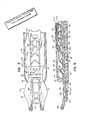
- Fig. 1 is an exploded perspective view of the present invention.
- Fig. 2 is a cross sectional view of the present invention taken along line 2-2 of Fig. 10.
- Fig. 3 is a cross sectional view of the present invention taken along line 3-3 of Fig. 6.
- Fig. 4 is a partial top cross sectional view of the present invention as depicted in Fig. 5.
- Fig. 5 is a side cross-sectional view of the present invention in an at rest position .with the jaws fully opened and a clip loaded between the jaws.
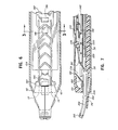
- Fig. 6 is a partial top view of the present invention as shown in Fig. 7.
- Fig. 7 is a side cross-sectional view of the present invention with the jaws in a fully closed position.
- Fig. 8 is a partial top view of the instrument shown in Fig. 9.
- Fig. 9 is a side cross-sectional view of the present invention returning to an unactuated position with the jaws slightly open and the clips being advanced.
- Fig. 10 is a partial top view of the instrument shown in Fig. 11.
- Fig. 11 is a side cross-sectional view of the present invention returning to the at rest position with the jaws fully open and the forwardmost clip on the clip load platform.
- Fig. 12A is a partial top view of the actuating mechanism of the present invention in an at rest position with the handles fully open.
- Fig. 12B is a partial top view of the present invention showing the handles partially closed with the ram and drawbar extension moving rearward.
- Fig. 12C is a partial top view of the present invention shwoing the handles fully closed.
- Fig. 13 is a side cross sectional view of the actuating or transmission mechanism of the present invention.
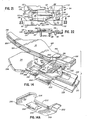
- Fig. 14 is a partial perspective view of the forward end of the instrument of the present invention showing a clip positioned on the clip load platform ready for advancement into the jaws.
- Fig. 14A is a partial bottom perspective view of the clipboard platform and tissue stop.
- Fig. 15 is a top view of the lockout mechanism of the present invention shown while the instrument is in an unactuated position.
- Fig. 16 is a top view of the lockout mechanism of the present invention shown partially actuated when the drawbar extension has just engaged the drawbar.
- Fig. 17 is a top view of the lockout mechanism of the present invention shown partially actuated when the ram has just engaged the locking tab on the gear housing.
- Fig. 18 is a top view of the lockout mechanism of the present invention shown partially actuated with the drawbar lug further retracted and the lockout mechanism about to disengage the camming member of the compound gear.
- Fig. 19 is a top view of the lockout mechanism of the present invention shown with the drawbar lug preventing the lockout mechanism from returning to its unactuated position and the - camming member completely disengaged from the lockout mechanism.
- Fig. 20 is a top view of the lockout mechanism of the present invention shown in position to prevent actuation of the instrument before a clip is properly positioned in the jaws.
- Fig. 21 is a top view of the gear housing and drawbar extension.
- Fig. 22 is a side view of the gear housing and drawbar extension taken along line 22-22 of Fig. 21.
- Fig. 24 is a partial top view of the transmission mechanism of the present invention showing the ram locked to the gear housing and the modified tooth of the compound spur gear disengaging the idler gear.
- Fig. 25 is an enlarged exploded view of the modified tooth of the compound gear reengaging the idler gear.
- Figs. 26 and 27 are elevated perspective views of the lockout member of the present invention.
- Fig. 28 is a top view of the lockout member of the present invention.
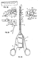
- Fig. 29 is a top view of the hemostatic clip applier of the present invention.
- The present invention relates to a multiple count clip applier for applying surgical clips to blood vessels, veins or arteries to occlude the flow of blood. The clip applier of the present invention employs a novel transmission mechanism for translating the radial or arcuate closure of the instrument handles into linear or reciprocable movement of the jaws. Indeed, by closing the instrument handles, the jaws of the present invention are retracted into a chassis or main body and cammed closed to deform a clip positioned between the jaws. Upon release of the handles the forwardmost clip in the clip housing is advanced and positioned between the jaws. Moreover, the transmission mechanism employs a unique gear arrangement for sequentially activating the instrument componentry.
- The instrument further maintains positive control of the clips as they are fed and transferred through the instrument to the jaws. Included in the positive control are a pair of springs which assist in the transfer of the clips from the clip housing to a clip load platform aligned with the jaws. Moreover, because of this positive control, the instrument can be operated at any angle or in any position and the clips will still be properly advanced to the instrument jaws. To prevent the instrument from being actuated during transfer of a clip from the clip housing to the jaws, the present invention further incorporates a novel lockout mechanism which prevents reactuation of the instrument until after the complete clip feeding process has occurred.
- The relationship and workings of the various elements of the invention will be better understood by the following detailed description. However, the embodiment of the invention described below is by way of example only and applicants do not limit themselves to the embodiment. Furthermore one should understand that the drawings are not to scale and that the embodiments are illustrated by graphic symbols and fragmentary views. In certain instances, the applicant may have omitted details which are not necessary for an understanding of the present invention such as conventional details of fabrication and assembly.
- When the clip applicator of the present invention is in an unactuated position, a clip is loaded in the jaw and the instrument is ready for use. Clip deformation occurs upon closure of the instrument handles and clip feed to the jaws occurs upon opening of the instrument handles. With the clip in place and ready for deformation, the surgeon can instantaneously place the instrument in position and deform the forwardmost clip about a blood vessel without experiencing any delay associated with having to first advance the clip to the jaws. As a result, the instrument is always ready for use.
- Turning now to the drawings, the
clip applicator 10 of the present invention, shown in Fig. 29, will be described. As can be seen, the clip applicator is provided with a forwardoperational end 12 which includes a pair ofopposed jaws 14 for deforming surgical clips and a rearward actuatingend 16 which includes a pair ofhandles 18. Operatively interconnected between the handles and the jaws is a clip housing orcartridge 20 which stores a supply of surgical clips and feeds a single clip to the jaws of the instrument for each complete actuation of the instrument. - In an unactuated state, a clip is positioned in the jaws ready for deformation about a blood vessel. In operation, the surgeon locates a blood vessel between the clip loaded in the
jaws 14 and then completely closes thehandles 18 causing thejaws 14 to deform the clip about the blood vessel. Upon opening of thehandles 18 the next clip is fed to thejaws 14, and the instrument is ready to be activated again. - As is best seen in Fig. 1, the preferred embodiment of the applicator is provided with a
chassis 22 which acts as the central supporting structure for the entire apparatus. Thechassis 22 is a single unitary structure which runs the length of the instrument and provides both structural strength to the instrument and further improves the functioning of the instrument by insuring proper alignment of all other component members. Thechassis 22 has an elongated channel shaped forward end 24 which contains and supports the clip housing orclip cartridge 20, a clipload platform member 26 for receiving the clips from the clip housing and for positioning the clips for entry into thejaws 18, a ram orclip advancer 28 for advancing the clips from theclip load platform 26 to thejaws 18 of the instrument, a pair ofjaws 18, and adrawbar 30 interconnecting thejaws 18 to the actuating ortransmission mechanism 32 of the instrument, and atissue stop 34 for preventing a blood vessel from pushing a clip back into the instrument once the clip is loaded or positioned in the jaws of the instrument. - Described in more detail, the channel shaped forward end 24 of the
chassis 22 includes abase 36 and two sidewalls with a pair ofinternal shoulders 40 formed at the junction of the base and sidewalls. The forward or distal ends of the twosidewalls 38 are turned slightly inwardly to form a pair of opposed camming surfaces 42. Additionally, thesidewalls 38 are provided with a series ofupstanding tabs 44 which engage a series of cooperatingslots 46 formed in theclip housing cover 50 to hold the forward end of the instrument together. - The
rearward portion 41 of thechassis 22 is an extension of thebase 36 of theelongated forward portion 24 and supports the transmission oractuating mechanism 32 of the present invention. The preferred embodiment of thetransmission mechanism 32 is shown in Figs. 1, 12 and 13 and comprises thehandles 18, adrawbar extension 52 reciprocably mounted in agear housing 54 and interconnected to the handles by a pair oflinks 56, a handle or triggerspring 58, anidler gear 60, acompound gear 62, adrawbar spring 64 and alockout member 66. As shown in Fig. 1, the applicator is further provided with acover plate 68 and abase plate 70 for enclosing and protecting these elements. Essentially, thetransmission mechanism 32 translates the arcuate closure of the instrument handles 18 into linear movement and sequentially activates both the closing and opening of thejaws 18 and the advancing or feeding of the clips within the instrument. - For a more complete understanding of the instrument, the preferred embodiment will now be described with respect to its functional characteristics.
- As previously stated, when the instrument is in an unactuated state a clip is loaded in the
jaws 18 and the handles are completely open (Figs. 4, 5 and 12A). As seen in Fig. 12B, upon closure of thehandles 18, thedrawbar extension 52 is caused to move rearwardly within thegear housing 54 as a result of its interconnection to thehandles 18 by a pair oflinks 56. Thehandles 18 pivot about thechassis 22 by means of a pair of pivot pins 72 extending through a pair ofapertures 74 in thechassis 22. Similarly, eachlink 56 is provided with anaperture 76 at each end to rotatable engage theupstanding pivots 78 at the rearward end of thedrawbar extension 52 and to rotatably engage alink pin 80 mounted midway in thehandle 18. - In the preferred embodiment, the links are attached to the jaw bar extension at separate, symetric locations rather than being overlapped and attached to the drawbar extension by a single pin. This latter, non-symetric method of attachment creates a torque on the instrument during closure of the handles which attempts to turn the instrument in the surgeon's hand during use. Because of this design, the force acting on the instrument from opposite directions during closure of the handles balances and the instrument is more stable in the hand of the surgeon.
- The
drawbar extension 52 is essentially rectangular in shape and is provided with anelongated slot 82 which defines theinterior sidewalls 84 and the interior endwalls 86 of the drawbar extension. As shown in Figs. 21 and 22, thedrawbar extension 52 is further provided with a pair of extensions or slide tabs to maintain the position and balance of the drawbar extension as it reciprocates within thegear housing 54. Thefirst tab 88 extends downwardly from the bottom of the drawbar extension and slidably engages onesidewall 90 of thegear housing 54. Thesecond tab 92 extends outwardly from the front end of the drawbar extension and slidably engages the upper surface of theother sidewall 94 of the gear housing (Figs. 12C, 24). A thirdlarger tab 96 or safety lug extends downwardly from the bottom of the drawbar extension near the interior rear end wall (Fig. 22). Thislug 96 cooperates with a lockout member 66 (Figs. 26-28) to provide the instrument with a safety feature for preventing actuation of the instrument while a clip is being transferred from theclip housing 20 to thejaws 18. - The
gear housing 54 is mounted to the rear portion of thechassis 22 by means well known in the art and is comprised of twosidewall portions base plate 98 and an axle plate 100 (Figs. 1, 21 and 22). Both thebase plate 98 and the rear portion of the chassis are provided with cut outportions drawbar safety lug 96. Eachsidewall portion vertical wall top surface slide tab 114. In operation, thedrawbar extension 52 reciprocates between thevertical walls gear housing 52. The first andsecond slide tabs drawbar extension 52 and theslide tab 114 andbase plate 98 of thegear housing 54 cooperate to maintain and slidably support thedrawbar extension 52 during this movement. - A
drawbar 30 is disposed in theforward end 24 of thechassis 22 and rests on top of the internal shoulders 40 (Figs. 1 and 3). During its rearward movement, the forwardinterior end wall 86F of the drawbar extension engages a pair ofupstanding fingers 116 on the rear end of the drawbar thereby causing thedrawbar 30 to move rearward in tandem with the drawbar extension 52 (Fig. 12B). In its rearward movement, the rear end of the drawbar maintains its elevated position with respect to thebase 118 of thechassis 22 by sliding on an upwardlyprotruding nipple 120 formed in the base of the chassis (Fig. 1) and also by sliding on top of the ram orclip advancer 28 disposed beneath the drawbar 30 (Fig. 12C). - The
jaws 18 of the instrument are interconnected to the forward end of thedrawbar 30 by means of a pair of resilient or flexible jaw arms 122 (Figs. 1 and 14) and upon rearward movement of thedrawbar 30 thejaws 18 are also drawn rearward and ultimately cammed closed (Figs. 4 and 6). The exterior edges of the jaws extend laterally outwardly to form a pair of camming surfaces 124. During the rearward movement of thejaws 18, these camming surfaces 124 contact a pair of inwardly directed vertical shoulders 42-formed at the distal end of theforward portion 24 of thechassis 22 which cause the jaws to be cammed closed thereby deforming the forwardmost clip positioned in the jaws about a blood vessel. At this point (Figs. 6 and 12C), thehandles 18 will be completely closed and rearward movement of the jaws will be terminated. - Upon release of the
handles 18 the instrument is caused to return to its unactuated position under the influence of thedrawbar spring 64 and the handle spring 58 (Figs. 1 and 13). Thedrawbar spring 64, disposed between theupstanding walls 126 formed in thebottom cover 70 of the instrument, is attached at its forward end to a downwardly dependingfinger 128 formed from the rear portion of thechassis 22 and at its rearward end to a downwardly dependingfinger 130 located at the rearward end of the drawbar. Both fingers are provided with notched ends to securely engage the spring. Thefinger 130 of the drawbar reciprocates in aslot 132 formed in the rearward portion of the chassis. Thehandle spring 58 extends between and interconnects the two handles 18. During closure of the instrument and deformation of a clip, thedrawbar spring 64 is subject to tensioning and thehandle spring 58 is subject to compression to thereby store energy in the springs. Upon release of the handles these two springs coact to open thehandles 18 and to return thedrawbar 30 anddrawbar extension 52 to their forwardmost positions which thereby causes thejaws 18 to move forward and open as well. As will be discussed below, the forces supplied by these springs also act to advance and feed a clip to the jaws. - The dual level clip housing or
cartridge 20 of the present invention is disposed along the forwardelongate portion 24 of thechassis 22 and above thedrawbar 30 and jaw arms 122 (Fig. 1). Theclip housing 20 is comprised of askirt 134 which rests on thedrawbar 30 and ahousing cover 50 which mounts on top of the skirt to form aclip storage cavity 135. In particular, as seen in Fig. 1, theskirt 134 is provided with multiple upward extendingtabs 136 having small apertures 138 formed therein which lockably engage multiple outwardly projectingknobs 140 formed in thereceptive slots 46 spaced along theclip housing cover 50. In addition, the clip housing further comprises aratchet advancer 142 which reciprocates within theskirt 134 and is interconnected to thedrawbar 30 at its rearward end, apawl 144 for advancing the clips within the clip housing and a pair ofsprings 146 disposed at the forward end of the housing cover 50 (Figs. 5, 7, 9 and 11) for assisting in advancement of the clips to the jaws of the instrument. Theratchet advancer 142 is further provided with a forwardly extending nose orkicker 148. - Besides assisting in closing the
jaws 18 of the instrument, the rearward movement of thedrawbar 30 also actuates the mechanism for advancing the clips within the clip housing. Thedrawbar 30 is provided with a horizontal slot or opening 150 near its rearward end which engages a downwardly dependingflange 152 affixed to the rearward end of theratchet advancer 142. Theratchet advancer 142 slides on top of theskirt 134 member and is guided in its movement by a first pair ofshoulders 154 formed in the clip housing cover (Fig. 3). The clips are abuttingly arranged in a continuous, forward facing line on top of theratchet advancer 142 with the final rearwardmost clip engaged in the front portion of pawl 144 (Fig. 9). Thehousing cover 50 is further provided with a second pair of inwardly directedshoulders 155 for aligning and guiding the clips resting on the ratchet advancer 142 (Fig. 3). Theratchet advancer 142 is provided with a series of recesses orcutout portions 156 for engaging and advancing the pawl 144 (Fig. 1). Theclip housing cover 50 is also provided with aratchet surface 158 formed along the inside upper surface having cut outportions 160 for cooperating with theratchet advancer 142 to engage and advance the pawl 144 (Figs. 3 and 9). - As can further be seen in Fig. 1, the
pawl 144 is provided with a notchedfront end 162 adapted to receptively engage the rearward end or crown of the clips. Additionally, thepawl 144 is provided with a downwardly extendingresilient flange 164 and an upwardly extendingresilient flange 166 for engaging the cut out portions or recesses of theratchet advancer 156 and theratchet surface 158 of thehousing cover 50, respectively. Each resilient flange is provided with a beveledforward surface 168 and a verticalrearward surface 170. Thepawl 144 is activated by the reciprocating movement of theratchet advancer 142. The flanges alternately engage and disengage the recesses of theratchet advancer 142 and theratchet surface 158 of thehousing cover 50 to advance the clips in conjunction with the reciprocating motion of theratchet advancer 142. - As stated previously, the clip cartridge has two levels of clips. Besides being stored on the
ratchet advancer 142, the preferred embodiment of the present invention places three or four clips on theskirt 134 in front of theratchet advancer 142. Theclip snap spring 172 is mounted on a pair ofposts 174 on the clip housing cover 50 (Fig. 9) and assists in the transfer of clips from theratchet advancer 142 to theskirt 134 or lower level. As shown in Figs. 4 and 5, theskirt 134 terminates before reaching the internalforward wall 176 of the clip cover to thereby define abreach 178. Thebreach 178 provides the passage for the clips to be transferred from the skirt orlower level 134 to thejaws 18 of the instrument. By employing this multiple level clip feed arrangement, the forward end of the instrument can be provided with a small profile allowing the instrument to be operated in small areas. - As seen in Figs. 4 and 5, the instrument is in an unactuated position with the forwardmost three clips on the
skirt 134 and the fourth clip in transition from the ratchet advancer orupper level 142 to a position on the skirt orlower level 134. - In operation, Figs. 1, 12, and 13, as the
drawbar 30 moves rearwardly the engagement of the downwardly dependingflange 152 of theratchet advancer 142 with the cut outportion 150 of thedrawbar 30 causes theratchet advancer 142 to move rearwardly. Similarly, the clips resting on theratchet advancer 142 are caused to be drawn rearwardly. However, rearward movement of the clips is prevented because thepawl 144 is prevented from moving rearwardly due to engagement of the verticalrearward edge 170 of the upwardly extendingresilient flange 166 in the applicable recess of theratchet surface 158 inhousing cover 50. At the same time, the downwardly dependingresilient flange 164 is caused to be cammed upwardly as theratchet advancer 142 travels rearwardly due to the engagement of the beveledforward surface 168 of the downwardly dependingresilient flange 164 with the forward edge of the applicable recess in theratchet advancer 142. As a result, while the clips have not physically moved relative to the instrument, the clips have all moved forward on the ratchet advancer as a result of its rearward movement. - During this same rearward travel of the
ratchet advancer 142, the forwardmost clip on the ratchet advancer is transferred from the ratchet advancer, Figs. 4 and 5, to the upper surface of theskirt 134, Figs. 6 and 7. As can be seen in Fig. 5, before theratchet advancer 142 begins its rearward movement, the forwardmost clip on the ratchet advancer is already in transition to the skirt orlower level 134. This clip is positively held in transition between therear tine 180 of theclip snap spring 172 and thekicker 148 extending from the front end of theratchet advancer 142. As theratchet advancer 142 retracts thekicker 148 ultimately is removed from beneath the clip and theclip snap spring 172 positions the clip on theskirt 134 while maintaining engagement with the crown or apex of the clip. (Fig. 7). - When the
ratchet advancer 142 completes its rearward travel, the jaws are completely clinched and thekicker 148 is positioned immediately behind the last or rearwardmost clip on the skirt 134 (Figs. 6 and 7). At this same point in the sequence of the instrument, the forwardmost clip on theskirt 134 is positively secured in position against the skirt by means of thefront tine 182 of theclip snap spring 172 and prevents the clip from falling off the skirt and into thebreach 178 of the jaws. In the preferred embodiment, four clips are position on the skirt at this point. It is certainly contemplated that fewer or more clips could be placed on this lower level, however, as the number of clips increases the effects of variations in clip length become more pronounced. The other clips are held in place by theshoulders 154 formed in the clip housing cover (Fig. 3). This allows the surgeon to maneuver and operate the instrument in various positions without risk of the clips moving or coming out of position and potentially jamming or fouling the instrument. - As the
handles 18 are released, thedrawbar extension 52 is caused to move forward under the influence of thedrawbar spring 64 which, in turn, causes theratchet advancer 142 to move forward as a result of their interconnection. Forward movement of theratchet advancer 142 also drives thepawl 144 forward as the backwall of the appropriate ratchet advancer recess engages thevertical wall 170 of the downwardly dependingflange 164 of thepawl 144. The forward movement of thepawl 144 relative to the stationaryclip housing cover 50 causes the forwardbeveled surface 168 of the upwardly extendingflange 166 of thepawl 144 to engage the applicable recess in theratchet surface 158 of theclip housing cover 50 and be cammed downwardly thereby allowing thepawl 144 to move freely forward. Thepawl 144 and recesses 156 and 160, respectively, formed in theratchet advancer 142 and ratchetsurface 158 of theclip housing cover 50 are designed in order that thepawl 144 advance one recess for each single actuation of the instrument. The resulting effect is that the clips on the ratchet advancer move forward one clip length as well. - Forward movement of the
ratchet advancer 142 also causes thekicker 148 on the forward end of theratchet advancer 142 to engage the crown or apex of the fourth clip on theskirt 134 and advance the four clips (Figs. 8 and 9). As the forwardmost clip is pushed forward, the legs of the clip extend past the end of theskirt 134 and into thebreach 178 above theclip load platform 26 and the crown or apex of the forwardmost clip causes theforward tine 180 of theclip snap spring 172 to deflect upwardly (Fig. 7). - Further forward movement causes the legs of the clip to contact the
clip load spring 186 thereby forcing the clip downwardly toward the clip load platform 26 (Fig. 8 and 9). The dip.load spring 186 in part overlies theclip snap spring 172 and is mounted to theclip cover 50 on the same pair ofposts 174 as the clip snap spring 172 (Fig. 9). As best seen in Figs. 2 and 14, thetine 188 of theclip load spring 186 is provided with a pair of stepped laterally extending members interconnected by a pair of outwardly slanted segments. The uppermost laterally extendingsurfaces 190 abut the top of thejaw 122 arms and prevent theclip load spring 186 from overpowering theclip load platform 26 and forcing the clip below the clip tracks 192 formed in the jaws channels. These uppermost outwardly extending lateral surfaces also act as safety features to prevent the clip load spring from becoming trapped between thejaw arms 122 to prevent closure of the jaws. - The intermediate laterally extending
surfaces 194 and the first pair of outwardly slanted surfaces create a first recess for engaging the legs of a clip. As seen in Figs. 2 and 14, this first recess horizontally centers the clip on theclip load platform 26. Moreover, as thejaw arms 122 close the outwardly slantedsegments 196 cause theclip load spring 182 to be cammed upwardly out of the way of the closingjaws arm 122. - More specifically, the forwardmost clip is engaged at three points, Fig. 9, and as it is advanced over the edge of the
skirt 134, the legs of the clip are first driven downwardly by theclip load spring 186 and subsequently, after the clip has been pushed off theskirt 134 and fully into thebreach 178, the crown apex of the clip is driven downwardly by thefront tine 180 of theclip snap spring 172 until the clip is positioned on the clip load platform 26 (Figs. 10 and 11). The positive coaction of theclip load spring 186 andclip snap spring 172 in driving the clip to theclip load platform 26 allows the instrument to be operated in any position without fear of the clip being misfed due to gravity or other negative factors. Moreover, the opposing actions of theclip load spring 186 and the resilientclip load platform 26 act to position or align the clip with the clip tracks 192 formed in the jaws 18 (Fig. 14) for subsequent advancement of the clip to the jaws. - As can be seen in Fig. 14, the
jaws 18 of the instrument are provided with a track orchannel 192 for guiding the clip between the jaws and for positioning and holding the clip during the deformation. In addition, thetips 198 of the jaws are crimped in order to prevent the clip from falling out of the front of the instrument and potentially being lost within the wound of a patient or simply delaying surgery by having to reactuate the instrument in order to advance another clip to the jaws. As also can be seen, the clip tracks are provided with sloped entry surfaces 200 to further facilitate reception and advancement of the clip. It is important that a clip be properly positioned or aligned prior to entry into thetracks 192 in order to avoid the clip becoming jammed or misfed as it slides to the forward part of the jaws. Consequently, theclip load platform 26 is resiliently affixed to the chassis of the instrument with an upward bias in order that it provide an upwardly directed spring action to counterbalance the downward action of theclip load spring 186 andclip snap spring 172. Both theclip load platform 26 andclip load spring 186 are designed to center the clip both vertically and horizontally for proper alignment with the clip tracks 192. - As can best be seen in Figs. 1 and 2, the
clip load platform 26 is mounted on the bottom of the forward portion of thechassis 22 between the twoshoulders 40 and is biased upwardly toward the jaw arms. Theclip load platform 26 is further provided with a pair of outwardly extending platform members orears 202 which abut and nest within a pair ofcut outs 204 in the jaw arms (Figs. 2 and 14). As a result, theupper surface 206 of theclip load platform 26 is coplanar with or slightly above the lower surface of the clip tracks and the clip is always properly positioned for advancement into the jaws. Because thejaw arms 122 retract during operation of the instrument, theclip load platform 26 must be designed to move in tandem with the jaw arms. To that end theclip load platform 26 has a rearwardly extending arm orcenter rib 210 which terminates in anupstanding guidepost 212. The guidepost extends into and engages aslot 214 formed in thedrawbar 30 which allows the clip load platform to retract as thedrawbar 30 retracts. - The clip is moved from the
clip load platform 26 to thejaws 18 of the instrument by means of a reciprocating ram orclip advancer 28. Theram 28 is an elongated member with agear rack 216 disposed at its rearward end and a pair of spacedextension arms 218 at its front end (Fig. 1). As is best shown in Fig. 1, aclip engaging member 220 is mounted on top of theextension arms 218 and extends forward therefrom and terminates in a notchedfront end 222 for engaging the apex or crown of a clip. The ram reciprocates along thebase 36 of theforward end 24 of thechassis 22 between theopposed shoulders 40 as shown in Fig. 3. Theslot 224 formed between theextension arms 218 allows the ram to reciprocate without interfering with the engagement of the clipstop platform guidepost 212 with thedrawbar 30. - As shown in Figs. 4 and 5, the instrument is in the fully open position and the
ram 28 is abutting the apex or crown of the clip. When the instrument is unactuated, theram 28 functions as the clip stop to prevent the clip from being forced back into the instrument. Such an occurrence could happen merely by gravity or when a surgeon moves the instrument forward after placing the clip about a blood vessel. This forward movement of the instrument in conjunction with the stationary position of the blood vessel causes the blood vessel to force the clip back into the instrument potentially causing a jam and certainly causing delay and frustration in the surgical procedure while the errant clip is retrieved. - However, in the present invention the
ram 28 cannot remain in its forward position during actuation of the instrument. The presence of the ram would prevent thejaws 18 from completely closing and this would prevent the clip from being completely clenched about the blood vessel. Consequently, the instrument provides for the ram to be withdrawn rearwardly into the instrument before the jaws are closed. Because removal of the ram leaves the clip without a clip stop, a tissue orvessel stop 34 is incorporated at the distal end of theclip load platform 26 to function in place of theram 28 during closure of the jaws in the absence of theram 28 to prevent a tissue or blood vessel from pushing a clip into the instrument. - As best shown in Figs. 14 and 14A, the
tissue stop 34 is positioned beneath thejaws 18 of the instrument and has twolateral extensions 226 which allow thetissue stop 34 to span theopen jaws 18 and prevent the tissue stop from being caught between the instrument jaws. - While it is intended that every clip will be properly formed about a blood vessel, it is realized that the present invention will be operated or tested prior to use in surgery or simply by potential purchasers in an environment without vessels or tissue for the clips to be clamped around. As a result, the deformed clips will be unattached to any stationary object and, therefore, free to possibly fall or slide into the instrument and cause a jam. To remove this remote possibility, the tissue or vessel stop is further provided with a
rectangular hole 228 in thebase 229 and a raised, forwardly slantingtooth 230 at the back side of this hole (Fig. 14A). Thetooth 230 is an extension of the extension arm orcenter rib 210 of theclip load platform 26. In addition, the side edges of the clip load platform are raised to create shoulders orside walls 232 on the clipload platform base 229. Consequently, if the instrument was actuated without a vessel or tissue, the deformed clip will slide down thebase 229 of theclip load platform 26 guided by theoutside shoulders 232 and would fall harmlessly through thehole 228 either before or after striking the raisedtooth 230 at the back end. of the hole. The forward slant of thetooth 230 acts to direct the clip downward. - Reciprocal movement of the
ram 28 is controlled by movement of thedrawbar extension 52 through the interconnection of theram 28 to thedrawbar extension 52 by acompound gear 62 and anidler gear 60. As shown in Figs. 1, 13 and 25, thecompound gear 62 and theidler gear 60 are mounted onseparate axles 234 formed in theaxle plate 100 of thegear housing 54 and which rest in a pair ofseats 236 formed on the inside surface of thebottom cover 70 of the instrument. A pair ofapertures 238, aligned with theaxles 234, are formed in the center of thechassis 22 to allow thecompound gear 62 andidler gear 60 to extend through thechassis 22. As thedrawbar extension 52 moves rearwardly, agear rack 240 formed on the inside surface of thedrawbar extension 52 causes theupper pinion gear 242 of thecompound gear 62 to rotate counterclockwise. As a result, thegear segment 244 of thecompound gear 62, disposed below thechassis 22, is caused to rotate counterclockwise and engage thelower pinion gear 246 of theidler gear 60. Rotation of thelower pinion gear 246 of theidler gear 60 causes simultaneous rotation of theupper pinion gear 248 of theidler gear 60 which, in turn, engages thegear rack 216 of the ram disposed at the rearward end of the ram. As a result, rearward movement of thedrawbar extension 52 causes theram 28 to withdraw into the instrument between the idler gear and left handvertical wall 108 of the gear housing 54 (Figs. 12B and 24). At a specific point, thegear segment 244 will disengage thelower portion 246 of theidler gear 60 causing theidler gear 60 to stop rotating. At this point, theram 28 has withdrawn sufficiently from between thejaws 18 to allow the jaws to be cammed closed without interference from the forward end of theram 28. - It is critical that the
idler gear 60 maintain this position in order that it be properly positioned to be reengaged by thegear segment 244 on the return stroke of the instrument. Consequently, at this same point in time, anotch 250 in the rearward end of theram 28 is caused to engage a protrudingtab 252 on thesidewall 108 of thegear housing 54 to lock theram 28 and theidler gear 60 in place during further actuation of the instrument (Fig. 24). The preferred embodiment may include -apad 253 disposed on thebase plate 98 of thegear housing 54 to help position the ram when it is locked in place (Fig. 24). As best seen in Fig. 12B, theram 28 is flexible so that it can pass over thetab 252 before locking in place. If theram 28 did not lock theidler gear 60 in place, theidler gear 60 may rotate after thegear segment 244 is disengaged. As a result, when thegear segment 244 attempts to re-engage theidler gear 60 the gear teeth will not be synchronized and a jam could occur. As an alternative embodiment it is contemplated that a separate member, other than theram 28 could be used to lock theidler gear 60 in position. - Because the
compound gear 62 rotates as a result of the linear movement of thedrawbar extension 52, the range of rotation of thecompound gear 62 is limited by the space available for linear movement of thedrawbar extension 52. With the movement of thedrawbar extension 52 andcompound gear 62 limited, it is desirable to minimize the amount of rotation of thecompound gear 62 necessary to safely withdraw theram 28 from thejaws 18 and allow closure of the jaws. In the preferred embodiment of the present invention, a step up ratio of 6:1 between the gear segment and upper pinion gear of the compound gear is sufficient to achieve the necessary rotation of the compound gear given the limited linear movement of the drawbar extension. Other ratios could be equally satisfactory upon modification of the gears. - Upon release of the
handles 18, thehandle spring 58 forces thehandles 18 to open and thedrawbar spring 64 acts to pull thedrawbar 30 forward. These two forces, in turn, cause thedrawbar extension 62 to move forward which causes the compound gear to reverse rotation and ultimate reengage theidler gear 60. The counter rotation of theidler gear 60, forces theram 28 forward, disengaging it from its locked position, wherein it engages a clip which has been disposed on theclip load platform 26 by means of theclip load spring 186. As theram 28 moves forward, it engages the clip resting on aclip load platform 28 and advances the clip through the clip tracks 192 formed on thejaws 18 to a forward position in the jaws. - Upon inspection of Figs. 24 and 25, it will be noted that the lead or
re-engaging tooth 254 of the gear segment of thecompound gear 62 has a modified profile. The modified profile serves two functions; to re-engage the idler gear without jamming and to overcome the static forces acting on the idler gear from its engagement with the locked ram. The shaved or cut back profile of the re- engaging tooth on thegear segment 244 coupled with theidler gear 60 being locked in position guarantee that there-engaging tooth 254 will misstooth 256 and engagetooth 258 on theidler gear 60. Moreover, to overcome the static forces holding the idler gear in position, there-engaging gear 244 must apply a force larger than the restraining force acting on theidler gear 60. Normally, when the lead tooth of a re-engaging gear along the interface between the two gears in contact is not modified, but has the same rounded profile as the other teeth, the force applied by the re-engaging gear is not fully directed to overcoming the static forces at work; only a component of this force is actually applied to overcome the static forces. In the preferred embodiment, as seen in Fig. 25, the result of the modification is that the total force applied by the re-engaging gear is normal or substantially normal to the plane where the teeth engage thereby applying the total force or a substantial portion of the total force applied by the gear segment to initiate movement of the idler gear. Consequently, the design is more efficient and requires less force to put the idler gear in motion. - The present invention is also provided with a safety or lock-out mechanism which prevents actuation of the instrument while a clip is being advanced from the clip housing to the jaws. The lockout member is shown in Figs. 26-28. As can be seen, the
lockout member 66 has anelongate spring arm 260, acenter lockout lug 262 and anelongate camming arm 264. Thelockout member 66 is activated by acam 268 disposed opposite thegear segment 244 on thecompound gear 62 and rotates about apivot 270 disposed on thebottom cover 70 of the instrument (Fig. 1). The entire lockout mechanism is shown in a side view in Fig. 23. - In an unactuated state, Fig. 15, the
spring arm 260 is restrained behind awall 272 formed in thebottom cover 70, thelockout lug 262 is positioned against a pair ofstops 274 also formed in the bottom cover and thevertical edge 276 of the distal end of thecam arm 264 is contacting thecam 268 of the compound gear 262 (Fig. 15). As thecompound gear 62 rotates, the engagement with thecam arm 264 causes thelockout member 66 to rotate about thepivot 270. In the meantime, therestrained spring arm 260 is applying a counterforce. As thecompound gear 62 continues to rotate, thelockout member 66 continues to rotate until thelockout lug 262, which extends upwardly through theelongate slot 104 in the chassis, has rotated into thewide portion 105 of the slot (Fig. 17). Simultaneous with the movement of thecompound gear 62, thedrawbar extension 52 is moving rearward. Fig. 16 shows the position of the lock outmember 66 at the point in time thedrawbar extension 52 is engaging thedrawbar 30. As previously described, thedrawbar extension 52 has a downwardly dependingsafety lug 96 which extends through theelongate slot 104 in thechassis 22 as well. Finally, thecam 268 on thecompound gear 62 rotates out of engagement with thecam arm 264 of the lockout member 66 (Fig. 18), and thesafety lug 96 has retreated to a point where it is now preventing thelockout member 66 from returning to its original position. Thesafety lug 96 continues to travel rearwardly and obstruct thelockout member 66 until thehandles 18 are completely closed (Fig. 19). - On the return stroke, the
cam 268 on thecompound gear 62 engages theopposite side 278 of the lockoutmember cam arm 264 which is beveled and causes thecam arm 264 to be pushed over the top of thecam 268 of the compound gear 62 (Fig. 20). At the same time, thesafety lug 96 is now moving forward. Ultimately, at the point in the actuating sequence of the instrument when the forwardmost clip on thelower level 134 of theclip housing 20 is being fed to theclip load platform 26 thelockout member 66 will swing back into its original position thereby blocking the rearward movement of thesafety lug 96. Consequently, if the instrument were prematurely actuated at this point, thelockout member 66 will prevent thetransmission mechanism 32 from clinching the jaws and potentially deforming a clip which is not properly positioned between the jaws. Moreover, thelockout lug 262 will remain in this obstructing position until the instrument handles 18 are fully released and the next forwardmost clip is properly positioned in the jaws of the instrument. Once thehandles 18 are fully opened, thecompound gear cam 268 will have rotated past thecam arm 264 allowing thecam arm 264 to drop back into position. Hence, upon actuation at this point, thecam arm 264 will move thelockout lug 262 out of the way to allow the clip properly positioned in the jaws to be deformed about a blood vessel. - Whereas a preferred embodiment and certain alternative designs have been shown and described herein, it will be apparent that other modifications, alterations and variations may be made by and will occur to those skilled in the art to which this invention pertains, particularly upon considering the foregoing teachings. For example, the forward clip engaging end of the clip load spring may be comprise a center tine having only a single pair of laterally extending members interconnected by a single pair of outwardly slanted segments. A spring of this shape would also act to align the clips upon transfer to the clip load platform. In addition, it is contemplated that a clip stop may be affixed to the forward end of the tissue stop to prevent rearward movement of the clips after retraction of the ram or clip advancer. It is, therefore, contemplated by the appended claims to cover any such modifications and other embodiments as incorporated those features which constitute the essential features of this invention within the true spirit and scope of the following claims.
Claims (26)
1. An apparatus for applying hemostatic clips to blood vessels, arteries, veins, tissue or the like to occlude the flow of blood, said apparatus comprising:
A. a single unitary chassis running the length of the apparatus for supplying the apparatus with structural strength, said chassis having an elongate front portion and a rear portion;
B. a pair of opposed jaws associated with the distal end of said elongate portion of said chassis for receiving and deforming a clip about a vessel;
C. a pair of handles associated with said rear portion of said chassis, said handles movable between a first open position and a second closed position;
D. clip housing and feed means mounted to said chassis and associated with said jaws to store a plurality of hemostatic clips and to serially advance the clips one at a time to said jaws;
E. transmission means operatively interconnecting said jaws, said handles and said clip housing and feed means such that upon closure of said handles said jaws are caused to move rearward with respect to said chassis and be cammed closed by said chassis to deform a clip positioned between said jaws, and upon release of said handles said jaws are caused to move forward with respect to said chassis and to open, and said clip housing and feed means is caused to feed a clip to said jaws.
2. The invention of claim 1 wherein said clip housing and feed means comprises a clip housing defining a clip storage cavity having an upper level and a lower level, said upper and lower levels containing a plurality of clips abuttingly arranged in a single forward facing row, said upper level communicating with said lower level to transfer a single clip to said lower level upon movement of said handles from said first open position to said second closed position.
3. The invention of claim 2 wherein said clip housing and feed means further comprises a clip load platform subtending and communicating with said lower level of said clip housing, said clip load platform adapted to receive a single clip from said clip housing lower level upon movement of said handles from said second closed position to said first open position.
4. The invention of claim 3 wherein said clip housing and feed means further comprises spring means associated with said clip housing for positively controlling the transfer of clips from said clip housing lower level to said clip load platform allowing the apparatus to be operated in any position.
5. The' invention of claim 4 wherein said spring means comprises a clip snap spring disposed in overlying relation with said lower level- of said clip housing and a clip load spring disposed in front of said clip snap spring, said clip snap spring comprising a forward tine for engaging the crown of the forwardmost clip on said lower level, said clip load spring comprising a forward tine having a pair of outwardly directed projections and intermediate means therebetween for engaging the legs of the forwardmost clip as it is transferred to said clip load platform and for centering said clips on said clip load platform.
6. The invention of claim 5 wherein said outward directly projected direction of said clip load spring are a pair of stepped laterally extending members and said intermediate means are defined by a pair of outwardly slanted members interconnecting said stepped laterally extending members.
7. The invention of claim 3 wherein said clip housing and feed means further comprised clip advance means for advancing a clip from said clip load platform to said jaws, said clip advance means having a first extended position between said jaws and a second retracted position behind said clip load platform.
8. The invention of claim 6 wherein said clip advance means is an elongate member having a front portion shaped to engage a clip and rear portion interconnected to said transmission means.
9. The invention of claim 7 wherein said transmission means comprises first and second reciprocating means slideably interconnected, said first reciprocating means operatively associated with said handles to translate the arcuate motion of said handles between said first open position and said second closed position into linear motion of said first reciprocating means between a first forward position and a second rearward position, said second reciprocating means operatively associated with said jaws for transferring the linear reciprocating motion of said first reciprocating means into linear reciprocating motion of said jaws to cause said jaws to move rearward and be cammed closed by said chassis.
10. The invention of claim 8 wherein said transmission means further comprises first and second gear means, said first gear means disposed on first reciprocating means and interconnected to said second gear means for imparting rotary motion to said second gear means, said second gear means interconnected to said clip advance means to cause said clip advance means to reciprocate between its first extended position and its second retracted position.
11. The invention of claim 9 wherein said second gear means comprises a compound gear having an upper gear and a lower gear attached together and rotatable about a common axis, and an idler gear having an upper gear and a lower gear attached together and rotatable about a common axis, said upper gear of said compound gear rotatably engaging said first gear means, said lower gear of said compound gear rotatably engaging said lower gear of said idler gear for a portion of its rotation and said upper gear of said idler gear engaging said clip advance means so that upon rearward movement of said first reciprocating means said first gear means causes said idler gear to rotate and said clip advance means to move from the first extended position to its second retracted position, and upon forward movement of said first reciprocating means said first gear means causes said compound gear to rotate in the opposite direction causing said idler gear to rotate in the opposite direction thereby moving said clip advance means from its second retracted position to its first extended position.
12. The invention of claim 1 wherein said clip housing and feed means comprises a clip housing mounted to said chassis having a distal open end for passage of clips stored therein to said jaws and a clip load platform subtending and communicating with said distal open end of said clip housing, said clip load platform adapted to receive a single clip from said clip housing upon movement of said handles from said second closed position to said first open position.
13. The invention of claim 12 wherein said clip housing and feed means further comprises spring means operatively associated with said distal open end of said clip housing and said clip load platform for positively controlling the transfer of clips from said clip housing to said clip load platform upon movement of said handles from said second closed position to said first open position.
14. The invention of claim 13 wherein said spring means comprises a first and second spring disposed adjacent said distal open end of said clip housing and overlying said clip load platform, said first spring acting to control the crown of a clip as it is transferred from said distal open end of said clip housing to said clip load platform and said second spring acting to control and align the legs of the clip as it is transferred from said distal open end of said clip housing to said clip load platform.
15. The invention of claim 14 wherein said second spring comprises a forward clip engaging end having a center portion and a pair of stepped laterally extending members interconnected to said center portion by a pair of outwardly. slanted members.
16. The invention of claim 3 wherein said clip load platform comprises a resilient member disposed at said distal end of said elongate forward portion of said chassis and interconnected to said transmission means for complementary reciprocable movement with said jaws, said clip load platform further comprising a pair of raised outwardly projecting platforms for receiving a clip from said clip housing and feed means.
17. The invention of claim 16 wherein said jaws are provided with a clip track for slidably receiving clips from said clip housing and feed means and are affixed to a pair of jaw arms interconnecting said jaws to said transmission means, said jaw arms being provided with a pair of cut out portions for nestably engaging said raised platform to thereby align said raised platform with said clip tracks.
18. The invention of claim 9 where the comprising lockout means operatively associated with said first reciprocating means, said lockout means acting to prevent rearward movement of said first reciprocating means while a clip is in transition from said clip housing to said jaws.
19. The invention of claim 11 further -comprising a camming member affixed to said compound gear and a lockout member operatively associated with said camming member to prevent rearward movement of said first reciprocating means while a clip is in transition from said clip housing to said jaws.
20. The invention of claim 19 wherein said first reciprocating means includes a safety lug having a forward and rearward position defined by said forward and rearward position of said first reciprocating means and said lockout member includes a body portion having a lockout lug extending upwardly from said body in the path of movement of said safety lug and the camming arm extending outwardly from said body and engaging said camming member of said compound gear so that upon rearward movement of said first reciprocating means said camming member engages said camming arm of said lockout member to move said upstanding lug from the path of said safety lug to allow said first reciprocating means to move to said second rearward position.
21. An apparatus for applying hemostatic clips comprising:
a one piece elongate chassis running the length of the apparatus for supplying structural strength to the apparatus, said chassis having a front portion and a rear portion;
a pair of opposed jaws associated with said front portion of said chassis for deforming a clip about a blood vessel;
clip housing and feed means overlying said front portion of said chassis and communicating with said jaws for storing said clips and for advancing said clips to said jaws, said clip housing and feed means including a channel shaped skirt having a bottom and two upstanding, opposed side walls, a ratchet advancer slidably supported within said skirt for supporting a plurality of the clips, a housing cover disposed in overlying relation to said ratchet advancer and attached to said skirt to create a clip storage cavity for enclosing said clips, said housing cover being provided with a ratchet surface disposed in spaced overlying relationship with said ratchet advancer, pawl means for advancing the clips through the housing, said pawl means having means for alternately engaging the ratchet advancer as the ratchet advancer moves forward such that the pawl means is moved forward with the ratchet advancer, and for engaging the ratchet surface as the ratchet advancer moves rearward to prevent rearward movement of the pawl means, and spring means for transferring the forwardmost clip from the clip housing and feed means to the clip positioning and deforming means;
clip positioning and deforming means for receiving said clips from said clip housing and feed means, advancing the clip to said jaws and deforming the clip about a vessel, said clip positioning and deforming means including a reciprocating drawbar disposed on said forward portion of said chassis and having a forward and a rearward end, said forward end defined by a pair of resilient jaw arms, said jaw arms coupled to said opposed jaws, a resilient clip load platform subtending said jaw arms and operatively associated with said clip housing and feed means to receive the forwardmost clip from said clip cartridge and feed means and position the clip for advancement to said jaws, a resilient tissue stop extending from said clip load platform and subtending said jaws for preventing a vessel from forcing a clip positioned between the jaws rearwardly into the apparatus during actuation, and an elongate clip advancer reciprocably diposed between said drawbar and said front portion of said chassis for advancing individual clips to said jaws from said clip load platform; and
transmission means for actuating said clip housing and feed means and said clip positioning and deforming means, said transmission means including a pair of handles pivotally connected to said rear portion of said chassis and movable between a first open position and a second closed position, a trigger spring for assisting in returning said handles to said first open position after being moved to said second closed position, a gear housing fixably mounted to said rear portion of said chassis, a reciprocating drawbar extension slideably mounted within said gear housing for engaging the rearward end of said drawbar, said drawbar extension further including an integral gear rack, a pair of links interconnecting said handles and said draw bar extension to transfer the radial movement of said handles into linear movement of said draw bar extension, a compound gear and an idler gear each having an upper and lower portion, said upper portion of said compound gear defining a pinion gear and engaging the rack gear of said draw bar extension, and said lower portion of said compound gear defining a gear segment for engaging and rotating said lower portion of said idler gear, said upper portion of said idler gear defining a pinion gear and engaging and reciprocating said rack gear of said ram, and a draw bar spring connected between said rearward end of said draw bar and said chassis to bias said draw bar in a forward position when said apparatus is in an unactuated position.
22. The invention of claim 3 further comprising a vessel stop attached to and extending forward from said clip load platform to prevent a blood vessel from forcing a clip rearward into the apparatus.
23. The invention of claim 22 wherein said vessel stop is provided with a pair of outwardly extending portions to prevent said vessel stop from becoming trapped between said jaws.
24. The invention of claim 23 wherein said vessel stop defines an aperture having side walls and end walls, said aperture formed for passage of clips not formed about a vessel away from said clip housing and feed means and said transmission means.
25. The invention of claim 23 wherein said vessel stop is further provided with an upstanding forward slanted tooth at the rear of said aperture to direct clips into said aperture
26. The invention of claim 25 wherein said vessel stop is provided with raised shoulders running parallel to the sides of said aperture.
Applications Claiming Priority (2)
| Application Number | Priority Date | Filing Date | Title |
|---|---|---|---|
| US07/035,074 US4850355A (en) | 1987-04-06 | 1987-04-06 | Hemostatic clip applicator for applying multiple hemostatic clips |
| US35074 | 1987-04-06 |
Publications (1)
| Publication Number | Publication Date |
|---|---|
| EP0286921A1 true EP0286921A1 (en) | 1988-10-19 |
Family
ID=21880474
Family Applications (1)
| Application Number | Title | Priority Date | Filing Date |
|---|---|---|---|
| EP88105284A Withdrawn EP0286921A1 (en) | 1987-04-06 | 1988-03-31 | Hemostatic clip applicator for applying multiple clips |
Country Status (2)
| Country | Link |
|---|---|
| US (1) | US4850355A (en) |
| EP (1) | EP0286921A1 (en) |
Cited By (12)
| Publication number | Priority date | Publication date | Assignee | Title |
|---|---|---|---|---|
| FR2679763A1 (en) * | 1991-07-31 | 1993-02-05 | Vitacorp | Surgical clamp for fitting suture clips (agraffes, staples) |
| US5211649A (en) * | 1987-02-10 | 1993-05-18 | Vaso Products Australia Pty. Limited | Venous cuff applicator, cartridge and cuff |
| WO1994024947A1 (en) * | 1993-04-30 | 1994-11-10 | Minnesota Mining And Manufacturing Company | Surgical instrument having an articulated jaw structure and a detachable knife |
| US6716232B1 (en) | 1993-04-30 | 2004-04-06 | United States Surgical Corporation | Surgical instrument having an articulated jaw structure and a detachable knife |
| WO2005110248A2 (en) * | 2004-04-16 | 2005-11-24 | Applied Medical Resources Corporation | Multi-fire surgical clip applier |
| WO2011044035A3 (en) * | 2009-10-09 | 2011-06-30 | Ethicon Endo-Surgery, Inc. | Improved clip advancer |
| US8496673B2 (en) | 2009-10-09 | 2013-07-30 | Ethicon Endo-Surgery, Inc. | Clip advancer with lockout mechanism |
| US8523882B2 (en) | 2005-04-14 | 2013-09-03 | Ethicon Endo-Surgery, Inc. | Clip advancer mechanism with alignment features |
| US8753356B2 (en) | 2005-04-14 | 2014-06-17 | Ethicon Endo-Surgery, Inc. | Surgical clip applier methods |
| US8821516B2 (en) | 2005-04-14 | 2014-09-02 | Ethicon Endo-Surgery, Inc. | Clip applier with migrational resistance features |
| US8915930B2 (en) | 2005-04-14 | 2014-12-23 | Ethicon Endo-Surgery, Inc. | Force limiting mechanism for medical instrument |
| US9370400B2 (en) | 2011-10-19 | 2016-06-21 | Ethicon Endo-Surgery, Inc. | Clip applier adapted for use with a surgical robot |
Families Citing this family (173)
| Publication number | Priority date | Publication date | Assignee | Title |
|---|---|---|---|---|
| US5197970A (en) * | 1988-01-15 | 1993-03-30 | United States Surgical Corporation | Surgical clip applicator |
| US5030226A (en) * | 1988-01-15 | 1991-07-09 | United States Surgical Corporation | Surgical clip applicator |
| US5100420A (en) * | 1989-07-18 | 1992-03-31 | United States Surgical Corporation | Apparatus and method for applying surgical clips in laparoscopic or endoscopic procedures |
| US5383881A (en) | 1989-07-18 | 1995-01-24 | United States Surgical Corporation | Safety device for use with endoscopic instrumentation |
| US5382254A (en) * | 1989-07-18 | 1995-01-17 | United States Surgical Corporation | Actuating handle for surgical instruments |
| US5253793A (en) * | 1990-09-17 | 1993-10-19 | United States Surgical Corporation | Apparatus for applying two-part surgical fasteners |
| US5156315A (en) * | 1990-09-17 | 1992-10-20 | United States Surgical Corporation | Arcuate apparatus for applying two-part surgical fasteners |
| US5129570A (en) * | 1990-11-30 | 1992-07-14 | Ethicon, Inc. | Surgical stapler |
| US5470009A (en) * | 1990-12-06 | 1995-11-28 | United States Surgical Corporation | Surgical fastening apparatus with locking mechanism |
| CA2055943C (en) * | 1990-12-06 | 2003-09-23 | Daniel P. Rodak | Surgical fastening apparatus with locking mechanism |
| DE69119607T2 (en) * | 1990-12-18 | 1996-11-14 | United States Surgical Corp | SAFETY DEVICE FOR SURGICAL CLAMPING DEVICES |
| CA2060040A1 (en) | 1991-02-08 | 1992-08-10 | Miguel A. Velez | Surgical staple and endoscopic stapler |
| US5413267A (en) * | 1991-05-14 | 1995-05-09 | United States Surgical Corporation | Surgical stapler with spent cartridge sensing and lockout means |
| CA2078794C (en) * | 1991-10-18 | 1998-10-06 | Frank J. Viola | Locking device for an apparatus for applying surgical fasteners |
| US5307976A (en) * | 1991-10-18 | 1994-05-03 | Ethicon, Inc. | Linear stapling mechanism with cutting means |
| US5395034A (en) * | 1991-11-07 | 1995-03-07 | American Cyanamid Co. | Linear surgical stapling instrument |
| CA2133687C (en) * | 1992-10-09 | 2007-03-27 | David T. Green | Surgical clip applier |
| US5725538A (en) * | 1992-10-09 | 1998-03-10 | United States Surgical Corporation | Surgical clip applier |
| US5300081A (en) * | 1992-10-09 | 1994-04-05 | United States Surgical Corporation | Surgical clip applier having clip advancement control |
| CA2107635C (en) * | 1992-10-09 | 1999-08-17 | David T. Green | Surgical clip applier |
| US5868761A (en) * | 1992-10-09 | 1999-02-09 | United States Surgical Corporation | Surgical clip applier |
| US5403327A (en) * | 1992-12-31 | 1995-04-04 | Pilling Weck Incorporated | Surgical clip applier |
| US5382255A (en) * | 1993-01-08 | 1995-01-17 | United States Surgical Corporation | Apparatus and method for assembly of surgical instruments |
| US5431668A (en) * | 1993-04-29 | 1995-07-11 | Ethicon, Inc. | Ligating clip applier |
| US5607436A (en) * | 1993-10-08 | 1997-03-04 | United States Surgical Corporation | Apparatus for applying surgical clips |
| US5527320A (en) * | 1994-02-10 | 1996-06-18 | Pilling Weck Inc. | Surgical clip applying instrument |
| US5637108A (en) * | 1994-06-15 | 1997-06-10 | United States Surgical Corporation | Surgical handle having a controlled leak passage |
| US5562655A (en) * | 1994-08-12 | 1996-10-08 | United States Surgical Corporation | Surgical apparatus having a universal handle for actuating various attachments |
| US5626585A (en) * | 1994-09-16 | 1997-05-06 | United States Surgical Corporation | Ligating clip advance |
| DE4434864C2 (en) * | 1994-09-29 | 1997-06-19 | United States Surgical Corp | Surgical staple applicator with interchangeable staple magazine |
| US5636779A (en) * | 1994-12-13 | 1997-06-10 | United States Surgical Corporation | Apparatus for applying surgical fasteners |
| US5988479A (en) * | 1994-12-13 | 1999-11-23 | United States Surgical Corporation | Apparatus for applying surgical fasteners |
| US5735445A (en) * | 1995-03-07 | 1998-04-07 | United States Surgical Corporation | Surgical stapler |
| US5706998A (en) * | 1995-07-17 | 1998-01-13 | United States Surgical Corporation | Surgical stapler with alignment pin locking mechanism |
| US5700271A (en) * | 1995-10-20 | 1997-12-23 | United States Surgical Corporation | Apparatus for applying surgical clips |
| US5700270A (en) * | 1995-10-20 | 1997-12-23 | United States Surgical Corporation | Surgical clip applier |
| US5772673A (en) * | 1996-03-07 | 1998-06-30 | United States Surgical Corporation | Apparatus for applying surgical clips |
| WO1998011814A2 (en) * | 1996-09-20 | 1998-03-26 | United States Surgical Corporation | Coil fastener applier and remover |
| US5833696A (en) * | 1996-10-03 | 1998-11-10 | United States Surgical Corporation | Apparatus for applying surgical clips |
| US6109500A (en) * | 1996-10-04 | 2000-08-29 | United States Surgical Corporation | Lockout mechanism for a surgical stapler |
| US5868759A (en) * | 1997-10-10 | 1999-02-09 | United States Surgical Corporation | Surgical clip applier |
| US6241740B1 (en) | 1998-04-09 | 2001-06-05 | Origin Medsystems, Inc. | System and method of use for ligating and cutting tissue |
| US6059799A (en) * | 1998-06-25 | 2000-05-09 | United States Surgical Corporation | Apparatus for applying surgical clips |
| US8529588B2 (en) * | 1999-01-25 | 2013-09-10 | Applied Medical Resources Corporation | Multiple clip applier apparatus and method |
| US6599298B1 (en) | 2000-10-23 | 2003-07-29 | Vitalitec International, S.A. | Automatic surgical clip applier |
| CN1310604C (en) * | 2001-10-24 | 2007-04-18 | 斯蒂芬·L.M.D.·蒂利姆 | Handle / grip and method for designing thereof |
| US6944914B2 (en) * | 2001-10-24 | 2005-09-20 | Tillim Stephen L | Handle and forceps/tweezers and method and apparatus for designing the like |
| US20060137144A1 (en) * | 2001-10-24 | 2006-06-29 | Tillim Stephen L | Handle/grip and method for designing the like |
| US7010835B2 (en) * | 2001-10-24 | 2006-03-14 | Tillim Stephen L | Parallel handle system and method for designing a parallel handle system |
| US6869435B2 (en) * | 2002-01-17 | 2005-03-22 | Blake, Iii John W | Repeating multi-clip applier |
| MXPA04009907A (en) * | 2002-04-10 | 2004-12-07 | Tyco Healthcare | Surgical clip applier with high torque jaws. |
| US7169157B2 (en) * | 2002-04-17 | 2007-01-30 | Tyco Healthcare Group Lp | Tacking tool and tack |
| EP1496807B1 (en) * | 2002-04-22 | 2017-01-04 | Covidien LP | Tack and tack applier |
| US7056330B2 (en) * | 2002-05-31 | 2006-06-06 | Ethicon Endo-Surgery, Inc. | Method for applying tissue fastener |
| US20040199205A1 (en) * | 2002-10-24 | 2004-10-07 | Tillim Stephen L. | Handle for forceps/tweezers and method and apparatus for designing the like |
| EP3170459A1 (en) | 2003-03-11 | 2017-05-24 | Covidien LP | Clip applying apparatus with angled jaw |
| WO2006034403A2 (en) | 2004-09-23 | 2006-03-30 | Tyco Healthcare Group, Lp | Clip applying apparatus and ligation clip |
| US9763668B2 (en) | 2004-10-08 | 2017-09-19 | Covidien Lp | Endoscopic surgical clip applier |
| JP4783372B2 (en) * | 2004-10-08 | 2011-09-28 | タイコ ヘルスケア グループ エルピー | Device for applying a surgical clip |
| US8409222B2 (en) | 2004-10-08 | 2013-04-02 | Covidien Lp | Endoscopic surgical clip applier |
| US7819886B2 (en) | 2004-10-08 | 2010-10-26 | Tyco Healthcare Group Lp | Endoscopic surgical clip applier |
| EP2641549B1 (en) | 2004-10-08 | 2015-08-12 | Covidien LP | An endoscopic surgical clip applier |
| US8038686B2 (en) * | 2005-04-14 | 2011-10-18 | Ethicon Endo-Surgery, Inc. | Clip applier configured to prevent clip fallout |
| US7686820B2 (en) | 2005-04-14 | 2010-03-30 | Ethicon Endo-Surgery, Inc. | Surgical clip applier ratchet mechanism |
| US7261724B2 (en) * | 2005-04-14 | 2007-08-28 | Ethicon Endo-Surgery, Inc. | Surgical clip advancement mechanism |
| US7731724B2 (en) | 2005-04-14 | 2010-06-08 | Ethicon Endo-Surgery, Inc. | Surgical clip advancement and alignment mechanism |
| US20090014002A1 (en) * | 2005-04-14 | 2009-01-15 | Honeywell International Inc. | Air filter assembly |
| US20070049947A1 (en) * | 2005-08-25 | 2007-03-01 | Microline Pentax Inc. | Cinch control device |
| US9326776B2 (en) * | 2005-09-29 | 2016-05-03 | Applied Medical Resources Corporation | Manually actuated surgical clip applier |
| USD629101S1 (en) | 2006-03-24 | 2010-12-14 | Tyco Healthcare Group Lp | Surgical clip applier |
| USD625009S1 (en) | 2006-03-24 | 2010-10-05 | Tyco Healthcare Group Lp | Surgical clip applier |
| EP1913881B1 (en) | 2006-10-17 | 2014-06-11 | Covidien LP | Apparatus for applying surgical clips |
| CA2679523C (en) | 2007-03-26 | 2015-06-23 | Tyco Healthcare Group Lp | Endoscopic surgical clip applier |
| CN101677813B (en) | 2007-04-11 | 2012-12-05 | Tyco医疗健康集团 | Surgical clip applier |
| US8465502B2 (en) * | 2008-08-25 | 2013-06-18 | Covidien Lp | Surgical clip applier and method of assembly |
| US8056565B2 (en) | 2008-08-25 | 2011-11-15 | Tyco Healthcare Group Lp | Surgical clip applier and method of assembly |
| US20110208212A1 (en) | 2010-02-19 | 2011-08-25 | Zergiebel Earl M | Surgical clip applier |
| US9358015B2 (en) | 2008-08-29 | 2016-06-07 | Covidien Lp | Endoscopic surgical clip applier with wedge plate |
| US8585717B2 (en) | 2008-08-29 | 2013-11-19 | Covidien Lp | Single stroke endoscopic surgical clip applier |
| US8267944B2 (en) * | 2008-08-29 | 2012-09-18 | Tyco Healthcare Group Lp | Endoscopic surgical clip applier with lock out |
| US8409223B2 (en) | 2008-08-29 | 2013-04-02 | Covidien Lp | Endoscopic surgical clip applier with clip retention |
| US9713471B2 (en) | 2009-01-26 | 2017-07-25 | Ethicon Endo-Surgery, Inc. | Surgical device with tandem fasteners |
| US9713468B2 (en) | 2009-01-26 | 2017-07-25 | Ethicon Endo-Surgery, Inc. | Surgical stapler for applying a large staple through a small delivery port and a method of using the stapler to secure a tissue fold |
| US8734469B2 (en) | 2009-10-13 | 2014-05-27 | Covidien Lp | Suture clip applier |
| US9186136B2 (en) | 2009-12-09 | 2015-11-17 | Covidien Lp | Surgical clip applier |
| US8545486B2 (en) | 2009-12-15 | 2013-10-01 | Covidien Lp | Surgical clip applier |
| US8403945B2 (en) | 2010-02-25 | 2013-03-26 | Covidien Lp | Articulating endoscopic surgical clip applier |
| US8968337B2 (en) | 2010-07-28 | 2015-03-03 | Covidien Lp | Articulating clip applier |
| US8403946B2 (en) | 2010-07-28 | 2013-03-26 | Covidien Lp | Articulating clip applier cartridge |
| US9011464B2 (en) | 2010-11-02 | 2015-04-21 | Covidien Lp | Self-centering clip and jaw |
| US9186153B2 (en) | 2011-01-31 | 2015-11-17 | Covidien Lp | Locking cam driver and jaw assembly for clip applier |
| US9775623B2 (en) | 2011-04-29 | 2017-10-03 | Covidien Lp | Surgical clip applier including clip relief feature |
| US20130131697A1 (en) | 2011-11-21 | 2013-05-23 | Covidien Lp | Surgical clip applier |
| US9364239B2 (en) | 2011-12-19 | 2016-06-14 | Covidien Lp | Jaw closure mechanism for a surgical clip applier |
| US9364216B2 (en) | 2011-12-29 | 2016-06-14 | Covidien Lp | Surgical clip applier with integrated clip counter |
| CN103181801B (en) * | 2011-12-30 | 2015-04-15 | 苏州天臣国际医疗科技有限公司 | Linear suturing and cutting instrument |
| US8992547B2 (en) | 2012-03-21 | 2015-03-31 | Ethicon Endo-Surgery, Inc. | Methods and devices for creating tissue plications |
| US9408610B2 (en) | 2012-05-04 | 2016-08-09 | Covidien Lp | Surgical clip applier with dissector |
| US9532787B2 (en) | 2012-05-31 | 2017-01-03 | Covidien Lp | Endoscopic clip applier |
| US9113892B2 (en) | 2013-01-08 | 2015-08-25 | Covidien Lp | Surgical clip applier |
| US9968362B2 (en) | 2013-01-08 | 2018-05-15 | Covidien Lp | Surgical clip applier |
| US9750500B2 (en) | 2013-01-18 | 2017-09-05 | Covidien Lp | Surgical clip applier |
| US9775624B2 (en) | 2013-08-27 | 2017-10-03 | Covidien Lp | Surgical clip applier |
| US10779838B1 (en) | 2013-11-13 | 2020-09-22 | Joseph W Blake, III | Instrument for serially applying clips to a surgical site |
| US9707005B2 (en) | 2014-02-14 | 2017-07-18 | Ethicon Llc | Lockout mechanisms for surgical devices |
| US10098641B1 (en) | 2014-08-21 | 2018-10-16 | Joseph W Blake, III | Jaws and cams for clip applying instruments |
| US9968363B2 (en) | 2014-10-20 | 2018-05-15 | Joseph W. Blake, III | Multi-clip applier |
| US10702278B2 (en) | 2014-12-02 | 2020-07-07 | Covidien Lp | Laparoscopic surgical ligation clip applier |
| US9931124B2 (en) | 2015-01-07 | 2018-04-03 | Covidien Lp | Reposable clip applier |
| US10368876B2 (en) | 2015-01-15 | 2019-08-06 | Covidien Lp | Endoscopic reposable surgical clip applier |
| US10292712B2 (en) | 2015-01-28 | 2019-05-21 | Covidien Lp | Surgical clip applier with integrated cutter |
| US10159491B2 (en) | 2015-03-10 | 2018-12-25 | Covidien Lp | Endoscopic reposable surgical clip applier |
| WO2017075752A1 (en) | 2015-11-03 | 2017-05-11 | Covidien Lp | Endoscopic surgical clip applier |
| US10390831B2 (en) | 2015-11-10 | 2019-08-27 | Covidien Lp | Endoscopic reposable surgical clip applier |
| JP6609699B2 (en) | 2015-11-10 | 2019-11-20 | コヴィディエン リミテッド パートナーシップ | Partially disposable surgical clip applier for endoscope |
| CA2999906A1 (en) | 2015-11-10 | 2017-05-18 | Covidien Lp | Endoscopic reposable surgical clip applier |
| WO2017120734A1 (en) | 2016-01-11 | 2017-07-20 | Covidien Lp | Endoscopic reposable surgical clip applier |
| CN108472027B (en) | 2016-01-18 | 2020-12-29 | 柯惠有限合伙公司 | Endoscopic surgical clip applier |
| CA2958160A1 (en) | 2016-02-24 | 2017-08-24 | Covidien Lp | Endoscopic reposable surgical clip applier |
| WO2017184964A1 (en) * | 2016-04-21 | 2017-10-26 | Applied Medical Resources Corporation | Laparoscopic clip applier |
| CN106073853B (en) * | 2016-06-20 | 2019-03-08 | 江苏海泽医疗科技发展有限公司 | Semi-automatic medical continuously-applied Clip Applier with biology folder casket |
| US10806464B2 (en) | 2016-08-11 | 2020-10-20 | Covidien Lp | Endoscopic surgical clip applier and clip applying systems |
| JP2019524326A (en) | 2016-08-25 | 2019-09-05 | コヴィディエン リミテッド パートナーシップ | Endoscopic surgical clip applier and clip application system |
| US10639044B2 (en) | 2016-10-31 | 2020-05-05 | Covidien Lp | Ligation clip module and clip applier |
| US10660651B2 (en) | 2016-10-31 | 2020-05-26 | Covidien Lp | Endoscopic reposable surgical clip applier |
| US10610236B2 (en) | 2016-11-01 | 2020-04-07 | Covidien Lp | Endoscopic reposable surgical clip applier |
| US10426489B2 (en) | 2016-11-01 | 2019-10-01 | Covidien Lp | Endoscopic reposable surgical clip applier |
| US10492795B2 (en) | 2016-11-01 | 2019-12-03 | Covidien Lp | Endoscopic surgical clip applier |
| US10709455B2 (en) | 2017-02-02 | 2020-07-14 | Covidien Lp | Endoscopic surgical clip applier |
| US10758244B2 (en) | 2017-02-06 | 2020-09-01 | Covidien Lp | Endoscopic surgical clip applier |
| CN110267606B (en) | 2017-02-06 | 2022-06-03 | 柯惠有限合伙公司 | Surgical clip applier with user feedback feature |
| US10660725B2 (en) | 2017-02-14 | 2020-05-26 | Covidien Lp | Endoscopic surgical clip applier including counter assembly |
| US10603038B2 (en) | 2017-02-22 | 2020-03-31 | Covidien Lp | Surgical clip applier including inserts for jaw assembly |
| US10548602B2 (en) | 2017-02-23 | 2020-02-04 | Covidien Lp | Endoscopic surgical clip applier |
| US11583291B2 (en) | 2017-02-23 | 2023-02-21 | Covidien Lp | Endoscopic surgical clip applier |
| US10675043B2 (en) | 2017-05-04 | 2020-06-09 | Covidien Lp | Reposable multi-fire surgical clip applier |
| US10722235B2 (en) | 2017-05-11 | 2020-07-28 | Covidien Lp | Spring-release surgical clip |
| US10660723B2 (en) | 2017-06-30 | 2020-05-26 | Covidien Lp | Endoscopic reposable surgical clip applier |
| US10639032B2 (en) | 2017-06-30 | 2020-05-05 | Covidien Lp | Endoscopic surgical clip applier including counter assembly |
| US10675112B2 (en) | 2017-08-07 | 2020-06-09 | Covidien Lp | Endoscopic surgical clip applier including counter assembly |
| US10863992B2 (en) | 2017-08-08 | 2020-12-15 | Covidien Lp | Endoscopic surgical clip applier |
| US10932790B2 (en) | 2017-08-08 | 2021-03-02 | Covidien Lp | Geared actuation mechanism and surgical clip applier including the same |
| US10786262B2 (en) | 2017-08-09 | 2020-09-29 | Covidien Lp | Endoscopic reposable surgical clip applier |
| US10786263B2 (en) | 2017-08-15 | 2020-09-29 | Covidien Lp | Endoscopic reposable surgical clip applier |
| US10835341B2 (en) | 2017-09-12 | 2020-11-17 | Covidien Lp | Endoscopic surgical clip applier and handle assemblies for use therewith |
| US10835260B2 (en) | 2017-09-13 | 2020-11-17 | Covidien Lp | Endoscopic surgical clip applier and handle assemblies for use therewith |
| US10653429B2 (en) | 2017-09-13 | 2020-05-19 | Covidien Lp | Endoscopic surgical clip applier |
| US10758245B2 (en) | 2017-09-13 | 2020-09-01 | Covidien Lp | Clip counting mechanism for surgical clip applier |
| US11376015B2 (en) | 2017-11-03 | 2022-07-05 | Covidien Lp | Endoscopic surgical clip applier and handle assemblies for use therewith |
| US11116513B2 (en) | 2017-11-03 | 2021-09-14 | Covidien Lp | Modular surgical clip cartridge |
| US10932791B2 (en) | 2017-11-03 | 2021-03-02 | Covidien Lp | Reposable multi-fire surgical clip applier |
| US10945734B2 (en) | 2017-11-03 | 2021-03-16 | Covidien Lp | Rotation knob assemblies and surgical instruments including the same |
| US10828036B2 (en) | 2017-11-03 | 2020-11-10 | Covidien Lp | Endoscopic surgical clip applier and handle assemblies for use therewith |
| US10722236B2 (en) | 2017-12-12 | 2020-07-28 | Covidien Lp | Endoscopic reposable surgical clip applier |
| US10743887B2 (en) | 2017-12-13 | 2020-08-18 | Covidien Lp | Reposable multi-fire surgical clip applier |
| US10959737B2 (en) | 2017-12-13 | 2021-03-30 | Covidien Lp | Reposable multi-fire surgical clip applier |
| US10849630B2 (en) | 2017-12-13 | 2020-12-01 | Covidien Lp | Reposable multi-fire surgical clip applier |
| US11051827B2 (en) | 2018-01-16 | 2021-07-06 | Covidien Lp | Endoscopic surgical instrument and handle assemblies for use therewith |
| US10993721B2 (en) | 2018-04-25 | 2021-05-04 | Covidien Lp | Surgical clip applier |
| US10786273B2 (en) | 2018-07-13 | 2020-09-29 | Covidien Lp | Rotation knob assemblies for handle assemblies |
| US11259887B2 (en) | 2018-08-10 | 2022-03-01 | Covidien Lp | Feedback mechanisms for handle assemblies |
| US11278267B2 (en) | 2018-08-13 | 2022-03-22 | Covidien Lp | Latch assemblies and surgical instruments including the same |
| US11219463B2 (en) | 2018-08-13 | 2022-01-11 | Covidien Lp | Bilateral spring for surgical instruments and surgical instruments including the same |
| US11253267B2 (en) | 2018-08-13 | 2022-02-22 | Covidien Lp | Friction reduction mechanisms for handle assemblies |
| US11344316B2 (en) | 2018-08-13 | 2022-05-31 | Covidien Lp | Elongated assemblies for surgical clip appliers and surgical clip appliers incorporating the same |
| US11033256B2 (en) | 2018-08-13 | 2021-06-15 | Covidien Lp | Linkage assembly for reusable surgical handle assemblies |
| US11051828B2 (en) | 2018-08-13 | 2021-07-06 | Covidien Lp | Rotation knob assemblies and surgical instruments including same |
| US11246601B2 (en) | 2018-08-13 | 2022-02-15 | Covidien Lp | Elongated assemblies for surgical clip appliers and surgical clip appliers incorporating the same |
| US11147566B2 (en) | 2018-10-01 | 2021-10-19 | Covidien Lp | Endoscopic surgical clip applier |
| US11524398B2 (en) | 2019-03-19 | 2022-12-13 | Covidien Lp | Gear drive mechanisms for surgical instruments |
| CN110432947A (en) * | 2019-08-09 | 2019-11-12 | 黄皆澔 | Running fire Clip Applier |
| US11779340B2 (en) | 2020-01-02 | 2023-10-10 | Covidien Lp | Ligation clip loading device |
| US11723669B2 (en) | 2020-01-08 | 2023-08-15 | Covidien Lp | Clip applier with clip cartridge interface |
Citations (4)
| Publication number | Priority date | Publication date | Assignee | Title |
|---|---|---|---|---|
| GB2088723A (en) * | 1980-11-19 | 1982-06-16 | Ethicon Inc | Multiple clip applier |
| WO1983002887A1 (en) * | 1982-02-17 | 1983-09-01 | United States Surgical Corp | Apparatus for applying surgical clips |
| EP0112980A2 (en) * | 1982-10-06 | 1984-07-11 | Charles H. Klieman | Improved spring activated hemostatic clip applicator |
| EP0207480A2 (en) * | 1985-07-01 | 1987-01-07 | Edward Weck Inc. | Automatic hemostatic clip applier |
Family Cites Families (24)
| Publication number | Priority date | Publication date | Assignee | Title |
|---|---|---|---|---|
| US4043504A (en) * | 1976-03-09 | 1977-08-23 | Senco Products, Inc. | Staple cartridge and feed means for use with a surgical stapling instrument |
| US4412539A (en) * | 1976-10-08 | 1983-11-01 | United States Surgical Corporation | Repeating hemostatic clip applying instruments and multi-clip cartridges therefor |
| CA1082552A (en) * | 1977-08-05 | 1980-07-29 | Charles H. Klieman | Hemostatic clip applicator |
| US4316468A (en) * | 1977-08-05 | 1982-02-23 | Charles H. Klieman | Surgical stapler |
| US4611595A (en) * | 1977-08-05 | 1986-09-16 | Charles H. Klieman | Spring activated hemostatic clip applicator |
| US4242902A (en) * | 1978-05-11 | 1981-01-06 | United States Surgical Corporation | Surgical clip applicator |
| US4152920A (en) * | 1977-10-17 | 1979-05-08 | United States Surgical Corporation | System for applying surgical clips |
| US4299224A (en) * | 1979-06-06 | 1981-11-10 | United States Surgical Corporation | Disposable clip applier |
| US4296751A (en) * | 1979-08-02 | 1981-10-27 | Blake Joseph W Iii | Surgical device |
| US4452357A (en) * | 1980-07-22 | 1984-06-05 | Charles H. Klieman | Surgical stapler |
| US4576166A (en) * | 1981-06-29 | 1986-03-18 | American Cyanamid Company | Surgical ligating instrument |
| US4410125A (en) * | 1981-10-02 | 1983-10-18 | United States Surgical Corporation | Surgical stapler apparatus with curved staple pusher |
| US4480641A (en) * | 1982-02-05 | 1984-11-06 | Ethicon, Inc. | Tip configuration for a ligating clip applier |
| US4471780A (en) * | 1982-02-05 | 1984-09-18 | Ethicon, Inc. | Multiple ligating clip applier instrument |
| US4478220A (en) * | 1982-02-05 | 1984-10-23 | Ethicon, Inc. | Ligating clip cartridge |
| US4512345A (en) * | 1982-09-30 | 1985-04-23 | United States Surgical Corporation | Surgical clip applying apparatus, and clips and clip train for use therein |
| US4674504A (en) * | 1982-10-06 | 1987-06-23 | Klieman Charles H | Spring activated hemostatic clip applicator |
| US4534351A (en) * | 1982-10-20 | 1985-08-13 | Senmed, Inc. | Ligator |
| US4549544A (en) * | 1983-10-31 | 1985-10-29 | Senmed, Inc. | Clip stop for a surgical ligating instrument |
| US4557263A (en) * | 1984-01-23 | 1985-12-10 | United States Surgical Corporation | Apparatus for applying surgical clips |
| US4616650A (en) * | 1984-07-27 | 1986-10-14 | United States Surgical Corporation | Apparatus for applying surgical clips |
| US4598711A (en) * | 1984-08-09 | 1986-07-08 | American Cyanamid Company | Surgical instrument |
| US4572183A (en) * | 1984-11-26 | 1986-02-25 | Senmed, Inc. | Positive feed system for a surgical ligating instrument |
| US4691853A (en) * | 1985-12-30 | 1987-09-08 | Technalytics, Inc. | Surgical stapler |
-
1987
- 1987-04-06 US US07/035,074 patent/US4850355A/en not_active Expired - Lifetime
-
1988
- 1988-03-31 EP EP88105284A patent/EP0286921A1/en not_active Withdrawn
Patent Citations (4)
| Publication number | Priority date | Publication date | Assignee | Title |
|---|---|---|---|---|
| GB2088723A (en) * | 1980-11-19 | 1982-06-16 | Ethicon Inc | Multiple clip applier |
| WO1983002887A1 (en) * | 1982-02-17 | 1983-09-01 | United States Surgical Corp | Apparatus for applying surgical clips |
| EP0112980A2 (en) * | 1982-10-06 | 1984-07-11 | Charles H. Klieman | Improved spring activated hemostatic clip applicator |
| EP0207480A2 (en) * | 1985-07-01 | 1987-01-07 | Edward Weck Inc. | Automatic hemostatic clip applier |
Cited By (28)
| Publication number | Priority date | Publication date | Assignee | Title |
|---|---|---|---|---|
| US5211649A (en) * | 1987-02-10 | 1993-05-18 | Vaso Products Australia Pty. Limited | Venous cuff applicator, cartridge and cuff |
| EP0612505A1 (en) * | 1991-07-31 | 1994-08-31 | Societe Vitacorp | Surgical forceps for applying suture clips |
| FR2679763A1 (en) * | 1991-07-31 | 1993-02-05 | Vitacorp | Surgical clamp for fitting suture clips (agraffes, staples) |
| US8403197B2 (en) | 1993-04-30 | 2013-03-26 | Covidien Lp | Surgical instrument having an articulated jaw structure and a detachable knife |
| WO1994024947A1 (en) * | 1993-04-30 | 1994-11-10 | Minnesota Mining And Manufacturing Company | Surgical instrument having an articulated jaw structure and a detachable knife |
| US5749893A (en) * | 1993-04-30 | 1998-05-12 | United States Surgical Corporation | Surgical instrument having an articulated jaw structure and a detachable knife |
| US6716232B1 (en) | 1993-04-30 | 2004-04-06 | United States Surgical Corporation | Surgical instrument having an articulated jaw structure and a detachable knife |
| US7658312B2 (en) | 1993-04-30 | 2010-02-09 | Vidal Claude A | Surgical instrument having an articulated jaw structure and a detachable knife |
| US8066168B2 (en) | 1993-04-30 | 2011-11-29 | Tyco Healthcare Group Lp | Surgical instrument having an articulated jaw structure and a detachable knife |
| WO2005110248A2 (en) * | 2004-04-16 | 2005-11-24 | Applied Medical Resources Corporation | Multi-fire surgical clip applier |
| WO2005110248A3 (en) * | 2004-04-16 | 2006-04-13 | Applied Med Resources | Multi-fire surgical clip applier |
| US7621926B2 (en) | 2004-04-16 | 2009-11-24 | Applied Medical Resources Corporation | Multi-fire surgical clip applier |
| US10667824B2 (en) | 2005-04-14 | 2020-06-02 | Ethicon Llc | Surgical clip applier methods |
| US10639045B2 (en) | 2005-04-14 | 2020-05-05 | Ethicon Llc | Clip applier with clip follower |
| US9717504B2 (en) | 2005-04-14 | 2017-08-01 | Ethicon Llc | Clip applier with migrational resistance features |
| US8523882B2 (en) | 2005-04-14 | 2013-09-03 | Ethicon Endo-Surgery, Inc. | Clip advancer mechanism with alignment features |
| US9782181B2 (en) | 2005-04-14 | 2017-10-10 | Ethicon Llc | Surgical clip applier methods |
| US8753356B2 (en) | 2005-04-14 | 2014-06-17 | Ethicon Endo-Surgery, Inc. | Surgical clip applier methods |
| US8821516B2 (en) | 2005-04-14 | 2014-09-02 | Ethicon Endo-Surgery, Inc. | Clip applier with migrational resistance features |
| US8915930B2 (en) | 2005-04-14 | 2014-12-23 | Ethicon Endo-Surgery, Inc. | Force limiting mechanism for medical instrument |
| US8496673B2 (en) | 2009-10-09 | 2013-07-30 | Ethicon Endo-Surgery, Inc. | Clip advancer with lockout mechanism |
| RU2597771C2 (en) * | 2009-10-09 | 2016-09-20 | Этикон Эндо-Серджери, Инк. | Improved clip advancer |
| CN102647948B (en) * | 2009-10-09 | 2015-05-20 | 伊西康内外科公司 | Improved clip advancer |
| AU2010303722B2 (en) * | 2009-10-09 | 2013-10-17 | Ethicon Endo-Surgery, Inc. | Improved clip advancer |
| CN102647948A (en) * | 2009-10-09 | 2012-08-22 | 伊西康内外科公司 | Improved clip advancer |
| WO2011044035A3 (en) * | 2009-10-09 | 2011-06-30 | Ethicon Endo-Surgery, Inc. | Improved clip advancer |
| US9370400B2 (en) | 2011-10-19 | 2016-06-21 | Ethicon Endo-Surgery, Inc. | Clip applier adapted for use with a surgical robot |
| US10039548B2 (en) | 2011-10-19 | 2018-08-07 | Ethicon Llc | Clip applier adapted for use with a surgical robot |
Also Published As
| Publication number | Publication date |
|---|---|
| JPS642640A (en) | 1989-01-06 |
| US4850355A (en) | 1989-07-25 |
Similar Documents
| Publication | Publication Date | Title |
|---|---|---|
| US4850355A (en) | Hemostatic clip applicator for applying multiple hemostatic clips | |
| US5049152A (en) | Hemostatic clip applicator | |
| US4430997A (en) | Multiple clip applier | |
| US4616650A (en) | Apparatus for applying surgical clips | |
| KR900004142B1 (en) | Ligature device | |
| US4500024A (en) | Multiple clip applier | |
| EP0112980B1 (en) | Improved spring activated hemostatic clip applicator | |
| EP2609875B1 (en) | Surgical clip applier with integrated clip counter | |
| JP3709223B2 (en) | Surgical instrument | |
| US4086926A (en) | Ligating and dividing organic structures | |
| EP0089737B1 (en) | Ligating clip cartridge | |
| US4674504A (en) | Spring activated hemostatic clip applicator | |
| EP1328198B1 (en) | Automatic surgical clip applier | |
| US4471780A (en) | Multiple ligating clip applier instrument | |
| EP0000875B1 (en) | Hemostatic clip applicator | |
| CA2467881C (en) | Surgical stapling instrument having a single lockout mechanism for prevention of firing | |
| EP0704190B1 (en) | Surgical clip applicator | |
| CA2485021C (en) | Surgical stapling instrument having a single lockout mechanism for prevention of firing | |
| EP2609877A1 (en) | Surgical clip applier | |
| EP0000756A1 (en) | Surgical stapler | |
| JPS58138449A (en) | Shape of leading end part of scissor mounting device for bonding | |
| JPH06277221A (en) | Apparatus for operation | |
| JPS6237983B2 (en) | ||
| US3777355A (en) | Surgical wound clip applier with disposable clip magazine | |
| JPH012640A (en) | Hemostatic forceps applicator for attaching multiple hemostatic forceps |
Legal Events
| Date | Code | Title | Description |
|---|---|---|---|
| PUAI | Public reference made under article 153(3) epc to a published international application that has entered the european phase |
Free format text: ORIGINAL CODE: 0009012 |
|
| AK | Designated contracting states |
Kind code of ref document: A1 Designated state(s): DE FR IT |
|
| 17P | Request for examination filed |
Effective date: 19890421 |
|
| STAA | Information on the status of an ep patent application or granted ep patent |
Free format text: STATUS: THE APPLICATION HAS BEEN WITHDRAWN |
|
| 18W | Application withdrawn |
Withdrawal date: 19900111 |