EP0285403A2 - Infusion pump - Google Patents
Infusion pump Download PDFInfo
- Publication number
- EP0285403A2 EP0285403A2 EP88302855A EP88302855A EP0285403A2 EP 0285403 A2 EP0285403 A2 EP 0285403A2 EP 88302855 A EP88302855 A EP 88302855A EP 88302855 A EP88302855 A EP 88302855A EP 0285403 A2 EP0285403 A2 EP 0285403A2
- Authority
- EP
- European Patent Office
- Prior art keywords
- motor
- period
- time
- during
- pump
- Prior art date
- Legal status (The legal status is an assumption and is not a legal conclusion. Google has not performed a legal analysis and makes no representation as to the accuracy of the status listed.)
- Ceased
Links
Images


Classifications
-
- A—HUMAN NECESSITIES
- A61—MEDICAL OR VETERINARY SCIENCE; HYGIENE
- A61M—DEVICES FOR INTRODUCING MEDIA INTO, OR ONTO, THE BODY; DEVICES FOR TRANSDUCING BODY MEDIA OR FOR TAKING MEDIA FROM THE BODY; DEVICES FOR PRODUCING OR ENDING SLEEP OR STUPOR
- A61M5/00—Devices for bringing media into the body in a subcutaneous, intra-vascular or intramuscular way; Accessories therefor, e.g. filling or cleaning devices, arm-rests
- A61M5/14—Infusion devices, e.g. infusing by gravity; Blood infusion; Accessories therefor
- A61M5/142—Pressure infusion, e.g. using pumps
- A61M5/145—Pressure infusion, e.g. using pumps using pressurised reservoirs, e.g. pressurised by means of pistons
- A61M5/1452—Pressure infusion, e.g. using pumps using pressurised reservoirs, e.g. pressurised by means of pistons pressurised by means of pistons
-
- A—HUMAN NECESSITIES
- A61—MEDICAL OR VETERINARY SCIENCE; HYGIENE
- A61M—DEVICES FOR INTRODUCING MEDIA INTO, OR ONTO, THE BODY; DEVICES FOR TRANSDUCING BODY MEDIA OR FOR TAKING MEDIA FROM THE BODY; DEVICES FOR PRODUCING OR ENDING SLEEP OR STUPOR
- A61M5/00—Devices for bringing media into the body in a subcutaneous, intra-vascular or intramuscular way; Accessories therefor, e.g. filling or cleaning devices, arm-rests
- A61M5/14—Infusion devices, e.g. infusing by gravity; Blood infusion; Accessories therefor
- A61M5/168—Means for controlling media flow to the body or for metering media to the body, e.g. drip meters, counters ; Monitoring media flow to the body
- A61M5/172—Means for controlling media flow to the body or for metering media to the body, e.g. drip meters, counters ; Monitoring media flow to the body electrical or electronic
-
- Y—GENERAL TAGGING OF NEW TECHNOLOGICAL DEVELOPMENTS; GENERAL TAGGING OF CROSS-SECTIONAL TECHNOLOGIES SPANNING OVER SEVERAL SECTIONS OF THE IPC; TECHNICAL SUBJECTS COVERED BY FORMER USPC CROSS-REFERENCE ART COLLECTIONS [XRACs] AND DIGESTS
- Y10—TECHNICAL SUBJECTS COVERED BY FORMER USPC
- Y10S—TECHNICAL SUBJECTS COVERED BY FORMER USPC CROSS-REFERENCE ART COLLECTIONS [XRACs] AND DIGESTS
- Y10S128/00—Surgery
- Y10S128/13—Infusion monitoring
Definitions
- the present invention relates to an infusion pump and, in particular, an infusion pump which utilizes a continuous drive propulsion means.
- stepper motors Prior art infusion pumps and, in particular, those used for medical purposes for infusing relatively small quantities of liquid over a predetermined period of time into a patient's body have typically used stepper motors to drive the pumping mechanism.
- a stepper motor allows regulated metering without the necessity for using feedback circuits.
- Stepper motors are, however, relatively expensive propulsion devices and can be somewhat inflexible where a wide range of accurately proportioned delivery rates is required in the one infusion device. They are also inefficient and have lower torque output.
- a method of controlling an infusion pump said pump including a DC motor connected by its output shaft to a reduction gearbox and thence to a rotary to linear motion converter, said converter imparting linear thrust to a syringe piston; said shaft of said DC motor also driving encoding means, said encoding means providing output pulses in proportion to angular displacement of said shaft; said method comprising: providing power to said DC motor only for a first period of time within a time window during which a first series of output pulses is produced from said encoding means; monitoring said output pulses (as said shaft of said DC motor returns to a stationary state) during a second period of time during said time window; comparing said pulses with a desired number of pulses corresponding to a predetermined volume feed rate and, on the basis of said comparison determining whether and for how long to energize said DC motor during subsequent window periods.
- a method of controlling an infusion pump said pump including a motor adapted to impart continuous rotary motion via an output shaft, said pump further including encoding means adapted to provide data indicative of rotational motion of said output shaft, said data being proportional to the angular displacement of said output shaft; said method comprising providing power to said motor only for a first period of time within a time window during which first data is produced from said encoding means; monitoring second data received from said encoding means during a second period of time immediately following said first period of time during said time window; comparing said first and second data with desired data corresponding to a predetermined volume feed rate of said infusion pump and, on the basis of said comparison, determining whether and for how long to energize said motor during subsequent window periods.
- said encoding means comprises a pulse encoder which produces output pulses proportional to angular displacement of said output shaft.
- said first data comprises pulses received from said encoder, the number of said pulses being proportional to the angular displacement of said output shaft during said first period of time during which and only during which power is provided to said motor.
- said second data comprises output pulses received from said encoding means during said second period of time, said second period of time being the time taken for said output shaft to come to a standstill following removal of power from said motor.
- said motor is a DC motor.
- Preferably said window period lies in the range of 1-5 seconds.
- said motor is not energized during said subsequent window period.
- an infusion pump including a motor adapted to impart continuous rotary motion via an output shaft, said pump further including encoding means adapted to provide data indicative of rotational motion of said output shaft, said data being proportional to the angular displacement of said output shaft; said pump further including means to provide power to said motor only for a first period of time within a time window during which first data is produced from said encoding means; comparison means for comparing said first data and second data received from said encoding means during a second period of time immediately following said first period of time during said time window with desired data corresponding to a predetermined volume feed rate of said infusion pump; said comparison means determining whether and for how long to energize said motor during subsequent window periods on the basis of the comparison.
- said encoding means comprises a pulse encoder which produces output pulses proportional to angular displacement of said output shaft.
- said first data comprises pulses received from said encoder, the number of said pulses being proportional to the angular displacement of said output shaft during said first period of time during which, and only during which, power is provided to said motor.
- said second data comprises output pulses received from said encoding means during said second period of time, said second period of time being the time taken for said output shaft to come to a standstill following removal of power from said motor.
- said motor is a DC motor.
- Preferably said time window lies in the range 1-5 seconds.
- an infusion pump said pump including a DC motor connected by its output shaft to a reduction gearbox and thence to a rotary to linear motion converter, said converter imparting linear thrust to a syringe piston; said shaft of said DC motor also driving encoding means, said encoding means providing output pulses in proportion to angular displacement of said shaft; said pump including control means to supply power to said DC motor only for a first period of time within a time window during which a first series of output pulses is produced from said encoding means; said control means monitoring said output pulses (as said shaft of said DC motor returns to a stationary state) during a second period of time during said time window; said control means comparing said pulses received during said first and said second periods and comparing said pulses with a desired number of pulses corresponding to a predetermined volume feed rate and, on the basis of said comparison, determining whether and for how long to energize said DC motor during subsequent window periods.
- the acceleration of said output shaft is approximately constant during said first period of time and deceleration of said output shaft is approximately constant during said second period of time.
- said first period of time and said second period of time are approximately equal.
- the total length of said first period of time and said second period of time does not exceed 1 second.
- said time window is approximately 4 seconds
- said reduction gearbox has a reduction ratio of approximately 700:1
- said syringe piston has an inside diameter of approximately 15 mm plus/minus 0.5 mm and said delivery rate does not exceed 5 ml/hr.
- said time window is set at approximately 2 seconds , causing the maximum delivery rate to be approximately 10 ml/hr.
- the circuit and rationale behind the preferred embodiments below described relates to providing an inexpensively constructed infusion pump drive mechanism utilizing a continuous drive type motor together with appropriate feedback means which will provide accurate delivery, or at least repeatable delivery, of predetermined amounts of liquid over preselected periods of time ranging from minutes to hours or, even, days.
- all preferred embodiments provide an inherent measure of pressure feedback which does not require the placement of a pressure sensing device in direct contact with the fluid being delivered to the patient.
- the pressure feedback is inherent in the control method of the preferred embodiments when used in association with a continuous drive type motor.
- an infusion pump assembly comprising a display 1 (digital readout for example), keyboard 2 and syringe 3.
- the device drives syringe piston 5 by means of an internal mechanism acting upon syringe actuator 4 so as to deliver liquid within the syringe 3 along delivery tube 6 to catheter/needle 7.
- Typical delivery rates for such devices in medical applications are of the order of microlitres per hour.
- the syringe drive mechanism comprises a continuous drive type motor, in this case, a DC motor 8 driving a gearbox 9 which rotates a screwdrive 11.
- the rotating motion of the screw operator 11 is converted to linear motion by the nut 12 which acts upon the syringe actuator 4.
- an optical shaft wheel encoder which provides an output pulse train via photo transistor 14 to processor 15.
- Light emitting diode 13 provides the light source for the photo transistor 14 in the encoder 10.
- the number of pulses delivered by photo transistor 14 to processor 15 is directly proportional to the angular displacement of the DC motor drive shaft and hence of the linear displacement of syringe piston 5.
- the processor 15 delivers power to the DC motor 8 for approximately 50 ms during a 4 second operational "window". During this initial 50 ms period the motor shaft will accelerate and a relatively rapid pulse train will be output from the encoder 10. During a subsequent approximately 200 ms period after power to the motor is cut off the motor shaft will run down to zero speed and this is reflected by a pulse train from the encoder 10 wherein the pulses become progressively more spaced out in time.
- Any pulses generated by the encoder 10 during a 4 second "window" are recorded by processor 15 as representative of the delivery volume of fluid during that window ie pulse count is proportional to total volume of fluid delivered.
- the processor 15 compares the total volume of fluid delivered (including that portion delivered during the 200 ms run on period) as represented by the cumulative pulse count over all window periods with the volume that should have been delivered up to the end of that 4 second window if the delivery rate as set by the user is to be maintained.
- the controller determines whether to deliver power to the DC motor during the next 4 second window, and, if so, for how long.
- the gearbox ratio is approximately 700/1 which, together with the 4 second window period allows accurately repeatable delivery rates up to approximately 1 ml per hour.
- the pulses generated during the run on period can also be used to determine the pressure of the liquid in the syringe 3. As the torque is increased on the motor due to pressure the number of pulses will reduce. The reduction in the number of pulses is a function of the load torque. Thus the microprocessor can assess these variations and determine the pressure. In extreme cases the behaviour of these pulses can also be used to determined whether the syringe is empty or, alternatively, has jammed.
- Figure 4 discloses a motor drive circuit suitable for implementing the control scheme of the first preferred embodiment.
- Light pulses are received on photo transistor 14 through the opto-encoder from light emitting diode 13 and delivered via a Schmidt trigger circuit to an input port of microprocessor 16.
- Output ports of the microprocessor 16 drive the DC motor on the basis of the programmed delivery rate in the software within the microprocessor.
- An enabling gate ensures that the motor drive cannot remain on beyond a predetermined period of time. This is a safety mechanism ensuring that the control system only drives the motor in a pulsed mode as generally intended. This prevents runaway situations if the microprocessor becomes faulty and attempts to leave the control line continuously at "on" level.
- the second embodiment operates in generally the same fashion as the fist embodiment.
- the mechanical layouts and drive train of Figures 1 and 2 are retained in this second embodiment.
- the behaviour of the motor drive during operation is generally as shown in Figure 5.
- the calculation period is considered to commence at the beginning of a "window" period and is approximately 50 ms in duration.
- Figure 5(a) shows the pulse output behaviour of the encoder 10 as well as a velocity/time characteristic of the drive train for a slow delivery rate under normal load conditions.
- Figure 5(b) provides similar data for a fast delivery rate under normal load conditions.
- Figure 6 shows the circuit board interconnections and components for the electronics of the second embodiment.
- Figure 6 has been divided up into Figure 6(a) comprising the microprocessor board portion of the circuit.
- Figure 6(b) comprising the power electronics control board and power electronics motor board and
- Figure (c) comprising the electronics for the display of the device of the second embodiment.
- the component types and interconnections are as shown in Figure 6.
- Figure 7 shows the software logic flow for the second embodiment as programmed into the microprocessor of Figure 6.
- the task of Figure 7 is initiated by an interrupt to the microprocessor at point A.
- the calculation period (CP) commences.
- the calculation period (CP) has essentially terminated with a decision having been made on the basis of stored information and pulse count information as to whether to start the motor or not during this "window" period.
- the "motor on” period (AA of Figure 5) and the “motor off - run down period” (BB of Figure 5) have just finished.
- point D of the flow chart of Figure 7 checks have been made to determine whether there appears to be too much pressure in the fluid delivery chamber of the syringe 3 and/or whether there has been a "delivery error" (less than expected minimum number of pulse counts received during the window period).
- the operator of the second embodiment applies a filled syringe to the drive assembly as generally showing in Figure 1.
- the assembly can be primed by placing the unit in "prime” mode by use of the mode push button 2.2 and the enter button 2.1. In this mode, by continuously holding the "enter” button 2.1 on the drive assembly will continuously operate so as to ensure that there is fluid along the complete length of the supply line and catheter 6, 7.
- "Feed rate enter” mode is then selected by use of the mode push button 2.2 and the enter push button 2.1.
- a specific feed rate is then selected by use of the increase or decrease push buttons 2.3, 2.4.
- the unit is then placed in "locked” mode whereby the first "calculation period” is initiated.
- the needle 7 is connected appropriately to the patient or other volume or body to which the fluid is to be delivered. The delivery rate is shown in the display 1 and this rate will be delivered continuously whilst the unit remains in operational mode and no error condition is detected.
- Motor operation and pulse monitoring is microprocessor controlled.
- the microprocessor 16 generates a second operating cycle upon which drug delivery calculations are based. Using data held in permanent memory and data entered via the keypad, the number of pulses to be delivered each 4 seconds, to maintain the rate set by the user, is calculated. This calculation is carried out immediately following each 4 second processor interrupt and is termed the calculation period (CP in the Figures). Experimentation has shown that for small motor operating periods and normal load conditions, motor acceleration and deceleration are approximately equivalent and constant. The processor therefore delivers power to the motor and counts the incoming pulses until half the required total for the "window" period has been received. The processor then cuts power to the motor and continues to count the incoming pulses until the time between pulses is great enough for the processor to conclude that the motor has stopped.
- the pulse count is recorded by the microprocessor as representing the volume of fluid ie pulse count is proportional to total volume of fluid delivered.
- the processor compares the total volume of fluid delivered (including the portion delivered during the motor run on period) with the volume that should have been delivered during the "window” period. The difference is recorded in memory as an error term and is added to the pulses to be delivered at the start of the next 4 second "window" period.
- a minimum number of pulses to be delivered per event is incorporated in the software.
- the processor will not activate the motor until this number is reached.
- the motor will typically only be energized once every five or six 4 second intervals. Under fast feed conditions, the motor is energized during each interval.
- a gearbox ratio of 700:1 a screw operator pitch of 0.5mm and the 4 second operating cycle will allow accurately repeatable delivery rates from approximately 5ul/hr up to approximately 5 ml/hour when used in conjunction with commercially available 10 ml syringes (of approximately 15mm diameter ).
- Delivery rates in the range of 10ul/hr up to 10ml/hr can be achieved by reducing the window period to 2 seconds (and otherwise leaving all parameters the same) Other ranges can be accommodated by suitable variation of one or more of these parameters.For very large delivery rates it can be most appropriate to use a larger diameter syringe.
- the pulses generated during the run-on period can be used to determine pressure conditions of the liquid in the syringe. Under no load and light load conditions deceleration of the motor is less than acceleration thus the number of motor run-on pulses is high. This will simply mean that the processor will not activate the motor again until enough pulses have been accumulated to compensate for the large error term as well as meet the minimum pulse number criteria.
- the microprocessor can assess these variations and determine abnormal pressure conditions. In extreme cases the behaviour of the pulses can also be used to determine whether the syringe is empty or, alternatively, has jammed.
- Tables 1, 2 and 3 provide specific examples of calculations carried out by the microprocessor over 10 window periods for the cases of "normal load”, “no load” and “heavy load” respectively and exemplify the algorithm used in the preferred embodiment flowchart of Fig 7.
- the syringe drive mechanism comprises a frame 21, support rails 22, motor assembly 23, screw operator 27, syringe plunger driver 25 and ballbearing 24.
- the motor assembly 23 is clamped to the frame by screws 29.
- the screw operator 27 is supported at one end by bearing 24 located at one end of the frame 21.
- the screw operator 27 is supported at its other end by the motor shaft 28.
- the rotary motion of the motor shaft 28 is transmitted to the screw operator 27 by means of a screw 29 which clamps a boss 30 to the motor output shaft 28.
- a pair of half nuts 31a, 31b Located within a housing in the syringe plunger driver 25 is a pair of half nuts 31a, 31b supported symmetrically on a pivot pin 32. The nuts are held together on the pin 32 by means of spring 33 and spring retainers 34.
- the half nut pair 31a, 31b close about the screwed shaft of the screw operator 27 and thereby convert the rotary motion of the screw operator 27 to a linear motion as a result of the engagement of the threaded portions 34a, 34b of the half nuts 31a, 31b.
- the syringe plunger driver can be quickly moved to a new position by disengaging the half nut pair from the screw operator by firstly urging the top portion of each member of the half nut pair inwardly towards the other so as to disengage the half nut pair from the screw operator 27 followed by a longitudinal manual shifting of the half nut pair assembly (together with the connected syringe portion 5) along the support rails 22.
- the motor assembly 23 comprises a reduction gearbox 35, a permanent magnet DC motor 36 and an optical shaft encoder assembly 37.
- the optical shaft encoder 37 delivers pulses in direct proportion to the angular displacement of the shaft 28 of the DC motor 36. The number of pulses is hence also proportional to the linear displacement of the syringe plunger driver and hence also to the syringe plunger 5 when engaged in the slot 38.
- the three items comprising the motor assembly 23 in the second preferred embodiment can be purchased from "Escap” of Switzerland as DC gearmotor part number M1616C11-205 combined with a type C optical encoder.
- This unit provides a maximum static torque of 100mNm and a maximum dynamic torque of 50 mNm for a gearbox reduction ratio of 729:1 at a terminal voltage of 6 volts.
- One of the half nut pair 31b has a leading portion 39 of its thread 34b removed in order to prevent this member of the pair from automatically disengaging due to an observed frictional coupling between it and the screw operator whilst the screw operator is rotating and driving the syringe plunger driver under load.
- FIG. 9 there is shown a form of "universal" coupling which allows latitude for misalignment between the shaft 28 and the screw assembly 27.
- This assembly of Figure 9 can be used with either the first or second embodiments and replaces the boss 30 shown in Figure 8.
- the universal coupling of Figure 9 comprises a toothed washer 39 having a "D" shaped hole in its centre adapted to engage the gearbox shaft 28 about its portion having a flat thereon.
- the teeth of the washer 40 engage with recesses 41 in boss 42 which is clamped to the screw operator 27.
- FIG. 10 there is shown an alternative way of preventing the half nut pair 31a, 31b from inadvertently, uncontrollably or accidentally being disengaged from the screw shaft 27.
- half nuts 50 and 51 are joined by means of a pivot pin 52 passing through holes in the half nuts as shown.
- the half nut pair 50, 51 is maintained in its normal engaged position by compression spring 53 acting to push the top portions of the half nut pair away from each other about the axis 52.
- a locking pin 53 is supported within the syringe plunger driver as shown such that when the end of the plunger portion of syringe 5 is engaged in the slot portion 54 the pin 53 is pushed laterally so as to have at least a portion of its length located between the opposed end portions of the half nut pair 50, 51.
- the diameter of this portion of the pin 53 is large enough to prevent the end portions of the half nut pair 50, 51 from being able to collapse inwardly far enough to cause disengagement of the threaded portions of the half nut pair from the screw operator 27.
- control philosophy can be used with any continuous drive system including AC motor drives.
- a pulse encoder is the preferred form of obtaining volume delivery information
- other systems for example analogue systems, could be used together with analogue to digital conversion means.
- the drive mechanism and philosophy of the present invention can be used wherever accurately repeatable volumes of liquid are to be delivered over nominated periods of time. Such usage might include laboratory work with animals, food processing and areas of biotechnology.
Abstract
Description
- The present invention relates to an infusion pump and, in particular, an infusion pump which utilizes a continuous drive propulsion means.
- Prior art infusion pumps and, in particular, those used for medical purposes for infusing relatively small quantities of liquid over a predetermined period of time into a patient's body have typically used stepper motors to drive the pumping mechanism. The main reason for this appears to relate to the requirement in many infusion situations that the proportion of material delivered per unit of time must be closely regulated. A stepper motor allows regulated metering without the necessity for using feedback circuits. Stepper motors are, however, relatively expensive propulsion devices and can be somewhat inflexible where a wide range of accurately proportioned delivery rates is required in the one infusion device. They are also inefficient and have lower torque output.
- Given the preferred use of disposable components in drug delivery systems it is desirable to provide an infusion system which does not contain any invasive components in direct contact with the fluid to be delivered. This might be required if pressure feedback was desired in combination with a stepper motor drive.
- It is an object of the present invention to overcome or substantially ameliorate the abovementioned disadvantages whilst utilizing a continuous drive type motive means for the infusion pump.
- According to one aspect of the present invention there is provided a method of controlling an infusion pump, said pump including a DC motor connected by its output shaft to a reduction gearbox and thence to a rotary to linear motion converter, said converter imparting linear thrust to a syringe piston; said shaft of said DC motor also driving encoding means, said encoding means providing output pulses in proportion to angular displacement of said shaft; said method comprising:
providing power to said DC motor only for a first period of time within a time window during which a first series of output pulses is produced from said encoding means;
monitoring said output pulses (as said shaft of said DC motor returns to a stationary state) during a second period of time during said time window;
comparing said pulses with a desired number of pulses corresponding to a predetermined volume feed rate and, on the basis of said comparison determining whether and for how long to energize said DC motor during subsequent window periods. - In a further broad form there is provided a method of controlling an infusion pump, said pump including a motor adapted to impart continuous rotary motion via an output shaft, said pump further including encoding means adapted to provide data indicative of rotational motion of said output shaft, said data being proportional to the angular displacement of said output shaft; said method comprising providing power to said motor only for a first period of time within a time window during which first data is produced from said encoding means; monitoring second data received from said encoding means during a second period of time immediately following said first period of time during said time window; comparing said first and second data with desired data corresponding to a predetermined volume feed rate of said infusion pump and, on the basis of said comparison, determining whether and for how long to energize said motor during subsequent window periods.
- Preferably said encoding means comprises a pulse encoder which produces output pulses proportional to angular displacement of said output shaft.
- Preferably said first data comprises pulses received from said encoder, the number of said pulses being proportional to the angular displacement of said output shaft during said first period of time during which and only during which power is provided to said motor.
- Preferably said second data comprises output pulses received from said encoding means during said second period of time, said second period of time being the time taken for said output shaft to come to a standstill following removal of power from said motor.
- Preferably said motor is a DC motor.
- Preferably said window period lies in the range of 1-5 seconds.
- Preferably if said comparison indicates that less than a predetermined minimum amount of displacement of said output shaft is required for a subsequent window period then said motor is not energized during said subsequent window period.
- In yet a further broad form there is provided an infusion pump including a motor adapted to impart continuous rotary motion via an output shaft, said pump further including encoding means adapted to provide data indicative of rotational motion of said output shaft, said data being proportional to the angular displacement of said output shaft; said pump further including means to provide power to said motor only for a first period of time within a time window during which first data is produced from said encoding means; comparison means for comparing said first data and second data received from said encoding means during a second period of time immediately following said first period of time during said time window with desired data corresponding to a predetermined volume feed rate of said infusion pump; said comparison means determining whether and for how long to energize said motor during subsequent window periods on the basis of the comparison.
- Preferably said encoding means comprises a pulse encoder which produces output pulses proportional to angular displacement of said output shaft.
- Preferably said first data comprises pulses received from said encoder, the number of said pulses being proportional to the angular displacement of said output shaft during said first period of time during which, and only during which, power is provided to said motor.
- Preferably said second data comprises output pulses received from said encoding means during said second period of time, said second period of time being the time taken for said output shaft to come to a standstill following removal of power from said motor.
- Preferably said motor is a DC motor.
- Preferably said time window lies in the range 1-5 seconds.
- In yet a further broad form there is provided an infusion pump, said pump including a DC motor connected by its output shaft to a reduction gearbox and thence to a rotary to linear motion converter, said converter imparting linear thrust to a syringe piston; said shaft of said DC motor also driving encoding means, said encoding means providing output pulses in proportion to angular displacement of said shaft; said pump including control means to supply power to said DC motor only for a first period of time within a time window during which a first series of output pulses is produced from said encoding means; said control means monitoring said output pulses (as said shaft of said DC motor returns to a stationary state) during a second period of time during said time window; said control means comparing said pulses received during said first and said second periods and comparing said pulses with a desired number of pulses corresponding to a predetermined volume feed rate and, on the basis of said comparison, determining whether and for how long to energize said DC motor during subsequent window periods.
- Preferably the acceleration of said output shaft is approximately constant during said first period of time and deceleration of said output shaft is approximately constant during said second period of time.
- Preferably said first period of time and said second period of time are approximately equal.
- In a preferred form the total length of said first period of time and said second period of time does not exceed 1 second.
- In a particular preferred form said time window is approximately 4 seconds ,said reduction gearbox has a reduction ratio of approximately 700:1, said syringe piston has an inside diameter of approximately 15 mm plus/minus 0.5 mm and said delivery rate does not exceed 5 ml/hr.Alternatively said time window is set at approximately 2 seconds , causing the maximum delivery rate to be approximately 10 ml/hr.
- The present invention will now be described with reference to preferred embodiments wherein:
- Figure 1 is an external view of an infusion pump utilizing the motive means according to both the first and second embodiments of the present invention;
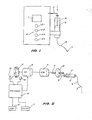
- Figure 2 is a block diagram of the components of the first and second preferred embodiments;
- Figure 3 is an indicative timing diagram of pulse trains associated with the feedback means of the first embodiment;
- Figure 4 is a schematic diagram of a circuit of the first embodiment of the present invention;
- Figure 5 is a timing and velocity/time diagram for the second embodiment;
- Figure 6 is a schematic diagram of a circuit of the second embodiment of the invention;
- Figure 7 is a flow chart for the primary control algorithm to be programmed into the microprocessor of the second embodiment;
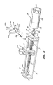
- Figure 8 is an exploded mechanical view of the drive componentry of the second embodiment;
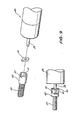
- Figure 9 is a detailed exploded view of a flexible coupling suitable for use with either the first or second embodiments; and
- Figure 10 is an exploded view of an alternative drive engagement/ disengagement mechanism suitable for use with either the first or second embodiments.
- The circuit and rationale behind the preferred embodiments below described relates to providing an inexpensively constructed infusion pump drive mechanism utilizing a continuous drive type motor together with appropriate feedback means which will provide accurate delivery, or at least repeatable delivery, of predetermined amounts of liquid over preselected periods of time ranging from minutes to hours or, even, days. Furthermore, all preferred embodiments provide an inherent measure of pressure feedback which does not require the placement of a pressure sensing device in direct contact with the fluid being delivered to the patient. In fact the pressure feedback is inherent in the control method of the preferred embodiments when used in association with a continuous drive type motor.
- Referring to Figure 1 there is shown an infusion pump assembly comprising a display 1 (digital readout for example),
keyboard 2 andsyringe 3. The device drivessyringe piston 5 by means of an internal mechanism acting uponsyringe actuator 4 so as to deliver liquid within thesyringe 3 alongdelivery tube 6 to catheter/needle 7. Typical delivery rates for such devices in medical applications are of the order of microlitres per hour. - Referring to Figure 2, some of the internal components of the infusion pump are shown. The syringe drive mechanism comprises a continuous drive type motor, in this case, a
DC motor 8 driving agearbox 9 which rotates ascrewdrive 11. The rotating motion of thescrew operator 11 is converted to linear motion by thenut 12 which acts upon thesyringe actuator 4. Also connected to the shaft of theDC motor 8 is an optical shaft wheel encoder which provides an output pulse train viaphoto transistor 14 toprocessor 15.Light emitting diode 13 provides the light source for thephoto transistor 14 in theencoder 10. The number of pulses delivered byphoto transistor 14 toprocessor 15 is directly proportional to the angular displacement of the DC motor drive shaft and hence of the linear displacement ofsyringe piston 5. - Referring to Figure 3, the behaviour of the pulse train delivered from the encoder is shown for three different delivery speed categories; namely slow, fast and very fast.
- Referring to the slow speed mode of Figure 3(a), the
processor 15 delivers power to theDC motor 8 for approximately 50 ms during a 4 second operational "window". During this initial 50 ms period the motor shaft will accelerate and a relatively rapid pulse train will be output from theencoder 10. During a subsequent approximately 200 ms period after power to the motor is cut off the motor shaft will run down to zero speed and this is reflected by a pulse train from theencoder 10 wherein the pulses become progressively more spaced out in time. - Any pulses generated by the
encoder 10 during a 4 second "window" are recorded byprocessor 15 as representative of the delivery volume of fluid during that window ie pulse count is proportional to total volume of fluid delivered. - The
processor 15 compares the total volume of fluid delivered (including that portion delivered during the 200 ms run on period) as represented by the cumulative pulse count over all window periods with the volume that should have been delivered up to the end of that 4 second window if the delivery rate as set by the user is to be maintained. - On the basis of:
total volume delivered to end of current 4 second window; and
run on characteristic
the controller determines whether to deliver power to the DC motor during the next 4 second window, and, if so, for how long. - Under slow feed conditions the processor will typically only energize the motor once every five or six window periods. Under fast feed conditions the motor is energized during each window period. (Refer faster feed characteristic in Figure 3(b).)
- Under very fast feed conditions the motor will be energized for substantially longer than 50 ms during each window and the run on period will run almost to the end of the window (Figure 3(c)). In the present embodiment a 500 ms calculation period (CP) is reserved at the end of each 4 second window during which run on pulses are not evaluated. The limit of operation for this embodiment therefore occurs when the motor power time plus the run on time equals the window period (4 seconds) less the calculation period (500 ms). If a faster delivery speed is required it will be necessary to change the gearbox ratio or alter the length of the window period.
- In the preferred embodiment of Figure 2, the gearbox ratio is approximately 700/1 which, together with the 4 second window period allows accurately repeatable delivery rates up to approximately 1 ml per hour.
- The pulses generated during the run on period can also be used to determine the pressure of the liquid in the
syringe 3. As the torque is increased on the motor due to pressure the number of pulses will reduce. The reduction in the number of pulses is a function of the load torque. Thus the microprocessor can assess these variations and determine the pressure. In extreme cases the behaviour of these pulses can also be used to determined whether the syringe is empty or, alternatively, has jammed. - Figure 4 discloses a motor drive circuit suitable for implementing the control scheme of the first preferred embodiment. Light pulses are received on
photo transistor 14 through the opto-encoder from light emittingdiode 13 and delivered via a Schmidt trigger circuit to an input port ofmicroprocessor 16. Output ports of themicroprocessor 16 drive the DC motor on the basis of the programmed delivery rate in the software within the microprocessor. - An enabling gate ensures that the motor drive cannot remain on beyond a predetermined period of time. This is a safety mechanism ensuring that the control system only drives the motor in a pulsed mode as generally intended. This prevents runaway situations if the microprocessor becomes faulty and attempts to leave the control line continuously at "on" level.
- The second embodiment operates in generally the same fashion as the fist embodiment. The mechanical layouts and drive train of Figures 1 and 2 are retained in this second embodiment.
- The behaviour of the motor drive during operation is generally as shown in Figure 5. In this embodiment the calculation period is considered to commence at the beginning of a "window" period and is approximately 50 ms in duration. Figure 5(a) shows the pulse output behaviour of the
encoder 10 as well as a velocity/time characteristic of the drive train for a slow delivery rate under normal load conditions. Figure 5(b) provides similar data for a fast delivery rate under normal load conditions. - Figure 6 shows the circuit board interconnections and components for the electronics of the second embodiment. Figure 6 has been divided up into Figure 6(a) comprising the microprocessor board portion of the circuit. Figure 6(b) comprising the power electronics control board and power electronics motor board and Figure (c) comprising the electronics for the display of the device of the second embodiment. The component types and interconnections are as shown in Figure 6.
- Figure 7 shows the software logic flow for the second embodiment as programmed into the microprocessor of Figure 6.
- The task of Figure 7 is initiated by an interrupt to the microprocessor at point A. At this point the calculation period (CP) commences. At point B on the flow chart the calculation period (CP) has essentially terminated with a decision having been made on the basis of stored information and pulse count information as to whether to start the motor or not during this "window" period. At point C the "motor on" period (AA of Figure 5) and the "motor off - run down period" (BB of Figure 5) have just finished. At point D of the flow chart of Figure 7 checks have been made to determine whether there appears to be too much pressure in the fluid delivery chamber of the
syringe 3 and/or whether there has been a "delivery error" (less than expected minimum number of pulse counts received during the window period). - In use the operator of the second embodiment (and, indeed, the first embodiment) applies a filled syringe to the drive assembly as generally showing in Figure 1. The assembly can be primed by placing the unit in "prime" mode by use of the mode push button 2.2 and the enter button 2.1. In this mode, by continuously holding the "enter" button 2.1 on the drive assembly will continuously operate so as to ensure that there is fluid along the complete length of the supply line and
catheter needle 7 is connected appropriately to the patient or other volume or body to which the fluid is to be delivered. The delivery rate is shown in thedisplay 1 and this rate will be delivered continuously whilst the unit remains in operational mode and no error condition is detected. - Referring to Figures 5, 6 and 7, detailed operation is as follows:
- Motor operation and pulse monitoring is microprocessor controlled. The
microprocessor 16 generates a second operating cycle upon which drug delivery calculations are based. Using data held in permanent memory and data entered via the keypad, the number of pulses to be delivered each 4 seconds, to maintain the rate set by the user, is calculated. This calculation is carried out immediately following each 4 second processor interrupt and is termed the calculation period (CP in the Figures). Experimentation has shown that for small motor operating periods and normal load conditions, motor acceleration and deceleration are approximately equivalent and constant. The processor therefore delivers power to the motor and counts the incoming pulses until half the required total for the "window" period has been received. The processor then cuts power to the motor and continues to count the incoming pulses until the time between pulses is great enough for the processor to conclude that the motor has stopped. - The pulse count is recorded by the microprocessor as representing the volume of fluid ie pulse count is proportional to total volume of fluid delivered.
- The processor compares the total volume of fluid delivered (including the portion delivered during the motor run on period) with the volume that should have been delivered during the "window" period. The difference is recorded in memory as an error term and is added to the pulses to be delivered at the start of the next 4 second "window" period.
- In order to maximise the efficiency of the system, a minimum number of pulses to be delivered per event is incorporated in the software. The processor will not activate the motor until this number is reached. Thus under slow feed conditions, as only a small number of pulses will be required each 4 seconds to maintain the delivery rate set by the user, the motor will typically only be energized once every five or six 4 second intervals. Under fast feed conditions, the motor is energized during each interval.
- Under very fast feed conditions, as the motor is energized for a longer period, acceleration toward the end of the motor on period is no longer constant. The limit of operation for this embodiment therefore occurs when the motor approaches a terminal velocity. If faster delivery rates are required it will be necessary to incorporate a more complex control algorithm, change the gearbox ratio, of reduce the window period to less than 4 seconds.
- In the second preferred embodiment, a gearbox ratio of 700:1 ,a screw operator pitch of 0.5mm and the 4 second operating cycle will allow accurately repeatable delivery rates from approximately 5ul/hr up to approximately 5 ml/hour when used in conjunction with commercially available 10 ml syringes (of approximately 15mm diameter ).
- Delivery rates in the range of 10ul/hr up to 10ml/hr can be achieved by reducing the window period to 2 seconds (and otherwise leaving all parameters the same) Other ranges can be accommodated by suitable variation of one or more of these parameters.For very large delivery rates it can be most appropriate to use a larger diameter syringe.
- The pulses generated during the run-on period can be used to determine pressure conditions of the liquid in the syringe. Under no load and light load conditions deceleration of the motor is less than acceleration thus the number of motor run-on pulses is high. This will simply mean that the processor will not activate the motor again until enough pulses have been accumulated to compensate for the large error term as well as meet the minimum pulse number criteria.
- Similarly, as torque is increased on the motor due to pressure, deceleration will be greater than acceleration and the number of pulses received during the motor run-on period will reduce. The reduction will be a function of the load torque. The microprocessor can assess these variations and determine abnormal pressure conditions. In extreme cases the behaviour of the pulses can also be used to determine whether the syringe is empty or, alternatively, has jammed.
- The following Tables 1, 2 and 3 provide specific examples of calculations carried out by the microprocessor over 10 window periods for the cases of "normal load", "no load" and "heavy load" respectively and exemplify the algorithm used in the preferred embodiment flowchart of Fig 7.


- Referring to Figure 8 the mechanical details of the syringe drive of the second preferred embodiment are shown. The syringe drive mechanism comprises a
frame 21, support rails 22,motor assembly 23,screw operator 27,syringe plunger driver 25 andballbearing 24. - The
motor assembly 23 is clamped to the frame by screws 29. Thescrew operator 27 is supported at one end by bearing 24 located at one end of theframe 21. Thescrew operator 27 is supported at its other end by themotor shaft 28. The rotary motion of themotor shaft 28 is transmitted to thescrew operator 27 by means of ascrew 29 which clamps aboss 30 to themotor output shaft 28. - Located within a housing in the
syringe plunger driver 25 is a pair ofhalf nuts 31a, 31b supported symmetrically on apivot pin 32. The nuts are held together on thepin 32 by means ofspring 33 andspring retainers 34. - In operational mode the
half nut pair 31a, 31b close about the screwed shaft of thescrew operator 27 and thereby convert the rotary motion of thescrew operator 27 to a linear motion as a result of the engagement of the threadedportions - The syringe plunger driver can be quickly moved to a new position by disengaging the half nut pair from the screw operator by firstly urging the top portion of each member of the half nut pair inwardly towards the other so as to disengage the half nut pair from the
screw operator 27 followed by a longitudinal manual shifting of the half nut pair assembly (together with the connected syringe portion 5) along the support rails 22. - The
motor assembly 23 comprises areduction gearbox 35, a permanentmagnet DC motor 36 and an opticalshaft encoder assembly 37. Theoptical shaft encoder 37 delivers pulses in direct proportion to the angular displacement of theshaft 28 of theDC motor 36. The number of pulses is hence also proportional to the linear displacement of the syringe plunger driver and hence also to thesyringe plunger 5 when engaged in theslot 38. - The three items comprising the
motor assembly 23 in the second preferred embodiment can be purchased from "Escap" of Switzerland as DC gearmotor part number M1616C11-205 combined with a type C optical encoder. - This unit provides a maximum static torque of 100mNm and a maximum dynamic torque of 50 mNm for a gearbox reduction ratio of 729:1 at a terminal voltage of 6 volts.
- One of the half nut pair 31b has a leading
portion 39 of itsthread 34b removed in order to prevent this member of the pair from automatically disengaging due to an observed frictional coupling between it and the screw operator whilst the screw operator is rotating and driving the syringe plunger driver under load. - Referring to Figure 9 there is shown a form of "universal" coupling which allows latitude for misalignment between the
shaft 28 and thescrew assembly 27. This assembly of Figure 9 can be used with either the first or second embodiments and replaces theboss 30 shown in Figure 8. The universal coupling of Figure 9 comprises atoothed washer 39 having a "D" shaped hole in its centre adapted to engage thegearbox shaft 28 about its portion having a flat thereon. The teeth of thewasher 40 engage withrecesses 41 inboss 42 which is clamped to thescrew operator 27. - Referring to Figure 10 there is shown an alternative way of preventing the
half nut pair 31a, 31b from inadvertently, uncontrollably or accidentally being disengaged from thescrew shaft 27. In this version (suitable for use with either the first or second embodiments of the invention)half nuts 50 and 51 (comparable to the half nuts 31b, 31a of Figure 8) are joined by means of apivot pin 52 passing through holes in the half nuts as shown. Thehalf nut pair compression spring 53 acting to push the top portions of the half nut pair away from each other about theaxis 52. A lockingpin 53 is supported within the syringe plunger driver as shown such that when the end of the plunger portion ofsyringe 5 is engaged in theslot portion 54 thepin 53 is pushed laterally so as to have at least a portion of its length located between the opposed end portions of thehalf nut pair pin 53 is large enough to prevent the end portions of thehalf nut pair screw operator 27. - When the
syringe 5 is removed thepin 53 is returned to the unlocked condition by means ofspring 54 which is retained in a compressed condition by cap 55. - The above describes only some embodiments of the present invention and modifications obvious to those skilled in the art can be made without departing from the scope and spirit of the present invention.
- For example the control philosophy can be used with any continuous drive system including AC motor drives.
- Similarly, whilst a pulse encoder is the preferred form of obtaining volume delivery information, other systems, for example analogue systems, could be used together with analogue to digital conversion means.
- In use, the drive mechanism and philosophy of the present invention can be used wherever accurately repeatable volumes of liquid are to be delivered over nominated periods of time. Such usage might include laboratory work with animals, food processing and areas of biotechnology.
- Whilst the schematic diagrams of Figure 4 and Figure 6 shows a microprocessor embodiment the algorithm of the present invention could be implemented in pure hardward fashion.
Claims (22)
Applications Claiming Priority (2)
| Application Number | Priority Date | Filing Date | Title |
|---|---|---|---|
| AUPI114087 | 1987-03-30 | ||
| AU1140/87 | 1987-03-30 |
Publications (2)
| Publication Number | Publication Date |
|---|---|
| EP0285403A2 true EP0285403A2 (en) | 1988-10-05 |
| EP0285403A3 EP0285403A3 (en) | 1989-08-16 |
Family
ID=3772088
Family Applications (1)
| Application Number | Title | Priority Date | Filing Date |
|---|---|---|---|
| EP88302855A Ceased EP0285403A3 (en) | 1987-03-30 | 1988-03-30 | Infusion pump |
Country Status (2)
| Country | Link |
|---|---|
| US (1) | US4919650A (en) |
| EP (1) | EP0285403A3 (en) |
Cited By (12)
| Publication number | Priority date | Publication date | Assignee | Title |
|---|---|---|---|---|
| EP0228786A3 (en) * | 1985-12-23 | 1988-09-21 | Nippon Telegraph And Telephone Corporation | Radio signal interference cancellation system |
| FR2647350A1 (en) * | 1989-05-25 | 1990-11-30 | Chenon Dominique | Apparatus for administering insulin to diabetics |
| FR2714293A1 (en) * | 1993-12-29 | 1995-06-30 | Zambon Spa | Process for the controlled injection of liquid into a tube and application to infusion pumps. |
| WO1996014893A1 (en) * | 1994-11-14 | 1996-05-23 | Cma/Microdialysis Ab | An infusion and microdialysis pump |
| EP0959920A1 (en) * | 1995-05-05 | 1999-12-01 | Zevex, Inc. | Pressure monitoring enteral feeding system and method |
| EP1092440A1 (en) * | 1998-07-02 | 2001-04-18 | JMS Co., Ltd. | Liquid pump |
| EP1409063A1 (en) * | 2001-07-03 | 2004-04-21 | Syntheon, LLC. | Methods and apparatus for sclerosing the wall of a varicose vein |
| WO2006020756A2 (en) * | 2004-08-10 | 2006-02-23 | Allergan, Inc. | Step by step botox injector |
| DE102004063650A1 (en) * | 2004-12-31 | 2006-07-20 | Tecpharma Licensing Ag | Injection unit comprises a sensor, an electronic circuit connected to the sensor, and an electronic, optical and/or acoustic output unit |
| DE102004063664A1 (en) * | 2004-12-31 | 2006-07-20 | Tecpharma Licensing Ag | Real-time display of a device for metered administration of a product |
| FR2883188A1 (en) * | 2005-03-18 | 2006-09-22 | Raymond Denance | Injection device for intradermal, subcutaneous/intramuscular injections, comprises a syringe fixed in a support part, moving part to push the syringe on the piston, threaded rod rotated by a control unit and hub |
| WO2015074944A1 (en) * | 2013-11-20 | 2015-05-28 | Novo Nordisk A/S | Drive mechanism for an injection device |
Families Citing this family (95)
| Publication number | Priority date | Publication date | Assignee | Title |
|---|---|---|---|---|
| US5935099A (en) | 1992-09-09 | 1999-08-10 | Sims Deltec, Inc. | Drug pump systems and methods |
| US6241704B1 (en) | 1901-11-22 | 2001-06-05 | Sims Deltec, Inc. | Drug pump systems and methods |
| US5059171A (en) * | 1990-06-21 | 1991-10-22 | Boc Health Care, Inc. | Bubble detection system |
| DE69212069T2 (en) * | 1991-05-23 | 1997-02-20 | Ivac Corp | Drive system for the piston rod of a syringe |
| US5236416A (en) * | 1991-05-23 | 1993-08-17 | Ivac Corporation | Syringe plunger position detection and alarm generation |
| US5106375A (en) * | 1991-05-23 | 1992-04-21 | Ivac Corporation | Dynamic lead screw engagement and indicator |
| JP3138065B2 (en) * | 1991-09-04 | 2001-02-26 | シャープ株式会社 | Sampling method of bubble detector in infusion device |
| JP3236057B2 (en) * | 1992-04-03 | 2001-12-04 | シャープ株式会社 | Infusion device |
| CA2137772A1 (en) * | 1992-06-09 | 1993-12-23 | Shan Padda | Programmable infusion pump with interchangeable tubing |
| US5232439A (en) * | 1992-11-02 | 1993-08-03 | Infusion Technologies Corporation | Method for pumping fluid from a flexible, variable geometry reservoir |
| US5342313A (en) * | 1992-11-02 | 1994-08-30 | Infusion Technologies Corporation | Fluid pump for a flexible, variable geometry reservoir |
| US5609575A (en) * | 1994-04-11 | 1997-03-11 | Graseby Medical Limited | Infusion pump and method with dose-rate calculation |
| US5620312A (en) * | 1995-03-06 | 1997-04-15 | Sabratek Corporation | Infusion pump with dual-latching mechanism |
| US5628619A (en) * | 1995-03-06 | 1997-05-13 | Sabratek Corporation | Infusion pump having power-saving modes |
| US5637093A (en) * | 1995-03-06 | 1997-06-10 | Sabratek Corporation | Infusion pump with selective backlight |
| US5904668A (en) * | 1995-03-06 | 1999-05-18 | Sabratek Corporation | Cassette for an infusion pump |
| US5795327A (en) * | 1995-03-06 | 1998-08-18 | Sabratek Corporation | Infusion pump with historical data recording |
| US5531680A (en) * | 1995-05-05 | 1996-07-02 | Zevex, Inc. | Enteral feeding pump motor unit and method of use |
| US5914945A (en) * | 1996-12-31 | 1999-06-22 | Northern Telecom Limited | Method and system for bandwidth allocation for multimedia services under aggregate traffic conditions |
| US6468242B1 (en) | 1998-03-06 | 2002-10-22 | Baxter International Inc. | Medical apparatus with patient data recording |
| US6423035B1 (en) | 1999-06-18 | 2002-07-23 | Animas Corporation | Infusion pump with a sealed drive mechanism and improved method of occlusion detection |
| US6428509B1 (en) | 1999-07-29 | 2002-08-06 | Alaris Medical Systems, Inc. | Syringe plunger driver system and method |
| JP2003510135A (en) | 1999-09-29 | 2003-03-18 | スターリング メディヴェイションズ インコーポレイテッド | Reusable pharmaceutical injection device |
| MXPA02011395A (en) * | 2000-05-18 | 2003-04-25 | Dentsply Int Inc | Fluid material dispensing syringe. |
| US6652493B1 (en) | 2000-07-05 | 2003-11-25 | Animas Corporation | Infusion pump syringe |
| DE60119354T2 (en) * | 2000-10-10 | 2007-04-19 | Dentsply International Inc. | Syringe for dental anesthesia |
| US6699232B2 (en) * | 2001-03-01 | 2004-03-02 | Scimed Life Systems, Inc. | Fluid injection apparatus with improved contrast visualization |
| US7044933B2 (en) * | 2001-03-01 | 2006-05-16 | Scimed Life Systems, Inc. | Fluid injection system for coronary intervention |
| DE20122407U1 (en) * | 2001-04-26 | 2005-09-15 | Groening Ruediger | Pump for administering medicaments to a human or an animal at a rate variable with time is controlled entirely or partially by means of at least one profile located on various elements |
| US8034026B2 (en) * | 2001-05-18 | 2011-10-11 | Deka Products Limited Partnership | Infusion pump assembly |
| EP1815879A3 (en) | 2001-05-18 | 2007-11-14 | Deka Products Limited Partnership | Infusion set for a fluid pump |
| US8250483B2 (en) | 2002-02-28 | 2012-08-21 | Smiths Medical Asd, Inc. | Programmable medical infusion pump displaying a banner |
| US8504179B2 (en) | 2002-02-28 | 2013-08-06 | Smiths Medical Asd, Inc. | Programmable medical infusion pump |
| US9956377B2 (en) | 2002-09-20 | 2018-05-01 | Angiodynamics, Inc. | Method and apparatus for intra-aortic substance delivery to a branch vessel |
| DE10330985A1 (en) * | 2003-07-09 | 2005-02-17 | Tecpharma Licensing Ag | Device for administering a fluid product with optical scanning |
| US8422413B2 (en) * | 2003-09-18 | 2013-04-16 | Dentsply International Inc. | Process and device for the wireless transmission of dental process data |
| US8954336B2 (en) | 2004-02-23 | 2015-02-10 | Smiths Medical Asd, Inc. | Server for medical device |
| US7608059B2 (en) * | 2004-05-25 | 2009-10-27 | Covidien Ag | Flow control apparatus |
| US20060173439A1 (en) * | 2005-01-18 | 2006-08-03 | Thorne Gale H Jr | Syringe drive system |
| US8113244B2 (en) | 2006-02-09 | 2012-02-14 | Deka Products Limited Partnership | Adhesive and peripheral systems and methods for medical devices |
| US8852164B2 (en) | 2006-02-09 | 2014-10-07 | Deka Products Limited Partnership | Method and system for shape-memory alloy wire control |
| US8141844B2 (en) * | 2005-10-26 | 2012-03-27 | Codman NeuroSciences Sàrl | Flow rate accuracy of a fluidic delivery system |
| US7798954B2 (en) | 2006-01-04 | 2010-09-21 | Allergan, Inc. | Hydraulic gastric band with collapsible reservoir |
| US8043206B2 (en) | 2006-01-04 | 2011-10-25 | Allergan, Inc. | Self-regulating gastric band with pressure data processing |
| US9492606B2 (en) | 2006-02-09 | 2016-11-15 | Deka Products Limited Partnership | Apparatus, system and methods for an infusion pump assembly |
| US11497846B2 (en) | 2006-02-09 | 2022-11-15 | Deka Products Limited Partnership | Patch-sized fluid delivery systems and methods |
| US11364335B2 (en) | 2006-02-09 | 2022-06-21 | Deka Products Limited Partnership | Apparatus, system and method for fluid delivery |
| US11478623B2 (en) | 2006-02-09 | 2022-10-25 | Deka Products Limited Partnership | Infusion pump assembly |
| US8435206B2 (en) | 2006-08-03 | 2013-05-07 | Smiths Medical Asd, Inc. | Interface for medical infusion pump |
| US8858526B2 (en) | 2006-08-03 | 2014-10-14 | Smiths Medical Asd, Inc. | Interface for medical infusion pump |
| US8149131B2 (en) | 2006-08-03 | 2012-04-03 | Smiths Medical Asd, Inc. | Interface for medical infusion pump |
| US8965707B2 (en) | 2006-08-03 | 2015-02-24 | Smiths Medical Asd, Inc. | Interface for medical infusion pump |
| US8287514B2 (en) * | 2007-09-07 | 2012-10-16 | Asante Solutions, Inc. | Power management techniques for an infusion pump system |
| US10080704B2 (en) | 2007-12-31 | 2018-09-25 | Deka Products Limited Partnership | Apparatus, system and method for fluid delivery |
| WO2009088956A2 (en) | 2007-12-31 | 2009-07-16 | Deka Products Limited Partnership | Infusion pump assembly |
| US10188787B2 (en) | 2007-12-31 | 2019-01-29 | Deka Products Limited Partnership | Apparatus, system and method for fluid delivery |
| BR122019016154B8 (en) * | 2007-12-31 | 2021-06-22 | Deka Products Lp | infusion pump set |
| US8881774B2 (en) | 2007-12-31 | 2014-11-11 | Deka Research & Development Corp. | Apparatus, system and method for fluid delivery |
| US8900188B2 (en) | 2007-12-31 | 2014-12-02 | Deka Products Limited Partnership | Split ring resonator antenna adapted for use in wirelessly controlled medical device |
| US9456955B2 (en) | 2007-12-31 | 2016-10-04 | Deka Products Limited Partnership | Apparatus, system and method for fluid delivery |
| US20090204078A1 (en) * | 2008-02-13 | 2009-08-13 | Boston Scientific Scimed, Inc. | Manifold and Valve Seal for Use with a Medical Device |
| US8133197B2 (en) | 2008-05-02 | 2012-03-13 | Smiths Medical Asd, Inc. | Display for pump |
| CA2954728C (en) | 2008-09-15 | 2019-03-26 | Deka Products Limited Partnership | Systems and methods for fluid delivery |
| US9180245B2 (en) | 2008-10-10 | 2015-11-10 | Deka Products Limited Partnership | System and method for administering an infusible fluid |
| US8016789B2 (en) | 2008-10-10 | 2011-09-13 | Deka Products Limited Partnership | Pump assembly with a removable cover assembly |
| US8262616B2 (en) | 2008-10-10 | 2012-09-11 | Deka Products Limited Partnership | Infusion pump assembly |
| US8708376B2 (en) | 2008-10-10 | 2014-04-29 | Deka Products Limited Partnership | Medium connector |
| US8066672B2 (en) | 2008-10-10 | 2011-11-29 | Deka Products Limited Partnership | Infusion pump assembly with a backup power supply |
| US8267892B2 (en) | 2008-10-10 | 2012-09-18 | Deka Products Limited Partnership | Multi-language / multi-processor infusion pump assembly |
| US8223028B2 (en) | 2008-10-10 | 2012-07-17 | Deka Products Limited Partnership | Occlusion detection system and method |
| US20100185049A1 (en) | 2008-10-22 | 2010-07-22 | Allergan, Inc. | Dome and screw valves for remotely adjustable gastric banding systems |
| US8105269B2 (en) | 2008-10-24 | 2012-01-31 | Baxter International Inc. | In situ tubing measurements for infusion pumps |
| US8137083B2 (en) | 2009-03-11 | 2012-03-20 | Baxter International Inc. | Infusion pump actuators, system and method for controlling medical fluid flowrate |
| US8382447B2 (en) | 2009-12-31 | 2013-02-26 | Baxter International, Inc. | Shuttle pump with controlled geometry |
| US8840541B2 (en) | 2010-02-25 | 2014-09-23 | Apollo Endosurgery, Inc. | Pressure sensing gastric banding system |
| US9604236B2 (en) | 2010-04-05 | 2017-03-28 | Jeffrey E. Sandahl | Fluid intake assembly for a fluid sprayer |
| US9038923B2 (en) * | 2010-04-05 | 2015-05-26 | Wagner Spray Tech Corporation | Fluid level indicator in an airless fluid sprayer |
| US8919669B2 (en) | 2010-04-05 | 2014-12-30 | Wagner Spray Tech Corporation | Fluid intake assembly for remote fluid source |
| US8939888B2 (en) | 2010-04-28 | 2015-01-27 | Apollo Endosurgery, Inc. | Method and system for determining the pressure of a fluid in a syringe, an access port, a catheter, and a gastric band |
| US20110270025A1 (en) | 2010-04-30 | 2011-11-03 | Allergan, Inc. | Remotely powered remotely adjustable gastric band system |
| US8567235B2 (en) | 2010-06-29 | 2013-10-29 | Baxter International Inc. | Tube measurement technique using linear actuator and pressure sensor |
| ES2766780T3 (en) | 2010-10-01 | 2020-06-15 | Zevex Inc | Pressure monitoring system for infusion pumps |
| CA2812551C (en) | 2010-10-01 | 2015-06-09 | Zevex, Inc. | Pressure sensor seal and method of use |
| USD672455S1 (en) | 2010-10-01 | 2012-12-11 | Zevex, Inc. | Fluid delivery cassette |
| CN103298506B (en) | 2010-10-01 | 2016-05-04 | 泽维克斯公司 | Anti-free-pouring plugging device and infusion actuation pad |
| WO2012044837A2 (en) | 2010-10-01 | 2012-04-05 | Zevex, Inc. | Method for improving accuracy in a peristaltic pump system based on tubing material properties |
| US8725435B2 (en) | 2011-04-13 | 2014-05-13 | Apollo Endosurgery, Inc. | Syringe-based leak detection system |
| US11524151B2 (en) | 2012-03-07 | 2022-12-13 | Deka Products Limited Partnership | Apparatus, system and method for fluid delivery |
| EP2897673B1 (en) | 2012-09-24 | 2020-01-22 | Medline Industries, Inc. | Power injector device and method of use |
| CN104902944B (en) | 2013-01-15 | 2018-10-26 | 赛诺菲-安万特德国有限公司 | With to the pen-type drug delivery device and optics dose value decoding system of the additional sensors distinguished between dose dial pattern and dosage transport model |
| US11369739B2 (en) | 2013-01-21 | 2022-06-28 | Medline Industries, Lp | Method to provide injection system parameters for injecting fluid into patient |
| SG10201609076XA (en) | 2013-01-28 | 2016-12-29 | Smiths Medical Asd Inc | Medication safety devices and methods |
| CA3130345A1 (en) | 2013-07-03 | 2015-01-08 | Deka Products Limited Partnership | Apparatus, system and method for fluid delivery |
| JP6430425B2 (en) | 2016-03-10 | 2018-11-28 | ミネベアミツミ株式会社 | Motor drive control device, motor drive control method, and tube pump |
| WO2019209963A1 (en) | 2018-04-24 | 2019-10-31 | Deka Products Limited Partnership | Apparatus and system for fluid delivery |
Citations (5)
| Publication number | Priority date | Publication date | Assignee | Title |
|---|---|---|---|---|
| NL6808716A (en) * | 1968-06-20 | 1969-12-23 | ||
| GB1601471A (en) * | 1975-12-10 | 1981-10-28 | Nat Res Dev | Dispensing apparatus |
| US4371819A (en) * | 1980-12-11 | 1983-02-01 | Pako Corporation | Pulse width modulation speed control |
| DE3307810A1 (en) * | 1982-03-05 | 1983-09-15 | Delta Medical Industries, 92626 Costa Mesa, Calif. | MEDICINE DELIVERY PUMP WITH VARIABLE DELIVERY PERFORMANCE |
| FR2573261A1 (en) * | 1984-11-12 | 1986-05-16 | Mod Sa | Method and device for regulating the speed of a DC motor, in particular a sewing machine motor |
Family Cites Families (3)
| Publication number | Priority date | Publication date | Assignee | Title |
|---|---|---|---|---|
| US4498843A (en) * | 1982-08-02 | 1985-02-12 | Schneider Philip H | Insulin infusion pump |
| GB8525109D0 (en) * | 1985-10-11 | 1985-11-13 | Vickers Plc | Syringe pumps |
| US4769009A (en) * | 1986-10-10 | 1988-09-06 | Cobe Laboratories, Inc. | Apparatus for displacing a piston in a chamber having a torque resistor |
-
1988
- 1988-03-29 US US07/174,770 patent/US4919650A/en not_active Expired - Fee Related
- 1988-03-30 EP EP88302855A patent/EP0285403A3/en not_active Ceased
Patent Citations (5)
| Publication number | Priority date | Publication date | Assignee | Title |
|---|---|---|---|---|
| NL6808716A (en) * | 1968-06-20 | 1969-12-23 | ||
| GB1601471A (en) * | 1975-12-10 | 1981-10-28 | Nat Res Dev | Dispensing apparatus |
| US4371819A (en) * | 1980-12-11 | 1983-02-01 | Pako Corporation | Pulse width modulation speed control |
| DE3307810A1 (en) * | 1982-03-05 | 1983-09-15 | Delta Medical Industries, 92626 Costa Mesa, Calif. | MEDICINE DELIVERY PUMP WITH VARIABLE DELIVERY PERFORMANCE |
| FR2573261A1 (en) * | 1984-11-12 | 1986-05-16 | Mod Sa | Method and device for regulating the speed of a DC motor, in particular a sewing machine motor |
Cited By (23)
| Publication number | Priority date | Publication date | Assignee | Title |
|---|---|---|---|---|
| EP0228786A3 (en) * | 1985-12-23 | 1988-09-21 | Nippon Telegraph And Telephone Corporation | Radio signal interference cancellation system |
| FR2647350A1 (en) * | 1989-05-25 | 1990-11-30 | Chenon Dominique | Apparatus for administering insulin to diabetics |
| FR2714293A1 (en) * | 1993-12-29 | 1995-06-30 | Zambon Spa | Process for the controlled injection of liquid into a tube and application to infusion pumps. |
| WO1995017914A1 (en) * | 1993-12-29 | 1995-07-06 | Zambon Group S.P.A. | Method of injection controlled by an infusion pump |
| US5695464A (en) * | 1993-12-29 | 1997-12-09 | Zambon Group Spa | Method of injection controlled by an infusion pump |
| WO1996014893A1 (en) * | 1994-11-14 | 1996-05-23 | Cma/Microdialysis Ab | An infusion and microdialysis pump |
| US5925018A (en) * | 1994-11-14 | 1999-07-20 | Cma/Microdialysis Ab | Infusion and microdialysis pump |
| EP0959920A1 (en) * | 1995-05-05 | 1999-12-01 | Zevex, Inc. | Pressure monitoring enteral feeding system and method |
| EP0959920A4 (en) * | 1995-05-05 | 1999-12-01 | ||
| EP1092440A4 (en) * | 1998-07-02 | 2003-07-02 | Jms Co Ltd | Liquid pump |
| EP1092440A1 (en) * | 1998-07-02 | 2001-04-18 | JMS Co., Ltd. | Liquid pump |
| EP1409063A4 (en) * | 2001-07-03 | 2007-11-07 | Syntheon Llc | Methods and apparatus for sclerosing the wall of a varicose vein |
| EP1409063A1 (en) * | 2001-07-03 | 2004-04-21 | Syntheon, LLC. | Methods and apparatus for sclerosing the wall of a varicose vein |
| WO2006020756A2 (en) * | 2004-08-10 | 2006-02-23 | Allergan, Inc. | Step by step botox injector |
| WO2006020756A3 (en) * | 2004-08-10 | 2006-05-04 | Allergan Inc | Step by step botox injector |
| US8556847B2 (en) | 2004-12-31 | 2013-10-15 | Tecpharma Licensing Ag | Service life timer for a device for administering a product in doses |
| DE102004063664A1 (en) * | 2004-12-31 | 2006-07-20 | Tecpharma Licensing Ag | Real-time display of a device for metered administration of a product |
| US7749186B2 (en) | 2004-12-31 | 2010-07-06 | Tecpharma Licensing Ag | Service life timer for a device for administering a product in doses |
| DE102004063650A1 (en) * | 2004-12-31 | 2006-07-20 | Tecpharma Licensing Ag | Injection unit comprises a sensor, an electronic circuit connected to the sensor, and an electronic, optical and/or acoustic output unit |
| DE102004063650B4 (en) | 2004-12-31 | 2022-10-20 | Ypsomed Ag | Lifetime indicator for a product metering device |
| FR2883188A1 (en) * | 2005-03-18 | 2006-09-22 | Raymond Denance | Injection device for intradermal, subcutaneous/intramuscular injections, comprises a syringe fixed in a support part, moving part to push the syringe on the piston, threaded rod rotated by a control unit and hub |
| WO2015074944A1 (en) * | 2013-11-20 | 2015-05-28 | Novo Nordisk A/S | Drive mechanism for an injection device |
| CN105722542A (en) * | 2013-11-20 | 2016-06-29 | 诺和诺德股份有限公司 | Drive mechanism for injection device |
Also Published As
| Publication number | Publication date |
|---|---|
| US4919650A (en) | 1990-04-24 |
| EP0285403A3 (en) | 1989-08-16 |
Similar Documents
| Publication | Publication Date | Title |
|---|---|---|
| US4919650A (en) | Infusion pump | |
| US3985133A (en) | IV pump | |
| US4749109A (en) | Volumetric pump with replaceable reservoir assembly | |
| US4648872A (en) | Volumetric pump with replaceable reservoir assembly | |
| CA1302481C (en) | Motor unit for a fluid pump and method of operation | |
| US4833384A (en) | Syringe drive assembly | |
| US4950235A (en) | Container-side occlusion detection system for a medication infusion system | |
| US4988337A (en) | Syringe pump apparatus | |
| US5176502A (en) | Syringe pump and the like for delivering medication | |
| US4396385A (en) | Flow metering apparatus for a fluid infusion system | |
| EP0398394B1 (en) | Reservoir assembly for removable engagement with a motor drive | |
| US6854620B2 (en) | Drive system for an infusion pump | |
| US4529401A (en) | Ambulatory infusion pump having programmable parameters | |
| US6555986B2 (en) | Method and apparatus for detection of occlusions | |
| JP2801617B2 (en) | Fluid supply control / monitoring device for drug injection system | |
| EP0066606B1 (en) | Motor control system | |
| US20080221513A1 (en) | Method for Ensuring Constant Speed of a Motor in an Injection Device | |
| US20090124977A1 (en) | Method and Apparatus for Reversing a Piston Rod in an Injection Device | |
| EP1723978A2 (en) | Syringe plunger driver system | |
| EP1186311A2 (en) | Syringe pumps | |
| GB2368288B (en) | Syringe pumps | |
| AU607982B2 (en) | Infusion pump | |
| JP3378054B2 (en) | Drive control method for peristaltic infusion pump | |
| KR910002392B1 (en) | Control system for the quantity of injection using motor control sequencer | |
| WO1991009636A1 (en) | Spring powered flow rate iv controller |
Legal Events
| Date | Code | Title | Description |
|---|---|---|---|
| PUAI | Public reference made under article 153(3) epc to a published international application that has entered the european phase |
Free format text: ORIGINAL CODE: 0009012 |
|
| AK | Designated contracting states |
Kind code of ref document: A2 Designated state(s): AT BE CH DE ES FR GB GR IT LI LU NL SE |
|
| PUAL | Search report despatched |
Free format text: ORIGINAL CODE: 0009013 |
|
| AK | Designated contracting states |
Kind code of ref document: A3 Designated state(s): AT BE CH DE ES FR GB GR IT LI LU NL SE |
|
| 17P | Request for examination filed |
Effective date: 19900208 |
|
| 17Q | First examination report despatched |
Effective date: 19910416 |
|
| STAA | Information on the status of an ep patent application or granted ep patent |
Free format text: STATUS: THE APPLICATION HAS BEEN REFUSED |
|
| 18R | Application refused |
Effective date: 19921001 |