EP0247471A2 - Security diffraction devices difficult to exactly duplicate - Google Patents
Security diffraction devices difficult to exactly duplicate Download PDFInfo
- Publication number
- EP0247471A2 EP0247471A2 EP87107146A EP87107146A EP0247471A2 EP 0247471 A2 EP0247471 A2 EP 0247471A2 EP 87107146 A EP87107146 A EP 87107146A EP 87107146 A EP87107146 A EP 87107146A EP 0247471 A2 EP0247471 A2 EP 0247471A2
- Authority
- EP
- European Patent Office
- Prior art keywords
- hologram
- light
- wavefront
- diffraction
- diffraction pattern
- Prior art date
- Legal status (The legal status is an assumption and is not a legal conclusion. Google has not performed a legal analysis and makes no representation as to the accuracy of the status listed.)
- Withdrawn
Links
- 238000000034 method Methods 0.000 claims abstract description 29
- 230000001427 coherent effect Effects 0.000 claims description 21
- 206010027146 Melanoderma Diseases 0.000 claims description 3
- 239000000758 substrate Substances 0.000 claims 4
- 238000004519 manufacturing process Methods 0.000 claims 2
- 230000003287 optical effect Effects 0.000 description 11
- 239000003086 colorant Substances 0.000 description 8
- 230000000694 effects Effects 0.000 description 3
- 239000000463 material Substances 0.000 description 3
- 238000010276 construction Methods 0.000 description 2
- 230000002452 interceptive effect Effects 0.000 description 2
- 229910052751 metal Inorganic materials 0.000 description 2
- 239000002184 metal Substances 0.000 description 2
- 230000005855 radiation Effects 0.000 description 2
- 230000004888 barrier function Effects 0.000 description 1
- 230000015556 catabolic process Effects 0.000 description 1
- 239000011248 coating agent Substances 0.000 description 1
- 238000000576 coating method Methods 0.000 description 1
- 238000006731 degradation reaction Methods 0.000 description 1
- 238000004049 embossing Methods 0.000 description 1
- 239000010408 film Substances 0.000 description 1
- 239000011888 foil Substances 0.000 description 1
- 238000012886 linear function Methods 0.000 description 1
- 230000003278 mimic effect Effects 0.000 description 1
- 238000006386 neutralization reaction Methods 0.000 description 1
- 229920002120 photoresistant polymer Polymers 0.000 description 1
- 230000010076 replication Effects 0.000 description 1
- 238000000926 separation method Methods 0.000 description 1
- 229910052709 silver Inorganic materials 0.000 description 1
- 239000004332 silver Substances 0.000 description 1
- -1 silver halide Chemical class 0.000 description 1
- 238000001228 spectrum Methods 0.000 description 1
- 239000010409 thin film Substances 0.000 description 1
Images

Classifications
-
- G—PHYSICS
- G02—OPTICS
- G02B—OPTICAL ELEMENTS, SYSTEMS OR APPARATUS
- G02B5/00—Optical elements other than lenses
- G02B5/18—Diffraction gratings
-
- G—PHYSICS
- G03—PHOTOGRAPHY; CINEMATOGRAPHY; ANALOGOUS TECHNIQUES USING WAVES OTHER THAN OPTICAL WAVES; ELECTROGRAPHY; HOLOGRAPHY
- G03H—HOLOGRAPHIC PROCESSES OR APPARATUS
- G03H1/00—Holographic processes or apparatus using light, infrared or ultraviolet waves for obtaining holograms or for obtaining an image from them; Details peculiar thereto
- G03H1/04—Processes or apparatus for producing holograms
- G03H1/0402—Recording geometries or arrangements
- G03H1/041—Optical element in the object space affecting the object beam, not otherwise provided for
-
- G—PHYSICS
- G02—OPTICS
- G02B—OPTICAL ELEMENTS, SYSTEMS OR APPARATUS
- G02B5/00—Optical elements other than lenses
- G02B5/18—Diffraction gratings
- G02B5/1842—Gratings for image generation
-
- G—PHYSICS
- G03—PHOTOGRAPHY; CINEMATOGRAPHY; ANALOGOUS TECHNIQUES USING WAVES OTHER THAN OPTICAL WAVES; ELECTROGRAPHY; HOLOGRAPHY
- G03H—HOLOGRAPHIC PROCESSES OR APPARATUS
- G03H1/00—Holographic processes or apparatus using light, infrared or ultraviolet waves for obtaining holograms or for obtaining an image from them; Details peculiar thereto
- G03H1/0005—Adaptation of holography to specific applications
- G03H1/0011—Adaptation of holography to specific applications for security or authentication
-
- G—PHYSICS
- G06—COMPUTING; CALCULATING OR COUNTING
- G06K—GRAPHICAL DATA READING; PRESENTATION OF DATA; RECORD CARRIERS; HANDLING RECORD CARRIERS
- G06K19/00—Record carriers for use with machines and with at least a part designed to carry digital markings
- G06K19/06—Record carriers for use with machines and with at least a part designed to carry digital markings characterised by the kind of the digital marking, e.g. shape, nature, code
- G06K19/08—Record carriers for use with machines and with at least a part designed to carry digital markings characterised by the kind of the digital marking, e.g. shape, nature, code using markings of different kinds or more than one marking of the same kind in the same record carrier, e.g. one marking being sensed by optical and the other by magnetic means
- G06K19/10—Record carriers for use with machines and with at least a part designed to carry digital markings characterised by the kind of the digital marking, e.g. shape, nature, code using markings of different kinds or more than one marking of the same kind in the same record carrier, e.g. one marking being sensed by optical and the other by magnetic means at least one kind of marking being used for authentication, e.g. of credit or identity cards
- G06K19/16—Record carriers for use with machines and with at least a part designed to carry digital markings characterised by the kind of the digital marking, e.g. shape, nature, code using markings of different kinds or more than one marking of the same kind in the same record carrier, e.g. one marking being sensed by optical and the other by magnetic means at least one kind of marking being used for authentication, e.g. of credit or identity cards the marking being a hologram or diffraction grating
-
- G—PHYSICS
- G07—CHECKING-DEVICES
- G07D—HANDLING OF COINS OR VALUABLE PAPERS, e.g. TESTING, SORTING BY DENOMINATIONS, COUNTING, DISPENSING, CHANGING OR DEPOSITING
- G07D7/00—Testing specially adapted to determine the identity or genuineness of valuable papers or for segregating those which are unacceptable, e.g. banknotes that are alien to a currency
- G07D7/003—Testing specially adapted to determine the identity or genuineness of valuable papers or for segregating those which are unacceptable, e.g. banknotes that are alien to a currency using security elements
- G07D7/0032—Testing specially adapted to determine the identity or genuineness of valuable papers or for segregating those which are unacceptable, e.g. banknotes that are alien to a currency using security elements using holograms
-
- G—PHYSICS
- G07—CHECKING-DEVICES
- G07F—COIN-FREED OR LIKE APPARATUS
- G07F7/00—Mechanisms actuated by objects other than coins to free or to actuate vending, hiring, coin or paper currency dispensing or refunding apparatus
- G07F7/08—Mechanisms actuated by objects other than coins to free or to actuate vending, hiring, coin or paper currency dispensing or refunding apparatus by coded identity card or credit card or other personal identification means
- G07F7/086—Mechanisms actuated by objects other than coins to free or to actuate vending, hiring, coin or paper currency dispensing or refunding apparatus by coded identity card or credit card or other personal identification means by passive credit-cards adapted therefor, e.g. constructive particularities to avoid counterfeiting, e.g. by inclusion of a physical or chemical security-layer
-
- G—PHYSICS
- G03—PHOTOGRAPHY; CINEMATOGRAPHY; ANALOGOUS TECHNIQUES USING WAVES OTHER THAN OPTICAL WAVES; ELECTROGRAPHY; HOLOGRAPHY
- G03H—HOLOGRAPHIC PROCESSES OR APPARATUS
- G03H1/00—Holographic processes or apparatus using light, infrared or ultraviolet waves for obtaining holograms or for obtaining an image from them; Details peculiar thereto
- G03H1/0005—Adaptation of holography to specific applications
- G03H1/0011—Adaptation of holography to specific applications for security or authentication
- G03H2001/0027—Being copy-protected against fraudulent replication, e.g. by layering a filter rejecting laser lines
-
- Y—GENERAL TAGGING OF NEW TECHNOLOGICAL DEVELOPMENTS; GENERAL TAGGING OF CROSS-SECTIONAL TECHNOLOGIES SPANNING OVER SEVERAL SECTIONS OF THE IPC; TECHNICAL SUBJECTS COVERED BY FORMER USPC CROSS-REFERENCE ART COLLECTIONS [XRACs] AND DIGESTS
- Y10—TECHNICAL SUBJECTS COVERED BY FORMER USPC
- Y10S—TECHNICAL SUBJECTS COVERED BY FORMER USPC CROSS-REFERENCE ART COLLECTIONS [XRACs] AND DIGESTS
- Y10S283/00—Printed matter
- Y10S283/904—Credit card
-
- Y—GENERAL TAGGING OF NEW TECHNOLOGICAL DEVELOPMENTS; GENERAL TAGGING OF CROSS-SECTIONAL TECHNOLOGIES SPANNING OVER SEVERAL SECTIONS OF THE IPC; TECHNICAL SUBJECTS COVERED BY FORMER USPC CROSS-REFERENCE ART COLLECTIONS [XRACs] AND DIGESTS
- Y10—TECHNICAL SUBJECTS COVERED BY FORMER USPC
- Y10S—TECHNICAL SUBJECTS COVERED BY FORMER USPC CROSS-REFERENCE ART COLLECTIONS [XRACs] AND DIGESTS
- Y10S359/00—Optical: systems and elements
- Y10S359/90—Methods
Definitions
- This invention relates generally to diffraction gratings and holograms, especially those designed for use as security devices to authenticate documents or objects to which they are attached.
- Holograms are becoming widely used on credit cards as security devices to authenticate genuine cards. Similar use of holograms is being made, or proposed to be made, in authenticating certificates of various kinds, as seals for containers to restrict unauthorized entry, and similar applications.
- holograms are embossed onto thin plastic with a reflective layer added, the embossing hologram originally being made in an optical laboratory with laser equipment.
- the plastic replicated holograms are made of very thin material and attached to the credit card, or other device being authenticated, in a manner that an attempted removal of the hologram destroys it. This reduces the likelihood that holograms for counterfeit documents can be removed from other expired or unused cards or documents.
- Holograms which reconstruct images of objects are a preferred form of diffraction grating for security applications because they are harder to make.
- the specialized skills and extensive equipment that is required to make a hologram create a significant barrier for counterfeiters who attempt to make original holograms from an object scene that resembles that of the security hologram to be simulated.
- a diffraction grating, or hologram is made in a way that an image reconstructed from a copy is significantly different from that reconstructed from the original, so copies can easily be detected.
- One technique in making the original security grating, or hologram, according to the present invention is to do so in a manner that the image changes when the hologram, which is illuminated in polychromatic light, is tilted with respect to the viewer and thus viewed in the different colors of diffracted light.
- This security hologram is also made so that copies from it do not show this changing image.
- the original grating or hologram can be made so that at least one dark region moves across the diffracted light pattern or image as the grating or hologram is tilted.
- a copy made in monochromatic light will, when reconstructed in white light, show a fixed dark spot as the grating or hologram is tilted, rather than a moving one, thereby being easily detectable as a counterfeit.
- a way of constructing such a security hologram, according to the present invention is to take advantage of the fact that the diffraction intensity characteristics of a grating or hologram are not a linear function of the light intensity pattern recorded on it.
- the prevalent current approach is to operate on a linear enough portion of such a characteristic curve that reconstructed image degradations are kept within desired limits.
- the technique of the present invention intentionally operates on non-linear portions of a grating or hologram characteristic curve so that an image wavefront reconstructed from the copy is much different than that reconstructed from the grating or hologram being copied for all but a narrow range of reconstruction wavelengths.
- a diffraction grating is considered to be a special case of a hologram. Both are formed by interfering two coherent light beams at a photosensitive surface. The result in both is a surface that diffracts light into one or more diffracted orders of varying colors when viewed in white light.
- the difference for a hologram is that, during its construction, one of the coherent beams used to make it can either pass through, or be reflected from, an object scene before striking the photosensitive surface. Such a hologram thus forms in its diffracted beams an image of that object scene.
- a diffraction grating is made from a controlled wavefront, such as a plane wave, so does not reconstruct an image of a complex object. What is viewed in a diffracted beam from a diffraction grating is either a uniform wavefront or a simply varying one.
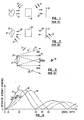
- a hologram is desired to be made of a three-dimensional diffusely reflecting object 11, for example, that object is illuminated by coherent radiation 13, usually obtained from a laser.
- coherent radiation 13 usually obtained from a laser.
- Light reflected from the object 11 in an object beam 15 may be passed directly onto a photosensitive hologram detector 17, or, more generally, is passed through an optical system 19-beforehand, and then onto the detector 17 as object beam 16.
- a reference beam 21, coherent with the object illuminating beam 13 is directed against the hologram detector 17 at a finite angle with the object information carrying beam 16.
- the reference beam 21 is usually unmodulated.
- the hologram detector 17 is then processed to record a diffraction pattern formed thereat by interference of the beams 16 and 21.
- This forms hologram 17' that is, in a second step illustrated in Figure 2, illuminated by reconstructing coherent radiation 22 in order to produce a replica 16' of the recorded object image carrying beam 16.
- This replicated wavefront 16' may, optionally, pass through an appropriate optical system to create the information carrying beam 15' on a second hologram detector 25 that is positioned therein at the location of a reconstructed real image 11' of the original object 11.
- the wavefront 15' is captured on the detector 25 by directing a reference beam 27, that is coherent with the hologram illuminating beam 22, against the holographic detector 25 at a finite angle with the beam 15'.
- Figures 1 and 2 show a rather generic, two-step hologram making process.
- the hologram resulting from appropriate processing of detector 25 is capable of reconstructing an image adjacent the surface of the hologram itself. This is termed a "focused image" hologram and is the type that is most commonly made for replicated holograms, including those used on credit cards and the like.
- an image may be focused into the hologram detector 17 by appropriate optics within the optical system 19, in order to make a hologram according to the single step of Figure 1 without having to make the second hologram of Figure 2.
- the two-step process shown in Figures 1 and 2 is preferred for quality and a large field of view.
- the hologram detector 25 is most commonly made of a photoresist material such that the interference pattern formed thereacross by interference between the beams 15' and 27 is converted into a surface relief pattern that refracts incident light into its various orders, although it is optically clear thereacross. However, this is referred to herein as "diffraction,” as is commonly used in the holographic arts.
- the first hologram 17 is often made from high resolution silver halide photographic film, in a linear region, in order to form a high quality intensity hologram.
- the surface relief hologram has many advantages for inexpensive replication since a metal master (not shown) can be made from it, and that metal master is then used to emboss thin plastic foil with the surface relief pattern These embossed replicas are usually coated with a thin film of reflective material so that a replica of the recorded wavefront is reconstructed therefrom in reflected light.
- a hologram replica 29 is illustrated, from which an image 11" is reconstructed therefrom when illuminated by white (multicolored, non-coherent) light 31.
- An observer 33 sees the best image when looking in a first order diffracted beam.
- a single such first order diffracted beam is shown in Figure 3, with a separation of colors that exists.
- the observer 33 is shown to be positioned to view the image 11" in a green portion 35 of the first order diffracted beam.
- the observer 33 can view the image in other colors, such as in a red portion 37 of the diffracted beam, or, if tilted in an opposite direction, in a blue portion 39.
- the color spectrum is generally continuous, but only three color components are being described for simplicity.
- the hologram 29 is viewable in non-coherent, white light because its image is reconstructed near the surface of the hologram and because of optical elements used in the known optical system 19 and/or 23 of the master making process shown in Figures 1 and 2.
- the most commonly used systems 19 and 23 also are designed to limit the bandwidth of the object wavefront recorded on the master hologram 25 by discarding vertical parallax and retaining horizontal parallax.
- FIGs 5 and 6 The curves of Figure 4 illustrate the known diffraction efficiency characteristics of a simple sinusoidal grating-which results with the construction of a hologram whose object is a plane wave.
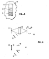
- An opaque mask 46 contains three adjacent transparent regions 47, 49 and 51.
- the region 47 is optically clear, the region 49 somewhat gray and the region 51 more gray.
- These regions are illuminated by a plane wave coherent beam 50, in Figure 6(A), and imaged by a lens system 48 onto the hologram detector 25.
- the use of a planar off-axis reference beam 52, coherent with the beam 50, forms the desired diffraction pattern.
- the mask 46 may be positioned immediately adjacent the detector 25 and both the interfering coherent wavefronts 50 and 52 passed through its regions 47, 49 and 51, as shown in Figure 6(B). In either case, the diffraction pattern so formed may be replicated as a surface relief pattern to form a replica 29, as described above.
- Figure 4 On a horizontal axis of Figure 4, which is specifically related to surface relief hologram gratings, is the depth of the groove of the grating, beginning at the left with zero depth (smooth surface).
- the vertical axis indicates the percentage of light striking the grating that is diffracted into a single first order diffracted beam. As is well known, some of the incident light is diffracted into other orders or is reflected as a zero-order beam.
- the curves of Figure 4 are Bessel functions, given the usual mathematical notation J 1 2. When white (multicolored) light strikes such a simple grating, it is diffracted into rays which are oriented according to the colors just as is illustrated in Figure 3 for the generalized hologram.
- Figure 4 illustrates exemplary characteristics of a portion of the replica 29 containing a grating made according to either Figures 6 (A) or (B), in the separate colors chosen for illustration in Figure 3.
- a curve 41 shows the intensity characteristics of the blue portion 39 of the diffracted beam.
- a curve 43 shows that characteristic for the green portion 35 of the diffracted order, and curve 45 for the red portion 37.
- the groove depth of the resulting diffraction pattern is controlled primarily by two factors.
- One factor is the intensity of the light that is recorded on the master hologram 25, and the other factor is the post-expo processing.
- the first hologram 17 made in the existing process illustrated in Figures 1 and 2 is held on a very linear portion its characteristic curve.
- the groove depth is usually increased in order to improve the amount of light that is diffracted into an image carrying first order beam. It is not unusual for groove depths to be selected for the diffraction efficiency to extend to near the peak of the curves, such as indicated at D2 for the blue curve 41.
- Gratings are generally made with groove depths at the peak of such curves in order to maximize the amount of incident light that is diffracted into a first order beam. With diffraction gratings, of course, there is not the concern for image distortion.
- a principal aspect of the present invention is the intentional making of holograms that operate well beyond the first peak of its characteristic Bessel function curve for a first order diffracted beam.
- the extremely non-linear, low, and even zero, diffraction intensity efficiency characteristics to the right of these peaks in the curves of Figure 4, avoided by traditional techniques, are intentionally utilized in order to make a hologram that cannot be exactly replicated.
- the area 47' is constructed to have a groove depth substantially that indicated at D3 in Figure 4.
- the amount of light diffracted from that area into a blue component 39 of the first order diffracted beam is zero, while there is some intensity in other colors.
- the adjacent area 49' is made to have a groove depth substantially equal to D4 indicated on Figure 4, thus having no light diffracted in the green portion 35.
- the region 51' is made to have a depth substantially equal to D5 of Figure 4, thereby having substantially no intensity diffracted into the red component 37 of the image carrying beam of Figure 3, while having some intensity that is viewable in the other color components 35 and 39.
- the effect is thus that as a hologram 29 is rotated with respect to the observer 23 about a horizontal axis (perpendicular to the surface of Figure 3), a black spot appears to move across the portion of the image containing areas 47', 49' and 51' as the diffraction beam sweeps through the colors.
- Figure 8 illustrates generally the use of such a hologram 29, attached to a carrier 53.
- the carrier 53 can be a credit card, for example, or a passport, identification card, driver's license, stock certificate, and the like.
- the purpose of the hologram 29 is to authenticate the carrier 53 and any information carried on it. By rotation of the carrier 53 above the horizontal axis, a black spot appears to move across the hologram portions 471, 49' and 51', a part of a larger image 11" .
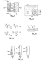
- Figure 9 shows a one typical way of copying a replicated hologram.
- the hologram 29 is illuminated by a coherent light beam 55 to form a diffracted beam 57 that is captured on an intermediate holographic detector 59 by use of an off-axis reference beam 61.
- Processed hologram 59' is then played back by a coherent reconstruction beam 63 to record on another hologram detector 65 a first order diffracted beam 67.
- the detector 65 is positioned to coincide with the image 69 reconstructed in the first order beam 67 so that it will be a replica of the focused image hologram 29. That image is recorded by a coherent, off-axis reference beam 71.
- the known copying technique of Figure 9 is generally preferred since only a single diffracted order of light is captured on the hologram detector 59 of Figure 9(A) and 65 of Figure 9(B).
- a different technique, termed contact copying, is illustrated in Figure 10 and is somewhat simpler.
- the hologram 29 is placed immediately adjacent to a holographic copy detector 73.
- a coherent light beam 75 is then passed through the hologram 29. All of the orders diffracted by the hologram 29 are thus captured on the detector 73, along with the zero diffracted order (that is, the undiffracted portion of the light beam 75 passes directly through the hologram 29). All of these diffracted orders interfere among themselves to create extra and unwanted image terms.
- the zero order beam which serves as the reference, is not of uniform intensity across it by the time it strikes the detector 73. Therefore, images reconstructed from a contact copy are generally of poorer quality than those made of the technique of Figure 9.
- the copy hologram detector simply receives no light in the object beam from the region 47', and so the replica illustrated in Figure 11(A) is smooth in the corresponding area. Similarly, Figure 11(B) shows a replica made with green monochromatic light, and Figure 11(C) a replica in red. In any of these cases, a portion of the information on the original hologram is not copied, so the reconstructed image will not be the same. In this specific example, the spot will not move as a hologram is tilted about a horizontal axis.
- Figure 12 shows in a different, more general way, why the image reconstructed from the copy hologram will be different from that originally recorded on the original hologram.
- Each of the original and copied holograms are indicated by a box in Figure 12 with a given input/output transfer function.
- the original optical signal "s" is recorded on the original hologram.
- the first order diffracted signal reconstructed from it is, which is then recorded on the copy hologram, where "C" is a constant, and ⁇ 2 is the copy wavelength.
- the first order signal reconstructed at wavelength ⁇ 3 from the copy is, where "k" is a constant.
- the amplitude of the first order diffracted light varies in a manner different than that of the original hologram. That is, in general, as the wavelength ⁇ 3 is varied.
- the wavelength ⁇ 2 is fixed in the recording step of the copy. This effect is particularly noticeable when extremely non-linear portions of J in the original hologram are used.
- FIG. 13 another first order Bessel function 81 is shown, along with a second order function 83. That is, the curve 81 shows the relative intensity of light diffracted into a first order beam, and the curve 83 that diffracted into a second order beam.
- the second order diffraction was not considered above, since it was assumed that the image was being viewed in only a first order diffracted beam. But the existence of a second order diffracted beam, in which a useful reconstruction of an image may also be present, can also be used to implement the present invention.
- a master hologram can be made with a particular geometry so second, and even higher, diffracted orders are easily viewable, as well as the first order.
- the first order curve 81 has a zero diffraction efficiency at a groove depth dl
- the second order beam a zero diffraction efficiency at a different and deeper groove depth d2.
- this allows operation in those zero regions of the curves to produce the same result when rotating a surface relief hologram 85 ( Figure 14) about a horizontal axis.
- An observer alternately views an image 89 in a first order diffracted beam 91 and then in a second order diffracted beam 93.
- operation in extreme non-linear regions of the curves of Figure 13 also brings about the desired results.
- a second way to make a copy includes individually recording, one at a time, all measurable orders diffracted from the hologram 85 onto a linear photosensitive copy detector.
- the laborious multiple holograms are recorded with low intensity in order to operate on a linear portion of the copy detector's characteristic curve and also to assure that extra terms of higher order are to be avoided.
- the resulting images reconstructed from the copy are thus very dim. Even so, specific changes in the original that occur with a single wavelength will not be faithfully copied, for the reasons discussed above with respect to Figures 4-11.
Abstract
Description
- This invention relates generally to diffraction gratings and holograms, especially those designed for use as security devices to authenticate documents or objects to which they are attached.
- Holograms are becoming widely used on credit cards as security devices to authenticate genuine cards. Similar use of holograms is being made, or proposed to be made, in authenticating certificates of various kinds, as seals for containers to restrict unauthorized entry, and similar applications. Currently, such holograms are embossed onto thin plastic with a reflective layer added, the embossing hologram originally being made in an optical laboratory with laser equipment. The plastic replicated holograms are made of very thin material and attached to the credit card, or other device being authenticated, in a manner that an attempted removal of the hologram destroys it. This reduces the likelihood that holograms for counterfeit documents can be removed from other expired or unused cards or documents.
- Holograms which reconstruct images of objects are a preferred form of diffraction grating for security applications because they are harder to make. The specialized skills and extensive equipment that is required to make a hologram create a significant barrier for counterfeiters who attempt to make original holograms from an object scene that resembles that of the security hologram to be simulated.
- Effort has been directed to making security holograms in which the object scene is chosen such that any copies that might be made by counterfeiters will not look exactly like the original. However, it is difficult to make such a security hologram from which a copy of it can readily be distinguished by the usual observer from the original. Therefore, it is a primary object of the present invention to provide a diffraction grating and hologram, and methods of making them, from which unauthorized copies thereof are more readily apparent.
- This and additional objects are accomplished by the various aspects of the present invention, wherein, briefly, a diffraction grating, or hologram, is made in a way that an image reconstructed from a copy is significantly different from that reconstructed from the original, so copies can easily be detected. One technique in making the original security grating, or hologram, according to the present invention is to do so in a manner that the image changes when the hologram, which is illuminated in polychromatic light, is tilted with respect to the viewer and thus viewed in the different colors of diffracted light. This security hologram is also made so that copies from it do not show this changing image. For example, the original grating or hologram can be made so that at least one dark region moves across the diffracted light pattern or image as the grating or hologram is tilted. A copy made in monochromatic light will, when reconstructed in white light, show a fixed dark spot as the grating or hologram is tilted, rather than a moving one, thereby being easily detectable as a counterfeit.
- A way of constructing such a security hologram, according to the present invention, is to take advantage of the fact that the diffraction intensity characteristics of a grating or hologram are not a linear function of the light intensity pattern recorded on it. The prevalent current approach is to operate on a linear enough portion of such a characteristic curve that reconstructed image degradations are kept within desired limits. But the technique of the present invention intentionally operates on non-linear portions of a grating or hologram characteristic curve so that an image wavefront reconstructed from the copy is much different than that reconstructed from the grating or hologram being copied for all but a narrow range of reconstruction wavelengths.
- Additional objects, advantages and features of the various aspects of the present invention will become apparent from the following description of its preferred embodiments, which description should be taken in conjunction with the accompanying drawings.
-
- Figures 1 and 2 show, as background, general existing techniques for making a master optical hologram;
- Figure 3 illustrates the viewing characteristics of a typical existing type of hologram that is replicated from that made according to the method shown in Figures 1 and 2;
- Figure 4 illustrates characteristic curves of a diffraction grating or hologram;
- Figures 5 and 6 show an example of making a diffraction pattern using characteristics illustrated in the curves of Figure 4;
- Figure 7 shows an example of a diffraction pattern that was made according to the method of Figures 5 and 6; 1
- Figure 8 illustrates one use of such a diffraction pattern;
- Figures 9 and 10 show two typical methods that counterfeiters might use for copying a hologram from a credit card and the like;
- Figure 11 shows the diffraction pattern of Figure 7 that is obtained on such a copy,
- Figure 12 illustrates schematically the effect of the diffraction characteristics of an original and copy hologram;
- Figure 13 shows additional characteristic curves of a diffraction grating or hologram; and
- Figure 14 illustrates the reconstruction of an image from a hologram made according to yet another aspect of the present invention.
- The embodiment described herein is a surface relief hologram. In this description, a diffraction grating is considered to be a special case of a hologram. Both are formed by interfering two coherent light beams at a photosensitive surface. The result in both is a surface that diffracts light into one or more diffracted orders of varying colors when viewed in white light. The difference for a hologram is that, during its construction, one of the coherent beams used to make it can either pass through, or be reflected from, an object scene before striking the photosensitive surface. Such a hologram thus forms in its diffracted beams an image of that object scene. A diffraction grating is made from a controlled wavefront, such as a plane wave, so does not reconstruct an image of a complex object. What is viewed in a diffracted beam from a diffraction grating is either a uniform wavefront or a simply varying one. Although specific diffraction grating security techniques are described herein with respect to the figures, it will be understood that the more complex holographic techniques are also within the scope of this application.
- Referring initially to Figures 1-3, well-known holographic techniques, and the resulting holograms, wifl be generally described as background. If a hologram is desired to be made of a three-dimensional diffusely reflecting object 11, for example, that object is illuminated by coherent radiation 13, usually obtained from a laser. Light reflected from the object 11 in an
object beam 15 may be passed directly onto aphotosensitive hologram detector 17, or, more generally, is passed through an optical system 19-beforehand, and then onto thedetector 17 asobject beam 16. In either case, areference beam 21, coherent with the object illuminating beam 13, is directed against thehologram detector 17 at a finite angle with the objectinformation carrying beam 16. Thereference beam 21 is usually unmodulated. - For a simple holographic grating, neither the object wave 11 nor the
optical system 19 need be used. Instead, an unmodulated plane wave is used in place ofobject wave 16. - The
hologram detector 17 is then processed to record a diffraction pattern formed thereat by interference of thebeams coherent radiation 22 in order to produce a replica 16' of the recorded objectimage carrying beam 16. This replicated wavefront 16' may, optionally, pass through an appropriate optical system to create the information carrying beam 15' on asecond hologram detector 25 that is positioned therein at the location of a reconstructed real image 11' of the original object 11. The wavefront 15' is captured on thedetector 25 by directing a reference beam 27, that is coherent with the hologramilluminating beam 22, against theholographic detector 25 at a finite angle with the beam 15'. - Figures 1 and 2 show a rather generic, two-step hologram making process. The hologram resulting from appropriate processing of
detector 25 is capable of reconstructing an image adjacent the surface of the hologram itself. This is termed a "focused image" hologram and is the type that is most commonly made for replicated holograms, including those used on credit cards and the like. Alternatively, an image may be focused into thehologram detector 17 by appropriate optics within theoptical system 19, in order to make a hologram according to the single step of Figure 1 without having to make the second hologram of Figure 2. But the two-step process shown in Figures 1 and 2 is preferred for quality and a large field of view. - The
hologram detector 25 is most commonly made of a photoresist material such that the interference pattern formed thereacross by interference between the beams 15' and 27 is converted into a surface relief pattern that refracts incident light into its various orders, although it is optically clear thereacross. However, this is referred to herein as "diffraction," as is commonly used in the holographic arts. Thefirst hologram 17 is often made from high resolution silver halide photographic film, in a linear region, in order to form a high quality intensity hologram. - The surface relief hologram has many advantages for inexpensive replication since a metal master (not shown) can be made from it, and that metal master is then used to emboss thin plastic foil with the surface relief pattern These embossed replicas are usually coated with a thin film of reflective material so that a replica of the recorded wavefront is reconstructed therefrom in reflected light.
- Referring to Figure 3, suαh a
hologram replica 29 is illustrated, from which an image 11" is reconstructed therefrom when illuminated by white (multicolored, non-coherent)light 31. Anobserver 33 sees the best image when looking in a first order diffracted beam. A single such first order diffracted beam is shown in Figure 3, with a separation of colors that exists. Theobserver 33 is shown to be positioned to view the image 11" in agreen portion 35 of the first order diffracted beam. By tilting the hologram about an axis perpendicular to the paper, theobserver 33 can view the image in other colors, such as in ared portion 37 of the diffracted beam, or, if tilted in an opposite direction, in ablue portion 39. The color spectrum is generally continuous, but only three color components are being described for simplicity. - The
hologram 29 is viewable in non-coherent, white light because its image is reconstructed near the surface of the hologram and because of optical elements used in the knownoptical system 19 and/or 23 of the master making process shown in Figures 1 and 2. The most commonly usedsystems master hologram 25 by discarding vertical parallax and retaining horizontal parallax. - The curves of Figure 4 illustrate the known diffraction efficiency characteristics of a simple sinusoidal grating-which results with the construction of a hologram whose object is a plane wave. The making of a simple security grating that takes advantage of these characteristics is illustrated in Figures 5 and 6. An
opaque mask 46 contains three adjacenttransparent regions region 47 is optically clear, theregion 49 somewhat gray and theregion 51 more gray. These regions are illuminated by a plane wavecoherent beam 50, in Figure 6(A), and imaged by alens system 48 onto thehologram detector 25. The use of a planar off-axis reference beam 52, coherent with thebeam 50, forms the desired diffraction pattern. - As a variation of the technique of Figure 6(A), the
mask 46 may be positioned immediately adjacent thedetector 25 and both the interferingcoherent wavefronts regions replica 29, as described above. - On a horizontal axis of Figure 4, which is specifically related to surface relief hologram gratings, is the depth of the groove of the grating, beginning at the left with zero depth (smooth surface). The vertical axis indicates the percentage of light striking the grating that is diffracted into a single first order diffracted beam. As is well known, some of the incident light is diffracted into other orders or is reflected as a zero-order beam. Also, as is well known, the curves of Figure 4 are Bessel functions, given the usual mathematical notation J1 2. When white (multicolored) light strikes such a simple grating, it is diffracted into rays which are oriented according to the colors just as is illustrated in Figure 3 for the generalized hologram.
- Figure 4 illustrates exemplary characteristics of a portion of the
replica 29 containing a grating made according to either Figures 6 (A) or (B), in the separate colors chosen for illustration in Figure 3. Acurve 41 shows the intensity characteristics of theblue portion 39 of the diffracted beam. Similarly, acurve 43 shows that characteristic for thegreen portion 35 of the diffracted order, andcurve 45 for thered portion 37. - The groove depth of the resulting diffraction pattern is controlled primarily by two factors. One factor is the intensity of the light that is recorded on the
master hologram 25, and the other factor is the post- exposure processing. For a general hologram, thefirst hologram 17 made in the existing process illustrated in Figures 1 and 2, is held on a very linear portion its characteristic curve. When thesecond hologram 25 is made, the groove depth is usually increased in order to improve the amount of light that is diffracted into an image carrying first order beam. It is not unusual for groove depths to be selected for the diffraction efficiency to extend to near the peak of the curves, such as indicated at D2 for theblue curve 41. Some distortion is encountered when operating in the region that includes slightly non-linear portions, but this does not significantly degrade the quality of most focused image holograms. Gratings are generally made with groove depths at the peak of such curves in order to maximize the amount of incident light that is diffracted into a first order beam. With diffraction gratings, of course, there is not the concern for image distortion. - A principal aspect of the present invention is the intentional making of holograms that operate well beyond the first peak of its characteristic Bessel function curve for a first order diffracted beam. The extremely non-linear, low, and even zero, diffraction intensity efficiency characteristics to the right of these peaks in the curves of Figure 4, avoided by traditional techniques, are intentionally utilized in order to make a hologram that cannot be exactly replicated.
- As a specific example of the inventive technique, consider a part of a
hologram 29 of Figure 7 having three adjacent grating regions 47', 49' and 51' that have been made by one of the techniques of Figure 6. In this illustrative example, the area 47' is constructed to have a groove depth substantially that indicated at D3 in Figure 4. As can be seen, the amount of light diffracted from that area into ablue component 39 of the first order diffracted beam is zero, while there is some intensity in other colors. Similarly, the adjacent area 49' is made to have a groove depth substantially equal to D4 indicated on Figure 4, thus having no light diffracted in thegreen portion 35. Lastly, for this illustration, the region 51' is made to have a depth substantially equal to D5 of Figure 4, thereby having substantially no intensity diffracted into thered component 37 of the image carrying beam of Figure 3, while having some intensity that is viewable in theother color components hologram 29 is rotated with respect to theobserver 23 about a horizontal axis (perpendicular to the surface of Figure 3), a black spot appears to move across the portion of the image containing areas 47', 49' and 51' as the diffraction beam sweeps through the colors. - Figure 8 illustrates generally the use of such a
hologram 29, attached to acarrier 53. Thecarrier 53 can be a credit card, for example, or a passport, identification card, driver's license, stock certificate, and the like. The purpose of thehologram 29 is to authenticate thecarrier 53 and any information carried on it. By rotation of thecarrier 53 above the horizontal axis, a black spot appears to move across the hologram portions 471, 49' and 51', a part of a larger image 11" . - The reason that the
non-conventional hologram 29 is useful is that a copy made in monochromatic light from it will not reproduce the moving spot. Therefore, copies can be readily identified. This is explained with respect to Figures 9-11. Figure 9 shows a one typical way of copying a replicated hologram. Thehologram 29 is illuminated by a coherent light beam 55 to form a diffractedbeam 57 that is captured on an intermediateholographic detector 59 by use of an off-axis reference beam 61. Processed hologram 59' is then played back by a coherent reconstruction beam 63 to record on another hologram detector 65 a first order diffracted beam 67. Thedetector 65 is positioned to coincide with theimage 69 reconstructed in the first order beam 67 so that it will be a replica of thefocused image hologram 29. That image is recorded by a coherent, off-axis reference beam 71. - The known copying technique of Figure 9 is generally preferred since only a single diffracted order of light is captured on the
hologram detector 59 of Figure 9(A) and 65 of Figure 9(B). A different technique, termed contact copying, is illustrated in Figure 10 and is somewhat simpler. Thehologram 29 is placed immediately adjacent to aholographic copy detector 73. Acoherent light beam 75 is then passed through thehologram 29. All of the orders diffracted by thehologram 29 are thus captured on thedetector 73, along with the zero diffracted order (that is, the undiffracted portion of thelight beam 75 passes directly through the hologram 29). All of these diffracted orders interfere among themselves to create extra and unwanted image terms. Also, the zero order beam, which serves as the reference, is not of uniform intensity across it by the time it strikes thedetector 73. Therefore, images reconstructed from a contact copy are generally of poorer quality than those made of the technique of Figure 9. - It will be recognized that both Figures 9 and 10 assume that the
hologram 29 allows reconstructing light to pass through it. With a metallized, plastic embossed hologram of the type now used for security applications, this first requires neutralization or removal of the reflective coating. However, the techniques of Figures 9 and 10 can be used to make a copy from reflective holograms as well. - This discussion of copying is included herein for the purpose of illustrating the additional security features of the
hologram 29. This is best illustrated by reference to Figure 11 wherein a cross-section of a copy hologram at the portions of the image corresponding to areas 47', 49' and 51' of the original hologram are illustrated as 47" , 49" and 51" . Figure 11(A) shows such a replica made in blue coherent light. Only monochromatic light can be used in making copies of the hologram if undesirable distortion or blurring is to be prevented. The result of using this standard copy technique on thehologram 29 in blue light means that the region 47' of thehologram 29 that had zero diffraction intensity efficiency in blue light is not recorded at all. The copy hologram detector simply receives no light in the object beam from the region 47', and so the replica illustrated in Figure 11(A) is smooth in the corresponding area. Similarly, Figure 11(B) shows a replica made with green monochromatic light, and Figure 11(C) a replica in red. In any of these cases, a portion of the information on the original hologram is not copied, so the reconstructed image will not be the same. In this specific example, the spot will not move as a hologram is tilted about a horizontal axis. - Figure 12 shows in a different, more general way, why the image reconstructed from the copy hologram will be different from that originally recorded on the original hologram. Each of the original and copied holograms are indicated by a box in Figure 12 with a given input/output transfer function. The original optical signal "s" is recorded on the original hologram. The first order diffracted signal reconstructed from it is,


- AS discussed above, it is a usual goal in making a surface phase hologram to operate on a linear portion of the Bessel function curve. But in the present invention, the original hologram is intentionally made in an extremely non-linear portion of its characteristic curve so the signal recorded on the copy hologram is the original signal with a non-linear transfer function superimposed on it. Therefore, the optical signal reconstructed from the copy will not be a faithful reproduction of the original optical signal recorded.
- Referring to Figure 13, another first
order Bessel function 81 is shown, along with asecond order function 83. That is, thecurve 81 shows the relative intensity of light diffracted into a first order beam, and thecurve 83 that diffracted into a second order beam. The second order diffraction was not considered above, since it was assumed that the image was being viewed in only a first order diffracted beam. But the existence of a second order diffracted beam, in which a useful reconstruction of an image may also be present, can also be used to implement the present invention. A master hologram can be made with a particular geometry so second, and even higher, diffracted orders are easily viewable, as well as the first order. It will be noticed from Figure 13 that thefirst order curve 81 has a zero diffraction efficiency at a groove depth dl, and the second order beam a zero diffraction efficiency at a different and deeper groove depth d2. For the same reasons stated above, therefore, this allows operation in those zero regions of the curves to produce the same result when rotating a surface relief hologram 85 (Figure 14) about a horizontal axis. An observer alternately views an image 89 in a first order diffracted beam 91 and then in a second order diffractedbeam 93. Alternative to operating in a region including zero diffraction efficiency, operation in extreme non-linear regions of the curves of Figure 13 also brings about the desired results. - While a hologram made in accordance with the techniques discussed above with respect to Figures 13 and 14 cannot be copied by one of the methods of Figures 9 or 10 in a manner to faithfully mimic the patterns in the original hologram as the reconstructing wavelength is changed, it is possible to make a copy in a different way that closely mimics the patterns of the original at a single wavelength. This, however, is extremely difficult to accomplish, thus still providing a hologram with good security. For example, if all the orders are collected and used simultaneously as the object beam of the copy hologram, additional cross-product terms will result. This causes the relative intensities of the observed orders in the copy to be different than that of the original. A second way to make a copy includes individually recording, one at a time, all measurable orders diffracted from the hologram 85 onto a linear photosensitive copy detector. The laborious multiple holograms are recorded with low intensity in order to operate on a linear portion of the copy detector's characteristic curve and also to assure that extra terms of higher order are to be avoided. The resulting images reconstructed from the copy are thus very dim. Even so, specific changes in the original that occur with a single wavelength will not be faithfully copied, for the reasons discussed above with respect to Figures 4-11.
- Although the various aspects of the present invention have been described with respect to its preferred embodiments, it will be understood that the invention is entitled to protection within the full scope of the appended claims. Specifically, it should be understood that the method is not limited to holographic diffraction gratings but can be used with much more complex holographic imagery.
Claims (18)
Applications Claiming Priority (2)
| Application Number | Priority Date | Filing Date | Title |
|---|---|---|---|
| US864193 | 1986-05-16 | ||
| US06/864,193 US4832445A (en) | 1986-05-16 | 1986-05-16 | Security diffraction devices difficult to exactly duplicate |
Publications (2)
| Publication Number | Publication Date |
|---|---|
| EP0247471A2 true EP0247471A2 (en) | 1987-12-02 |
| EP0247471A3 EP0247471A3 (en) | 1988-10-05 |
Family
ID=25342720
Family Applications (1)
| Application Number | Title | Priority Date | Filing Date |
|---|---|---|---|
| EP87107146A Withdrawn EP0247471A3 (en) | 1986-05-16 | 1987-05-18 | Security diffraction devices difficult to exactly duplicate |
Country Status (8)
| Country | Link |
|---|---|
| US (1) | US4832445A (en) |
| EP (1) | EP0247471A3 (en) |
| JP (1) | JPS63503331A (en) |
| KR (1) | KR880701386A (en) |
| AU (1) | AU595892B2 (en) |
| CA (1) | CA1286132C (en) |
| DK (1) | DK7988A (en) |
| WO (1) | WO1987007034A1 (en) |
Cited By (8)
| Publication number | Priority date | Publication date | Assignee | Title |
|---|---|---|---|---|
| EP0337921A2 (en) * | 1988-04-09 | 1989-10-18 | Ewald Rollnik | Assembly for recognizing and securing objects and its application |
| EP0449893A1 (en) * | 1988-12-19 | 1991-10-09 | Australia Reserve Bank | Diffraction grating. |
| WO1993025941A1 (en) * | 1992-06-08 | 1993-12-23 | Istituto Poligrafico E Zecca Dello Stato | Holograms having a standard reference colour |
| WO1995023986A1 (en) * | 1994-03-03 | 1995-09-08 | Hologram Industries S.A. | Method for the production of an optically variable image |
| WO1996035191A2 (en) * | 1995-05-06 | 1996-11-07 | Leonhard Kurz Gmbh & Co. | Optically diffractive structure |
| WO1997027504A1 (en) * | 1996-01-26 | 1997-07-31 | Landis & Gyr Technology Innovation Ag | Surface pattern |
| EP0715232A3 (en) * | 1994-12-02 | 1997-10-22 | Bundesdruckerei Gmbh | Master hologram for the fabrication of copy-protected holograms |
| US6369947B1 (en) | 1996-12-12 | 2002-04-09 | Ovd Kinegram Ag | Surface pattern |
Families Citing this family (42)
| Publication number | Priority date | Publication date | Assignee | Title |
|---|---|---|---|---|
| EP0375833B1 (en) * | 1988-12-12 | 1993-02-10 | Landis & Gyr Technology Innovation AG | Optically variable planar pattern |
| DE3843076A1 (en) * | 1988-12-21 | 1990-07-05 | Gao Ges Automation Org | SECURITY ELEMENT TO PROTECT DOCUMENTS AGAINST UNAUTHORIZED REPRODUCTION |
| EP0490923B1 (en) * | 1989-09-04 | 1999-02-03 | Commonwealth Scientific And Industrial Research Organisation | Diffraction grating and method of manufacture |
| US5428479A (en) * | 1989-09-04 | 1995-06-27 | Commonwealth Scientific And Industrial Research Organisation | Diffraction grating and method of manufacture |
| CA2060057C (en) * | 1991-01-29 | 1997-12-16 | Susumu Takahashi | Display having diffraction grating pattern |
| US5634669A (en) * | 1991-04-16 | 1997-06-03 | American Bank Note Holographics, Inc. | Holographic check authentication article |
| US5458713A (en) * | 1991-09-25 | 1995-10-17 | Gao Gesellschaft Fuer Automation Und Organisation Mbh | Multilayer data carrier and a method for producing it |
| WO1993018419A1 (en) * | 1992-03-12 | 1993-09-16 | Commonwealth Scientific And Industrial Research Organisation | Security diffraction grating with special optical effects |
| US5331443A (en) * | 1992-07-31 | 1994-07-19 | Crown Roll Leaf, Inc. | Laser engraved verification hologram and associated methods |
| US5410397A (en) * | 1993-02-16 | 1995-04-25 | The United States Of America As Represented By The United States Department Of Energy | Method and apparatus for holographic wavefront diagnostics |
| EP0712500B1 (en) * | 1993-08-06 | 2001-10-31 | Commonwealth Scientific And Industrial Research Organisation | A diffractive device |
| TW265421B (en) * | 1993-11-23 | 1995-12-11 | Commw Scient Ind Res Org | |
| AUPM382994A0 (en) * | 1994-02-14 | 1994-03-10 | Commonwealth Scientific And Industrial Research Organisation | Diffractive device with enhanced anti-copying protection |
| US5593017A (en) * | 1994-03-18 | 1997-01-14 | Environmental Products Corporation | Method and apparatus for identifying information contained in surface deviations |
| US5464690A (en) * | 1994-04-04 | 1995-11-07 | Novavision, Inc. | Holographic document and method for forming |
| CN1174611A (en) * | 1994-09-05 | 1998-02-25 | 米高技术有限公司 | Diffraction surfaces and method for manufacture thereof |
| EP0712012A1 (en) * | 1994-11-09 | 1996-05-15 | International Business Machines Corporation | Authentication label and authenticating pattern incorporating diffracting structure and method of fabricating them |
| JP3469038B2 (en) * | 1996-06-10 | 2003-11-25 | ローレルバンクマシン株式会社 | Bill validator |
| US5986781A (en) | 1996-10-28 | 1999-11-16 | Pacific Holographics, Inc. | Apparatus and method for generating diffractive element using liquid crystal display |
| PT919961E (en) * | 1997-11-27 | 2003-10-31 | Bundesdruckerei Gmbh | DOCUMENT SAFETY ELEMENT AND PROCESS FOR THEIR MANUFACTURE |
| US6088140A (en) * | 1998-02-05 | 2000-07-11 | Zebra Imaging, Inc. | Segmented display system for large, continuous autostereoscopic images |
| JP4689825B2 (en) * | 1998-08-26 | 2011-05-25 | センサーズ・フォー・メデセン・アンド・サイエンス・インコーポレーテッド | Optical detector |
| AU2004201752B2 (en) * | 1998-08-26 | 2007-01-11 | Sensors For Medicine And Science, Inc. | Optical-based sensing devices |
| US6527754B1 (en) * | 1998-12-07 | 2003-03-04 | Std Manufacturing, Inc. | Implantable vascular access device |
| EP1666987A2 (en) * | 1998-12-30 | 2006-06-07 | Glud & Marstrand A/S | A method for replicating a surface relief and an article for holding a surface relief |
| FR2796184B1 (en) * | 1999-07-09 | 2001-11-02 | Thomson Csf | SECURE DOCUMENT, MANUFACTURING SYSTEM, AND SYSTEM FOR READING THE DOCUMENT |
| LT4842B (en) * | 1999-12-10 | 2001-09-25 | Uab "Geola" | Universal digital holographic printer and method |
| JP4676124B2 (en) | 2000-04-15 | 2011-04-27 | オーファオデー キネグラム アーゲー | Surface layer pattern |
| US6638386B2 (en) | 2000-04-19 | 2003-10-28 | Novavision, Inc. | Method for making holographic foil |
| US6497778B1 (en) | 2000-04-19 | 2002-12-24 | Novavision, Inc. | Method for making holographic foil |
| US6730442B1 (en) * | 2000-05-24 | 2004-05-04 | Science Applications International Corporation | System and method for replicating volume holograms |
| DE10054503B4 (en) * | 2000-11-03 | 2005-02-03 | Ovd Kinegram Ag | Light diffractive binary lattice structure and security element with such a lattice structure |
| US6493014B2 (en) | 2000-12-22 | 2002-12-10 | Impress Systems | Optical security device printing system |
| KR20020069326A (en) * | 2001-02-24 | 2002-08-30 | 학교법인 호서학원 | Visible Watermarking System Using Stereogram. |
| GB0124807D0 (en) * | 2001-10-16 | 2001-12-05 | Geola Technologies Ltd | Fast 2-step digital holographic printer |
| GB0202139D0 (en) * | 2002-01-30 | 2002-03-20 | Xyz Imaging Inc | Methods concerning the preparation of digital data required in holographic printing machines |
| DK1494859T3 (en) * | 2002-03-27 | 2011-09-26 | Joseph B Schutte Iii | Combined flexographic and intaglio printing press and control system thereto |
| CH697447B1 (en) * | 2003-12-23 | 2008-10-15 | 3D Ag | Substrate's i.e. embossing matrix, surface structure producing method for e.g. manufacturing decorative pattern, involves applying surface reliefs, and forming impression of substrate before formation of production unit |
| US7267280B2 (en) * | 2004-03-01 | 2007-09-11 | International Barcode Coporation | Diffractive optical variable image including barcode |
| US20050273434A1 (en) * | 2004-04-18 | 2005-12-08 | Allen Lubow | System and method for managing security in a supply chain |
| GB0608321D0 (en) * | 2006-04-27 | 2006-06-07 | Geola Technologies Ltd | A fast digital holographic printer & copier |
| WO2008154541A1 (en) * | 2007-06-11 | 2008-12-18 | Affyrmx, Llc | Product authentication |
Citations (4)
| Publication number | Priority date | Publication date | Assignee | Title |
|---|---|---|---|---|
| US4129382A (en) * | 1975-08-14 | 1978-12-12 | Landis & Gyr | Method and apparatus for storing and reading authenticating information |
| EP0012375A2 (en) * | 1978-12-14 | 1980-06-25 | Hoechst Aktiengesellschaft | Identification card |
| GB2116908A (en) * | 1982-03-18 | 1983-10-05 | Jeffrey Blyth | Hologram identification device |
| EP0105099B1 (en) * | 1982-10-04 | 1986-01-29 | LGZ LANDIS & GYR ZUG AG | Document with diffractive security pattern |
Family Cites Families (8)
| Publication number | Priority date | Publication date | Assignee | Title |
|---|---|---|---|---|
| DE105099C (en) * | ||||
| DE12375C (en) * | H. ST. PURK IS in Stroud (Gloucester) und W. G. ETCHELLES in Huddersfield (York, England) | New to scissors for metal, stuff and other material | ||
| US3633989A (en) * | 1969-10-21 | 1972-01-11 | Polaroid Corp | Method for making reduced bandwidth holograms |
| US3957354A (en) * | 1975-02-03 | 1976-05-18 | Rca Corporation | Diffractive subtractive color filtering technique |
| US4417784A (en) * | 1981-02-19 | 1983-11-29 | Rca Corporation | Multiple image encoding using surface relief structures as authenticating device for sheet-material authenticated item |
| US4892385A (en) * | 1981-02-19 | 1990-01-09 | General Electric Company | Sheet-material authenticated item with reflective-diffractive authenticating device |
| US4484797A (en) * | 1981-07-20 | 1984-11-27 | Rca Corporation | Diffractive subtractive color filter responsive to angle of incidence of polychromatic illuminating light |
| US4576439A (en) * | 1982-09-15 | 1986-03-18 | Rca Corporation | Reflective diffractive authenticating device |
-
1986
- 1986-05-16 US US06/864,193 patent/US4832445A/en not_active Expired - Fee Related
-
1987
- 1987-05-18 WO PCT/US1987/001175 patent/WO1987007034A1/en unknown
- 1987-05-18 AU AU74804/87A patent/AU595892B2/en not_active Ceased
- 1987-05-18 EP EP87107146A patent/EP0247471A3/en not_active Withdrawn
- 1987-05-18 JP JP62503216A patent/JPS63503331A/en active Pending
- 1987-05-18 KR KR1019870701270A patent/KR880701386A/en not_active Application Discontinuation
- 1987-05-19 CA CA000537397A patent/CA1286132C/en not_active Expired - Fee Related
-
1988
- 1988-01-08 DK DK007988A patent/DK7988A/en not_active Application Discontinuation
Patent Citations (4)
| Publication number | Priority date | Publication date | Assignee | Title |
|---|---|---|---|---|
| US4129382A (en) * | 1975-08-14 | 1978-12-12 | Landis & Gyr | Method and apparatus for storing and reading authenticating information |
| EP0012375A2 (en) * | 1978-12-14 | 1980-06-25 | Hoechst Aktiengesellschaft | Identification card |
| GB2116908A (en) * | 1982-03-18 | 1983-10-05 | Jeffrey Blyth | Hologram identification device |
| EP0105099B1 (en) * | 1982-10-04 | 1986-01-29 | LGZ LANDIS & GYR ZUG AG | Document with diffractive security pattern |
Non-Patent Citations (3)
| Title |
|---|
| APPLIED OPTICS, vol. 9, no. 12, December 1970, pages 2720-2724, New York, US; M.J. BEESLEY et al.: "The use of photoresist as a holographic recording medium" * |
| JOURNAL OF IMAGING TECHNOLOGY, vol. 10, no. 3, June 1984, pages 105-108, Society of Photographic Scientists and Engineers; H. WERLICH et al.: "Fabrication of high efficiency surface relief holograms" * |
| P. HARIHARAN.: "Optical holography", 1984, pages 1-3,120-124, Cambridge University Press, London, GB; * |
Cited By (16)
| Publication number | Priority date | Publication date | Assignee | Title |
|---|---|---|---|---|
| EP0337921A2 (en) * | 1988-04-09 | 1989-10-18 | Ewald Rollnik | Assembly for recognizing and securing objects and its application |
| EP0337921A3 (en) * | 1988-04-09 | 1990-12-05 | Ewald Rollnik | Assembly for recognizing and securing objects and its application |
| EP0449893A1 (en) * | 1988-12-19 | 1991-10-09 | Australia Reserve Bank | Diffraction grating. |
| EP0449893A4 (en) * | 1988-12-19 | 1992-03-11 | Reserve Bank Of Australia | Diffraction grating |
| US5812287A (en) * | 1992-06-08 | 1998-09-22 | Istituto Poligrafico E Zecca Dello Stato | Holograms having a standard reference color |
| AU674521B2 (en) * | 1992-06-08 | 1997-01-02 | Istituto Poligrafico E Zecca Dello Stato | Holograms having a standard reference colour |
| WO1993025941A1 (en) * | 1992-06-08 | 1993-12-23 | Istituto Poligrafico E Zecca Dello Stato | Holograms having a standard reference colour |
| WO1995023986A1 (en) * | 1994-03-03 | 1995-09-08 | Hologram Industries S.A. | Method for the production of an optically variable image |
| US5808776A (en) * | 1994-03-03 | 1998-09-15 | Hologram Industries, S.A. | Process for realization of an optically variable image |
| EP0715232A3 (en) * | 1994-12-02 | 1997-10-22 | Bundesdruckerei Gmbh | Master hologram for the fabrication of copy-protected holograms |
| WO1996035191A2 (en) * | 1995-05-06 | 1996-11-07 | Leonhard Kurz Gmbh & Co. | Optically diffractive structure |
| WO1996035191A3 (en) * | 1995-05-06 | 1997-02-13 | Kurz Leonhard Fa | Optically diffractive structure |
| US6271967B1 (en) * | 1995-05-06 | 2001-08-07 | Leonard Kurz Gmbh & Co. | Optically diffractive structure |
| WO1997027504A1 (en) * | 1996-01-26 | 1997-07-31 | Landis & Gyr Technology Innovation Ag | Surface pattern |
| US6369947B1 (en) | 1996-12-12 | 2002-04-09 | Ovd Kinegram Ag | Surface pattern |
| EP0992020B1 (en) * | 1996-12-12 | 2003-03-19 | OVD Kinegram AG | Surface pattern |
Also Published As
| Publication number | Publication date |
|---|---|
| CA1286132C (en) | 1991-07-16 |
| AU7480487A (en) | 1987-12-01 |
| DK7988D0 (en) | 1988-01-08 |
| US4832445A (en) | 1989-05-23 |
| EP0247471A3 (en) | 1988-10-05 |
| AU595892B2 (en) | 1990-04-12 |
| WO1987007034A1 (en) | 1987-11-19 |
| JPS63503331A (en) | 1988-12-02 |
| DK7988A (en) | 1988-01-08 |
| KR880701386A (en) | 1988-07-26 |
Similar Documents
| Publication | Publication Date | Title |
|---|---|---|
| US4832445A (en) | Security diffraction devices difficult to exactly duplicate | |
| US6351537B1 (en) | Verifiable holographic article | |
| EP0064067B1 (en) | Diffractive color and texture effects for the graphic arts | |
| CA2179566C (en) | Information carrier with diffraction structures | |
| RU2201613C2 (en) | Holographic protective facility | |
| CA2090436A1 (en) | Security device | |
| KR20020027485A (en) | Secure document, system for making same and system for reading said document | |
| EA009686B1 (en) | Security device | |
| US20100027082A1 (en) | Security holograms | |
| US5026132A (en) | Method of producing and reproducing holograms | |
| US9594345B2 (en) | Hybrid reflection hologram | |
| EP1849045A2 (en) | Holographic recording media | |
| US20080137160A1 (en) | Security Holograms | |
| Stepien et al. | Distributed kinoforms in optical security applications | |
| US4989929A (en) | Process of making an achromatic hologram which is adapted to be reconstructed with white light | |
| US20070188836A1 (en) | Hologram having authentication information recorded therein | |
| JP2000250389A (en) | Forgery preventing medium | |
| JP3891366B2 (en) | Anti-hologram | |
| JPH06301324A (en) | Machine read information-containing hologram and articles having this hologram as well as its formation and information reading method | |
| CA2680255C (en) | Hybrid reflection hologram | |
| Bablumian et al. | Multilevel holographic counterfeit protection | |
| JPH1097169A (en) | Hologram for preventing duplication | |
| JPH06301326A (en) | Machine read information-containing holographic stereogram and articles having the same as well as its formation and information reading method | |
| JPH03168790A (en) | Manufacture of lippmann hologram |
Legal Events
| Date | Code | Title | Description |
|---|---|---|---|
| PUAI | Public reference made under article 153(3) epc to a published international application that has entered the european phase |
Free format text: ORIGINAL CODE: 0009012 |
|
| 17P | Request for examination filed |
Effective date: 19870518 |
|
| AK | Designated contracting states |
Kind code of ref document: A2 Designated state(s): AT BE CH DE ES FR GB GR IT LI LU NL SE |
|
| PUAL | Search report despatched |
Free format text: ORIGINAL CODE: 0009013 |
|
| AK | Designated contracting states |
Kind code of ref document: A3 Designated state(s): AT BE CH DE ES FR GB GR IT LI LU NL SE |
|
| 17Q | First examination report despatched |
Effective date: 19910104 |
|
| STAA | Information on the status of an ep patent application or granted ep patent |
Free format text: STATUS: THE APPLICATION IS DEEMED TO BE WITHDRAWN |
|
| 18D | Application deemed to be withdrawn |
Effective date: 19910716 |
|
| RIN1 | Information on inventor provided before grant (corrected) |
Inventor name: HAINES, KENNETH A. Inventor name: WELLER, ROBERT H. |