EP0246216A2 - Intraocular lens with tapered haptics - Google Patents
Intraocular lens with tapered haptics Download PDFInfo
- Publication number
- EP0246216A2 EP0246216A2 EP87850161A EP87850161A EP0246216A2 EP 0246216 A2 EP0246216 A2 EP 0246216A2 EP 87850161 A EP87850161 A EP 87850161A EP 87850161 A EP87850161 A EP 87850161A EP 0246216 A2 EP0246216 A2 EP 0246216A2
- Authority
- EP
- European Patent Office
- Prior art keywords
- haptic
- lens
- intraocular lens
- root end
- free end
- Prior art date
- Legal status (The legal status is an assumption and is not a legal conclusion. Google has not performed a legal analysis and makes no representation as to the accuracy of the status listed.)
- Granted
Links
Images


Classifications
-
- A—HUMAN NECESSITIES
- A61—MEDICAL OR VETERINARY SCIENCE; HYGIENE
- A61F—FILTERS IMPLANTABLE INTO BLOOD VESSELS; PROSTHESES; DEVICES PROVIDING PATENCY TO, OR PREVENTING COLLAPSING OF, TUBULAR STRUCTURES OF THE BODY, e.g. STENTS; ORTHOPAEDIC, NURSING OR CONTRACEPTIVE DEVICES; FOMENTATION; TREATMENT OR PROTECTION OF EYES OR EARS; BANDAGES, DRESSINGS OR ABSORBENT PADS; FIRST-AID KITS
- A61F2/00—Filters implantable into blood vessels; Prostheses, i.e. artificial substitutes or replacements for parts of the body; Appliances for connecting them with the body; Devices providing patency to, or preventing collapsing of, tubular structures of the body, e.g. stents
- A61F2/02—Prostheses implantable into the body
- A61F2/14—Eye parts, e.g. lenses, corneal implants; Implanting instruments specially adapted therefor; Artificial eyes
- A61F2/16—Intraocular lenses
- A61F2002/1681—Intraocular lenses having supporting structure for lens, e.g. haptics
- A61F2002/1683—Intraocular lenses having supporting structure for lens, e.g. haptics having filiform haptics
Definitions
- This invention relates generally to intraocu- la r lenses to be used as artificial lens implants in eyes from which the cataractous natural lens has been removed, and more particularly to an improved structure for the haptic elements of an intraocular lens.
- an intraocular lens for restoring vision after cataract surgery is well-known in the art.
- two forms of surgery are used to remove cataracts. These are extracapsular cataract extraction and intracapsular extraction.
- an intraocular lens is normally implanted in either the anterior or the posterior chamber of the eye.
- the lens is generally situated forward of, or mounted to the iris.
- the lens is situated behind the iris and may be mounted within the cleft or fornix of the capsule which remains in place after extracapsular surgery.
- the lens In both anterior or posterior chamber implants, the lens is usually centered and fixed in position by one or more supporting strands or haptic members. While available intraocular lenses incorporate haptic member(s) having various geometric shapes and configurations, the typical haptic member is a flexible strand of non-biodegradable material which is fixed to the lens body, and exhibits specific spring-like memory qualities so that the haptic member can be compressed or off set from the normal rest position and thereafter returned to the fully extended condition when pressure is removed. (See U.S. Patent No. 4,468,820 to Uhler et al.; U.S. Patent No. 4,435,855 to Pannu; and U.S. Patent No. 4,494,254 to Lopez.)
- the typical diameter or thickness of a haptic member is about 0.1-0.2 mm; and therefore requires careful handling prior to and during implantation of the lens.
- a haptic member can break or weaken when improperly handled with a surgical instrument, such as forceps. A broken haptic renders the lens useless.
- a broken haptic requires that an entirely new lens be used.
- haptics have a uniform cross sectional dimension or thickness.
- pressure is applied to the haptic (i.e. grasping root or base area of haptic with forceps) stress is concentrated at a relatively small area, thereby increasing the potential for breakage in the area of concentrated stress.
- distortion of the eyeball can be caused by normal physical activities such as walking or rubbing the eyelids, as well as by more severe physical contact such as falls or collisions.
- distortion of the eyeball can place intermittent stress on the haptic members. This intermittent stress generally results in eye irritation, redness or other minor trauma. It is believed that these intermittent stresses can be minimized by increasing the flexibility of the haptic members.
- haptics of the type currently available are made thinner to increase flexibility, the potential for breakage is also increased.
- the present invention provides an artificial lens having an improved haptic member which is strengthened to minimize breakage.
- the strengthened haptic member of the present invention also provides for thinner more flexible haptics without sacrificing needed strength.
- the present invention is an intraocular lens for use as an artificial lens implant in an eye.
- the intraocular lens has an optical lens body and an improved means for positioning and supporting the lens body in the eye.
- the lens body of the present invention is positioned and supported in the eye by at least one resilient haptic member having a root end and a free end.
- the haptic member is connected to the periphery of the lens body at the root end thereof.
- the haptic member and lens body are integrally formed as a one-piece construction at the root end.
- the haptic member extends outwardly from the lens body along an arc exterior to the periphery of the lens body and is strengthened by having at least a portion thereof tapered in a direction along its length from the root end toward the tip. The tapered portion of the haptic member distributes externally applied stresses over a substantial length of the haptic member, thereby avoiding concentration of stress and minimizing the potential for breakage in the area of concentrated stress.
- two curved elongated and resilient haptic members are integrally formed with the lens body at the periphery thereof.
- the two haptic members extend tangentially therefrom along an arc exterior to the periphery and have a cross sectional dimension which is reduced over at least a portion thereof in a direction along the length of the haptic from the root end toward the free end.
- the haptic members have a circular cross section which is reduced along all dimensions of the haptic in a direction along the entire length from the root end to the tip of the free end.
- the haptic members have a circular cross section which is reduced only over a portion of each haptic in the direction therealong from the root end toward the free end.
- the haptic members or members are tapered proximate the root end in the direction from the root end toward the free end. Inclusion of a tapered portion in at least the area of the root end increases the haptic's resistance to fracturing without compromising flexibility.
- the present invention makes possible thinner, more flexible haptics which can withstand greater deformation without fracturing.
- More flexible haptics such as provided for by the tapered haptics of the present invention can: adapt to distortion of the eye resulting from activities such as rubbing and pressing; deflect independently; adapt to the shape of the eye to equalize pressure; uniformly deflect in a plane perpendicular to the plane of the optic of the lens; control deflection forces over a broad area of the eye; and reduce tenderness in the eye. Accordingly, the advantages of increased flexibility made possible by the present invention provide for a safer, more comfortable and better performing intraocular lens.
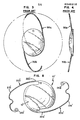
- FIGS. 1, 2 and 5-7 an intraocular lens designated generally as 10 incorporating the present invention is shown in FIGS. 1, 2 and 5-7.
- the intraocular lens 10 includes a central optical region or lens body 12 which preferrably, although not necessarily, is of a plano-convex cross- section.
- the optical lens body 12 has an upper portion 12c with an anteriorly convex upper surface 12a and a base portion 12d with a posteriorly substantially planer bottom surface 12b.
- the base portion 12d is relatively thin compared to the upper portion 12c.
- the optical lens body 12 has an apex 16, and a peripheral zone 15 including the outer periphery or circumference 13 of the lens body 12.
- the peripheral zone 15 is exterior to the optical zone 15a of the lens.
- the lens body 12 has a height h' as shown in FIG. 2, of a distance between the apex 16 and the bottom surface 12b.
- the height h' can be characterized as the distance from the apex 16 to the bottom surface 12b measured along the optical axis 24 of lens body 12.
- Interconnected to the periphery 13 of the lens body 12 are two curved elongated haptic members 20a,b extending outwardly from the lens body 12 along an arc exterior to the periphery 13. While the haptic members 20a,b as shown in FIG. 1, extend from the periphery 13 it is to be understood that the haptic members could extend outwardly from points anywhere within the peripheral zone 15.
- the lens body 12 of the lens 10 is centered and retained within the eye by the flexible haptic members 20a,b.
- the haptic members 20a,b include root ends 22a,b connected to the periphery 13 of the lens body 12 and outer or free ends 24a,b which each terminate at a tip 26a,b.
- the cross sectional dimension or diameter of the tip 26a,b is slightly enlarged to minimize irritation to the eye.
- the curved haptics with rounded ends fit snugly but comfortably inside the eye but avoid single point pressure which can lead to undesired complications, such as zonule rupture or ciliary body pressure in posterior chamber implants.
- the haptic members 20a,b are spaced and located approximately across the diameter of the lens body 12. While the haptic members 20a,b may be connected to the lens body 12 at the periphery 13 thereof by a number of known methods, in the preferred embodiment shown, the haptic members 20a,b and the lens body 12 are formed as an integral one-piece structure by forging and machining process. However, it will be appreciated that the lens 10 may also be produced by other suitable methods such as injection molding and lathing.
- the arc traversed by the haptic members 20a,b is substantially circular and curved toward the periphery 13 of the lens body 12.
- arcuate shaped haptics of a wide variety of shapes and designs are known such as "J" shaped (U.S. Patent No. 4,468,820 to Uhler et al; U.S. Patent No. 4,435,855 to Pannu) and "C” shaped (U.S. Patent No. 4,477,931 to Kelman; U.S. Patent No. 4,494,254 to Lopez).
- the lens of the present invention could incorporate haptics with any of these known shapes and designs, including a single haptic member or a combination of a single flexible haptic member together with an inflexible haptic support element.
- the haptic members 20a,b are easily compressed and held in a deformed condition thereby facilitating insertion of the lens into the eye.
- the resilient haptic member members 20a,b spontaneously tend to return to a normal position when released after being forced into the deformed position. This provides an intraocular lens which when positioned in the eye is self-fixating and self-centering and displays less of a tendency to tilt after being implanted in the eye.
- the intraocular lens body 12 is made of a biologically tolerable and optically suitable material such as polymethylmethacrylate (PMMA).
- PMMA polymethylmethacrylate
- the haptic members 20a,b are made of a flexible, compressible, resilient plastic material such as PMMA or polypropylene.
- the entire lens 10 is made as an integral one-piece structure of PMMA.
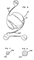
- FIGS. 3 and 4 A prior art lens, including haptic members 30a,b with the known uniform cross sectional dimension is shown in FIGS. 3 and 4.
- the lens 10 is provided with haptic members 20a,b having at least a portion thereof tapered (i.e. reduced in cross sectional dimension) in the direction along the length from the root ends 22a,b toward the free ends 24a,b.
- the preferred embodiment shown in FIGS. 1 and 2 includes fiber like haptic members 20a,b tapered along all dimensions of the length from the root ends 22a,b to the rounded tips 26a,b of the free ends 24a,b. More particularly, each of the haptic members 20a,b extends tangentially from the periphery 13 along a substantially circular arc exterior to the periphery 13. Each haptic 20a and.20b traverses an arc of about 140°. Each haptic member 20a and 20b has a circular cross section which is reduced along all dimensions of the haptic fiber, as best shown in FIGS. 5-7. While the preferred embodiment shown in FIGS. 1, 2 and 5-7 includes haptics having a circular cross section, other geometric shapes can be employed by one skilled in the art. By way of example only the cross sectional dimension for the tapered haptic can be rectangular, square or oval.
- FIGS. 1 and 2 shows haptic members tapered from the root ends 22a,b toward the free ends 24a,b over substantially the entire length of the haptics 20a,b the haptic members need only be tapered over a portion thereof in a direction along the length from the root ends 22a,b toward the free ends 24a,b in order to increase resistance to fracturing.
- the cross sectional dimension of a partially tapered haptic will be smaller at the free end than at the root end or base.
- FIG. 8 An alternate embodiment 10' is shown in FIG. 8 in which only a portion of the haptic members 20a',b' is tapered along the length from the root ends 22a',b l in the direction of the tips 26a',b'.
- the taper or area of reducing cross section of the haptic members 20a',b' extends only from root ends 22a',b' to outer points 21a',b' along the length of the haptic members. While extending the area of taper over a greater portion of the haptic increases flexibility, it is to be understood that in order to significantly strengthen the resistance of the haptic member to breakage, only the portion of the haptic substantially adjacent or proximate the root ends 22a,b need be tapered.
- substantially rectangular haptic members having one surface facing the periphery of the lens body and an opposite surface facing away from the periphery may be tapered by reducing. the distance between the periphery facing and periphery opposing surfaces over at least a portion of each haptic member along the length from the root end toward the free end.
- an intraocular lens with the tapered haptic of the present invention provides for a more even distribution of stress over the length of the haptic member than is exhibited by a haptic member having a uniform cross sectional dimension along its entire length as seen in FIGS. 3 and 4.
- An intraocular lens with a tapered haptic member also makes possible thinner more flexible haptics without compromising stength.
- a typical haptic such as seen. in FIGS. 3 and 4 has a diameter between 0.01 and 0.02 mm. over the entire length of the fiber.
- haptics 20a,b such as seen in FIG.
- the thinner tapered haptic not only exhibits greater flexibility but also possesses greater resistance to fracture. More flexible haptics in accordance with the present invention will ease handling of the lens prior to and during positioning in the eye and provide for more comfortable and better performing lens.
- Intraocular lenses 10 including the tapered haptics 20a,b of the present invention can be adopted for use as both posterior chamber intraocular lens implants as seen in FIG. 10 as well as anterior chamber intraocular lens implants as seen in'FIG. 11.
- the preferred embodiment of the lens 10 shown in FIG. 1 is of the type designed for posterior chamber implantation and includes an annular lip 17 projecting only rearwardly from the bottom surface 12b.
- the annular lip 17 sits against the posterior capsule 46 and creates a space between the capsule 46 and rear of the optical zone 15a of the lens body 12.
- the preferred embodiment shown in FIG. 1 also includes positioning holes 14.
- the posterior chamber type lens 10 will typically be utilized following extracapsular cataract extraction.
- the lens 10 is implanted in a human eye 40, in the posterior chamber 42 behind the iris 44.
- the cataract has been extracted from the capsular bag 46, leaving intact the posterior wall 46a and an annular flap portion 46b forming a cleft or fornix 46c.
- the capsular bag 46 is connected to the ciliary muscle in the eye wall 48 via suspensory ligaments 50. Vitreous humor in the region 52 behind the capsular bag 46 is prevented from flowing forward by the posterior wall 46a which assumes a generally planar shape.
- the haptic elements 20a,b support the lens 10 by engaging.the cleft or fornix portion 46c; thereby fixating the position of the lens 10 in the eye 40.
- the haptic members 20a",b” support the lens 10" in a spaced relationship anterior to the iris 44 of the eye 40.
- Specific design characteristics of a lens suitable for implanting in the anterior chamber such as proper curvature of the haptic members 20a",b” and the determination of the angle at which the haptics 20a",b” project from the lens body 12" are known by those skilled in the art.
- One embodiment of an anterior chamber lens is shown in FIG. 9, and parts thereof similar to lens 10 carry similar numbers with double prime (") marks added.
Abstract
Description
- This invention relates generally to intraocu- lar lenses to be used as artificial lens implants in eyes from which the cataractous natural lens has been removed, and more particularly to an improved structure for the haptic elements of an intraocular lens.
- The implantation of an intraocular lens for restoring vision after cataract surgery is well-known in the art. In general, two forms of surgery are used to remove cataracts. These are extracapsular cataract extraction and intracapsular extraction. (Discussed in U.S. Pat. Re. 31,626 to Hoffer) Following extraction of a cataractous lens, an intraocular lens is normally implanted in either the anterior or the posterior chamber of the eye. In an anterior chamber implant, the lens is generally situated forward of, or mounted to the iris. In the case of posterior chamber implants, the lens is situated behind the iris and may be mounted within the cleft or fornix of the capsule which remains in place after extracapsular surgery.
- In both anterior or posterior chamber implants, the lens is usually centered and fixed in position by one or more supporting strands or haptic members. While available intraocular lenses incorporate haptic member(s) having various geometric shapes and configurations, the typical haptic member is a flexible strand of non-biodegradable material which is fixed to the lens body, and exhibits specific spring-like memory qualities so that the haptic member can be compressed or off set from the normal rest position and thereafter returned to the fully extended condition when pressure is removed. (See U.S. Patent No. 4,468,820 to Uhler et al.; U.S. Patent No. 4,435,855 to Pannu; and U.S. Patent No. 4,494,254 to Lopez.)
- The typical diameter or thickness of a haptic member is about 0.1-0.2 mm; and therefore requires careful handling prior to and during implantation of the lens. For example, a haptic member can break or weaken when improperly handled with a surgical instrument, such as forceps. A broken haptic renders the lens useless. In the case of an integral one-piece lens a broken haptic requires that an entirely new lens be used.
- While not common, it is possible that improper handling of a haptic prior to lens implantation may damage the haptic without breaking it. If a lens with a damaged haptic is implanted and the haptic breaks subsequent to surgery, serious complications can arise. Dislocation of a lens subsequent to surgery could seriously impair vision and/or damage the eye.
- Among the wide variety of intraocular lenses having haptic support members, all known haptics have a uniform cross sectional dimension or thickness. When pressure is applied to the haptic (i.e. grasping root or base area of haptic with forceps) stress is concentrated at a relatively small area, thereby increasing the potential for breakage in the area of concentrated stress.
- It is well known that distortion of the eyeball can be caused by normal physical activities such as walking or rubbing the eyelids, as well as by more severe physical contact such as falls or collisions. When an intraocular lens has been implanted, distortion of the eyeball can place intermittent stress on the haptic members. This intermittent stress generally results in eye irritation, redness or other minor trauma. It is believed that these intermittent stresses can be minimized by increasing the flexibility of the haptic members. However, if haptics of the type currently available are made thinner to increase flexibility, the potential for breakage is also increased.
- Accordingly, a substantial need exists for a haptic support member which exhibits high resistance to breakage when handled. The present invention provides an artificial lens having an improved haptic member which is strengthened to minimize breakage. The strengthened haptic member of the present invention also provides for thinner more flexible haptics without sacrificing needed strength.
- The present invention is an intraocular lens for use as an artificial lens implant in an eye. The intraocular lens has an optical lens body and an improved means for positioning and supporting the lens body in the eye. Particularly, the lens body of the present invention is positioned and supported in the eye by at least one resilient haptic member having a root end and a free end. The haptic member is connected to the periphery of the lens body at the root end thereof. Preferably, the haptic member and lens body are integrally formed as a one-piece construction at the root end. The haptic member extends outwardly from the lens body along an arc exterior to the periphery of the lens body and is strengthened by having at least a portion thereof tapered in a direction along its length from the root end toward the tip. The tapered portion of the haptic member distributes externally applied stresses over a substantial length of the haptic member, thereby avoiding concentration of stress and minimizing the potential for breakage in the area of concentrated stress.
- In a preferred embodiment of the present invention, two curved elongated and resilient haptic members are integrally formed with the lens body at the periphery thereof. The two haptic members extend tangentially therefrom along an arc exterior to the periphery and have a cross sectional dimension which is reduced over at least a portion thereof in a direction along the length of the haptic from the root end toward the free end.
- In one embodiment of the present invention, the haptic members have a circular cross section which is reduced along all dimensions of the haptic in a direction along the entire length from the root end to the tip of the free end. In an alternate embodiment, the haptic members have a circular cross section which is reduced only over a portion of each haptic in the direction therealong from the root end toward the free end.
- In all preferred embodiments, the haptic members or members are tapered proximate the root end in the direction from the root end toward the free end. Inclusion of a tapered portion in at least the area of the root end increases the haptic's resistance to fracturing without compromising flexibility.
- The present invention makes possible thinner, more flexible haptics which can withstand greater deformation without fracturing. More flexible haptics such as provided for by the tapered haptics of the present invention can: adapt to distortion of the eye resulting from activities such as rubbing and pressing; deflect independently; adapt to the shape of the eye to equalize pressure; uniformly deflect in a plane perpendicular to the plane of the optic of the lens; control deflection forces over a broad area of the eye; and reduce tenderness in the eye. Accordingly, the advantages of increased flexibility made possible by the present invention provide for a safer, more comfortable and better performing intraocular lens.
- These and various other advantages and. features of the novelty which characterizes the invention are pointed out with particularity in the claims annexed hereto and forming a part hereof. However, for better understanding the invention, its advantages, and objects attained by its use, reference should be had to the drawings which form a further part hereof and to the accompanying descriptive matter in which there is illustrated and described a preferred embodiment of the invention.
-
- FIG. 1 is a top plan view of a preferred embodiment of the intraocular lens of the present invention;
- FIG. 2 is a side elevational view of the lens shown in FIG. 1.
- FIG. 3 is a top plan view of a prior art intraocular lens.
- FIG. 4 is a side elevational view of the prior art lens shown in FIG. 3.
- FIG. 5 is an elevational view taken along the line 5-5 in FIG. showing one embodiment of the taper of the haptic member of the present invention.
- FIG. 6 is a sectional view taken along line 6-6 in FIG. 5.
- FIG. 7 is a sectional view taken along line line 7-7 in FIG. 5.
- FIG. 8 is a top plan view of an alternate embodiment of the intraocular lens of the present invention.
- FIG. 9 is a top plan view of still another embodiment of the intraocular lens of the present invention.
- FIG. 10 is a simplified cross sectional schematic view of an eyeball with the lens of the present invention implanted in the posterior chamber.
- FIG. 11 is a simplified cross sectional schematic view of an eyeball implanted with the lens of the present invention implanted in the anterior chamber.
- Referring to the drawings, wherein like numerals represent like parts throughout the several views, an intraocular lens designated generally as 10 incorporating the present invention is shown in FIGS. 1, 2 and 5-7.
- The
intraocular lens 10 includes a central optical region orlens body 12 which preferrably, although not necessarily, is of a plano-convex cross- section. As shown in FIGS. 1 and 2, theoptical lens body 12 has an upper portion 12c with an anteriorly convexupper surface 12a and abase portion 12d with a posteriorly substantially planerbottom surface 12b. Thebase portion 12d is relatively thin compared to the upper portion 12c. Theoptical lens body 12 has an apex 16, and aperipheral zone 15 including the outer periphery orcircumference 13 of thelens body 12. Theperipheral zone 15 is exterior to theoptical zone 15a of the lens. Thelens body 12 has a height h' as shown in FIG. 2, of a distance between the apex 16 and thebottom surface 12b. The height h' can be characterized as the distance from the apex 16 to thebottom surface 12b measured along theoptical axis 24 oflens body 12. Interconnected to theperiphery 13 of thelens body 12 are two curved elongatedhaptic members 20a,b extending outwardly from thelens body 12 along an arc exterior to theperiphery 13. While thehaptic members 20a,b as shown in FIG. 1, extend from theperiphery 13 it is to be understood that the haptic members could extend outwardly from points anywhere within theperipheral zone 15. - The
lens body 12 of thelens 10 is centered and retained within the eye by the flexiblehaptic members 20a,b. As shown in FIG. 1, thehaptic members 20a,b include root ends 22a,b connected to theperiphery 13 of thelens body 12 and outer orfree ends 24a,b which each terminate at atip 26a,b. In the preferred embodiment shown in FIG. 1 the cross sectional dimension or diameter of thetip 26a,b is slightly enlarged to minimize irritation to the eye. Particularly, the curved haptics with rounded ends fit snugly but comfortably inside the eye but avoid single point pressure which can lead to undesired complications, such as zonule rupture or ciliary body pressure in posterior chamber implants. - In the preferred embodiment shown in FIG. 1, the
haptic members 20a,b are spaced and located approximately across the diameter of thelens body 12. While thehaptic members 20a,b may be connected to thelens body 12 at theperiphery 13 thereof by a number of known methods, in the preferred embodiment shown, thehaptic members 20a,b and thelens body 12 are formed as an integral one-piece structure by forging and machining process. However, it will be appreciated that thelens 10 may also be produced by other suitable methods such as injection molding and lathing. - In the preferred embodiment of FIGS. 1 and 2 the arc traversed by the
haptic members 20a,b is substantially circular and curved toward theperiphery 13 of thelens body 12. It is to be appreciated that arcuate shaped haptics of a wide variety of shapes and designs are known such as "J" shaped (U.S. Patent No. 4,468,820 to Uhler et al; U.S. Patent No. 4,435,855 to Pannu) and "C" shaped (U.S. Patent No. 4,477,931 to Kelman; U.S. Patent No. 4,494,254 to Lopez). The lens of the present invention could incorporate haptics with any of these known shapes and designs, including a single haptic member or a combination of a single flexible haptic member together with an inflexible haptic support element. - The
haptic members 20a,b are easily compressed and held in a deformed condition thereby facilitating insertion of the lens into the eye. Particularly, the resilienthaptic member members 20a,b spontaneously tend to return to a normal position when released after being forced into the deformed position. This provides an intraocular lens which when positioned in the eye is self-fixating and self-centering and displays less of a tendency to tilt after being implanted in the eye. - The
intraocular lens body 12 is made of a biologically tolerable and optically suitable material such as polymethylmethacrylate (PMMA). Thehaptic members 20a,b are made of a flexible, compressible, resilient plastic material such as PMMA or polypropylene. Preferably, theentire lens 10 is made as an integral one-piece structure of PMMA. - A prior art lens, including
haptic members 30a,b with the known uniform cross sectional dimension is shown in FIGS. 3 and 4. In contrast to the known structure for haptic members, according to the present invention thelens 10 is provided withhaptic members 20a,b having at least a portion thereof tapered (i.e. reduced in cross sectional dimension) in the direction along the length from the root ends 22a,b toward thefree ends 24a,b. - The preferred embodiment shown in FIGS. 1 and 2 includes fiber like
haptic members 20a,b tapered along all dimensions of the length from the root ends 22a,b to therounded tips 26a,b of thefree ends 24a,b. More particularly, each of thehaptic members 20a,b extends tangentially from theperiphery 13 along a substantially circular arc exterior to theperiphery 13. Each haptic 20a and.20b traverses an arc of about 140°. Eachhaptic member - It is to be understood that while the preferred embodiment in FIGS. 1 and 2 shows haptic members tapered from the root ends 22a,b toward the
free ends 24a,b over substantially the entire length of thehaptics 20a,b the haptic members need only be tapered over a portion thereof in a direction along the length from the root ends 22a,b toward thefree ends 24a,b in order to increase resistance to fracturing. The cross sectional dimension of a partially tapered haptic will be smaller at the free end than at the root end or base. - An alternate embodiment 10' is shown in FIG. 8 in which only a portion of the
haptic members 20a',b' is tapered along the length from the root ends 22a',bl in the direction of thetips 26a',b'. In FIG. 8, the taper or area of reducing cross section of thehaptic members 20a',b' extends only from root ends 22a',b' to outer points 21a',b' along the length of the haptic members. While extending the area of taper over a greater portion of the haptic increases flexibility, it is to be understood that in order to significantly strengthen the resistance of the haptic member to breakage, only the portion of the haptic substantially adjacent or proximate the root ends 22a,b need be tapered. - In another alternate embodiment not shown, substantially rectangular haptic members having one surface facing the periphery of the lens body and an opposite surface facing away from the periphery may be tapered by reducing. the distance between the periphery facing and periphery opposing surfaces over at least a portion of each haptic member along the length from the root end toward the free end.
- Providing an intraocular lens with the tapered haptic of the present invention provides for a more even distribution of stress over the length of the haptic member than is exhibited by a haptic member having a uniform cross sectional dimension along its entire length as seen in FIGS. 3 and 4. An intraocular lens with a tapered haptic member also makes possible thinner more flexible haptics without compromising stength. By way of example, a typical haptic such as seen. in FIGS. 3 and 4 has a diameter between 0.01 and 0.02 mm. over the entire length of the fiber. In contrast to this,
haptics 20a,b such as seen in FIG. 1 can be tapered from 0.15 to 0.08 mm in the direction from the root ends 22a,b toward thefree ends 24a,b. The thinner tapered haptic not only exhibits greater flexibility but also possesses greater resistance to fracture. More flexible haptics in accordance with the present invention will ease handling of the lens prior to and during positioning in the eye and provide for more comfortable and better performing lens. - The present invention is applicable to
intraocular lenses 10 of all geometric shapes and configurations.Intraocular lenses 10 including the taperedhaptics 20a,b of the present invention can be adopted for use as both posterior chamber intraocular lens implants as seen in FIG. 10 as well as anterior chamber intraocular lens implants as seen in'FIG. 11. - The preferred embodiment of the
lens 10 shown in FIG. 1 is of the type designed for posterior chamber implantation and includes anannular lip 17 projecting only rearwardly from thebottom surface 12b. When thelens 10 is implanted in theposterior chamber 42 as seen in FIG. 10 theannular lip 17 sits against theposterior capsule 46 and creates a space between thecapsule 46 and rear of theoptical zone 15a of thelens body 12. The preferred embodiment shown in FIG. 1 also includes positioning holes 14. - The posterior
chamber type lens 10 will typically be utilized following extracapsular cataract extraction. As illustrated in FIG. 10, thelens 10 is implanted in ahuman eye 40, in theposterior chamber 42 behind theiris 44. Preferably, the cataract has been extracted from thecapsular bag 46, leaving intact theposterior wall 46a and anannular flap portion 46b forming a cleft or fornix 46c. Thecapsular bag 46 is connected to the ciliary muscle in theeye wall 48 viasuspensory ligaments 50. Vitreous humor in the region 52 behind thecapsular bag 46 is prevented from flowing forward by theposterior wall 46a which assumes a generally planar shape. - When the
lens 10 is implanted in the posterior chamber of the eye, as seen in FIG. 10 thehaptic elements 20a,b support thelens 10 by engaging.the cleft or fornix portion 46c; thereby fixating the position of thelens 10 in theeye 40. - When the
lens 10 is adapted to be implanted in the anterior chamber of theeye 40 as seen in FIG. 11, thehaptic members 20a",b" support thelens 10" in a spaced relationship anterior to theiris 44 of theeye 40. Specific design characteristics of a lens suitable for implanting in the anterior chamber, such as proper curvature of thehaptic members 20a",b" and the determination of the angle at which thehaptics 20a",b" project from thelens body 12" are known by those skilled in the art. One embodiment of an anterior chamber lens is shown in FIG. 9, and parts thereof similar tolens 10 carry similar numbers with double prime (") marks added. - While the above embodiments have been described with reference to a plano-convex lens, it is understood that the. improved haptic member is also applicable to bi-convex lenses. The bi-convex lens would have a convex upper surface and convex bottom surface. The tapered haptics of the present invention could also be utilized with plano-concave lenses. Other modifications of the invention will be apparent to those skilled in the art in light of the foregoing description. This description is intended to provide specific examples of individual embodiments which clearly disclose the present invention. Accordingly, the invention is not limited to these embodiments or to the use of elements having specific configurations and shapes as presented herein. All alternative modifications and variations of the present invention which follows in the spirit and broad scope of the appended claims are included.
Claims (21)
Priority Applications (1)
| Application Number | Priority Date | Filing Date | Title |
|---|---|---|---|
| AT87850161T ATE66127T1 (en) | 1986-05-14 | 1987-05-14 | INTRAOCULAR LENS WITH TAPERED RETAINERS. |
Applications Claiming Priority (2)
| Application Number | Priority Date | Filing Date | Title |
|---|---|---|---|
| US06/862,989 US4725277A (en) | 1986-05-14 | 1986-05-14 | Intraocular lens with tapered haptics |
| US862989 | 1992-04-06 |
Publications (3)
| Publication Number | Publication Date |
|---|---|
| EP0246216A2 true EP0246216A2 (en) | 1987-11-19 |
| EP0246216A3 EP0246216A3 (en) | 1988-01-27 |
| EP0246216B1 EP0246216B1 (en) | 1991-08-14 |
Family
ID=25339947
Family Applications (1)
| Application Number | Title | Priority Date | Filing Date |
|---|---|---|---|
| EP87850161A Expired - Lifetime EP0246216B1 (en) | 1986-05-14 | 1987-05-14 | Intraocular lens with tapered haptics |
Country Status (7)
| Country | Link |
|---|---|
| US (1) | US4725277A (en) |
| EP (1) | EP0246216B1 (en) |
| AT (1) | ATE66127T1 (en) |
| CA (1) | CA1319792C (en) |
| DE (1) | DE3772098D1 (en) |
| ES (1) | ES2025212B3 (en) |
| GR (1) | GR3003016T3 (en) |
Cited By (24)
| Publication number | Priority date | Publication date | Assignee | Title |
|---|---|---|---|---|
| WO1990007914A1 (en) * | 1989-01-13 | 1990-07-26 | Pharmacia Production B.V. | Intraocular lens |
| EP0413057A1 (en) * | 1989-08-18 | 1991-02-20 | Chiron Adatomed Pharmazeutische und Medizintechnische Gesellschaft mbH | Posterior chamber intraocular lens |
| EP0478929A1 (en) * | 1990-09-29 | 1992-04-08 | Ipp Intellectual Property Protection Ag | Device for positioning an intraocular lens |
| US5135540A (en) * | 1989-01-13 | 1992-08-04 | Kabi Pharmacia Ab | Intraocular lens |
| WO1992015260A1 (en) * | 1991-03-01 | 1992-09-17 | Arnott Eric J | Intraocular lens with tapered holding loops |
| FR2687304A1 (en) * | 1992-02-14 | 1993-08-20 | Dalloz Sa Christian | Intraocular implant |
| EP0667754A1 (en) * | 1993-07-09 | 1995-08-23 | Kabi Pharmacia Opthalmics, Inc. | Intraocular lens with improved cylindrical haptic |
| EP0760232A1 (en) * | 1995-08-31 | 1997-03-05 | Nidek Co., Ltd | Intraocular lens |
| WO1998010717A1 (en) | 1996-09-09 | 1998-03-19 | Potsdamer Augenklinik Im Albrecht-Von Graefe-Haus Gmbh | Artificial, deformable intraocular eye lens |
| WO2000019944A1 (en) * | 1998-10-05 | 2000-04-13 | Allergan Sales, Inc. | Posterior/anterior chamber intraocular lenses |
| WO2009141354A1 (en) * | 2008-05-21 | 2009-11-26 | Medicontur Orvostechnikai Korlátolt Felelösségü Társaság | Intraocular lens |
| US9011532B2 (en) | 2009-06-26 | 2015-04-21 | Abbott Medical Optics Inc. | Accommodating intraocular lenses |
| US9039760B2 (en) | 2006-12-29 | 2015-05-26 | Abbott Medical Optics Inc. | Pre-stressed haptic for accommodating intraocular lens |
| US9271830B2 (en) | 2002-12-05 | 2016-03-01 | Abbott Medical Optics Inc. | Accommodating intraocular lens and method of manufacture thereof |
| US9381081B2 (en) | 2012-03-12 | 2016-07-05 | Doci Innovations GmbH (Claus Simandi) | Intraocular lens having helical haptics of shape memory |
| US9421089B2 (en) | 2007-07-05 | 2016-08-23 | Visiogen, Inc. | Intraocular lens with post-implantation adjustment capabilities |
| US9504560B2 (en) | 2002-01-14 | 2016-11-29 | Abbott Medical Optics Inc. | Accommodating intraocular lens with outer support structure |
| US9603703B2 (en) | 2009-08-03 | 2017-03-28 | Abbott Medical Optics Inc. | Intraocular lens and methods for providing accommodative vision |
| US9636213B2 (en) | 2005-09-30 | 2017-05-02 | Abbott Medical Optics Inc. | Deformable intraocular lenses and lens systems |
| US9814570B2 (en) | 1999-04-30 | 2017-11-14 | Abbott Medical Optics Inc. | Ophthalmic lens combinations |
| US9968441B2 (en) | 2008-03-28 | 2018-05-15 | Johnson & Johnson Surgical Vision, Inc. | Intraocular lens having a haptic that includes a cap |
| US9987125B2 (en) | 2012-05-02 | 2018-06-05 | Johnson & Johnson Surgical Vision, Inc. | Intraocular lens with shape changing capability to provide enhanced accomodation and visual acuity |
| US10722400B2 (en) | 2011-09-12 | 2020-07-28 | Amo Development, Llc | Hybrid ophthalmic interface apparatus and method of interfacing a surgical laser with an eye |
| US11707354B2 (en) | 2017-09-11 | 2023-07-25 | Amo Groningen B.V. | Methods and apparatuses to increase intraocular lenses positional stability |
Families Citing this family (74)
| Publication number | Priority date | Publication date | Assignee | Title |
|---|---|---|---|---|
| US4919662A (en) * | 1988-09-16 | 1990-04-24 | Minnesota Mining And Manufacturing Company | Hydrogel implant lens construction reconfigured dehydrated re-hydrated in situ |
| CA2019201A1 (en) * | 1989-06-19 | 1990-12-19 | John D. Hunkeler | Single piece ovoid intraocular lens with haptic |
| US5049156A (en) * | 1989-10-30 | 1991-09-17 | Nitto Denko Corporation | Intra-ocular lens |
| DE4038088C2 (en) * | 1990-11-29 | 1994-05-19 | Klaas Dieter | Artificial eye lens implant |
| US5197981A (en) * | 1992-04-23 | 1993-03-30 | Alcon Surgical, Inc. | Intraocular lens having haptic of specific curvature and proportion |
| US5578082A (en) * | 1994-05-27 | 1996-11-26 | Allergan | IOL for optimal capsular bag fit |
| US5716403A (en) * | 1995-12-06 | 1998-02-10 | Alcon Laboratories, Inc. | Single piece foldable intraocular lens |
| US5928282A (en) * | 1997-06-13 | 1999-07-27 | Bausch & Lomb Surgical, Inc. | Intraocular lens |
| US6228115B1 (en) | 1998-11-05 | 2001-05-08 | Bausch & Lomb Surgical, Inc. | Intraocular lenses with improved axial stability |
| US6231603B1 (en) | 1998-11-10 | 2001-05-15 | Allergan Sales, Inc. | Accommodating multifocal intraocular lens |
| US6190410B1 (en) | 1999-04-29 | 2001-02-20 | Bausch & Lomb Surgical, Inc. | Intraocular lenses |
| US6200344B1 (en) | 1999-04-29 | 2001-03-13 | Bausch & Lomb Surgical, Inc. | Inraocular lenses |
| US6406494B1 (en) | 1999-04-30 | 2002-06-18 | Allergan Sales, Inc. | Moveable intraocular lens |
| US6790232B1 (en) | 1999-04-30 | 2004-09-14 | Advanced Medical Optics, Inc. | Multifocal phakic intraocular lens |
| US6616692B1 (en) | 1999-04-30 | 2003-09-09 | Advanced Medical Optics, Inc. | Intraocular lens combinations |
| US6461384B1 (en) | 1999-06-17 | 2002-10-08 | Bausch & Lomb Incorporated | Intraocular lenses |
| US6599317B1 (en) | 1999-09-17 | 2003-07-29 | Advanced Medical Optics, Inc. | Intraocular lens with a translational zone |
| US6645246B1 (en) | 1999-09-17 | 2003-11-11 | Advanced Medical Optics, Inc. | Intraocular lens with surrounded lens zone |
| US6475240B1 (en) | 2000-02-02 | 2002-11-05 | Advanced Medical Optics, Inc. | Anterior chamber intraocular lens and methods for reducing pupil ovalling |
| US6551354B1 (en) | 2000-03-09 | 2003-04-22 | Advanced Medical Optics, Inc. | Accommodating intraocular lens |
| US6398809B1 (en) | 2000-04-12 | 2002-06-04 | Bausch & Lomb Incorporated | Intraocular lens |
| US6547822B1 (en) | 2000-05-03 | 2003-04-15 | Advanced Medical Optics, Inc. | Opthalmic lens systems |
| US6616693B1 (en) | 2000-05-03 | 2003-09-09 | Advanced Medical Optics, Inc. | Flexible fixation members for angle-supported anterior chamber intraocular lenses |
| US6537317B1 (en) | 2000-05-03 | 2003-03-25 | Advanced Medical Optics, Inc. | Binocular lens systems |
| US6554859B1 (en) | 2000-05-03 | 2003-04-29 | Advanced Medical Optics, Inc. | Accommodating, reduced ADD power multifocal intraocular lenses |
| DE10026717A1 (en) * | 2000-05-30 | 2001-12-13 | Rodenstock Optik G | Photochromic plastic object with permanently increased contrast |
| US6660035B1 (en) | 2000-08-02 | 2003-12-09 | Advanced Medical Optics, Inc. | Accommodating intraocular lens with suspension structure |
| US20040151755A1 (en) * | 2000-12-21 | 2004-08-05 | Osman Rathore | Antimicrobial lenses displaying extended efficacy, processes to prepare them and methods of their use |
| US7780729B2 (en) | 2004-04-16 | 2010-08-24 | Visiogen, Inc. | Intraocular lens |
| AU2002240147A1 (en) * | 2001-02-01 | 2002-08-12 | Tekia, Inc. | Two part "l"- or "s"-shaped phakic iol |
| US6576012B2 (en) | 2001-03-28 | 2003-06-10 | Advanced Medical Optics, Inc. | Binocular lens systems |
| US6638305B2 (en) | 2001-05-15 | 2003-10-28 | Advanced Medical Optics, Inc. | Monofocal intraocular lens convertible to multifocal intraocular lens |
| US20030095230A1 (en) * | 2001-08-02 | 2003-05-22 | Neely Frank L. | Antimicrobial lenses and methods of their use related patent applications |
| US20080299179A1 (en) * | 2002-09-06 | 2008-12-04 | Osman Rathore | Solutions for ophthalmic lenses containing at least one silicone containing component |
| US20040150788A1 (en) * | 2002-11-22 | 2004-08-05 | Ann-Margret Andersson | Antimicrobial lenses, processes to prepare them and methods of their use |
| US20040068317A1 (en) * | 2002-10-07 | 2004-04-08 | Knight Patricia M. | Anterior chamber intraocular lens with size and position indicators |
| US20040082993A1 (en) | 2002-10-25 | 2004-04-29 | Randall Woods | Capsular intraocular lens implant having a refractive liquid therein |
| US7025781B2 (en) * | 2003-01-31 | 2006-04-11 | Delary Alberto Kahn | Artificial iris diaphragm implant |
| US7303582B2 (en) | 2003-03-21 | 2007-12-04 | Advanced Medical Optics, Inc. | Foldable angle-fixated intraocular lens |
| US7416737B2 (en) * | 2003-11-18 | 2008-08-26 | Johnson & Johnson Vision Care, Inc. | Antimicrobial lenses, processes to prepare them and methods of their use |
| US20050131535A1 (en) | 2003-12-15 | 2005-06-16 | Randall Woods | Intraocular lens implant having posterior bendable optic |
| US20050187621A1 (en) * | 2004-02-24 | 2005-08-25 | Brady Daniel G. | Foldable unitary intraocular lens |
| US9730787B2 (en) * | 2006-10-04 | 2017-08-15 | Hoya Corporation | Soft intraocular lens |
| US20080102095A1 (en) | 2006-10-31 | 2008-05-01 | Kent Young | Acidic processes to prepare antimicrobial contact lenses |
| US20080100797A1 (en) * | 2006-10-31 | 2008-05-01 | Nayiby Alvarez-Carrigan | Antimicrobial contact lenses with reduced haze and preparation thereof |
| US7968650B2 (en) | 2006-10-31 | 2011-06-28 | Johnson & Johnson Vision Care, Inc. | Polymeric compositions comprising at least one volume excluding polymer |
| BRPI0717881A2 (en) * | 2006-10-31 | 2014-03-25 | Johnson & Johnson Vision Care | PROCESS TO PREPARE ANTIMICROBIAN CONTACT LENS |
| WO2008083283A2 (en) | 2006-12-29 | 2008-07-10 | Advanced Medical Optics, Inc. | Multifocal accommodating intraocular lens |
| US7713299B2 (en) | 2006-12-29 | 2010-05-11 | Abbott Medical Optics Inc. | Haptic for accommodating intraocular lens |
| US7993398B2 (en) * | 2007-04-24 | 2011-08-09 | Abbott Medical Optics Inc. | Angle indicator for capsular bag size measurement |
| WO2009120910A1 (en) | 2007-04-24 | 2009-10-01 | Abbott Medical Optics Inc. | Systems for ocular measurements |
| US9216080B2 (en) | 2007-08-27 | 2015-12-22 | Amo Groningen B.V. | Toric lens with decreased sensitivity to cylinder power and rotation and method of using the same |
| US8974526B2 (en) | 2007-08-27 | 2015-03-10 | Amo Groningen B.V. | Multizonal lens with extended depth of focus |
| AU2009214036B2 (en) | 2008-02-15 | 2014-04-17 | Amo Regional Holdings | System, ophthalmic lens, and method for extending depth of focus |
| US8439498B2 (en) | 2008-02-21 | 2013-05-14 | Abbott Medical Optics Inc. | Toric intraocular lens with modified power characteristics |
| US8862447B2 (en) | 2010-04-30 | 2014-10-14 | Amo Groningen B.V. | Apparatus, system and method for predictive modeling to design, evaluate and optimize ophthalmic lenses |
| EP2399548B1 (en) | 2009-02-20 | 2017-12-20 | Hoya Corporation | Soft intraocular lens and method of manufacturing same |
| WO2011075651A1 (en) | 2009-12-18 | 2011-06-23 | Abbott Medical Optics Inc. | Limited echelette lens, systems and methods |
| US9690115B2 (en) | 2010-04-13 | 2017-06-27 | Johnson & Johnson Vision Care, Inc. | Contact lenses displaying reduced indoor glare |
| US8697770B2 (en) | 2010-04-13 | 2014-04-15 | Johnson & Johnson Vision Care, Inc. | Pupil-only photochromic contact lenses displaying desirable optics and comfort |
| US8877103B2 (en) | 2010-04-13 | 2014-11-04 | Johnson & Johnson Vision Care, Inc. | Process for manufacture of a thermochromic contact lens material |
| US9817246B2 (en) | 2010-12-01 | 2017-11-14 | Amo Groningen B.V. | Multifocal lens having an optical add power progression, and a system and method of providing same |
| US20130083286A1 (en) | 2011-09-30 | 2013-04-04 | Johnson & Johnson Vision Care, Inc. | Method of creating a visible mark on lens using a leuco dye |
| US20130083287A1 (en) | 2011-09-30 | 2013-04-04 | Johnson & Johnson Vision Care, Inc. | Method of creating a visible mark on lens using a leuco dye |
| AU2013353764B2 (en) | 2012-12-04 | 2018-12-06 | Amo Groningen B.V. | Lenses systems and methods for providing binocular customized treatments to correct presbyopia |
| US20140371851A1 (en) * | 2013-06-16 | 2014-12-18 | Eli Aharoni | Haptics for intraocular devices |
| CA3013857A1 (en) | 2016-02-09 | 2017-08-17 | Amo Groningen B.V. | Progressive power intraocular lens, and methods of use and manufacture |
| US11123178B2 (en) | 2016-03-23 | 2021-09-21 | Johnson & Johnson Surgical Vision, Inc. | Power calculator for an ophthalmic apparatus with corrective meridians having extended tolerance or operation band |
| EP3432828B1 (en) | 2016-03-23 | 2021-09-22 | Johnson & Johnson Surgical Vision, Inc. | Ophthalmic apparatus with corrective meridians having extended tolerance band |
| AU2017352030B2 (en) | 2016-10-25 | 2023-03-23 | Amo Groningen B.V. | Realistic eye models to design and evaluate intraocular lenses for a large field of view |
| US10739227B2 (en) | 2017-03-23 | 2020-08-11 | Johnson & Johnson Surgical Vision, Inc. | Methods and systems for measuring image quality |
| EP3687447A1 (en) | 2017-11-30 | 2020-08-05 | AMO Groningen B.V. | Intraocular lenses that improve post-surgical spectacle independent and methods of manufacturing thereof |
| US11724471B2 (en) | 2019-03-28 | 2023-08-15 | Johnson & Johnson Vision Care, Inc. | Methods for the manufacture of photoabsorbing contact lenses and photoabsorbing contact lenses produced thereby |
| US11886046B2 (en) | 2019-12-30 | 2024-01-30 | Amo Groningen B.V. | Multi-region refractive lenses for vision treatment |
Citations (3)
| Publication number | Priority date | Publication date | Assignee | Title |
|---|---|---|---|---|
| US4435855A (en) * | 1980-04-01 | 1984-03-13 | Pannu Jaswant S | Universal intraocular lens and a method of measuring an eye chamber size |
| US4476591A (en) * | 1982-10-07 | 1984-10-16 | Arnott Eric J | Lens implants for insertion in the human eye |
| EP0128784A2 (en) * | 1983-05-16 | 1984-12-19 | Danièle Sylvie Aron-Rosa | Posterior chamber ocular implant |
Family Cites Families (9)
| Publication number | Priority date | Publication date | Assignee | Title |
|---|---|---|---|---|
| US31626A (en) * | 1861-03-05 | Enema-syringe | ||
| US4159546A (en) * | 1977-06-15 | 1979-07-03 | Shearing Steven P | Intraocular lens |
| US4174543A (en) * | 1978-06-01 | 1979-11-20 | Kelman Charles D | Intraocular lenses |
| US4370760A (en) * | 1981-03-25 | 1983-02-01 | Kelman Charles D | Anterior chamber intraocular lens |
| US4494254A (en) * | 1982-05-03 | 1985-01-22 | Osvaldo Lopez | Intraocular lens |
| US4468820A (en) * | 1982-05-10 | 1984-09-04 | Precision-Cosmet Co., Inc. | Haptic attachment for intraocular lenses |
| US4477931A (en) * | 1983-03-21 | 1984-10-23 | Kelman Charles D | Intraocular lens with flexible C-shaped supports |
| US4556998A (en) * | 1983-08-04 | 1985-12-10 | Siepser Steven B | Artificial intraocular lenses and method for their surgical implantation |
| AU582123B2 (en) * | 1983-08-30 | 1989-03-16 | Iolco Pty Ltd | Intraocular lens implants |
-
1986
- 1986-05-14 US US06/862,989 patent/US4725277A/en not_active Expired - Lifetime
-
1987
- 1987-05-05 CA CA000536383A patent/CA1319792C/en not_active Expired - Fee Related
- 1987-05-14 EP EP87850161A patent/EP0246216B1/en not_active Expired - Lifetime
- 1987-05-14 AT AT87850161T patent/ATE66127T1/en not_active IP Right Cessation
- 1987-05-14 DE DE8787850161T patent/DE3772098D1/en not_active Expired - Fee Related
- 1987-05-14 ES ES87850161T patent/ES2025212B3/en not_active Expired - Lifetime
-
1991
- 1991-10-24 GR GR91401624T patent/GR3003016T3/en unknown
Patent Citations (3)
| Publication number | Priority date | Publication date | Assignee | Title |
|---|---|---|---|---|
| US4435855A (en) * | 1980-04-01 | 1984-03-13 | Pannu Jaswant S | Universal intraocular lens and a method of measuring an eye chamber size |
| US4476591A (en) * | 1982-10-07 | 1984-10-16 | Arnott Eric J | Lens implants for insertion in the human eye |
| EP0128784A2 (en) * | 1983-05-16 | 1984-12-19 | Danièle Sylvie Aron-Rosa | Posterior chamber ocular implant |
Cited By (32)
| Publication number | Priority date | Publication date | Assignee | Title |
|---|---|---|---|---|
| WO1990007914A1 (en) * | 1989-01-13 | 1990-07-26 | Pharmacia Production B.V. | Intraocular lens |
| US5135540A (en) * | 1989-01-13 | 1992-08-04 | Kabi Pharmacia Ab | Intraocular lens |
| EP0413057A1 (en) * | 1989-08-18 | 1991-02-20 | Chiron Adatomed Pharmazeutische und Medizintechnische Gesellschaft mbH | Posterior chamber intraocular lens |
| DE3927360A1 (en) * | 1989-08-18 | 1991-02-21 | Adatomed Pharma & Med | INTRAOCULAR REAR CHAMBER LENS |
| US5015254A (en) * | 1989-08-18 | 1991-05-14 | Adatomed Pharmazeutische Und Medizintechnische Gesellschaft Mbh | Intraocular posterior chamber lens |
| EP0478929A1 (en) * | 1990-09-29 | 1992-04-08 | Ipp Intellectual Property Protection Ag | Device for positioning an intraocular lens |
| WO1992015260A1 (en) * | 1991-03-01 | 1992-09-17 | Arnott Eric J | Intraocular lens with tapered holding loops |
| FR2687304A1 (en) * | 1992-02-14 | 1993-08-20 | Dalloz Sa Christian | Intraocular implant |
| EP0667754A1 (en) * | 1993-07-09 | 1995-08-23 | Kabi Pharmacia Opthalmics, Inc. | Intraocular lens with improved cylindrical haptic |
| EP0667754A4 (en) * | 1993-07-09 | 1996-03-27 | Kabi Pharmacia Opthalmics Inc | Intraocular lens with improved cylindrical haptic. |
| EP0760232A1 (en) * | 1995-08-31 | 1997-03-05 | Nidek Co., Ltd | Intraocular lens |
| WO1998010717A1 (en) | 1996-09-09 | 1998-03-19 | Potsdamer Augenklinik Im Albrecht-Von Graefe-Haus Gmbh | Artificial, deformable intraocular eye lens |
| WO2000019944A1 (en) * | 1998-10-05 | 2000-04-13 | Allergan Sales, Inc. | Posterior/anterior chamber intraocular lenses |
| US6238433B1 (en) | 1998-10-05 | 2001-05-29 | Allergan Sales, Inc. | Posterior/anterior chamber intraocular lenses and methods of implantation |
| US9814570B2 (en) | 1999-04-30 | 2017-11-14 | Abbott Medical Optics Inc. | Ophthalmic lens combinations |
| US9504560B2 (en) | 2002-01-14 | 2016-11-29 | Abbott Medical Optics Inc. | Accommodating intraocular lens with outer support structure |
| US10206773B2 (en) | 2002-12-05 | 2019-02-19 | Johnson & Johnson Surgical Vision, Inc. | Accommodating intraocular lens and method of manufacture thereof |
| US9271830B2 (en) | 2002-12-05 | 2016-03-01 | Abbott Medical Optics Inc. | Accommodating intraocular lens and method of manufacture thereof |
| US9636213B2 (en) | 2005-09-30 | 2017-05-02 | Abbott Medical Optics Inc. | Deformable intraocular lenses and lens systems |
| US9039760B2 (en) | 2006-12-29 | 2015-05-26 | Abbott Medical Optics Inc. | Pre-stressed haptic for accommodating intraocular lens |
| US9421089B2 (en) | 2007-07-05 | 2016-08-23 | Visiogen, Inc. | Intraocular lens with post-implantation adjustment capabilities |
| US9968441B2 (en) | 2008-03-28 | 2018-05-15 | Johnson & Johnson Surgical Vision, Inc. | Intraocular lens having a haptic that includes a cap |
| WO2009141354A1 (en) * | 2008-05-21 | 2009-11-26 | Medicontur Orvostechnikai Korlátolt Felelösségü Társaság | Intraocular lens |
| FR2931356A1 (en) * | 2008-05-21 | 2009-11-27 | Medicontur Orvostechnikai Korl | INTRAOCULAR LENS |
| US10052194B2 (en) | 2009-06-26 | 2018-08-21 | Johnson & Johnson Surgical Vision, Inc. | Accommodating intraocular lenses |
| US9011532B2 (en) | 2009-06-26 | 2015-04-21 | Abbott Medical Optics Inc. | Accommodating intraocular lenses |
| US9603703B2 (en) | 2009-08-03 | 2017-03-28 | Abbott Medical Optics Inc. | Intraocular lens and methods for providing accommodative vision |
| US10105215B2 (en) | 2009-08-03 | 2018-10-23 | Johnson & Johnson Surgical Vision, Inc. | Intraocular lens and methods for providing accommodative vision |
| US10722400B2 (en) | 2011-09-12 | 2020-07-28 | Amo Development, Llc | Hybrid ophthalmic interface apparatus and method of interfacing a surgical laser with an eye |
| US9381081B2 (en) | 2012-03-12 | 2016-07-05 | Doci Innovations GmbH (Claus Simandi) | Intraocular lens having helical haptics of shape memory |
| US9987125B2 (en) | 2012-05-02 | 2018-06-05 | Johnson & Johnson Surgical Vision, Inc. | Intraocular lens with shape changing capability to provide enhanced accomodation and visual acuity |
| US11707354B2 (en) | 2017-09-11 | 2023-07-25 | Amo Groningen B.V. | Methods and apparatuses to increase intraocular lenses positional stability |
Also Published As
| Publication number | Publication date |
|---|---|
| EP0246216B1 (en) | 1991-08-14 |
| CA1319792C (en) | 1993-07-06 |
| US4725277A (en) | 1988-02-16 |
| GR3003016T3 (en) | 1993-02-17 |
| ATE66127T1 (en) | 1991-08-15 |
| EP0246216A3 (en) | 1988-01-27 |
| DE3772098D1 (en) | 1991-09-19 |
| ES2025212B3 (en) | 1992-03-16 |
Similar Documents
| Publication | Publication Date | Title |
|---|---|---|
| EP0246216B1 (en) | Intraocular lens with tapered haptics | |
| US4955902A (en) | Decentered intraocular lens | |
| US5776191A (en) | Fixation system for intraocular lens structures | |
| CA1237556A (en) | Fixation system for intraocularlens structures | |
| US4718904A (en) | Intraocular lens for capsular bag implantation | |
| US4316293A (en) | Flexible intraocular lens | |
| US4880427A (en) | Flexible posterior chamber lens | |
| US8197541B2 (en) | Accommodative lens implant, controlled by the ciliary muscle | |
| US6129760A (en) | Artificial lens | |
| US4576607A (en) | Intraocular lenses | |
| US7632431B2 (en) | Composite intraocular lens and method of manufacture thereof | |
| US20040148023A1 (en) | High gain wide range accommodating intraocular lens for implant into the capsular bag | |
| US4878911A (en) | Flexible one-piece posterior chamber lens | |
| EP1477138A1 (en) | Accommodating intraocular lens having T-shaped haptics | |
| US4662882A (en) | Intraocular lens | |
| GB2111835A (en) | Intraocular lens | |
| US20070129799A1 (en) | Accommodative lens implant, controlled by the ciliary muscle | |
| US6409763B1 (en) | Iris-supported intraocular lenses optics and rigid fixation members | |
| US4804361A (en) | Flexible one-piece posterior chamber lens | |
| US4871363A (en) | Corrective intraocular lens | |
| US4585455A (en) | Intraocular lens with iris spacer mechanism | |
| EP0289449A1 (en) | Posterior chamber lens | |
| US4502163A (en) | Haptic for intraocular lens | |
| US4950288A (en) | Corrective intraocular lens | |
| US20030208267A1 (en) | Anterior chamber phakic lens and methods of implantation |
Legal Events
| Date | Code | Title | Description |
|---|---|---|---|
| PUAI | Public reference made under article 153(3) epc to a published international application that has entered the european phase |
Free format text: ORIGINAL CODE: 0009012 |
|
| AK | Designated contracting states |
Kind code of ref document: A2 Designated state(s): AT BE CH DE ES FR GB GR IT LI LU NL SE |
|
| PUAL | Search report despatched |
Free format text: ORIGINAL CODE: 0009013 |
|
| AK | Designated contracting states |
Kind code of ref document: A3 Designated state(s): AT BE CH DE ES FR GB GR IT LI LU NL SE |
|
| 17P | Request for examination filed |
Effective date: 19880727 |
|
| 17Q | First examination report despatched |
Effective date: 19900206 |
|
| GRAA | (expected) grant |
Free format text: ORIGINAL CODE: 0009210 |
|
| AK | Designated contracting states |
Kind code of ref document: B1 Designated state(s): AT BE CH DE ES FR GB GR IT LI LU NL SE |
|
| REF | Corresponds to: |
Ref document number: 66127 Country of ref document: AT Date of ref document: 19910815 Kind code of ref document: T |
|
| REF | Corresponds to: |
Ref document number: 3772098 Country of ref document: DE Date of ref document: 19910919 |
|
| ITF | It: translation for a ep patent filed |
Owner name: ING. A. GIAMBROCONO & C. S.R.L. |
|
| ET | Fr: translation filed | ||
| REG | Reference to a national code |
Ref country code: ES Ref legal event code: FG2A Ref document number: 2025212 Country of ref document: ES Kind code of ref document: B3 |
|
| PGFP | Annual fee paid to national office [announced via postgrant information from national office to epo] |
Ref country code: FR Payment date: 19920511 Year of fee payment: 6 |
|
| PGFP | Annual fee paid to national office [announced via postgrant information from national office to epo] |
Ref country code: SE Payment date: 19920521 Year of fee payment: 6 |
|
| PGFP | Annual fee paid to national office [announced via postgrant information from national office to epo] |
Ref country code: NL Payment date: 19920531 Year of fee payment: 6 |
|
| PGFP | Annual fee paid to national office [announced via postgrant information from national office to epo] |
Ref country code: BE Payment date: 19920604 Year of fee payment: 6 |
|
| PLBE | No opposition filed within time limit |
Free format text: ORIGINAL CODE: 0009261 |
|
| STAA | Information on the status of an ep patent application or granted ep patent |
Free format text: STATUS: NO OPPOSITION FILED WITHIN TIME LIMIT |
|
| 26N | No opposition filed | ||
| PGFP | Annual fee paid to national office [announced via postgrant information from national office to epo] |
Ref country code: LU Payment date: 19920811 Year of fee payment: 6 |
|
| REG | Reference to a national code |
Ref country code: GR Ref legal event code: FG4A Free format text: 3003016 |
|
| EPTA | Lu: last paid annual fee | ||
| PG25 | Lapsed in a contracting state [announced via postgrant information from national office to epo] |
Ref country code: LU Free format text: LAPSE BECAUSE OF NON-PAYMENT OF DUE FEES Effective date: 19930514 |
|
| PG25 | Lapsed in a contracting state [announced via postgrant information from national office to epo] |
Ref country code: SE Effective date: 19930515 |
|
| PG25 | Lapsed in a contracting state [announced via postgrant information from national office to epo] |
Ref country code: BE Effective date: 19930531 |
|
| BERE | Be: lapsed |
Owner name: PRECISION-COSMET CO. INC. Effective date: 19930531 |
|
| PG25 | Lapsed in a contracting state [announced via postgrant information from national office to epo] |
Ref country code: NL Effective date: 19931201 |
|
| NLV4 | Nl: lapsed or anulled due to non-payment of the annual fee | ||
| PG25 | Lapsed in a contracting state [announced via postgrant information from national office to epo] |
Ref country code: FR Effective date: 19940131 |
|
| REG | Reference to a national code |
Ref country code: FR Ref legal event code: ST |
|
| EUG | Se: european patent has lapsed |
Ref document number: 87850161.8 Effective date: 19931210 |
|
| PGFP | Annual fee paid to national office [announced via postgrant information from national office to epo] |
Ref country code: GR Payment date: 19960429 Year of fee payment: 10 |
|
| PGFP | Annual fee paid to national office [announced via postgrant information from national office to epo] |
Ref country code: AT Payment date: 19970423 Year of fee payment: 11 |
|
| PG25 | Lapsed in a contracting state [announced via postgrant information from national office to epo] |
Ref country code: GR Free format text: THE PATENT HAS BEEN ANNULLED BY A DECISION OF A NATIONAL AUTHORITY Effective date: 19971130 |
|
| REG | Reference to a national code |
Ref country code: GR Ref legal event code: MM2A Free format text: 3003016 |
|
| PG25 | Lapsed in a contracting state [announced via postgrant information from national office to epo] |
Ref country code: AT Free format text: LAPSE BECAUSE OF NON-PAYMENT OF DUE FEES Effective date: 19980514 |
|
| PGFP | Annual fee paid to national office [announced via postgrant information from national office to epo] |
Ref country code: GB Payment date: 20010404 Year of fee payment: 15 |
|
| PGFP | Annual fee paid to national office [announced via postgrant information from national office to epo] |
Ref country code: ES Payment date: 20010516 Year of fee payment: 15 |
|
| PGFP | Annual fee paid to national office [announced via postgrant information from national office to epo] |
Ref country code: DE Payment date: 20010530 Year of fee payment: 15 |
|
| PGFP | Annual fee paid to national office [announced via postgrant information from national office to epo] |
Ref country code: CH Payment date: 20010627 Year of fee payment: 15 |
|
| REG | Reference to a national code |
Ref country code: GB Ref legal event code: IF02 |
|
| PG25 | Lapsed in a contracting state [announced via postgrant information from national office to epo] |
Ref country code: GB Free format text: LAPSE BECAUSE OF NON-PAYMENT OF DUE FEES Effective date: 20020514 |
|
| PG25 | Lapsed in a contracting state [announced via postgrant information from national office to epo] |
Ref country code: ES Free format text: LAPSE BECAUSE OF NON-PAYMENT OF DUE FEES Effective date: 20020516 |
|
| PG25 | Lapsed in a contracting state [announced via postgrant information from national office to epo] |
Ref country code: LI Free format text: LAPSE BECAUSE OF NON-PAYMENT OF DUE FEES Effective date: 20020531 Ref country code: CH Free format text: LAPSE BECAUSE OF NON-PAYMENT OF DUE FEES Effective date: 20020531 |
|
| PG25 | Lapsed in a contracting state [announced via postgrant information from national office to epo] |
Ref country code: DE Free format text: LAPSE BECAUSE OF NON-PAYMENT OF DUE FEES Effective date: 20021203 |
|
| GBPC | Gb: european patent ceased through non-payment of renewal fee |
Effective date: 20020514 |
|
| REG | Reference to a national code |
Ref country code: CH Ref legal event code: PL |
|
| REG | Reference to a national code |
Ref country code: ES Ref legal event code: FD2A Effective date: 20030611 |
|
| PG25 | Lapsed in a contracting state [announced via postgrant information from national office to epo] |
Ref country code: IT Free format text: LAPSE BECAUSE OF NON-PAYMENT OF DUE FEES;WARNING: LAPSES OF ITALIAN PATENTS WITH EFFECTIVE DATE BEFORE 2007 MAY HAVE OCCURRED AT ANY TIME BEFORE 2007. THE CORRECT EFFECTIVE DATE MAY BE DIFFERENT FROM THE ONE RECORDED. Effective date: 20050514 |