EP0086640A2 - Non-metallic, bio-compatible hemostatic clips - Google Patents
Non-metallic, bio-compatible hemostatic clips Download PDFInfo
- Publication number
- EP0086640A2 EP0086640A2 EP83300698A EP83300698A EP0086640A2 EP 0086640 A2 EP0086640 A2 EP 0086640A2 EP 83300698 A EP83300698 A EP 83300698A EP 83300698 A EP83300698 A EP 83300698A EP 0086640 A2 EP0086640 A2 EP 0086640A2
- Authority
- EP
- European Patent Office
- Prior art keywords
- clip
- leg member
- leg
- vessel clamping
- vessel
- Prior art date
- Legal status (The legal status is an assumption and is not a legal conclusion. Google has not performed a legal analysis and makes no representation as to the accuracy of the status listed.)
- Granted
Links
Images


Classifications
-
- A—HUMAN NECESSITIES
- A61—MEDICAL OR VETERINARY SCIENCE; HYGIENE
- A61B—DIAGNOSIS; SURGERY; IDENTIFICATION
- A61B17/00—Surgical instruments, devices or methods, e.g. tourniquets
- A61B17/12—Surgical instruments, devices or methods, e.g. tourniquets for ligaturing or otherwise compressing tubular parts of the body, e.g. blood vessels, umbilical cord
- A61B17/122—Clamps or clips, e.g. for the umbilical cord
-
- A—HUMAN NECESSITIES
- A61—MEDICAL OR VETERINARY SCIENCE; HYGIENE
- A61L—METHODS OR APPARATUS FOR STERILISING MATERIALS OR OBJECTS IN GENERAL; DISINFECTION, STERILISATION OR DEODORISATION OF AIR; CHEMICAL ASPECTS OF BANDAGES, DRESSINGS, ABSORBENT PADS OR SURGICAL ARTICLES; MATERIALS FOR BANDAGES, DRESSINGS, ABSORBENT PADS OR SURGICAL ARTICLES
- A61L31/00—Materials for other surgical articles, e.g. stents, stent-grafts, shunts, surgical drapes, guide wires, materials for adhesion prevention, occluding devices, surgical gloves, tissue fixation devices
- A61L31/04—Macromolecular materials
Definitions
- the present invention relates to hemostatic clips and more particularly to hemostatic clips fabricated from bio-compatible polymeric materials which may be absorbable or non-absorbable in body tissue.
- the vessels may be severed downstream of the ligated portion.
- the vessel may be ligated at two spaced apart areas and the portion of the vessel between the ligation removed.
- a primary-reason for ligating vessels is to maintain the surgical site free from an excess of blood and to reduce blood loss in the patient.
- the tumor or organ may have to be separated from certain vessels. Before separating the vessels are ligated. Once a blood vessel is completely shut off, hemostasis, that is, the natural closing of the ligated end of the vessel so as to stop blood flow, will occur in several days depending on the vessel.
- the body in the meantime, will continue to allow blood flow around the ligated area through appropriate capillaries and secondary vessels with the natural physiological function of the body enlarging these by-pass vessels until adequate blood flow is obtained.
- there should be positive stopping of the blood flow in the main vessel that is, no leakage which might cause blood loss in the patient and may also disrupt the natural hemostasis and concurrent manufacture of new paths of blood flow in the patient.
- hemostatic clips made from bio-compatible polymeric materials which are absorbable or non-absorbable in body tissue.
- These clips comprise a pair of leg members connected at their proximal ends by a resilient hinge section and terminating at their distal ends in a locking latch means.
- the distal end of one of the leg members comprises a deflectable hook section.
- the distal end of the other leg member is configured to be engaged by the hook section when the leg members are pivoted about the hinge to close the clip about a blood vessel.
- the clips may fail.
- the failure usually occurs at the latch or hook section.
- sufficient pressure is placed between the vessel clamping surfaces of the legs of the clip that the hook section will deflect allowing the opposite leg to spring out from underneath the hook member and the clip open.
- the hemostatic clips of the present invention have good in vivo strength properties and have vessel clamping surfaces with minimal or no gap or in certain instances a controlled gap between the surfaces when the clip is in the closed position to provide positive clamping of vessels and, hence, obtain the desired hemostasis within the period of time of from about 3 to 5 days.
- the latching means becomes secure or more secure the greater the pressure placed on the vessel clamping surfaces which ensures that the clip remains in the closed and locked position in use.
- the hemostatic clips of the present invention comprise first and second leg members joined at their proximal ends by resilient hinge means and terminating at their distal ends in latching means.
- the hinge section according to the present invention is resilient; i.e., it has elastic memory and acts as a spring which assists in the packaging of the clip as well as the handling and placement of the clip.
- Each leg member has an outer surface and a vessel clamping inner face.
- the vessel clamping inner face is in opposition to a vessel clamping inner face of the other leg member.
- One leg member terminates at its distal end in a portion of the latch means. This portion comprises a deflectable hook member extending from the inner face of the leg member.
- the hook member has an inner face spaced from the inner face of the leg members and in certain embodiments substantially parallel thereto. In a preferred embodiment of the present invention, the end face of the hook member is beveled so as to form an acute angle with the inner face of the hook member.
- the other leg member terminates at its distal end in a complementary locking portion of the latch.
- This portion comprises an end face which fits underneath the hook member of the other leg.
- the end face of the other leg member has a bevel complementary to the bevel on the end face of the hook member.
- the complementary bevel forms an obtuse angle with the inner face of the second leg member and is adapted to deflect the hook member as the clip is closed.
- the clip is closed by pivoting the leg members about the binge means.
- the distal end of one leg member deflects and engages the hook member of the other leg member to lock the clip in the closed position.
- the leg members of our new clip are configured so when the clip is in the closed position the bending of the leg member carrying the hook member is greater than the bending of the opposite leg member. In use, this difference in bending causes the hook member to be urged towards the hinge means and secures the clip in the closed position.
- the greater the pressure placed on the vessel clamping surface of the leg member carrying the hook member the more the hook member is urged towards the resilient hinge means and the tighter and more secure the clip becomes.
- the vessel clamping surface of the leg member carrying the hook member has a concave radius of curvature extending from the hinge means to the hook member while the vessel clamping surface of the other leg member has a convex radius of curvature extending from the hinge means to the distal end of the member.
- the radius of the curvature of the vessel clamping surface of the latter leg member is smaller than the radius of curvature of the vessel clamping surface of the leg member carrying the hook member.
- the vessel clamping surface of the leg member carrying the hook member may be straight while the vessel clamping surface of the other leg member has a convex radius of curvature.
- the vessel clamping surface of the leg member carrying the hook member is concave while the vessel clamping surface of the opposite leg member is straight.
- a controlled gap is produced between the vessel clamping surfaces. This controlled gap embodiment is especially useful in the ligation of larger size blood vessels.
- the area moment of inertia of the leg member carrying the hook member is less than the area moment of inertia of the other leg member. This may be accomplished by reducing the cross-sectional area of the leg member carrying the hook member and increasing the cross-sectional area of the other leg member. By decreasing or varying the area moments of inertia, one can control the amount of force placed on the vessel clamping surface and, hence, bend the leg member carrying the hook member to a greater degree than the other leg member in accordance with the present invention.
- a preferred embodiment of the clip of the present invention is to have the vessel clamping surfaces of both leg members with a convex radius of curvature. This double convex configuration provides a squeezing force to the vessel equivalent to a clip having a greater moment of inertia thus allowing for a reduction of the bulk of the clip and the amount of material placed in the body.
- the outer surfaces of the leg members carry suitable means for allowing the clip to be picked up in the jaws of an appropriate forceps type hemostatic clip applier and closed about the vessel. In certain embodiments of the present invention this may be accomplished merely by providing the outer surface with an appropriate radius of curvature so that it will be held in the jaws of a forceps type clip applier.
- the outer surfaces include bosses extending transverse of the leg members which are adapted to fit into channels disposed in the jaws of a forceps type clip applier and are used to pick up the clip and close the clip about a blood vessel.
- the legs of the clips include interlocking means which prevent relative transverse movement between the vessel clamping surfaces when the clip is in the closed position.
- the hemostatic clip comprises two leg members 11 and 12.
- the leg members are connected at their proximal ends by the resilient hinge section 13.
- Leg member 11 terminates at its distal end in a hook member 14.
- the hook member has an inner face 15.
- the end surface of the hook member is beveled at 26 to assist in deflecting the hook member when the clip is closed.
- the vessel clamping surface 16 of the leg member 11 has a concave radius of curvature extending from the hinge to the start of the hook member.
- the other leg member 12 has vessel clamping surface 18 which has a convex radius of curvature extending from the hinge to the distal end of the leg member.
- the radius of curvature of the clamping surface 18 is smaller than the radius of curvature of clamping surface 16.
- Leg member 12 terminates in an end surface 19.
- this end surface is beveled and has a complementary bevel to the bevel on the hook member so as to assist in the deflection of the hook member when the clip is closed.
- the outer surfaces of the clip 20 and 22 are configured so as to be accepted by the jaws of a suitable forceps type applier and to allow those jaws to put pressure on the outer surfaces of the clip to close the clip.
- the clip is closed about a blood vessel as shown in Figure 2 by urging the distal ends of the two leg members together until the end surface 19 of the leg member 12 deflects the hook member 14 by engaging end surface 26 of the hook member on leg 11 as the two leg members are pivoted about the resilient hinge 13 and closed about the blood vessel 27.
- FIG 4 there is shown another embodiment of a hemostatic clip 30 of :he present invention.
- the hemostatic clip is constructed of two leg members 31 and 32 connected at their proximal ends by hinge section 33.
- the leg 31 terminates at its distal end in a hook member 34.
- the hook member has an inner face 35 substantially parallel to the vessel clamping surface 36 of the leg.
- the vessel clamping surface 36 of the leg is substantially straight.
- the leg member 32 terminates at its distal end in an end face 39.
- the vessel clamping surface 38 has a convex radius of curvature.
- each leg member Disposed on the outer surface of each leg member are cylindrical bosses 41 and 42.
- the bosses are used to manipulate the clip in a suitable instrument as will be described in conjunction with Figures 6 and 7.
- Figure 5 illustrates a forceps type ligating clip applier 60 comprising two handle members 61 and 62 crossing at a hinge point 63 and maintained in a normally open position by a spring 64.
- One handle extends beyond the hinge forming a jaw member 65 while the extension of the other handle also forms a corresponding jaw member 65.
- FIG. 6 illustrates the detailed construction of the jaws and the interaction of the jaws with the clip of Figure 4.
- the jaws are of identical design and are provided respectively with channels 66 and 67 extending rearwardly from the tips of the jaws.
- Each channel is provided with a cylindrical recess 68 and 69 disposed transverse of the channel and near the distal end thereof.
- the recesses are in alignment when the jaws of the applier are closed and are sized to receive the cylindrical lugs or bosses 41 and 42 of the clip.
- the channels forward of the recesses are deeper than to the rear of the recesses as illustrated in Figure 6. When the open clip is held in the applier, the cylindrical bosses on the clip extend into the cylindrical recesses in each jaw.
- the distal ends of the legs extend into the deeper or forward section of each jaw.
- the resilient or elastic memory of the hinge retains the clip in the recesses of the applier.
- the clip is initially loaded in the applier in a position as illustrated in Figure 6.
- the jaws 65 of the applier have been moved and the clip positioned over the vessel 37 to be ligated.
- the jaws of the applier are closed and the clip is locked over the vessel.
- the cylindrical lugs or bosses 41 and 42 of the legs rotate journal like in the cylindrical recesses 68 and 69 of the jaws.
- the jaws of the applier are opened to release the clip and vessel and a new clip is loaded in the applier. Since the jaws of the applier and the clip pick up features are identical, it is not necessary to orient the applier to the clip when loading the applier.
- the clip 70 comprises a pair of leg members 71 and 72 connected at their proximal ends by a resilient hinge section 73.
- the leg member 71 terminates at its distal end in a return engaging hook member 74.
- the vessel clamping surface 76 of this leg member has a concave radius of curvature extending from the resilient hinge to the start of the deflectable hook member.
- the opposite leg member 72 has its distal end terminating in a beveled portion 79 adapted to deflect the hook member of the other leg.
- the vessel clamping surface 78 of this leg member is straight. This configuration produces a gap between the vessel clamping surfaces when the clip is closed.
- the gap is controlled by the degree of concavity in the leg member carrying the hook.
- This embodiment is for use with the larger and more massive blood vessels.
- the outer surfaces of the leg members carry appropriate recesses 77 which will fit into corresponding bosses in the jaws of a clip applier.
- the clip 80 comprises a pair'of leg members 81 and 82 connected at their proximal ends by a resilient hinge section 83.
- the leg member 81 terminates at its distal end in a return hook member 84.
- the inner surface 85 of the hook member is substantially parallel to the vessel clamping surface 86 of the leg.
- the vessel clamping surface of the leg member 81 is straight.
- the corresponding leg member 82 terminates at its distal end in a beveled surface 89 adapted to deflect the hook member 84 when closing the clip.
- the vessel clamping surface 88 of this leg member is also straight and will be substantially parallel to the vessel clamping surface 86 when the clip is in a closed position.
- the outer surface 90 of the leg member 81 is curved to be accepted by the jaws of a suitable forceps type closing instrument while the outer surface of the other leg member 82 carries a boss 91 to be accepted by the opposite jaw of the forceps type clip applier.
- Figure 10 which is a cross-sectional view of the clip shown in Figure 9 closed and in place about a blood vessel 92, the cross-section of the leg member 81 carrying the hook member is substantially less than the cross-section of the other leg member 82.
- FIG 11 there is shown a preferred embodiment of a hemostatic clip of the present invention.
- the clip 100 comprises a pair of leg members 101 and 102 connected at their proximal ends by hinge section 103.
- the leg 101 terminates at its distal end in a hook member 104.
- the hook member has an inner face 105 substantially parallel to the vessel clamping surface 106 of the leg.
- the vessel clamping surface 106 has a slightly convex curved surface.
- the leg member 102 terminates at its distal end in end face 107.
- the vessel clamping surface 108 also has a slightly convex radius of curvature.
- At the end of the vessel clamping surface 108 there is an ear 109 and a recess 110.
- each leg member Upon closing of the clip (as previously described in conjunction with Figure 4) the ear 109 and recess 110 cooperate with a complimentary recess 111 and ear 112 disposed in vessel clamping surface 106.
- the engagement of the complimentary ears and recesses prevent lateral movement between the leg members when the clip is in the closed position.
- Disposed on the outer surface of each leg member are cylindrical bosses 113 and 114 which are used to manipulate and place the clip.
- the clips of the present invention may be constructed in various sizes according to their intended function. Hemostatic clips are usually less than 6 millimeters in length, about 1 1/2 millimeters in width and have a vessel clamping surface of about 3 millimeters in length. The dimensions of the clip may be reduced by about 50% for certain applications in microsurgery. Larger clips for special hemostatic applications and other functions such as closure of ova ducts or vasdeferens may have dimensions of about double those of a typical hemostatic clip.
- the various sizes of the clip are preferably matched with individual appliers having jaws tailored to the size of the clip for best performance.
- the clips of the present invention are most conveniently molded of biologically acceptable polymeric materials which may be absorbable or non-absorbable by body tissue.
- Preferred absorbable polymers include homopolymers and copolymers of glycolide and lactide and poly(p-dioxanone).
- Preferred non-absorbable polymers include nylon, polyester, and polypropylene. All these materials have been demonstrated to be biologically acceptable when used as sutures or other implantable medical devices.
- the clips of the present invention are preferably formed in an open position and may be easily and economically manufactured by injection molding or other suitable techniques.
Abstract
Description
- The present invention relates to hemostatic clips and more particularly to hemostatic clips fabricated from bio-compatible polymeric materials which may be absorbable or non-absorbable in body tissue.
- In many surgical procedures, it is often necessary to ligate a plurality of vessels within the surgical site.
- The vessels may be severed downstream of the ligated portion. In some instances, the vessel may be ligated at two spaced apart areas and the portion of the vessel between the ligation removed. A primary-reason for ligating vessels is to maintain the surgical site free from an excess of blood and to reduce blood loss in the patient. Also in certain surgical procedures wherein tumors or parts of organs and the like are to be removed, the tumor or organ may have to be separated from certain vessels. Before separating the vessels are ligated. Once a blood vessel is completely shut off, hemostasis, that is, the natural closing of the ligated end of the vessel so as to stop blood flow, will occur in several days depending on the vessel. The body, in the meantime, will continue to allow blood flow around the ligated area through appropriate capillaries and secondary vessels with the natural physiological function of the body enlarging these by-pass vessels until adequate blood flow is obtained. Hence, when ligating the vessel, there should be positive stopping of the blood flow in the main vessel; that is, no leakage which might cause blood loss in the patient and may also disrupt the natural hemostasis and concurrent manufacture of new paths of blood flow in the patient.
- In the past, this closing of the vessel was usually accomplished using ligatures; i.e., threads or filaments which the doctor tied around the vessel desired to be closed. This is a time consuming process and one wherein positive closure of the vessel is not always accomplished. In recent years, hemostatic clips have replaced ligatures in many surgical procedures to close blood vessels and other fluid ducts. Very often these hemostatic clips are narrow U or V shaped strips formed of tantalum or stainless steel which are capable of being deformed and possess sufficient strength to retain the deformation when clamped about a blood vessel.
- In co-pending commonly assigned patent application, Serial No. 276,131 filed June 22, 1981 and Serial No. 282,461 filed July 31, 1981 there are disclosed hemostatic clips made from bio-compatible polymeric materials which are absorbable or non-absorbable in body tissue. These clips comprise a pair of leg members connected at their proximal ends by a resilient hinge section and terminating at their distal ends in a locking latch means. The distal end of one of the leg members comprises a deflectable hook section. The distal end of the other leg member is configured to be engaged by the hook section when the leg members are pivoted about the hinge to close the clip about a blood vessel. These clips as described have been found satisfactory for ligating most blood vessels. However, in certain instances if the vessel is large and the pressure in the vessel great, the clips may fail. The failure usually occurs at the latch or hook section. In certain instances, sufficient pressure is placed between the vessel clamping surfaces of the legs of the clip that the hook section will deflect allowing the opposite leg to spring out from underneath the hook member and the clip open.
- We have discovered a new and improved hemostatic clip made from bio-compatible polymeric materials which comprise a pair of leg members connected at their proximal ends by a resilient hinge section and having a deflectable hook type latching means.
- The hemostatic clips of the present invention have good in vivo strength properties and have vessel clamping surfaces with minimal or no gap or in certain instances a controlled gap between the surfaces when the clip is in the closed position to provide positive clamping of vessels and, hence, obtain the desired hemostasis within the period of time of from about 3 to 5 days. The latching means becomes secure or more secure the greater the pressure placed on the vessel clamping surfaces which ensures that the clip remains in the closed and locked position in use.
- The hemostatic clips of the present invention comprise first and second leg members joined at their proximal ends by resilient hinge means and terminating at their distal ends in latching means. The hinge section according to the present invention is resilient; i.e., it has elastic memory and acts as a spring which assists in the packaging of the clip as well as the handling and placement of the clip.
- Each leg member has an outer surface and a vessel clamping inner face. The vessel clamping inner face is in opposition to a vessel clamping inner face of the other leg member. When the clip is in the closed position, there is a minimal or no gap or in certain instances a controlled gap between the vessel clamping faces. One leg member terminates at its distal end in a portion of the latch means. This portion comprises a deflectable hook member extending from the inner face of the leg member. The hook member has an inner face spaced from the inner face of the leg members and in certain embodiments substantially parallel thereto. In a preferred embodiment of the present invention, the end face of the hook member is beveled so as to form an acute angle with the inner face of the hook member. The other leg member terminates at its distal end in a complementary locking portion of the latch. This portion comprises an end face which fits underneath the hook member of the other leg. In a preferred embodiment, the end face of the other leg member has a bevel complementary to the bevel on the end face of the hook member. The complementary bevel forms an obtuse angle with the inner face of the second leg member and is adapted to deflect the hook member as the clip is closed.
- The clip is closed by pivoting the leg members about the binge means. The distal end of one leg member deflects and engages the hook member of the other leg member to lock the clip in the closed position. The leg members of our new clip are configured so when the clip is in the closed position the bending of the leg member carrying the hook member is greater than the bending of the opposite leg member. In use, this difference in bending causes the hook member to be urged towards the hinge means and secures the clip in the closed position. The greater the pressure placed on the vessel clamping surface of the leg member carrying the hook member, the more the hook member is urged towards the resilient hinge means and the tighter and more secure the clip becomes. In certain embodiments of the present invention, the vessel clamping surface of the leg member carrying the hook member has a concave radius of curvature extending from the hinge means to the hook member while the vessel clamping surface of the other leg member has a convex radius of curvature extending from the hinge means to the distal end of the member. The radius of the curvature of the vessel clamping surface of the latter leg member is smaller than the radius of curvature of the vessel clamping surface of the leg member carrying the hook member. In other embodiments of the present invention, the vessel clamping surface of the leg member carrying the hook member may be straight while the vessel clamping surface of the other leg member has a convex radius of curvature. In still other embodiments of the present invention, the vessel clamping surface of the leg member carrying the hook member is concave while the vessel clamping surface of the opposite leg member is straight. When using this latter embodiment a controlled gap is produced between the vessel clamping surfaces. This controlled gap embodiment is especially useful in the ligation of larger size blood vessels.
- In yet other embodiments of the present invention, the area moment of inertia of the leg member carrying the hook member is less than the area moment of inertia of the other leg member. This may be accomplished by reducing the cross-sectional area of the leg member carrying the hook member and increasing the cross-sectional area of the other leg member. By decreasing or varying the area moments of inertia, one can control the amount of force placed on the vessel clamping surface and, hence, bend the leg member carrying the hook member to a greater degree than the other leg member in accordance with the present invention. A preferred embodiment of the clip of the present invention is to have the vessel clamping surfaces of both leg members with a convex radius of curvature. This double convex configuration provides a squeezing force to the vessel equivalent to a clip having a greater moment of inertia thus allowing for a reduction of the bulk of the clip and the amount of material placed in the body.
- The outer surfaces of the leg members carry suitable means for allowing the clip to be picked up in the jaws of an appropriate forceps type hemostatic clip applier and closed about the vessel. In certain embodiments of the present invention this may be accomplished merely by providing the outer surface with an appropriate radius of curvature so that it will be held in the jaws of a forceps type clip applier. In preferred embodiments of the present invention, the outer surfaces include bosses extending transverse of the leg members which are adapted to fit into channels disposed in the jaws of a forceps type clip applier and are used to pick up the clip and close the clip about a blood vessel. In certain embodiments of the improved clip of the present invention, the legs of the clips include interlocking means which prevent relative transverse movement between the vessel clamping surfaces when the clip is in the closed position.
- The present invention will be described in greater detail in conjunction with the accompanying drawings wherein:
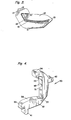
- Figure 1 is a greatly enlarged view in perspective of a hemostatic clip in accordance with the present invention;
- Figure 2 illustrates the clip of Figure 1 clamped about a blood vessel;
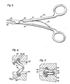
- Figure 3 is a cross-sectional view showing the clip of Figure 1 closed about a blood vessel;
- Figure 4 is a greatly enlarged view in perspective of another embodiment of a hemostatic clip according to the present invention;
- Figure 5 illustrates a forceps type applier useful with the clips of the present invention;
- Figure 6 illustrates the clip of Figure 4 retained in the jaws of a forceps type clip applier;
- Figure 7 illustrates the clip of Figure 4 closed and locked over a blood vessel in the jaws of the applier;
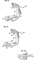
- Figure 8 is a greatly enlarged view in perspective of another embodiment of a hemostatic clip according to the present invention;
- Figure 9 is a greatly enlarged view in perspective of yet another embodiment of a hemostatic clip according to the present invention;
- Figure 10 is a cross-sectional view of the type of clip depicted in Figure 9; and
- Figure 11 is a greatly enlarged view in perspective of another embodiment of a clip according to the present invention.
- Referring to Figure 1, there is shown a
hemostatic clip 10 of the present invention. The hemostatic clip comprises twoleg members 11 and 12. The leg members are connected at their proximal ends by theresilient hinge section 13. Leg member 11 terminates at its distal end in ahook member 14. The hook member has aninner face 15. In a preferred embodiment, the end surface of the hook member is beveled at 26 to assist in deflecting the hook member when the clip is closed. Thevessel clamping surface 16 of the leg member 11 has a concave radius of curvature extending from the hinge to the start of the hook member. Theother leg member 12 hasvessel clamping surface 18 which has a convex radius of curvature extending from the hinge to the distal end of the leg member. The radius of curvature of the clampingsurface 18 is smaller than the radius of curvature of clampingsurface 16.Leg member 12 terminates in anend surface 19. Preferably this end surface is beveled and has a complementary bevel to the bevel on the hook member so as to assist in the deflection of the hook member when the clip is closed. The outer surfaces of theclip 20 and 22 are configured so as to be accepted by the jaws of a suitable forceps type applier and to allow those jaws to put pressure on the outer surfaces of the clip to close the clip. The clip is closed about a blood vessel as shown in Figure 2 by urging the distal ends of the two leg members together until theend surface 19 of theleg member 12 deflects thehook member 14 by engagingend surface 26 of the hook member on leg 11 as the two leg members are pivoted about theresilient hinge 13 and closed about theblood vessel 27. - As is more clearly shown in Figure 3, which is a cross-section of the closed clip, the radius of curvature of the vessel clamping
convex surface 18 of theleg member 12 is smaller than the radius of curvature of the concavevessel clamping surface 16 of the leg member 11 carrying thehook member 14. The bulkier the closed blood vessel the more force is developed between the vessel clamping surfaces, and the more the clampingsurface 16 of the leg member carrying the hook member is forced into a more concave position, thus drawing the hook member in the direction of the arrow towards theresilient hinge 13 and the more secure the clip becomes. - In Figure 4 there is shown another embodiment of a
hemostatic clip 30 of :he present invention. The hemostatic clip is constructed of twoleg members hinge section 33. Theleg 31 terminates at its distal end in ahook member 34. The hook member has aninner face 35 substantially parallel to thevessel clamping surface 36 of the leg. Thevessel clamping surface 36 of the leg is substantially straight. Theleg member 32 terminates at its distal end in anend face 39. Thevessel clamping surface 38 has a convex radius of curvature. Whenlegs hinge 33 to bring vessel clamping surfaces 38 and 35 together, thehook 34 is deflected by thesurface 39 of theleg 32 until the distal end ofleg 32 snaps underhook 34 and is thereby locked in place. The convex radius of curvature ofvessel clamping surface 38 places pressure on thesurface 36 when the clip is in the closed position. This pressure urges the hook member towards the resilient hinge portion to insure that the clip remains closed during use and more securely retains the vessel. - Disposed on the outer surface of each leg member are
cylindrical bosses - Figure 5 illustrates a forceps type
ligating clip applier 60 comprising two handlemembers hinge point 63 and maintained in a normally open position by aspring 64. One handle extends beyond the hinge forming ajaw member 65 while the extension of the other handle also forms acorresponding jaw member 65. - Figure 6 illustrates the detailed construction of the jaws and the interaction of the jaws with the clip of Figure 4. The jaws are of identical design and are provided respectively with
channels cylindrical recess 68 and 69 disposed transverse of the channel and near the distal end thereof. The recesses are in alignment when the jaws of the applier are closed and are sized to receive the cylindrical lugs orbosses jaws 65 of the applier have been moved and the clip positioned over thevessel 37 to be ligated. The jaws of the applier are closed and the clip is locked over the vessel. As the clip is closed, the cylindrical lugs orbosses cylindrical recesses 68 and 69 of the jaws. After the clip has been securely latched over the vessel to be ligated, the jaws of the applier are opened to release the clip and vessel and a new clip is loaded in the applier. Since the jaws of the applier and the clip pick up features are identical, it is not necessary to orient the applier to the clip when loading the applier. - Referring to Figure 8 there is shown another embodiment of a hemostatic clip of the present invention. In this embodiment, the
clip 70 comprises a pair ofleg members resilient hinge section 73. Theleg member 71 terminates at its distal end in a return engaginghook member 74. Thevessel clamping surface 76 of this leg member has a concave radius of curvature extending from the resilient hinge to the start of the deflectable hook member. Theopposite leg member 72 has its distal end terminating in abeveled portion 79 adapted to deflect the hook member of the other leg. Thevessel clamping surface 78 of this leg member is straight. This configuration produces a gap between the vessel clamping surfaces when the clip is closed. The gap is controlled by the degree of concavity in the leg member carrying the hook. This embodiment is for use with the larger and more massive blood vessels. In this embodiment, the outer surfaces of the leg members carryappropriate recesses 77 which will fit into corresponding bosses in the jaws of a clip applier. - In Figure 9 there is shown still another embodiment of a hemostatic clip of the present invention. In this embodiment, the
clip 80 comprises apair'of leg members leg member 81 terminates at its distal end in areturn hook member 84. Theinner surface 85 of the hook member is substantially parallel to thevessel clamping surface 86 of the leg. The vessel clamping surface of theleg member 81 is straight. Thecorresponding leg member 82 terminates at its distal end in abeveled surface 89 adapted to deflect thehook member 84 when closing the clip. Thevessel clamping surface 88 of this leg member is also straight and will be substantially parallel to thevessel clamping surface 86 when the clip is in a closed position. Theouter surface 90 of theleg member 81 is curved to be accepted by the jaws of a suitable forceps type closing instrument while the outer surface of theother leg member 82 carries aboss 91 to be accepted by the opposite jaw of the forceps type clip applier. As is shown in Figure 10, which is a cross-sectional view of the clip shown in Figure 9 closed and in place about ablood vessel 92, the cross-section of theleg member 81 carrying the hook member is substantially less than the cross-section of theother leg member 82. - This reduces the area moment of inertia of the leg member carrying the hook member. When the clip is clamped about a blood vessel, the pressure applied to the
leg member 81 carrying the hook member tends to deflect that leg member to a greater degree than theopposite leg member 82 and continually urges the hook member towards the resilient hinge means, securing the clip in the closed position. - In Figure 11 there is shown a preferred embodiment of a hemostatic clip of the present invention. The
clip 100 comprises a pair ofleg members 101 and 102 connected at their proximal ends byhinge section 103. The leg 101 terminates at its distal end in ahook member 104. The hook member has an inner face 105 substantially parallel to thevessel clamping surface 106 of the leg. Thevessel clamping surface 106 has a slightly convex curved surface. Theleg member 102 terminates at its distal end inend face 107. Thevessel clamping surface 108 also has a slightly convex radius of curvature. At the end of thevessel clamping surface 108 there is anear 109 and arecess 110. Upon closing of the clip (as previously described in conjunction with Figure 4) theear 109 andrecess 110 cooperate with a complimentary recess 111 andear 112 disposed invessel clamping surface 106. The engagement of the complimentary ears and recesses prevent lateral movement between the leg members when the clip is in the closed position. Disposed on the outer surface of each leg member arecylindrical bosses - The clips of the present invention may be constructed in various sizes according to their intended function. Hemostatic clips are usually less than 6 millimeters in length, about 1 1/2 millimeters in width and have a vessel clamping surface of about 3 millimeters in length. The dimensions of the clip may be reduced by about 50% for certain applications in microsurgery. Larger clips for special hemostatic applications and other functions such as closure of ova ducts or vasdeferens may have dimensions of about double those of a typical hemostatic clip. The various sizes of the clip are preferably matched with individual appliers having jaws tailored to the size of the clip for best performance.
- The clips of the present invention are most conveniently molded of biologically acceptable polymeric materials which may be absorbable or non-absorbable by body tissue. Preferred absorbable polymers include homopolymers and copolymers of glycolide and lactide and poly(p-dioxanone). Preferred non-absorbable polymers include nylon, polyester, and polypropylene. All these materials have been demonstrated to be biologically acceptable when used as sutures or other implantable medical devices.
- The clips of the present invention are preferably formed in an open position and may be easily and economically manufactured by injection molding or other suitable techniques.
- Having now described the present invention and certain specific embodiments thereof, it. will be readily apparent to one skilled in the art that many variations and modifications may be made to the present invention without departing from the spirit and scope thereof.
Claims (15)
Priority Applications (1)
| Application Number | Priority Date | Filing Date | Title |
|---|---|---|---|
| AT83300698T ATE24388T1 (en) | 1982-02-12 | 1983-02-11 | NON-METALLIC, TISSUE COMPATIBLE, HEMOSTATIC STAPLES. |
Applications Claiming Priority (2)
| Application Number | Priority Date | Filing Date | Title |
|---|---|---|---|
| US06/348,399 US4476865A (en) | 1982-02-12 | 1982-02-12 | Non-metallic, bio-compatible hemostatic clips |
| US348399 | 1982-02-12 |
Publications (3)
| Publication Number | Publication Date |
|---|---|
| EP0086640A2 true EP0086640A2 (en) | 1983-08-24 |
| EP0086640A3 EP0086640A3 (en) | 1983-10-12 |
| EP0086640B1 EP0086640B1 (en) | 1986-12-30 |
Family
ID=23367879
Family Applications (1)
| Application Number | Title | Priority Date | Filing Date |
|---|---|---|---|
| EP83300698A Expired EP0086640B1 (en) | 1982-02-12 | 1983-02-11 | Non-metallic, bio-compatible hemostatic clips |
Country Status (14)
| Country | Link |
|---|---|
| US (1) | US4476865A (en) |
| EP (1) | EP0086640B1 (en) |
| JP (1) | JPS58146341A (en) |
| AT (1) | ATE24388T1 (en) |
| AU (1) | AU557737B2 (en) |
| BR (1) | BR8300718A (en) |
| CA (1) | CA1190824A (en) |
| DE (1) | DE3368509D1 (en) |
| DK (1) | DK156758C (en) |
| ES (1) | ES279774Y (en) |
| HK (1) | HK65487A (en) |
| MX (1) | MX152344A (en) |
| SG (1) | SG43287G (en) |
| ZA (1) | ZA83956B (en) |
Cited By (14)
| Publication number | Priority date | Publication date | Assignee | Title |
|---|---|---|---|---|
| EP0144228A2 (en) * | 1983-12-01 | 1985-06-12 | Ethicon, Inc. | Glass-filled, absorbable surgical devices |
| EP0185453A2 (en) * | 1984-11-09 | 1986-06-25 | Ethicon, Inc. | Surgical fastener made from polymeric blends |
| GB2177748A (en) * | 1985-07-10 | 1987-01-28 | Femcare Ltd | Sexual sterilisation device |
| EP0314064A2 (en) * | 1987-10-26 | 1989-05-03 | Pilling Weck Incorporated | Plastic ligating clips |
| FR2650499A1 (en) * | 1989-08-07 | 1991-02-08 | Rignault Daniel | Compression apparatus intended to achieve haemostasis of the hepatic parenchyma |
| AU640219B2 (en) * | 1987-10-26 | 1993-08-19 | Pilling Weck Incorporated | Ligating clip applying instruments |
| WO1999035976A1 (en) | 1998-01-16 | 1999-07-22 | Johnson & Johnson International | Compression device for haemostasis of an organ such as the liver |
| EP3305217A1 (en) * | 2011-10-20 | 2018-04-11 | Teleflex Life Sciences Unlimited Company | Ligation clip |
| US10548609B2 (en) | 2016-08-03 | 2020-02-04 | Teleflex Medical Incorporated | Surgical ligation clip |
| US10945740B2 (en) | 2017-06-22 | 2021-03-16 | Teleflex Medical Incorporated | Surgical clip |
| US11266408B2 (en) | 2017-03-21 | 2022-03-08 | Teleflex Medical Incorporated | Clip applier having stabilizing member |
| US11534177B2 (en) | 2017-03-21 | 2022-12-27 | Teleflex Medical Incorporated | Flexible stabilizing member for a clip applier |
| US11607227B2 (en) | 2017-03-21 | 2023-03-21 | Teleflex Medical Incorporated | Surgical clip and clip applier |
| US11648014B2 (en) | 2017-11-14 | 2023-05-16 | Teleflex Medical Incorporated | Surgical clip |
Families Citing this family (49)
| Publication number | Priority date | Publication date | Assignee | Title |
|---|---|---|---|---|
| DE3244819A1 (en) * | 1982-12-03 | 1984-06-07 | Ortopedia Gmbh, 2300 Kiel | DEVICE FOR EXTERNAL FIXING OF BONE FRAGMENTS |
| US4648401A (en) * | 1984-10-29 | 1987-03-10 | Mattson Philip D | Surgical instrument for severing an umbilical cord |
| JPH0657218B2 (en) | 1985-05-10 | 1994-08-03 | エチコン・インコ−ポレ−テツド | Ligation clip and clip application device |
| US5478353A (en) * | 1987-05-14 | 1995-12-26 | Yoon; Inbae | Suture tie device system and method for suturing anatomical tissue proximate an opening |
| US5366459A (en) * | 1987-05-14 | 1994-11-22 | Inbae Yoon | Surgical clip and clip application procedures |
| US5062846A (en) * | 1989-03-28 | 1991-11-05 | Edward Weck Incorporated | Penetrating plastic ligating clip |
| USRE36720E (en) * | 1990-12-13 | 2000-05-30 | United States Surgical Corporation | Apparatus and method for applying latchless surgical clips |
| US5366458A (en) * | 1990-12-13 | 1994-11-22 | United States Surgical Corporation | Latchless surgical clip |
| US5160339A (en) * | 1991-06-18 | 1992-11-03 | Ethicon, Inc. | Endoscopic suture clip |
| GR1002308B (en) * | 1991-06-18 | 1996-05-09 | Ethicon Inc. | Endoscopic suture clip. |
| US5163945A (en) * | 1991-10-18 | 1992-11-17 | Ethicon, Inc. | Surgical clip applier |
| US5201900A (en) * | 1992-02-27 | 1993-04-13 | Medical Scientific, Inc. | Bipolar surgical clip |
| US5171251A (en) * | 1992-03-02 | 1992-12-15 | Ethicon, Inc. | Surgical clip having hole therein and method of anchoring suture |
| US5282811A (en) * | 1992-04-16 | 1994-02-01 | Cook Pacemaker Corporation | Two part surgical ligating clip, applicator and method of use |
| CA2094463A1 (en) * | 1992-04-28 | 1993-10-29 | Claude Vidal | Vessel clips |
| US5234449A (en) * | 1992-07-16 | 1993-08-10 | Ethicon, Inc. | Suture clip with reduced hinge mass |
| US5342373A (en) * | 1992-09-14 | 1994-08-30 | Ethicon, Inc. | Sterile clips and instrument for their placement |
| US5858018A (en) | 1993-08-25 | 1999-01-12 | Apollo Camera, Llc | Low profile tool for applying spring action ligation clips |
| US5833700A (en) * | 1995-03-15 | 1998-11-10 | Ethicon Endo-Surgery, Inc. | Sterile occlusion fasteners and instrument and method for their placement |
| US5620452A (en) * | 1994-12-22 | 1997-04-15 | Yoon; Inbae | Surgical clip with ductile tissue penetrating members |
| US5713912A (en) * | 1995-08-30 | 1998-02-03 | Stress Management, Inc. | Ligating clip having ramp-shaped vessel clamping members and tool for applying same |
| US6159223A (en) * | 1999-01-26 | 2000-12-12 | Endoscopic Concepts, Inc. | Surgical clip applicator |
| US6350269B1 (en) | 1999-03-01 | 2002-02-26 | Apollo Camera, L.L.C. | Ligation clip and clip applier |
| GB9916484D0 (en) * | 1999-07-15 | 1999-09-15 | Femcare Ltd | Surgical clip |
| US20020138086A1 (en) * | 2000-12-06 | 2002-09-26 | Robert Sixto | Surgical clips particularly useful in the endoluminal treatment of gastroesophageal reflux disease (GERD) |
| US8062314B2 (en) * | 2000-12-06 | 2011-11-22 | Ethicon Endo-Surgery, Inc. | Methods for the endoluminal treatment of gastroesophageal reflux disease (GERD) |
| US7232445B2 (en) * | 2000-12-06 | 2007-06-19 | Id, Llc | Apparatus for the endoluminal treatment of gastroesophageal reflux disease (GERD) |
| US7727246B2 (en) | 2000-12-06 | 2010-06-01 | Ethicon Endo-Surgery, Inc. | Methods for endoluminal treatment |
| US20020068945A1 (en) * | 2000-12-06 | 2002-06-06 | Robert Sixto | Surgical clips particularly useful in the endoluminal treatment of gastroesophageal reflux disease (GERD) |
| US6716226B2 (en) | 2001-06-25 | 2004-04-06 | Inscope Development, Llc | Surgical clip |
| US6808491B2 (en) | 2001-05-21 | 2004-10-26 | Syntheon, Llc | Methods and apparatus for on-endoscope instruments having end effectors and combinations of on-endoscope and through-endoscope instruments |
| ES2393918T3 (en) | 2001-07-09 | 2013-01-02 | Covidien Lp | Clip or clip applier at right angles |
| US7367939B2 (en) * | 2004-06-14 | 2008-05-06 | Ethicon Endo-Surgery, Inc. | Rotational, translational and torqueing control members for an endoscopic instrument |
| US7896896B2 (en) | 2002-04-22 | 2011-03-01 | Tyco Healthcare Group Lp | Endoscopic surgical clip |
| US7678125B2 (en) | 2002-11-12 | 2010-03-16 | Apollo Camera, L.L.C. | Surgical ligation clip |
| US7105000B2 (en) * | 2003-03-25 | 2006-09-12 | Ethicon Endo-Surgery, Inc. | Surgical jaw assembly with increased mechanical advantage |
| US20040193188A1 (en) * | 2003-03-25 | 2004-09-30 | Inscope Development, Llc | Laminated surgical clip |
| US20040193189A1 (en) * | 2003-03-25 | 2004-09-30 | Kortenbach Juergen A. | Passive surgical clip |
| US8172870B2 (en) | 2003-06-09 | 2012-05-08 | Microline Surgical, Inc. | Ligation clip applier |
| US7572266B2 (en) | 2003-10-21 | 2009-08-11 | Young Wayne P | Clip applier tool having a discharge configuration |
| US8052700B2 (en) * | 2005-11-02 | 2011-11-08 | University Of Massachusetts | Tissue clamp |
| US7901420B2 (en) * | 2005-11-02 | 2011-03-08 | University Of Massachusetts | Tissue clamp |
| JP2008200190A (en) * | 2007-02-19 | 2008-09-04 | Adachi Kogyo:Kk | Clip applier and clip piece |
| US9060766B2 (en) * | 2008-08-25 | 2015-06-23 | Daniel Larkin | Suture fixation kit of parts, system, and device |
| EP2637559B1 (en) | 2010-11-10 | 2018-01-24 | Elfi-Tech Ltd. | Optical measurement of parameters related to motion of light-scattering particles within a fluid by manipulating analog electrical signals |
| CN103892884B (en) * | 2014-04-17 | 2016-02-24 | 苏州奥芮济医疗科技有限公司 | Metallic blood vessel folder of a kind of orientable degraded and absorbed and preparation method thereof |
| AU2019379170B2 (en) * | 2018-11-16 | 2022-01-27 | Teleflex Medical Incorporated | Surgical clip |
| US20210030420A1 (en) * | 2019-08-02 | 2021-02-04 | Covidien Lp | Ligation clip with improved latch mechanism |
| US11696764B2 (en) | 2020-01-31 | 2023-07-11 | Covidien Lp | Ligation clip with controlled tissue compression |
Citations (4)
| Publication number | Priority date | Publication date | Assignee | Title |
|---|---|---|---|---|
| DE1957855A1 (en) * | 1969-11-18 | 1971-05-27 | Bleier Waldemar | Special clamp for interrupting conduction paths in the human or animal organism |
| US3612475A (en) * | 1969-04-02 | 1971-10-12 | Amp Inc | Flexible tube closure |
| GB2054026A (en) * | 1979-06-18 | 1981-02-11 | Ethicon Inc | Plastic ligating clamps |
| FR2476478A1 (en) * | 1980-02-25 | 1981-08-28 | Ethicon Inc | LIGATURE CLAMPS, OF PLASTIC MATERIAL, WITH DOUBLE LOCKING AND METHOD OF USING THE SAME |
Family Cites Families (6)
| Publication number | Priority date | Publication date | Assignee | Title |
|---|---|---|---|---|
| US2013269A (en) * | 1934-06-15 | 1935-09-03 | Samuel S Ginsburg | Umbilical cord guard |
| US2626608A (en) * | 1949-12-08 | 1953-01-27 | Garland Mather | Clamp for umbilical cords and the like |
| US3040749A (en) * | 1958-04-07 | 1962-06-26 | Hugh W Payton | Umbilical cord clamp |
| US3713622A (en) * | 1971-02-26 | 1973-01-30 | Amp Inc | Closure device for flexible tubing |
| DE2220117C3 (en) * | 1972-04-25 | 1975-01-09 | Bleier, Waldemar, Dr.Med., 6630 Saarlouis | Clip for long-term reversible or permanent interruption of express parents and vas deferens within the human or animal organism as well as instruments for setting the clip |
| CA1157335A (en) * | 1979-06-18 | 1983-11-22 | Namassivaya Doddi | Plastic ligating clips |
-
1982
- 1982-02-12 US US06/348,399 patent/US4476865A/en not_active Expired - Lifetime
-
1983
- 1983-02-10 JP JP58019889A patent/JPS58146341A/en active Granted
- 1983-02-11 AT AT83300698T patent/ATE24388T1/en not_active IP Right Cessation
- 1983-02-11 ES ES1983279774U patent/ES279774Y/en not_active Expired
- 1983-02-11 BR BR8300718A patent/BR8300718A/en not_active IP Right Cessation
- 1983-02-11 DE DE8383300698T patent/DE3368509D1/en not_active Expired
- 1983-02-11 ZA ZA83956A patent/ZA83956B/en unknown
- 1983-02-11 DK DK061683A patent/DK156758C/en not_active IP Right Cessation
- 1983-02-11 CA CA000421433A patent/CA1190824A/en not_active Expired
- 1983-02-11 AU AU11365/83A patent/AU557737B2/en not_active Expired
- 1983-02-11 MX MX196255A patent/MX152344A/en unknown
- 1983-02-11 EP EP83300698A patent/EP0086640B1/en not_active Expired
-
1987
- 1987-05-11 SG SG43287A patent/SG43287G/en unknown
- 1987-09-10 HK HK654/87A patent/HK65487A/en not_active IP Right Cessation
Patent Citations (4)
| Publication number | Priority date | Publication date | Assignee | Title |
|---|---|---|---|---|
| US3612475A (en) * | 1969-04-02 | 1971-10-12 | Amp Inc | Flexible tube closure |
| DE1957855A1 (en) * | 1969-11-18 | 1971-05-27 | Bleier Waldemar | Special clamp for interrupting conduction paths in the human or animal organism |
| GB2054026A (en) * | 1979-06-18 | 1981-02-11 | Ethicon Inc | Plastic ligating clamps |
| FR2476478A1 (en) * | 1980-02-25 | 1981-08-28 | Ethicon Inc | LIGATURE CLAMPS, OF PLASTIC MATERIAL, WITH DOUBLE LOCKING AND METHOD OF USING THE SAME |
Cited By (21)
| Publication number | Priority date | Publication date | Assignee | Title |
|---|---|---|---|---|
| EP0144228A2 (en) * | 1983-12-01 | 1985-06-12 | Ethicon, Inc. | Glass-filled, absorbable surgical devices |
| EP0144228A3 (en) * | 1983-12-01 | 1986-12-30 | Ethicon Inc. | Glass-filled, absorbable surgical devices |
| EP0185453A2 (en) * | 1984-11-09 | 1986-06-25 | Ethicon, Inc. | Surgical fastener made from polymeric blends |
| EP0185453A3 (en) * | 1984-11-09 | 1987-12-09 | Ethicon Inc. | Surgical fastener made from polymeric blends |
| AU576403B2 (en) * | 1984-11-09 | 1988-08-25 | Ethicon Inc. | Surgical fastener made from polymeric blends |
| GB2177748A (en) * | 1985-07-10 | 1987-01-28 | Femcare Ltd | Sexual sterilisation device |
| EP0314064A2 (en) * | 1987-10-26 | 1989-05-03 | Pilling Weck Incorporated | Plastic ligating clips |
| EP0314064A3 (en) * | 1987-10-26 | 1990-05-30 | Edward Weck Inc. | Plastic ligating clips |
| AU640219B2 (en) * | 1987-10-26 | 1993-08-19 | Pilling Weck Incorporated | Ligating clip applying instruments |
| FR2650499A1 (en) * | 1989-08-07 | 1991-02-08 | Rignault Daniel | Compression apparatus intended to achieve haemostasis of the hepatic parenchyma |
| WO1999035976A1 (en) | 1998-01-16 | 1999-07-22 | Johnson & Johnson International | Compression device for haemostasis of an organ such as the liver |
| EP3305217A1 (en) * | 2011-10-20 | 2018-04-11 | Teleflex Life Sciences Unlimited Company | Ligation clip |
| US10820909B2 (en) | 2011-10-20 | 2020-11-03 | Teleflex Life Sciences Pte. Ltd. | Ligation clip |
| US10548609B2 (en) | 2016-08-03 | 2020-02-04 | Teleflex Medical Incorporated | Surgical ligation clip |
| US11576680B2 (en) | 2016-08-03 | 2023-02-14 | Teleflex Medical Incorporated | Surgical ligation clip |
| US11266408B2 (en) | 2017-03-21 | 2022-03-08 | Teleflex Medical Incorporated | Clip applier having stabilizing member |
| US11534177B2 (en) | 2017-03-21 | 2022-12-27 | Teleflex Medical Incorporated | Flexible stabilizing member for a clip applier |
| US11607227B2 (en) | 2017-03-21 | 2023-03-21 | Teleflex Medical Incorporated | Surgical clip and clip applier |
| US10945740B2 (en) | 2017-06-22 | 2021-03-16 | Teleflex Medical Incorporated | Surgical clip |
| US11911043B2 (en) | 2017-06-22 | 2024-02-27 | Teleflex Medical Incorporated | Surgical clip |
| US11648014B2 (en) | 2017-11-14 | 2023-05-16 | Teleflex Medical Incorporated | Surgical clip |
Also Published As
| Publication number | Publication date |
|---|---|
| ZA83956B (en) | 1984-09-26 |
| AU557737B2 (en) | 1987-01-08 |
| JPH059100B2 (en) | 1993-02-04 |
| DK61683A (en) | 1983-08-13 |
| SG43287G (en) | 1987-07-24 |
| US4476865A (en) | 1984-10-16 |
| BR8300718A (en) | 1983-11-16 |
| DK156758B (en) | 1989-10-02 |
| AU1136583A (en) | 1983-08-18 |
| DK156758C (en) | 1990-02-19 |
| ATE24388T1 (en) | 1987-01-15 |
| DE3368509D1 (en) | 1987-02-05 |
| EP0086640A3 (en) | 1983-10-12 |
| MX152344A (en) | 1985-06-28 |
| EP0086640B1 (en) | 1986-12-30 |
| CA1190824A (en) | 1985-07-23 |
| ES279774U (en) | 1984-11-16 |
| DK61683D0 (en) | 1983-02-11 |
| ES279774Y (en) | 1985-06-01 |
| JPS58146341A (en) | 1983-08-31 |
| HK65487A (en) | 1987-09-18 |
Similar Documents
| Publication | Publication Date | Title |
|---|---|---|
| US4476865A (en) | Non-metallic, bio-compatible hemostatic clips | |
| US4498476A (en) | Non-metallic, bio-compatible hemostatic clips with interlocking latch means | |
| US4449531A (en) | Non-metallic, bio-compatible hemostatic clips with interlocking latch means | |
| US4545377A (en) | Non-metallic, bio-compatible hemostatic clips (two piece configured to lock tighter the larger the vessel being closed) | |
| US4550729A (en) | Non-metallic, bio-compatible hemostatic clips with interlocking latch means | |
| US4487205A (en) | Non-metallic, bio-compatible hemostatic clips | |
| US4638804A (en) | Double-latched non-metallic, bio-compatible hemostatic clip | |
| US4418694A (en) | Non-metallic, bio-compatible hemostatic clips | |
| US4527562A (en) | Non-metallic, bio-compatible hemostatic clips | |
| US20200155158A1 (en) | Ligation clip with flexible clamping feature | |
| US5160339A (en) | Endoscopic suture clip | |
| CA1201349A (en) | Non-metallic, bio-compatible hemostatic clips (ring lock clips) | |
| EP0128011B1 (en) | Hemostatic clip with penetration means | |
| US5509920A (en) | Surgical hemostatic clip | |
| EP0635241A2 (en) | Biocompatible suture knot clip | |
| US4671281A (en) | Non-metallic, bio-compatible hemostatic clips (one piece wedge clip) | |
| CA1162126A (en) | Double-latched plastic ligating clip | |
| EP0201344B1 (en) | Ligating clip and clip applier | |
| CA2554288A1 (en) | Ligating clip with integral tissue-securing mechanism | |
| CA1212881A (en) | Non-metallic, bio-compatible hemostatic clip (two identical piece clip) | |
| CA1207623A (en) | Non-metallic, bio-compatible hemostatic clips | |
| CA1209433A (en) | Non-metallic, bio-compatible hemostatic clips (two piece clip configured to lock tighter the larger the vessel being closed) |
Legal Events
| Date | Code | Title | Description |
|---|---|---|---|
| PUAI | Public reference made under article 153(3) epc to a published international application that has entered the european phase |
Free format text: ORIGINAL CODE: 0009012 |
|
| PUAL | Search report despatched |
Free format text: ORIGINAL CODE: 0009013 |
|
| AK | Designated contracting states |
Designated state(s): AT BE CH DE FR GB IT LI NL SE |
|
| AK | Designated contracting states |
Designated state(s): AT BE CH DE FR GB IT LI NL SE |
|
| 17P | Request for examination filed |
Effective date: 19840316 |
|
| GRAA | (expected) grant |
Free format text: ORIGINAL CODE: 0009210 |
|
| AK | Designated contracting states |
Kind code of ref document: B1 Designated state(s): AT BE CH DE FR GB IT LI NL SE |
|
| REF | Corresponds to: |
Ref document number: 24388 Country of ref document: AT Date of ref document: 19870115 Kind code of ref document: T |
|
| REF | Corresponds to: |
Ref document number: 3368509 Country of ref document: DE Date of ref document: 19870205 |
|
| ITF | It: translation for a ep patent filed |
Owner name: SOCIETA' ITALIANA BREVETTI S.P.A. |
|
| ET | Fr: translation filed | ||
| PLBE | No opposition filed within time limit |
Free format text: ORIGINAL CODE: 0009261 |
|
| STAA | Information on the status of an ep patent application or granted ep patent |
Free format text: STATUS: NO OPPOSITION FILED WITHIN TIME LIMIT |
|
| 26N | No opposition filed | ||
| ITTA | It: last paid annual fee | ||
| EAL | Se: european patent in force in sweden |
Ref document number: 83300698.4 |
|
| PGFP | Annual fee paid to national office [announced via postgrant information from national office to epo] |
Ref country code: SE Payment date: 19970217 Year of fee payment: 15 |
|
| PG25 | Lapsed in a contracting state [announced via postgrant information from national office to epo] |
Ref country code: SE Free format text: LAPSE BECAUSE OF NON-PAYMENT OF DUE FEES Effective date: 19980212 |
|
| EUG | Se: european patent has lapsed |
Ref document number: 83300698.4 |
|
| REG | Reference to a national code |
Ref country code: GB Ref legal event code: IF02 |
|
| PGFP | Annual fee paid to national office [announced via postgrant information from national office to epo] |
Ref country code: FR Payment date: 20020212 Year of fee payment: 20 |
|
| PGFP | Annual fee paid to national office [announced via postgrant information from national office to epo] |
Ref country code: GB Payment date: 20020213 Year of fee payment: 20 Ref country code: AT Payment date: 20020213 Year of fee payment: 20 |
|
| PGFP | Annual fee paid to national office [announced via postgrant information from national office to epo] |
Ref country code: CH Payment date: 20020214 Year of fee payment: 20 |
|
| PGFP | Annual fee paid to national office [announced via postgrant information from national office to epo] |
Ref country code: DE Payment date: 20020227 Year of fee payment: 20 |
|
| PGFP | Annual fee paid to national office [announced via postgrant information from national office to epo] |
Ref country code: NL Payment date: 20020228 Year of fee payment: 20 |
|
| PGFP | Annual fee paid to national office [announced via postgrant information from national office to epo] |
Ref country code: BE Payment date: 20020418 Year of fee payment: 20 |
|
| PG25 | Lapsed in a contracting state [announced via postgrant information from national office to epo] |
Ref country code: LI Free format text: LAPSE BECAUSE OF EXPIRATION OF PROTECTION Effective date: 20030210 Ref country code: GB Free format text: LAPSE BECAUSE OF EXPIRATION OF PROTECTION Effective date: 20030210 Ref country code: CH Free format text: LAPSE BECAUSE OF EXPIRATION OF PROTECTION Effective date: 20030210 |
|
| PG25 | Lapsed in a contracting state [announced via postgrant information from national office to epo] |
Ref country code: NL Free format text: LAPSE BECAUSE OF EXPIRATION OF PROTECTION Effective date: 20030211 Ref country code: AT Free format text: LAPSE BECAUSE OF EXPIRATION OF PROTECTION Effective date: 20030211 |
|
| BE20 | Be: patent expired |
Owner name: *ETHICON INC. Effective date: 20030211 |
|
| REG | Reference to a national code |
Ref country code: GB Ref legal event code: PE20 Effective date: 20030210 |
|
| REG | Reference to a national code |
Ref country code: CH Ref legal event code: PL |
|
| NLV7 | Nl: ceased due to reaching the maximum lifetime of a patent |
Effective date: 20030211 |