EP0058472A1 - Agricultural spraying apparatus and containers for use therewith - Google Patents
Agricultural spraying apparatus and containers for use therewith Download PDFInfo
- Publication number
- EP0058472A1 EP0058472A1 EP82300303A EP82300303A EP0058472A1 EP 0058472 A1 EP0058472 A1 EP 0058472A1 EP 82300303 A EP82300303 A EP 82300303A EP 82300303 A EP82300303 A EP 82300303A EP 0058472 A1 EP0058472 A1 EP 0058472A1
- Authority
- EP
- European Patent Office
- Prior art keywords
- liquid
- container
- sprayhead
- vehicle
- signal
- Prior art date
- Legal status (The legal status is an assumption and is not a legal conclusion. Google has not performed a legal analysis and makes no representation as to the accuracy of the status listed.)
- Granted
Links
Images


Classifications
-
- A—HUMAN NECESSITIES
- A01—AGRICULTURE; FORESTRY; ANIMAL HUSBANDRY; HUNTING; TRAPPING; FISHING
- A01M—CATCHING, TRAPPING OR SCARING OF ANIMALS; APPARATUS FOR THE DESTRUCTION OF NOXIOUS ANIMALS OR NOXIOUS PLANTS
- A01M7/00—Special adaptations or arrangements of liquid-spraying apparatus for purposes covered by this subclass
- A01M7/0089—Regulating or controlling systems
- A01M7/0092—Adding active material
-
- B—PERFORMING OPERATIONS; TRANSPORTING
- B05—SPRAYING OR ATOMISING IN GENERAL; APPLYING FLUENT MATERIALS TO SURFACES, IN GENERAL
- B05B—SPRAYING APPARATUS; ATOMISING APPARATUS; NOZZLES
- B05B12/00—Arrangements for controlling delivery; Arrangements for controlling the spray area
- B05B12/004—Arrangements for controlling delivery; Arrangements for controlling the spray area comprising sensors for monitoring the delivery, e.g. by displaying the sensed value or generating an alarm
- B05B12/006—Pressure or flow rate sensors
- B05B12/008—Pressure or flow rate sensors integrated in or attached to a discharge apparatus, e.g. a spray gun
-
- B—PERFORMING OPERATIONS; TRANSPORTING
- B05—SPRAYING OR ATOMISING IN GENERAL; APPLYING FLUENT MATERIALS TO SURFACES, IN GENERAL
- B05B—SPRAYING APPARATUS; ATOMISING APPARATUS; NOZZLES
- B05B15/00—Details of spraying plant or spraying apparatus not otherwise provided for; Accessories
- B05B15/50—Arrangements for cleaning; Arrangements for preventing deposits, drying-out or blockage; Arrangements for detecting improper discharge caused by the presence of foreign matter
-
- B—PERFORMING OPERATIONS; TRANSPORTING
- B05—SPRAYING OR ATOMISING IN GENERAL; APPLYING FLUENT MATERIALS TO SURFACES, IN GENERAL
- B05B—SPRAYING APPARATUS; ATOMISING APPARATUS; NOZZLES
- B05B5/00—Electrostatic spraying apparatus; Spraying apparatus with means for charging the spray electrically; Apparatus for spraying liquids or other fluent materials by other electric means
- B05B5/025—Discharge apparatus, e.g. electrostatic spray guns
- B05B5/043—Discharge apparatus, e.g. electrostatic spray guns using induction-charging
-
- B—PERFORMING OPERATIONS; TRANSPORTING
- B05—SPRAYING OR ATOMISING IN GENERAL; APPLYING FLUENT MATERIALS TO SURFACES, IN GENERAL
- B05B—SPRAYING APPARATUS; ATOMISING APPARATUS; NOZZLES
- B05B9/00—Spraying apparatus for discharge of liquids or other fluent material, without essentially mixing with gas or vapour
- B05B9/03—Spraying apparatus for discharge of liquids or other fluent material, without essentially mixing with gas or vapour characterised by means for supplying liquid or other fluent material
- B05B9/04—Spraying apparatus for discharge of liquids or other fluent material, without essentially mixing with gas or vapour characterised by means for supplying liquid or other fluent material with pressurised or compressible container; with pump
- B05B9/06—Spraying apparatus for discharge of liquids or other fluent material, without essentially mixing with gas or vapour characterised by means for supplying liquid or other fluent material with pressurised or compressible container; with pump the delivery being related to the movement of a vehicle, e.g. the pump being driven by a vehicle wheel
-
- B—PERFORMING OPERATIONS; TRANSPORTING
- B05—SPRAYING OR ATOMISING IN GENERAL; APPLYING FLUENT MATERIALS TO SURFACES, IN GENERAL
- B05B—SPRAYING APPARATUS; ATOMISING APPARATUS; NOZZLES
- B05B5/00—Electrostatic spraying apparatus; Spraying apparatus with means for charging the spray electrically; Apparatus for spraying liquids or other fluent materials by other electric means
- B05B5/025—Discharge apparatus, e.g. electrostatic spray guns
- B05B5/053—Arrangements for supplying power, e.g. charging power
- B05B5/0531—Power generators
Definitions
- the present invention relates to spraying systems, and more particularly to spraying systems for use in applying agricultural chemicals, e.g. pesticides, to land or to crops or weeds growing therein.
- agricultural chemicals e.g. pesticides
- a tractor may carry a spraytank filled with water, into which a concentrated liquid or powder formulation of the active ingredient is poured and mixed prior to spraying.
- active ingredient e.g. a herbicide
- a diluent e.g. oil cr water
- the present invention is particularly (though not solely) applicable to electrostatic agricultural spraying, which has particular advantages. Thus it provides more even cover of plants with much improved cover of under-leaf surfaces; reduces drift and contamination of the environment; and often enables lower rates of pesticide to be applied than are effective with uncharged sprays. It may be found, however, best to vary the applied voltage varied according to the nature of the pesticide formulation it is desired to apply.
- the present invention provides a system for spraying pesticides in which manual dilution (with consequent operator hazard and possibly dilution errors) is avoided and the delivery rate of pesticide to spray nozzles may if desired be completely automatically determined.
- apparatus for spraying of liquid agrochemical formulations from a vehicle which comprises: container coupling means for receiving a container for said liquid; at least one sprayhead for discharging said liquid; a delivery system for conveying liquid from the container via the coupling means to the sprayhead; and flow control means for said delivery system, said flow control means being responsive to signal means carried on the container.
- means are provided to charge electrostatically liquid emerging from the sprayhed; and these charging means may also be responsive to signal means carried on the container.
- a liquid container adapted to be mounted on a vehicle, having a mouth for delivering liquid, coupling means for holding the mouth in fluid-tight engagement with coupling means carried on the vehicle, and carrying signal means disposed to actuate flow control operating means carried on the vehicle.
- the flow control means may take various forms. It may, for example, be a variable valve, for example a mechanical valve, such as a stopcock or iris, operated by electronic control means though an electromagnetic relay. Another suitable type of valve, particularly readily operable by electronic control, is a variable electrostatic valve of the type described in our copending European Patent application no. 80302767.
- One particularly convenient form cf control means is a variable flow-rate metering pump. Such a pump may suitably be electrically driven, e.g. from an electrical power supply on the vehicle, and its speed is then readily controlled by electrical or electronic means controlling the power or frequency of the electrical supply to the pump.
- a metering pump though more complex than a variable valve, can control liquid delivery more accurately since it does not depend on gravity to propel the liquid.
- the signal means on the container comprises a coded signal which is sensed by the flow control means and which determines how the flow control means activates the delivery system. It may also deterimine how the charging means is activated.
- the coded signal may produce a range of effects. It may simply act as an 'on' switch, so that the machine will only work where the signal received has a predetermined value.
- the system may be designed to provide several different combinations of flow rate through the delivery system and voltage from the high potential source corresponding to different values of the coded signal on the container.
- the system may also be designed to vary voltage, or flow rate, or both,
- Coded signals may be provided in various forms, e.g. mechanical, electrical, magnetic or optical.
- the signal means on the container may control the flow control means by providing to it an electrical signal.
- This electrical signal may be used (either directly or after amplification) to operate the high potential source, or the liquid delivery system, at outputs corresponding to. the magnitude of the signal.
- the system is mounted on a tractor (not shown). It comprises a demountable container 10 of about 25 litres capacity. A male screw-thread coupling 11 on the neck of the container 10 cooperates to give a'liquid-tight seal with corresponding female screw-thread coupling means 12 carried on the tractor and forming part of the liquid distribution system 13.
- Liquid delivery system 13 leads from coupling means 12 via an electrically operated metering pump 14 to a spray boom 15 carrying a number of nozzles 16. The construction of these is shown in more detail in figure 2 . Each nozzle is surrounded by an annular electrode 26 which is earthed.
- each nozzle is made of electrically-conducting plastic, and is electrically connected via leads 17 to a junction-box 18, which communicates via high-tension lead 19 with one high voltage output terminal 21 of high-voltage generator 20.
- Generator 20 is powered from the 12-volt tractor battery 22 via the container 10.
- the positive pole of the tractor battery 22 is connected, via switch 23, to a contact 24 carried on the tractor. This abuts a contact 25 on the container, which connects via a variable resistance 26 to a contact 27 on the container abutting a contact 28 carried on the tracter. Contact 28 is connected via lead 29 to an input terminal of generator 20.
- pump 14 is powered from battery 22 via container 10.
- a lead 30 conveys current from battery 22 via switch 23 to a contact 31 carried on the tractor.
- a lead 35 connects contact 34 to pump 14.
- the container 10 is supplied from the manufacturer, having been filled with a suitable organic liquid pesticide formulation and sealed under safe factory conditions.
- the variable resistances 26 and 36 are adjusted to values suitable to the liquid in the container. This is conveniently carried out in a way which prevents the customer subsequently changing the setting; e.g. the resistances 26 and 36 may be adjustable only from inside the container.
- the container 10 is mounted on the tractor, unsealed and coupled to the liquid delivery system 13 via couplings 11 and 12, ensuring that the four sets of contacts (24,25; 27,28; 31,32; 33,34) are in contact. The tractor is then driven past the crops it is desired to spray, and the switch 23 closed.
- Spray is conveyed to nozzles 16 by the action of pump 14, where the spray is charged by direct contact at the potential delivered by generator 20. Spray leaving the nozzles 16 breaks up into electrically charged droplets under the action of the electrostatic field between nozzles 16 and earthed electrodes 26, and is attracted to the plants to be treated.
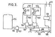
- Figure 3 shows a tractor-mounted system in which dilution takes place; this however is carried out automatically, without the need for any manual mixing and consequent risk of errors or accidents.
- the system of Figure 3 comprises a reservoir 155 for an oil diluent (e.g. diesel fuel) for delivering diluent via a tap 156 to a mechanical pump 157 driven by the tractor power take-off.
- Two containers 158, 159 of generally similar type to that shown in Figure 1 contain concentrated organic liquid pesticide formulations and are connected via couplings 160, 161 to metering pumps 164, 165 which serve to inject pesticide into the diluent stream at 166, 167.
- the diluted pesticidal formulation passes to a boom 168 carrying electrostatic sprayheads 169 of the same type as shown in Figure 1.
- the sprayheads 169 are connected to one high-voltage terminal of a high-voltage generator 170, powered by the tractor battery 171. No provision for varying the output voltage of generator 170 is illustrated, though such may readily be provided if required.
- Metering pumps 164, 165 are also powered from battery 171 via variable resistances 172, 173 mounted on containers 158 and 159, in the same way as battery 22 powers pump 14 in Figure 1.
- the flows from containers 158 and 159 may be directed to separate sprayheads.
- an aqueous liquid pesticide formulation use may be made of the electrostatic system for forming and spraying emulsions described in our copending unpublished UK patent application 8102823 of 30 January,1981 entitled 'Spraying Emulsions'.
- Systems such as that shown in figure 3, containing a separate source of diluent, may conveniently be made to flush pesticide out of the nozzles and liquid delivery system, using pure diluent. The system is thereby cleaned for re-use with different pesticides. Such flashing may be made automatic.
- the signal means it is not necessary that flow through the liquid delivery system be determined uniquely by the signal means carried on the container. It is possible, for example, for the signal means to determine a base value for the flow rate, corresponding to a standard vehicle forward speed. Means may then be supplied to sense the actual forward speed of the spray vehicle and vary the flow rate from ths standard to compensate for variations from the standard forward speed, in such a way that the amount of pesticide delivered per unit area remains constant over a range of forward speeds. Speed may be sensed by the rotation rate of a vehicle wheel, or by doppler sound or radar measurements. It is also possible to provide means for the spray operator to vary the standard flow rate, eg in exceptional circumstances. For example, a crop heavily infested with pests may be usefully sprayed at 150% or 200% of the normal rate; and a lightly infested one at 50 or 75% of the normal rate.
- Means may be provided to detect malfunctioning of the electrostatic sprayheads used in the invention.
- One such possible means is shown schematically in figure 4.
- a high resistance 102 (say 1 megohm) is inserted.
- Means 103 are provided for sensing the potential drop across this resistance. Using a voltage of about 20 KV, and a liquid charging current of about 2 micro amperes per nozzle, the potential drop across resistance 102 will be about 2 volts. If sprayhead 101 becomes wholly or partially blocked, the current will stop or reduce and the voltage will drop correspondingly. If there is a short circuit, e.g. between sprayhead 101 and earthed electrode 104, current and voltage will increase.
- a control circuit 105 is provided to compare the potential drop sensed by means 103 with standard satisfactory limits, and if these are exceeded circuit 105 lights a warning light 106 in the tractor driver's cab. This tells the driver that one sprayhead is not operating correctly (and which it is). In mechanical spraying systems, sprayhead blockages may go undetected for substantial periods, and lead to crop loss through failure to apply correct rates of pesticide.
- a second possible means for detecting malfunctioning is shown in Figure 5.
- a probe 110 adjacent a sprayhead nozzle 111 has a charge induced on it which depends on the charge on-the liquid leaving the nozzle 111, This charge is sensed by a field-effect (high input impedance) transistor 112.
- a circuit 113 is provided to compare the charge sensed by the transistor 112 against an appropriate range of standard values, and if the range is exceeded to light a warning light 114 in the tractor- driver's cab.
- a nozzle blockage will reduce the charge induced on probe 110, as will any reduction in the voltage supplied to nozzle 111.
- signals from detector means of the type shown in Figure 4 or Figure 5 may be combined, and means responsive to variations in the combined signal may be provided to vary the flow through the delivery system until the combined signal is within pre-set limits.
- means responsive to such variations may be provided to vary the voltage from the high potential system until the combined signal is within pre-set.limits.
- Figure 2 is a detail, in vertical section, of an electrostatic sprayhead used in the invention. It comprises a nozzle 60 having a liquid outlet or mouth 64 in the form of an annular gap between an outer hollow cylinder 61 formed from conductive plastics and an inner solid cylinder 62 formed from conductive plastics. Around nozzle 60, and behind the mouth 64, an annular electrode 65 of bare metal is symmetrically disposed.
- the containers of our invention may include a device preventing re-use.
- a device may be of a type that has to be re-set at the factory once the container has been emptied, e.g. a fuse in the lowest part of the container which overheats and blows when no longer covered with liquid. It may be somewhat more complex, eg a device measuring liquid flow-rate out of the container, which, after the container has been emptied, modifies the signal means to cause the control means to stop operation of the delivery system.
- the delivery system may include one or more electrostatic valves of the type dislosed in our European Patent application No 80302767.
- Liquids sprayed by the process of our invention may be solutions, emulsions, or free-flowing suspensions of finely-divided solids in liquid.
- annular nozzles shown in the drawings it is possible to use one or more linear sprayheads, eg of the type shown in our UK Patent 1569707 ( Figures 12-14).
Abstract
Description
- The present invention relates to spraying systems, and more particularly to spraying systems for use in applying agricultural chemicals, e.g. pesticides, to land or to crops or weeds growing therein.
- In nearly every country of the world, agricultural spraying of land or crops is widely carried out, frequently from a vehicle such as a tractor or an aircraft. Spraying is usually carried out using an active ingredient (e.g. a herbicide) dissolved or disposed in a diluent (e.g. oil cr water). Thus, a tractor may carry a spraytank filled with water, into which a concentrated liquid or powder formulation of the active ingredient is poured and mixed prior to spraying.
- This arrangement has drawbacks. Pesticide active ingredients are frequently toxic to man to a greater cr lesser extent, particularly in concentrated form. Thus, in some cases, emptying a concentrated pesticide formulation into a spraytank can represent a hazard, in particular to unskilled or poorly trained operators. It is also possible for such operators to make mistakes in the dilution procedure, by putting in either too little pesticide (perhaps in consequence leaving a crop.unprotected) or too much (which is wasteful and could damage a crop or the environment).
- There is in consequence a need for spraying systems which do not involve dilution of concentrated pesticides by the operator. In such systems, either the pesticide formulation is not diluted at all (as is now sometimes done, for example, in ultra-low volume spraying of insecticides from a rotary atomiser, and has also been proposed for certain electrostatic spraying systems) or it is diluted automatically e.g. by being metered into a stream of diluent from a diluent storage tank carried on the tractor. Now a practical sprayer requires to be able to spray pesticides of several different kinds. Some pesticides are conveniently formulated more concentrated than others, or need to be applied at lower rates. Thus the rate at which liquid flows through the sprayer to the sprayhead generally needs to be controllable. It may of course be controlled manually, by some device or other, but this may sometimes lead to operator error.
- The present invention is particularly (though not solely) applicable to electrostatic agricultural spraying, which has particular advantages. Thus it provides more even cover of plants with much improved cover of under-leaf surfaces; reduces drift and contamination of the environment; and often enables lower rates of pesticide to be applied than are effective with uncharged sprays. It may be found, however, best to vary the applied voltage varied according to the nature of the pesticide formulation it is desired to apply.
- The present invention provides a system for spraying pesticides in which manual dilution (with consequent operator hazard and possibly dilution errors) is avoided and the delivery rate of pesticide to spray nozzles may if desired be completely automatically determined.
- According to the present invention we provide apparatus for spraying of liquid agrochemical formulations from a vehicle which comprises: container coupling means for receiving a container for said liquid; at least one sprayhead for discharging said liquid; a delivery system for conveying liquid from the container via the coupling means to the sprayhead; and flow control means for said delivery system, said flow control means being responsive to signal means carried on the container. In a preferred embodiment, means are provided to charge electrostatically liquid emerging from the sprayhed; and these charging means may also be responsive to signal means carried on the container.
- We further provide, for use in such spraying apparatus a liquid container adapted to be mounted on a vehicle, having a mouth for delivering liquid, coupling means for holding the mouth in fluid-tight engagement with coupling means carried on the vehicle, and carrying signal means disposed to actuate flow control operating means carried on the vehicle.
- The flow control means may take various forms. It may, for example, be a variable valve, for example a mechanical valve, such as a stopcock or iris, operated by electronic control means though an electromagnetic relay. Another suitable type of valve, particularly readily operable by electronic control, is a variable electrostatic valve of the type described in our copending European Patent application no. 80302767. One particularly convenient form cf control means is a variable flow-rate metering pump. Such a pump may suitably be electrically driven, e.g. from an electrical power supply on the vehicle, and its speed is then readily controlled by electrical or electronic means controlling the power or frequency of the electrical supply to the pump. A metering pump, though more complex than a variable valve, can control liquid delivery more accurately since it does not depend on gravity to propel the liquid.
- In one form of the invention, the signal means on the container comprises a coded signal which is sensed by the flow control means and which determines how the flow control means activates the delivery system. It may also deterimine how the charging means is activated. The coded signal may produce a range of effects. It may simply act as an 'on' switch, so that the machine will only work where the signal received has a predetermined value. The system may be designed to provide several different combinations of flow rate through the delivery system and voltage from the high potential source corresponding to different values of the coded signal on the container. The system may also be designed to vary voltage, or flow rate, or both,
- continuously between minimum and maximum values according to corresponding variation in the value of the coded signal (or signals). Coded signals may be provided in various forms, e.g. mechanical, electrical, magnetic or optical.
- The signal means on the container may control the flow control means by providing to it an electrical signal. This electrical signal may be used (either directly or after amplification) to operate the high potential source, or the liquid delivery system, at outputs corresponding to. the magnitude of the signal.
- A specific embodiment of the invention will now be described with reference to the drawing, in which
- Figure 1 is a schematic diagram of a system according to the invention in operation
- Figure 2 is a vertical section through a spray nozzle
- Figure 3 is a schematic diagram of a second type of spraying system according to the invention
- Figure 4 shows diagrammatically a sprayhead malfunction detector circuit
- Figure 5 shows diagrammatically a second type of sprayhead malfunction detector circuit.
- The system is mounted on a tractor (not shown). It comprises a
demountable container 10 of about 25 litres capacity. A male screw-thread coupling 11 on the neck of thecontainer 10 cooperates to give a'liquid-tight seal with corresponding female screw-thread coupling means 12 carried on the tractor and forming part of theliquid distribution system 13.Liquid delivery system 13 leads from coupling means 12 via an electrically operatedmetering pump 14 to a spray boom 15 carrying a number of nozzles 16. The construction of these is shown in more detail in figure 2 . Each nozzle is surrounded by anannular electrode 26 which is earthed. The body of each nozzle is made of electrically-conducting plastic, and is electrically connected via leads 17 to a junction-box 18, which communicates via high-tension lead 19 with one highvoltage output terminal 21 of high-voltage generator 20.Generator 20 is powered from the 12-volt tractor battery 22 via thecontainer 10. - The positive pole of the
tractor battery 22 is connected, viaswitch 23, to acontact 24 carried on the tractor. This abuts acontact 25 on the container, which connects via avariable resistance 26 to acontact 27 on the container abutting acontact 28 carried on the tracter. Contact 28 is connected via lead 29 to an input terminal ofgenerator 20. By a similar arrangement,pump 14 is powered frombattery 22 viacontainer 10. Alead 30 conveys current frombattery 22 viaswitch 23 to a contact 31 carried on the tractor. This abuts acontact 32 on the container, which connects via avariable resistance 36 to acontact 33 on the container which abuts acontact 34 on the tractor. Alead 35 connectscontact 34 to pump 14. - In operation, the
container 10 is supplied from the manufacturer, having been filled with a suitable organic liquid pesticide formulation and sealed under safe factory conditions. At the factory thevariable resistances resistances container 10 is mounted on the tractor, unsealed and coupled to theliquid delivery system 13 viacouplings 11 and 12, ensuring that the four sets of contacts (24,25; 27,28; 31,32; 33,34) are in contact. The tractor is then driven past the crops it is desired to spray, and theswitch 23 closed. This activates thepump 14 and thegenerator 20, the output of both being controlled to the desired degree by control of the current supplied to each, which is a function of the setting ofresistances pump 14, where the spray is charged by direct contact at the potential delivered bygenerator 20. Spray leaving the nozzles 16 breaks up into electrically charged droplets under the action of the electrostatic field between nozzles 16 and earthedelectrodes 26, and is attracted to the plants to be treated. - In the system described above with reference to Figure 1, the contents of
container 10 are sprayed without further dilution. Figure 3 shows a tractor-mounted system in which dilution takes place; this however is carried out automatically, without the need for any manual mixing and consequent risk of errors or accidents. The system of Figure 3 comprises areservoir 155 for an oil diluent (e.g. diesel fuel) for delivering diluent via atap 156 to amechanical pump 157 driven by the tractor power take-off. Twocontainers couplings 160, 161 to metering pumps 164, 165 which serve to inject pesticide into the diluent stream at 166, 167. From here the diluted pesticidal formulation passes to aboom 168 carryingelectrostatic sprayheads 169 of the same type as shown in Figure 1. Thesprayheads 169 are connected to one high-voltage terminal of a high-voltage generator 170, powered by thetractor battery 171. No provision for varying the output voltage of generator 170 is illustrated, though such may readily be provided if required. Metering pumps 164, 165 are also powered frombattery 171 viavariable resistances containers battery 22 powers pump 14 in Figure 1. - In operation, the rate at which pesticide from
containers pumps containers - Systems such as that shown in figure 3, containing a separate source of diluent, may conveniently be made to flush pesticide out of the nozzles and liquid delivery system, using pure diluent. The system is thereby cleaned for re-use with different pesticides. Such flashing may be made automatic.
- In our invention, it is not necessary that flow through the liquid delivery system be determined uniquely by the signal means carried on the container. It is possible, for example, for the signal means to determine a base value for the flow rate, corresponding to a standard vehicle forward speed. Means may then be supplied to sense the actual forward speed of the spray vehicle and vary the flow rate from ths standard to compensate for variations from the standard forward speed, in such a way that the amount of pesticide delivered per unit area remains constant over a range of forward speeds. Speed may be sensed by the rotation rate of a vehicle wheel, or by doppler sound or radar measurements. It is also possible to provide means for the spray operator to vary the standard flow rate, eg in exceptional circumstances. For example, a crop heavily infested with pests may be usefully sprayed at 150% or 200% of the normal rate; and a lightly infested one at 50 or 75% of the normal rate.
- Means may be provided to detect malfunctioning of the electrostatic sprayheads used in the invention. One such possible means is shown schematically in figure 4. In the
lead 100 conveying high potential fromgenerator 99 to sprayhead 101, a high resistance 102 (say 1 megohm) is inserted.Means 103 are provided for sensing the potential drop across this resistance. Using a voltage of about 20 KV, and a liquid charging current of about 2 micro amperes per nozzle, the potential drop acrossresistance 102 will be about 2 volts. Ifsprayhead 101 becomes wholly or partially blocked, the current will stop or reduce and the voltage will drop correspondingly. If there is a short circuit, e.g. betweensprayhead 101 and earthedelectrode 104, current and voltage will increase. Accordingly acontrol circuit 105 is provided to compare the potential drop sensed bymeans 103 with standard satisfactory limits, and if these are exceededcircuit 105 lights awarning light 106 in the tractor driver's cab. This tells the driver that one sprayhead is not operating correctly (and which it is). In mechanical spraying systems, sprayhead blockages may go undetected for substantial periods, and lead to crop loss through failure to apply correct rates of pesticide. A second possible means for detecting malfunctioning is shown in Figure 5. Aprobe 110 adjacent asprayhead nozzle 111 has a charge induced on it which depends on the charge on-the liquid leaving thenozzle 111, This charge is sensed by a field-effect (high input impedance)transistor 112. A circuit 113 is provided to compare the charge sensed by thetransistor 112 against an appropriate range of standard values, and if the range is exceeded to light awarning light 114 in the tractor- driver's cab. Here a nozzle blockage will reduce the charge induced onprobe 110, as will any reduction in the voltage supplied tonozzle 111. - If desired, signals from detector means of the type shown in Figure 4 or Figure 5 (or both) may be combined, and means responsive to variations in the combined signal may be provided to vary the flow through the delivery system until the combined signal is within pre-set limits. Alternatively or additionally, means responsive to such variations may be provided to vary the voltage from the high potential system until the combined signal is within pre-set.limits.
- Figure 2 is a detail, in vertical section, of an electrostatic sprayhead used in the invention. It comprises a
nozzle 60 having a liquid outlet ormouth 64 in the form of an annular gap between an outerhollow cylinder 61 formed from conductive plastics and an innersolid cylinder 62 formed from conductive plastics. Aroundnozzle 60, and behind themouth 64, an annular electrode 65 of bare metal is symmetrically disposed. - As an added safety measure to prevent refilling with concentrated toxic materials by spray operators under potentially hazardous conditions, the containers of our invention may include a device preventing re-use. Such a device may be of a type that has to be re-set at the factory once the container has been emptied, e.g. a fuse in the lowest part of the container which overheats and blows when no longer covered with liquid. It may be somewhat more complex, eg a device measuring liquid flow-rate out of the container, which, after the container has been emptied, modifies the signal means to cause the control means to stop operation of the delivery system.
- If desired, the delivery system may include one or more electrostatic valves of the type dislosed in our European Patent application No 80302767.
- Liquids sprayed by the process of our invention may be solutions, emulsions, or free-flowing suspensions of finely-divided solids in liquid. Instead of the annular nozzles shown in the drawings, it is possible to use one or more linear sprayheads, eg of the type shown in our UK Patent 1569707 (Figures 12-14).
Claims (16)
Priority Applications (1)
| Application Number | Priority Date | Filing Date | Title |
|---|---|---|---|
| AT82300303T ATE19340T1 (en) | 1981-02-12 | 1982-01-21 | AGRICULTURAL LIQUID ATOMIZERS AND RESERVOIRS. |
Applications Claiming Priority (4)
| Application Number | Priority Date | Filing Date | Title |
|---|---|---|---|
| GB8104314 | 1981-02-12 | ||
| GB8104314 | 1981-02-12 | ||
| GB8110543 | 1981-04-03 | ||
| GB8110543 | 1981-04-03 |
Publications (2)
| Publication Number | Publication Date |
|---|---|
| EP0058472A1 true EP0058472A1 (en) | 1982-08-25 |
| EP0058472B1 EP0058472B1 (en) | 1986-04-23 |
Family
ID=26278402
Family Applications (1)
| Application Number | Title | Priority Date | Filing Date |
|---|---|---|---|
| EP82300303A Expired EP0058472B1 (en) | 1981-02-12 | 1982-01-21 | Agricultural spraying apparatus and containers for use therewith |
Country Status (3)
| Country | Link |
|---|---|
| US (1) | US4467961A (en) |
| EP (1) | EP0058472B1 (en) |
| DE (1) | DE3270700D1 (en) |
Cited By (10)
| Publication number | Priority date | Publication date | Assignee | Title |
|---|---|---|---|---|
| EP0086075A1 (en) * | 1982-02-05 | 1983-08-17 | Imperial Chemical Industries Plc | Vehicle mounted spraying system |
| EP0086030A1 (en) * | 1982-02-05 | 1983-08-17 | Imperial Chemical Industries Plc | Sprayhead assembly and system comprising such assembly |
| EP0086029A1 (en) * | 1982-02-05 | 1983-08-17 | Imperial Chemical Industries Plc | Fluid container |
| GB2130123A (en) * | 1982-11-04 | 1984-05-31 | Ici Plc | Malfunction detector for electrostatic spraying apparatus |
| US4467961A (en) * | 1981-02-12 | 1984-08-28 | Imperial Chemical Industries Plc | Container and spraying system |
| WO1985000292A1 (en) * | 1983-07-11 | 1985-01-31 | Imperial Chemical Industries Plc | Fluid delivery apparatus |
| US4580721A (en) * | 1981-02-12 | 1986-04-08 | Imperial Chemical Industries Plc | Fluid container |
| US4975647A (en) * | 1987-06-01 | 1990-12-04 | Nova Biomedical Corporation | Controlling machine operation with respect to consumable accessory units |
| NL1000501C2 (en) * | 1995-06-06 | 1996-12-09 | Greenland Nieuw Vennep Bv | Method and device for feeding a spray liquid to nozzles. |
| CN108289410A (en) * | 2015-09-28 | 2018-07-17 | 精密种植有限责任公司 | System for controlling and monitoring farmland liquid application and device |
Families Citing this family (65)
| Publication number | Priority date | Publication date | Assignee | Title |
|---|---|---|---|---|
| CH658411A5 (en) * | 1982-09-10 | 1986-11-14 | Boschung Mecatronic Ag | ELECTROMAGNETICALLY CONTROLLABLE AND CONTROLLABLE SPRAY VALVE FOR LIQUIDS AND SYSTEM WITH SUCH SPRAY VALVES. |
| US4666089A (en) * | 1982-09-30 | 1987-05-19 | Canadian Patents And Development Limited | Multi-liquid electrostatic spraying apparatus |
| US4630169A (en) * | 1984-09-04 | 1986-12-16 | Exxon Research And Engineering Company | Charge injection device |
| GB8432272D0 (en) * | 1984-12-20 | 1985-01-30 | Ici Plc | Spraying apparatus |
| GB8504254D0 (en) * | 1985-02-19 | 1985-03-20 | Ici Plc | Spraying apparatus |
| GB8525021D0 (en) * | 1985-10-10 | 1985-11-13 | Janock Ltd | Injection sprayers |
| US4809127A (en) * | 1987-08-11 | 1989-02-28 | Ion Systems, Inc. | Self-regulating air ionizing apparatus |
| GB8801602D0 (en) * | 1988-01-25 | 1988-02-24 | Novatech Energy Systems | Apparatus for electrically charging liquid droplets for use in stimulation of plant growth/control of insects |
| US5073709A (en) * | 1991-04-09 | 1991-12-17 | Graco Inc. | Electrostatic spray applicator with two-channel optical monitoring system |
| US5428470A (en) * | 1992-07-17 | 1995-06-27 | Beckman Instruments, Inc. | Modular system and method for an automatic analyzer |
| GB9225098D0 (en) | 1992-12-01 | 1993-01-20 | Coffee Ronald A | Charged droplet spray mixer |
| US6880554B1 (en) | 1992-12-22 | 2005-04-19 | Battelle Memorial Institute | Dispensing device |
| US6105571A (en) | 1992-12-22 | 2000-08-22 | Electrosols, Ltd. | Dispensing device |
| RU2123778C1 (en) * | 1993-03-31 | 1998-12-27 | Текнома | Agricultural movable spraying apparatus |
| GB9406255D0 (en) * | 1994-03-29 | 1994-05-18 | Electrosols Ltd | Dispensing device |
| GB9406171D0 (en) * | 1994-03-29 | 1994-05-18 | Electrosols Ltd | Dispensing device |
| GB9410658D0 (en) * | 1994-05-27 | 1994-07-13 | Electrosols Ltd | Dispensing device |
| US6236907B1 (en) | 1995-05-30 | 2001-05-22 | Ag-Chem Equipment Co., Inc. | System and method for creating agricultural decision and application maps for automated agricultural machines |
| WO1997002898A1 (en) * | 1995-07-11 | 1997-01-30 | Ag-Chem Equipment Co., Inc. | Comprehensive product delivery system |
| US5863497A (en) * | 1996-03-11 | 1999-01-26 | The Proctor & Gamble Company | Electrostatic hand sanitizer |
| US6252129B1 (en) | 1996-07-23 | 2001-06-26 | Electrosols, Ltd. | Dispensing device and method for forming material |
| US7193124B2 (en) | 1997-07-22 | 2007-03-20 | Battelle Memorial Institute | Method for forming material |
| US5831855A (en) * | 1996-09-12 | 1998-11-03 | Kinsman; Guy W. | Monitoring system for electrostatic powder painting industry |
| GB2327895B (en) | 1997-08-08 | 2001-08-08 | Electrosols Ltd | A dispensing device |
| US5971294A (en) * | 1997-12-17 | 1999-10-26 | Agco Corp. | Agricultural application systems with improved spray control |
| US6758423B1 (en) | 1999-09-17 | 2004-07-06 | Nordson Corporation | Spray gun with data device and method of control |
| ES2171132B1 (en) * | 2000-11-16 | 2003-12-16 | Justribo Baradad Antonio | HYDRAULIC SPRAY FLOW REGULATION DEVICE FOR PHYTOSANITARY PRODUCTS WITH INDEPENDENT CONTROL IN NOZZLES ADAPTED TO DIFFERENTIAL DISPLACEMENT SPEED. |
| US6606571B2 (en) * | 2001-10-12 | 2003-08-12 | Deere & Company | Microwave flow sensor for a harvester |
| US6802460B2 (en) * | 2002-03-05 | 2004-10-12 | Microflow Engineering Sa | Method and system for ambient air scenting and disinfecting based on flexible, autonomous liquid atomizer cartridges and an intelligent networking thereof |
| US7387265B2 (en) * | 2002-03-05 | 2008-06-17 | Microwflow Engineering Sa | Method and system for ambient air scenting and disinfecting based on flexible, autonomous liquid atomizer cartridges and an intelligent networking thereof |
| US7503510B2 (en) * | 2002-10-30 | 2009-03-17 | Deere & Company | Sprayer docking station and monitoring system |
| US20050095359A1 (en) * | 2003-10-31 | 2005-05-05 | Nordson Corporation | Hot melt adhesive system and method using machine readable information |
| US20050252930A1 (en) * | 2004-05-11 | 2005-11-17 | Contadini Carl D | Dispensing system, a dispenser and a source of material to be used therewith |
| SE528036C2 (en) * | 2004-05-18 | 2006-08-15 | Lind Finance & Dev Ab | Painting spindle coding |
| GB0411142D0 (en) * | 2004-05-19 | 2004-06-23 | Flasma Ltd | Apparatus for showing moving images in a floor |
| CA2487184C (en) * | 2004-11-05 | 2012-04-10 | Stanislaus Montgomery Shivak | Boom control system |
| US7402798B2 (en) * | 2005-01-18 | 2008-07-22 | Phoenix S&T, Inc. | Apparatus and method for controlling an electrostatically induced liquid spray |
| US7763848B2 (en) * | 2005-01-18 | 2010-07-27 | Phoenix S&T, Inc. | Apparatus and method for controlling an electrostatically induced liquid spray |
| US20070017505A1 (en) * | 2005-07-15 | 2007-01-25 | Lipp Brian A | Dispensing device and method |
| US20090095057A1 (en) * | 2007-10-16 | 2009-04-16 | Phoenix S&T, Inc. | Integrated microfluidic nozzle device for chromatographic sample preparation for mass spectrometry applications |
| WO2009108538A2 (en) * | 2008-02-26 | 2009-09-03 | Phoenix S & T, Inc. | Method and apparatus to increase throughput of liquid chromatography-mass spectrometry |
| US9038923B2 (en) * | 2010-04-05 | 2015-05-26 | Wagner Spray Tech Corporation | Fluid level indicator in an airless fluid sprayer |
| US8919669B2 (en) | 2010-04-05 | 2014-12-30 | Wagner Spray Tech Corporation | Fluid intake assembly for remote fluid source |
| US9604236B2 (en) | 2010-04-05 | 2017-03-28 | Jeffrey E. Sandahl | Fluid intake assembly for a fluid sprayer |
| US8744623B2 (en) | 2011-05-26 | 2014-06-03 | Ecolab Usa Inc. | Timed dispenser and audit system |
| DE102011052030A1 (en) | 2011-07-21 | 2013-01-24 | Inuma Fahrzeug-Service Und Maschinenbau Gmbh | Nozzle unit for e.g. agricultural sprayer, for outpouring e.g. liquid in meadow, has sensor for monitoring flow of liquid, designed as thermal flow monitoring sensor and arranged in casing by which nozzle is coupled with feeding line |
| DE102011052032A1 (en) | 2011-07-21 | 2013-01-24 | Inuma Fahrzeug-Service Und Maschinenbau Gmbh | Adapter element for nozzle unit for exhausting liquid, has sensor for monitoring flow of liquid through nozzle unit, where sensor is formed as thermal flow monitoring sensor or thermal anemometer |
| US20130292493A1 (en) * | 2012-05-01 | 2013-11-07 | Finishing Brands Holdings Inc. | Vent system for a gravity feed spray device |
| ES2523795B1 (en) * | 2013-05-28 | 2015-09-08 | Tallers Gili98, S.L. | Equipment for controlled fertilizer dosing |
| US9766105B2 (en) | 2014-07-02 | 2017-09-19 | Cnh Industrial America Llc | Device and method for detecting blockages in an agricultural sprayer |
| CN109310047A (en) * | 2016-04-28 | 2019-02-05 | 阿哥罗奎梅考斯-德莱万特公司 | Chemicals control and measuring equipment for farm land sterilizing machine |
| US10649556B2 (en) * | 2016-12-09 | 2020-05-12 | Dongguan Chen Da Appliance Co. Ltd. | Control knob for controlling operation of a machine |
| US10726647B2 (en) | 2017-03-13 | 2020-07-28 | Cnh Industrial America Llc | Fault detection system for an agricultural machine |
| WO2018193068A1 (en) * | 2017-04-21 | 2018-10-25 | J. Wagner Gmbh | Electrostatic atomiser for liquids |
| JP7210468B2 (en) * | 2017-04-21 | 2023-01-23 | ジェイ. ワグナー ゲーエムベーハー | Electrostatic atomizer for liquids and method of operating the electrostatic atomizer |
| US11148158B2 (en) * | 2017-06-23 | 2021-10-19 | Deere & Company | Agricultural sprayer with compressed air spray |
| EP3441784B1 (en) * | 2017-08-10 | 2023-12-13 | MSO Messtechnik und Ortung GmbH | Method for detecting, characterization and assessment of the quality of a spray and device for monitoring the quality of spray systems |
| DE102017126350A1 (en) | 2017-11-10 | 2019-05-16 | Amazonen-Werke H. Dreyer Gmbh & Co. Kg | Active ingredient supply system for an agricultural sprayer |
| CN108739760A (en) * | 2018-07-09 | 2018-11-06 | 潘桢 | A kind of spraying device prevented based on agricultural insect pest |
| EP3667920B1 (en) | 2018-12-14 | 2023-05-03 | Defond Electech Co., Ltd | A control knob for controlling operation of a machine |
| CA3133562A1 (en) * | 2019-05-01 | 2020-11-05 | Deere & Company | Systems and methods for precise distribution fluidic agricultural commodities |
| US11457621B2 (en) | 2019-07-12 | 2022-10-04 | Deere & Company | Agricultural sprayer system and method |
| CN112450188A (en) * | 2020-11-20 | 2021-03-09 | 昌河飞机工业(集团)有限责任公司 | Agriculture and forestry sprays liquid medicine monitoring circuit |
| CN112892898B (en) * | 2021-01-15 | 2021-11-23 | 江苏大学 | Electrostatic atomization nozzle capable of controlling jet quantity and jet angle and system thereof |
| JP2023162564A (en) * | 2022-04-27 | 2023-11-09 | ヤンマーホールディングス株式会社 | Control method of spraying machine, control program of spraying machine, and spraying machine |
Citations (8)
| Publication number | Priority date | Publication date | Assignee | Title |
|---|---|---|---|---|
| FR2157527A5 (en) * | 1971-10-18 | 1973-06-01 | Sick Erwin | |
| DE2550930A1 (en) * | 1975-11-13 | 1977-05-26 | Klaus Hackenberger | Woodworking control and alignment appts. using conducting markings - has contact sensing device to scan marking on article surface |
| US4044227A (en) * | 1975-08-07 | 1977-08-23 | The Upjohn Company | Bar code reader |
| DE2731712A1 (en) * | 1976-07-15 | 1978-01-19 | Ici Ltd | ELECTROSTATIC LIQUID SPRAYER |
| US4195672A (en) * | 1978-05-24 | 1980-04-01 | Freeman James F | Portable liquid pesticide transfer assembly |
| EP0011991A1 (en) * | 1978-11-23 | 1980-06-11 | E. Allman & Company Limited | Improvements in or relating to remote control devices |
| GB1569707A (en) * | 1976-07-15 | 1980-06-18 | Ici Ltd | Atomisation of liquids |
| EP0025280A1 (en) * | 1979-09-10 | 1981-03-18 | Imperial Chemical Industries Plc | Electrostatically actuated valve |
Family Cites Families (14)
| Publication number | Priority date | Publication date | Assignee | Title |
|---|---|---|---|---|
| CH447714A (en) * | 1967-03-22 | 1967-11-30 | Huber Robert | Safety device on electromagnetic injection valves of internal combustion engines |
| US4006396A (en) * | 1974-01-18 | 1977-02-01 | Motorola, Inc. | Universal battery charging apparatus |
| US3877645A (en) * | 1974-05-28 | 1975-04-15 | Dickey John Corp | Apparatus for spraying liquid product |
| US4052003A (en) * | 1976-08-06 | 1977-10-04 | Dickey-John Corporation | Liquid spreader control system |
| US4220998A (en) * | 1978-04-24 | 1980-09-02 | Kays Sandra E | Electronic liquid application rate monitoring system |
| CY1287A (en) * | 1978-09-26 | 1985-07-05 | Ici Plc | Electrostatic spraying of liquid |
| US4272019A (en) * | 1978-10-17 | 1981-06-09 | Halaby Jr Samuel A | Fluid sprayer apparatus and method |
| GB2039202A (en) * | 1979-01-12 | 1980-08-06 | Curtis Long Dev Ltd | A control system for an agricultural spraying machine or the like |
| US4357670A (en) * | 1979-03-02 | 1982-11-02 | E. Allman & Company Limited | Devices for testing spraying nozzles |
| US4266262A (en) * | 1979-06-29 | 1981-05-05 | Binks Manufacturing Company | Voltage controlled power supply for electrostatic coating apparatus |
| EP0029301B1 (en) * | 1979-11-19 | 1984-12-12 | Imperial Chemical Industries Plc | Electrostatic spraying apparatus |
| GB2073052B (en) * | 1980-03-20 | 1983-12-07 | Ici Ltd | Electrostatic spraying |
| US4401274A (en) * | 1980-03-20 | 1983-08-30 | Imperial Chemical Industries Plc | Containers for use in electrostatic spraying |
| EP0058472B1 (en) * | 1981-02-12 | 1986-04-23 | Imperial Chemical Industries Plc | Agricultural spraying apparatus and containers for use therewith |
-
1982
- 1982-01-21 EP EP82300303A patent/EP0058472B1/en not_active Expired
- 1982-01-21 DE DE8282300303T patent/DE3270700D1/en not_active Expired
- 1982-02-11 US US06/348,087 patent/US4467961A/en not_active Expired - Fee Related
Patent Citations (8)
| Publication number | Priority date | Publication date | Assignee | Title |
|---|---|---|---|---|
| FR2157527A5 (en) * | 1971-10-18 | 1973-06-01 | Sick Erwin | |
| US4044227A (en) * | 1975-08-07 | 1977-08-23 | The Upjohn Company | Bar code reader |
| DE2550930A1 (en) * | 1975-11-13 | 1977-05-26 | Klaus Hackenberger | Woodworking control and alignment appts. using conducting markings - has contact sensing device to scan marking on article surface |
| DE2731712A1 (en) * | 1976-07-15 | 1978-01-19 | Ici Ltd | ELECTROSTATIC LIQUID SPRAYER |
| GB1569707A (en) * | 1976-07-15 | 1980-06-18 | Ici Ltd | Atomisation of liquids |
| US4195672A (en) * | 1978-05-24 | 1980-04-01 | Freeman James F | Portable liquid pesticide transfer assembly |
| EP0011991A1 (en) * | 1978-11-23 | 1980-06-11 | E. Allman & Company Limited | Improvements in or relating to remote control devices |
| EP0025280A1 (en) * | 1979-09-10 | 1981-03-18 | Imperial Chemical Industries Plc | Electrostatically actuated valve |
Cited By (18)
| Publication number | Priority date | Publication date | Assignee | Title |
|---|---|---|---|---|
| US4580721A (en) * | 1981-02-12 | 1986-04-08 | Imperial Chemical Industries Plc | Fluid container |
| US4467961A (en) * | 1981-02-12 | 1984-08-28 | Imperial Chemical Industries Plc | Container and spraying system |
| US4553702A (en) * | 1982-02-05 | 1985-11-19 | Imperial Chemical Industries Plc | Spraying system |
| EP0086061A1 (en) * | 1982-02-05 | 1983-08-17 | Imperial Chemical Industries Plc | Container with memory |
| EP0086030A1 (en) * | 1982-02-05 | 1983-08-17 | Imperial Chemical Industries Plc | Sprayhead assembly and system comprising such assembly |
| EP0086029A1 (en) * | 1982-02-05 | 1983-08-17 | Imperial Chemical Industries Plc | Fluid container |
| EP0086031A1 (en) * | 1982-02-05 | 1983-08-17 | Imperial Chemical Industries Plc | Spraying system |
| EP0086075A1 (en) * | 1982-02-05 | 1983-08-17 | Imperial Chemical Industries Plc | Vehicle mounted spraying system |
| US4586657A (en) * | 1982-11-04 | 1986-05-06 | Imperial Chemical Industries Plc | Malfunction detector for electrostatic spraying apparatus |
| EP0110524A3 (en) * | 1982-11-04 | 1985-08-21 | Imperial Chemical Industries Plc | Malfunction detector for electrostatic spraying apparatus |
| EP0110524A2 (en) * | 1982-11-04 | 1984-06-13 | Imperial Chemical Industries Plc | Malfunction detector for electrostatic spraying apparatus |
| GB2130123A (en) * | 1982-11-04 | 1984-05-31 | Ici Plc | Malfunction detector for electrostatic spraying apparatus |
| WO1985000292A1 (en) * | 1983-07-11 | 1985-01-31 | Imperial Chemical Industries Plc | Fluid delivery apparatus |
| US4975647A (en) * | 1987-06-01 | 1990-12-04 | Nova Biomedical Corporation | Controlling machine operation with respect to consumable accessory units |
| NL1000501C2 (en) * | 1995-06-06 | 1996-12-09 | Greenland Nieuw Vennep Bv | Method and device for feeding a spray liquid to nozzles. |
| EP0746978A1 (en) * | 1995-06-06 | 1996-12-11 | Greenland Nieuw-Vennep B.V. | Method and apparatus for supplying a spraying liquid to spray heads |
| CN108289410A (en) * | 2015-09-28 | 2018-07-17 | 精密种植有限责任公司 | System for controlling and monitoring farmland liquid application and device |
| CN108289410B (en) * | 2015-09-28 | 2021-09-14 | 精密种植有限责任公司 | System and apparatus for controlling and monitoring liquid application to agricultural fields |
Also Published As
| Publication number | Publication date |
|---|---|
| EP0058472B1 (en) | 1986-04-23 |
| US4467961A (en) | 1984-08-28 |
| DE3270700D1 (en) | 1986-05-28 |
Similar Documents
| Publication | Publication Date | Title |
|---|---|---|
| EP0058472B1 (en) | Agricultural spraying apparatus and containers for use therewith | |
| US4580721A (en) | Fluid container | |
| CA1190630A (en) | Fluid container | |
| EP0086030A1 (en) | Sprayhead assembly and system comprising such assembly | |
| EP0086061B1 (en) | Container with memory | |
| US4121767A (en) | Mobile agricultural sprayer with additive concentration control | |
| EP3481187B1 (en) | Spraying device with flow metering | |
| EP0323205B1 (en) | Apparatus for delivering a liquid | |
| US3917168A (en) | Dispensing apparatus and method | |
| US4401274A (en) | Containers for use in electrostatic spraying | |
| JPH02253871A (en) | Application apparatus of plant- protective compound | |
| CA1187584A (en) | Container and spraying system | |
| GB2093732A (en) | Spraying system | |
| US5502685A (en) | Continuous batch mix sprayer | |
| US5964179A (en) | Method for indicating the extent of land subjected to an agricultural operation | |
| GB2129663A (en) | Spraying unit | |
| EP3269238A1 (en) | Sprayer with flow measurement | |
| GB1590650A (en) | Spray applicator |
Legal Events
| Date | Code | Title | Description |
|---|---|---|---|
| PUAI | Public reference made under article 153(3) epc to a published international application that has entered the european phase |
Free format text: ORIGINAL CODE: 0009012 |
|
| AK | Designated contracting states |
Designated state(s): AT BE CH DE FR GB IT LI LU NL SE |
|
| 17P | Request for examination filed |
Effective date: 19830114 |
|
| GRAA | (expected) grant |
Free format text: ORIGINAL CODE: 0009210 |
|
| AK | Designated contracting states |
Kind code of ref document: B1 Designated state(s): AT BE CH DE FR GB IT LI LU NL SE |
|
| REF | Corresponds to: |
Ref document number: 19340 Country of ref document: AT Date of ref document: 19860515 Kind code of ref document: T |
|
| ITF | It: translation for a ep patent filed |
Owner name: BARZANO' E ZANARDO MILANO S.P.A. |
|
| REF | Corresponds to: |
Ref document number: 3270700 Country of ref document: DE Date of ref document: 19860528 |
|
| ET | Fr: translation filed | ||
| PLBE | No opposition filed within time limit |
Free format text: ORIGINAL CODE: 0009261 |
|
| STAA | Information on the status of an ep patent application or granted ep patent |
Free format text: STATUS: NO OPPOSITION FILED WITHIN TIME LIMIT |
|
| 26N | No opposition filed | ||
| PGFP | Annual fee paid to national office [announced via postgrant information from national office to epo] |
Ref country code: NL Payment date: 19890131 Year of fee payment: 11 |
|
| ITTA | It: last paid annual fee | ||
| PGFP | Annual fee paid to national office [announced via postgrant information from national office to epo] |
Ref country code: AT Payment date: 19901210 Year of fee payment: 10 Ref country code: FR Payment date: 19901210 Year of fee payment: 10 |
|
| PGFP | Annual fee paid to national office [announced via postgrant information from national office to epo] |
Ref country code: CH Payment date: 19901217 Year of fee payment: 10 |
|
| PGFP | Annual fee paid to national office [announced via postgrant information from national office to epo] |
Ref country code: SE Payment date: 19901220 Year of fee payment: 10 |
|
| PGFP | Annual fee paid to national office [announced via postgrant information from national office to epo] |
Ref country code: BE Payment date: 19901221 Year of fee payment: 10 Ref country code: GB Payment date: 19901221 Year of fee payment: 10 |
|
| PGFP | Annual fee paid to national office [announced via postgrant information from national office to epo] |
Ref country code: DE Payment date: 19901231 Year of fee payment: 10 |
|
| PGFP | Annual fee paid to national office [announced via postgrant information from national office to epo] |
Ref country code: LU Payment date: 19910108 Year of fee payment: 10 |
|
| EPTA | Lu: last paid annual fee | ||
| PG25 | Lapsed in a contracting state [announced via postgrant information from national office to epo] |
Ref country code: GB Effective date: 19920121 Ref country code: AT Effective date: 19920121 Ref country code: LU Free format text: LAPSE BECAUSE OF NON-PAYMENT OF DUE FEES Effective date: 19920121 |
|
| PG25 | Lapsed in a contracting state [announced via postgrant information from national office to epo] |
Ref country code: SE Effective date: 19920122 |
|
| PG25 | Lapsed in a contracting state [announced via postgrant information from national office to epo] |
Ref country code: LI Effective date: 19920131 Ref country code: CH Effective date: 19920131 Ref country code: BE Effective date: 19920131 |
|
| BERE | Be: lapsed |
Owner name: IMPERIAL CHEMICAL INDUSTRIES P.L.C. Effective date: 19920131 |
|
| PG25 | Lapsed in a contracting state [announced via postgrant information from national office to epo] |
Ref country code: NL Effective date: 19920801 |
|
| NLV4 | Nl: lapsed or anulled due to non-payment of the annual fee | ||
| REG | Reference to a national code |
Ref country code: GB Ref legal event code: PCNP |
|
| PG25 | Lapsed in a contracting state [announced via postgrant information from national office to epo] |
Ref country code: FR Effective date: 19920930 |
|
| REG | Reference to a national code |
Ref country code: CH Ref legal event code: PL |
|
| PG25 | Lapsed in a contracting state [announced via postgrant information from national office to epo] |
Ref country code: DE Effective date: 19921001 |
|
| REG | Reference to a national code |
Ref country code: FR Ref legal event code: ST |
|
| EUG | Se: european patent has lapsed |
Ref document number: 82300303.3 Effective date: 19920806 |