CN101582983B - Recording medium and method, reproduction apparatus and method, program and integrated circuit - Google Patents
Recording medium and method, reproduction apparatus and method, program and integrated circuit Download PDFInfo
- Publication number
- CN101582983B CN101582983B CN200910146304.8A CN200910146304A CN101582983B CN 101582983 B CN101582983 B CN 101582983B CN 200910146304 A CN200910146304 A CN 200910146304A CN 101582983 B CN101582983 B CN 101582983B
- Authority
- CN
- China
- Prior art keywords
- cropping
- window
- graphics plane
- graphic object
- cutting
- Prior art date
- Legal status (The legal status is an assumption and is not a legal conclusion. Google has not performed a legal analysis and makes no representation as to the accuracy of the status listed.)
- Expired - Fee Related
Links
- 238000000034 method Methods 0.000 title claims description 36
- 239000000872 buffer Substances 0.000 claims description 128
- 238000005520 cutting process Methods 0.000 claims description 53
- 230000008569 process Effects 0.000 claims description 21
- 238000012545 processing Methods 0.000 claims description 8
- 230000015654 memory Effects 0.000 abstract description 12
- 238000009877 rendering Methods 0.000 abstract 1
- 230000000694 effects Effects 0.000 description 27
- 230000006870 function Effects 0.000 description 20
- 238000012546 transfer Methods 0.000 description 17
- 230000005540 biological transmission Effects 0.000 description 15
- 239000012634 fragment Substances 0.000 description 15
- 238000004519 manufacturing process Methods 0.000 description 14
- 238000011084 recovery Methods 0.000 description 14
- 101000608720 Helianthus annuus 10 kDa late embryogenesis abundant protein Proteins 0.000 description 11
- 230000006837 decompression Effects 0.000 description 11
- 238000006243 chemical reaction Methods 0.000 description 10
- 238000003860 storage Methods 0.000 description 10
- 238000009966 trimming Methods 0.000 description 8
- 230000008859 change Effects 0.000 description 7
- 230000015572 biosynthetic process Effects 0.000 description 6
- 238000007726 management method Methods 0.000 description 6
- 238000005096 rolling process Methods 0.000 description 6
- 230000003139 buffering effect Effects 0.000 description 5
- 230000006835 compression Effects 0.000 description 5
- 238000007906 compression Methods 0.000 description 5
- 230000002093 peripheral effect Effects 0.000 description 5
- 230000004075 alteration Effects 0.000 description 4
- 238000010276 construction Methods 0.000 description 4
- 238000010586 diagram Methods 0.000 description 4
- 238000005516 engineering process Methods 0.000 description 4
- 230000002452 interceptive effect Effects 0.000 description 4
- OAICVXFJPJFONN-UHFFFAOYSA-N Phosphorus Chemical compound [P] OAICVXFJPJFONN-UHFFFAOYSA-N 0.000 description 3
- 238000000354 decomposition reaction Methods 0.000 description 3
- 230000001815 facial effect Effects 0.000 description 3
- 238000001914 filtration Methods 0.000 description 3
- 101000623061 Drosophila melanogaster 40S ribosomal protein S26 Proteins 0.000 description 2
- 101000608734 Helianthus annuus 11 kDa late embryogenesis abundant protein Proteins 0.000 description 2
- 239000003086 colorant Substances 0.000 description 2
- 238000004891 communication Methods 0.000 description 2
- 238000005034 decoration Methods 0.000 description 2
- 238000000605 extraction Methods 0.000 description 2
- 230000008676 import Effects 0.000 description 2
- 239000000463 material Substances 0.000 description 2
- 239000000203 mixture Substances 0.000 description 2
- 230000004048 modification Effects 0.000 description 2
- 238000012986 modification Methods 0.000 description 2
- 230000001151 other effect Effects 0.000 description 2
- 230000004044 response Effects 0.000 description 2
- 101100190466 Caenorhabditis elegans pid-3 gene Proteins 0.000 description 1
- 241001269238 Data Species 0.000 description 1
- 238000012356 Product development Methods 0.000 description 1
- 238000013461 design Methods 0.000 description 1
- 238000011161 development Methods 0.000 description 1
- 230000018109 developmental process Effects 0.000 description 1
- 230000006872 improvement Effects 0.000 description 1
- 230000010365 information processing Effects 0.000 description 1
- 238000003780 insertion Methods 0.000 description 1
- 230000037431 insertion Effects 0.000 description 1
- 230000006386 memory function Effects 0.000 description 1
- 230000008520 organization Effects 0.000 description 1
- 230000000704 physical effect Effects 0.000 description 1
- 238000004080 punching Methods 0.000 description 1
- 230000001105 regulatory effect Effects 0.000 description 1
- 230000011218 segmentation Effects 0.000 description 1
- 239000004065 semiconductor Substances 0.000 description 1
- GOLXNESZZPUPJE-UHFFFAOYSA-N spiromesifen Chemical compound CC1=CC(C)=CC(C)=C1C(C(O1)=O)=C(OC(=O)CC(C)(C)C)C11CCCC1 GOLXNESZZPUPJE-UHFFFAOYSA-N 0.000 description 1
- 239000000758 substrate Substances 0.000 description 1
- 230000007704 transition Effects 0.000 description 1
- 238000013519 translation Methods 0.000 description 1
- 230000007306 turnover Effects 0.000 description 1
Images


Classifications
-
- G—PHYSICS
- G11—INFORMATION STORAGE
- G11B—INFORMATION STORAGE BASED ON RELATIVE MOVEMENT BETWEEN RECORD CARRIER AND TRANSDUCER
- G11B27/00—Editing; Indexing; Addressing; Timing or synchronising; Monitoring; Measuring tape travel
- G11B27/10—Indexing; Addressing; Timing or synchronising; Measuring tape travel
-
- G—PHYSICS
- G09—EDUCATION; CRYPTOGRAPHY; DISPLAY; ADVERTISING; SEALS
- G09G—ARRANGEMENTS OR CIRCUITS FOR CONTROL OF INDICATING DEVICES USING STATIC MEANS TO PRESENT VARIABLE INFORMATION
- G09G5/00—Control arrangements or circuits for visual indicators common to cathode-ray tube indicators and other visual indicators
- G09G5/36—Control arrangements or circuits for visual indicators common to cathode-ray tube indicators and other visual indicators characterised by the display of a graphic pattern, e.g. using an all-points-addressable [APA] memory
- G09G5/363—Graphics controllers
-
- G—PHYSICS
- G11—INFORMATION STORAGE
- G11B—INFORMATION STORAGE BASED ON RELATIVE MOVEMENT BETWEEN RECORD CARRIER AND TRANSDUCER
- G11B20/00—Signal processing not specific to the method of recording or reproducing; Circuits therefor
- G11B20/10—Digital recording or reproducing
-
- G—PHYSICS
- G11—INFORMATION STORAGE
- G11B—INFORMATION STORAGE BASED ON RELATIVE MOVEMENT BETWEEN RECORD CARRIER AND TRANSDUCER
- G11B20/00—Signal processing not specific to the method of recording or reproducing; Circuits therefor
- G11B20/10—Digital recording or reproducing
- G11B20/10527—Audio or video recording; Data buffering arrangements
-
- G—PHYSICS
- G11—INFORMATION STORAGE
- G11B—INFORMATION STORAGE BASED ON RELATIVE MOVEMENT BETWEEN RECORD CARRIER AND TRANSDUCER
- G11B20/00—Signal processing not specific to the method of recording or reproducing; Circuits therefor
- G11B20/10—Digital recording or reproducing
- G11B20/12—Formatting, e.g. arrangement of data block or words on the record carriers
-
- G—PHYSICS
- G11—INFORMATION STORAGE
- G11B—INFORMATION STORAGE BASED ON RELATIVE MOVEMENT BETWEEN RECORD CARRIER AND TRANSDUCER
- G11B20/00—Signal processing not specific to the method of recording or reproducing; Circuits therefor
- G11B20/10—Digital recording or reproducing
- G11B20/14—Digital recording or reproducing using self-clocking codes
-
- G—PHYSICS
- G11—INFORMATION STORAGE
- G11B—INFORMATION STORAGE BASED ON RELATIVE MOVEMENT BETWEEN RECORD CARRIER AND TRANSDUCER
- G11B27/00—Editing; Indexing; Addressing; Timing or synchronising; Monitoring; Measuring tape travel
- G11B27/02—Editing, e.g. varying the order of information signals recorded on, or reproduced from, record carriers
- G11B27/031—Electronic editing of digitised analogue information signals, e.g. audio or video signals
- G11B27/034—Electronic editing of digitised analogue information signals, e.g. audio or video signals on discs
-
- G—PHYSICS
- G11—INFORMATION STORAGE
- G11B—INFORMATION STORAGE BASED ON RELATIVE MOVEMENT BETWEEN RECORD CARRIER AND TRANSDUCER
- G11B27/00—Editing; Indexing; Addressing; Timing or synchronising; Monitoring; Measuring tape travel
- G11B27/10—Indexing; Addressing; Timing or synchronising; Measuring tape travel
- G11B27/102—Programmed access in sequence to addressed parts of tracks of operating record carriers
- G11B27/105—Programmed access in sequence to addressed parts of tracks of operating record carriers of operating discs
-
- G—PHYSICS
- G11—INFORMATION STORAGE
- G11B—INFORMATION STORAGE BASED ON RELATIVE MOVEMENT BETWEEN RECORD CARRIER AND TRANSDUCER
- G11B27/00—Editing; Indexing; Addressing; Timing or synchronising; Monitoring; Measuring tape travel
- G11B27/10—Indexing; Addressing; Timing or synchronising; Measuring tape travel
- G11B27/19—Indexing; Addressing; Timing or synchronising; Measuring tape travel by using information detectable on the record carrier
- G11B27/28—Indexing; Addressing; Timing or synchronising; Measuring tape travel by using information detectable on the record carrier by using information signals recorded by the same method as the main recording
- G11B27/32—Indexing; Addressing; Timing or synchronising; Measuring tape travel by using information detectable on the record carrier by using information signals recorded by the same method as the main recording on separate auxiliary tracks of the same or an auxiliary record carrier
- G11B27/327—Table of contents
- G11B27/329—Table of contents on a disc [VTOC]
-
- G—PHYSICS
- G11—INFORMATION STORAGE
- G11B—INFORMATION STORAGE BASED ON RELATIVE MOVEMENT BETWEEN RECORD CARRIER AND TRANSDUCER
- G11B27/00—Editing; Indexing; Addressing; Timing or synchronising; Monitoring; Measuring tape travel
- G11B27/10—Indexing; Addressing; Timing or synchronising; Measuring tape travel
- G11B27/34—Indicating arrangements
-
- H—ELECTRICITY
- H04—ELECTRIC COMMUNICATION TECHNIQUE
- H04N—PICTORIAL COMMUNICATION, e.g. TELEVISION
- H04N21/00—Selective content distribution, e.g. interactive television or video on demand [VOD]
- H04N21/20—Servers specifically adapted for the distribution of content, e.g. VOD servers; Operations thereof
- H04N21/23—Processing of content or additional data; Elementary server operations; Server middleware
- H04N21/235—Processing of additional data, e.g. scrambling of additional data or processing content descriptors
-
- H—ELECTRICITY
- H04—ELECTRIC COMMUNICATION TECHNIQUE
- H04N—PICTORIAL COMMUNICATION, e.g. TELEVISION
- H04N21/00—Selective content distribution, e.g. interactive television or video on demand [VOD]
- H04N21/20—Servers specifically adapted for the distribution of content, e.g. VOD servers; Operations thereof
- H04N21/23—Processing of content or additional data; Elementary server operations; Server middleware
- H04N21/236—Assembling of a multiplex stream, e.g. transport stream, by combining a video stream with other content or additional data, e.g. inserting a URL [Uniform Resource Locator] into a video stream, multiplexing software data into a video stream; Remultiplexing of multiplex streams; Insertion of stuffing bits into the multiplex stream, e.g. to obtain a constant bit-rate; Assembling of a packetised elementary stream
- H04N21/23614—Multiplexing of additional data and video streams
-
- H—ELECTRICITY
- H04—ELECTRIC COMMUNICATION TECHNIQUE
- H04N—PICTORIAL COMMUNICATION, e.g. TELEVISION
- H04N21/00—Selective content distribution, e.g. interactive television or video on demand [VOD]
- H04N21/40—Client devices specifically adapted for the reception of or interaction with content, e.g. set-top-box [STB]; Operations thereof
- H04N21/41—Structure of client; Structure of client peripherals
- H04N21/4104—Peripherals receiving signals from specially adapted client devices
- H04N21/4112—Peripherals receiving signals from specially adapted client devices having fewer capabilities than the client, e.g. thin client having less processing power or no tuning capabilities
-
- H—ELECTRICITY
- H04—ELECTRIC COMMUNICATION TECHNIQUE
- H04N—PICTORIAL COMMUNICATION, e.g. TELEVISION
- H04N21/00—Selective content distribution, e.g. interactive television or video on demand [VOD]
- H04N21/40—Client devices specifically adapted for the reception of or interaction with content, e.g. set-top-box [STB]; Operations thereof
- H04N21/41—Structure of client; Structure of client peripherals
- H04N21/426—Internal components of the client ; Characteristics thereof
- H04N21/42646—Internal components of the client ; Characteristics thereof for reading from or writing on a non-volatile solid state storage medium, e.g. DVD, CD-ROM
-
- H—ELECTRICITY
- H04—ELECTRIC COMMUNICATION TECHNIQUE
- H04N—PICTORIAL COMMUNICATION, e.g. TELEVISION
- H04N21/00—Selective content distribution, e.g. interactive television or video on demand [VOD]
- H04N21/40—Client devices specifically adapted for the reception of or interaction with content, e.g. set-top-box [STB]; Operations thereof
- H04N21/43—Processing of content or additional data, e.g. demultiplexing additional data from a digital video stream; Elementary client operations, e.g. monitoring of home network or synchronising decoder's clock; Client middleware
- H04N21/4302—Content synchronisation processes, e.g. decoder synchronisation
- H04N21/4307—Synchronising the rendering of multiple content streams or additional data on devices, e.g. synchronisation of audio on a mobile phone with the video output on the TV screen
- H04N21/43074—Synchronising the rendering of multiple content streams or additional data on devices, e.g. synchronisation of audio on a mobile phone with the video output on the TV screen of additional data with content streams on the same device, e.g. of EPG data or interactive icon with a TV program
-
- H—ELECTRICITY
- H04—ELECTRIC COMMUNICATION TECHNIQUE
- H04N—PICTORIAL COMMUNICATION, e.g. TELEVISION
- H04N21/00—Selective content distribution, e.g. interactive television or video on demand [VOD]
- H04N21/40—Client devices specifically adapted for the reception of or interaction with content, e.g. set-top-box [STB]; Operations thereof
- H04N21/43—Processing of content or additional data, e.g. demultiplexing additional data from a digital video stream; Elementary client operations, e.g. monitoring of home network or synchronising decoder's clock; Client middleware
- H04N21/431—Generation of visual interfaces for content selection or interaction; Content or additional data rendering
- H04N21/4312—Generation of visual interfaces for content selection or interaction; Content or additional data rendering involving specific graphical features, e.g. screen layout, special fonts or colors, blinking icons, highlights or animations
- H04N21/4314—Generation of visual interfaces for content selection or interaction; Content or additional data rendering involving specific graphical features, e.g. screen layout, special fonts or colors, blinking icons, highlights or animations for fitting data in a restricted space on the screen, e.g. EPG data in a rectangular grid
-
- H—ELECTRICITY
- H04—ELECTRIC COMMUNICATION TECHNIQUE
- H04N—PICTORIAL COMMUNICATION, e.g. TELEVISION
- H04N21/00—Selective content distribution, e.g. interactive television or video on demand [VOD]
- H04N21/40—Client devices specifically adapted for the reception of or interaction with content, e.g. set-top-box [STB]; Operations thereof
- H04N21/43—Processing of content or additional data, e.g. demultiplexing additional data from a digital video stream; Elementary client operations, e.g. monitoring of home network or synchronising decoder's clock; Client middleware
- H04N21/434—Disassembling of a multiplex stream, e.g. demultiplexing audio and video streams, extraction of additional data from a video stream; Remultiplexing of multiplex streams; Extraction or processing of SI; Disassembling of packetised elementary stream
-
- H—ELECTRICITY
- H04—ELECTRIC COMMUNICATION TECHNIQUE
- H04N—PICTORIAL COMMUNICATION, e.g. TELEVISION
- H04N21/00—Selective content distribution, e.g. interactive television or video on demand [VOD]
- H04N21/40—Client devices specifically adapted for the reception of or interaction with content, e.g. set-top-box [STB]; Operations thereof
- H04N21/43—Processing of content or additional data, e.g. demultiplexing additional data from a digital video stream; Elementary client operations, e.g. monitoring of home network or synchronising decoder's clock; Client middleware
- H04N21/435—Processing of additional data, e.g. decrypting of additional data, reconstructing software from modules extracted from the transport stream
-
- H—ELECTRICITY
- H04—ELECTRIC COMMUNICATION TECHNIQUE
- H04N—PICTORIAL COMMUNICATION, e.g. TELEVISION
- H04N21/00—Selective content distribution, e.g. interactive television or video on demand [VOD]
- H04N21/40—Client devices specifically adapted for the reception of or interaction with content, e.g. set-top-box [STB]; Operations thereof
- H04N21/43—Processing of content or additional data, e.g. demultiplexing additional data from a digital video stream; Elementary client operations, e.g. monitoring of home network or synchronising decoder's clock; Client middleware
- H04N21/442—Monitoring of processes or resources, e.g. detecting the failure of a recording device, monitoring the downstream bandwidth, the number of times a movie has been viewed, the storage space available from the internal hard disk
-
- H—ELECTRICITY
- H04—ELECTRIC COMMUNICATION TECHNIQUE
- H04N—PICTORIAL COMMUNICATION, e.g. TELEVISION
- H04N21/00—Selective content distribution, e.g. interactive television or video on demand [VOD]
- H04N21/40—Client devices specifically adapted for the reception of or interaction with content, e.g. set-top-box [STB]; Operations thereof
- H04N21/47—End-user applications
- H04N21/488—Data services, e.g. news ticker
- H04N21/4884—Data services, e.g. news ticker for displaying subtitles
-
- H—ELECTRICITY
- H04—ELECTRIC COMMUNICATION TECHNIQUE
- H04N—PICTORIAL COMMUNICATION, e.g. TELEVISION
- H04N21/00—Selective content distribution, e.g. interactive television or video on demand [VOD]
- H04N21/80—Generation or processing of content or additional data by content creator independently of the distribution process; Content per se
- H04N21/81—Monomedia components thereof
- H04N21/8146—Monomedia components thereof involving graphical data, e.g. 3D object, 2D graphics
-
- H—ELECTRICITY
- H04—ELECTRIC COMMUNICATION TECHNIQUE
- H04N—PICTORIAL COMMUNICATION, e.g. TELEVISION
- H04N7/00—Television systems
- H04N7/16—Analogue secrecy systems; Analogue subscription systems
- H04N7/162—Authorising the user terminal, e.g. by paying; Registering the use of a subscription channel, e.g. billing
- H04N7/163—Authorising the user terminal, e.g. by paying; Registering the use of a subscription channel, e.g. billing by receiver means only
-
- H—ELECTRICITY
- H04—ELECTRIC COMMUNICATION TECHNIQUE
- H04N—PICTORIAL COMMUNICATION, e.g. TELEVISION
- H04N9/00—Details of colour television systems
- H04N9/79—Processing of colour television signals in connection with recording
- H04N9/80—Transformation of the television signal for recording, e.g. modulation, frequency changing; Inverse transformation for playback
- H04N9/82—Transformation of the television signal for recording, e.g. modulation, frequency changing; Inverse transformation for playback the individual colour picture signal components being recorded simultaneously only
- H04N9/8205—Transformation of the television signal for recording, e.g. modulation, frequency changing; Inverse transformation for playback the individual colour picture signal components being recorded simultaneously only involving the multiplexing of an additional signal and the colour video signal
-
- G—PHYSICS
- G09—EDUCATION; CRYPTOGRAPHY; DISPLAY; ADVERTISING; SEALS
- G09G—ARRANGEMENTS OR CIRCUITS FOR CONTROL OF INDICATING DEVICES USING STATIC MEANS TO PRESENT VARIABLE INFORMATION
- G09G2340/00—Aspects of display data processing
- G09G2340/12—Overlay of images, i.e. displayed pixel being the result of switching between the corresponding input pixels
- G09G2340/125—Overlay of images, i.e. displayed pixel being the result of switching between the corresponding input pixels wherein one of the images is motion video
-
- G—PHYSICS
- G11—INFORMATION STORAGE
- G11B—INFORMATION STORAGE BASED ON RELATIVE MOVEMENT BETWEEN RECORD CARRIER AND TRANSDUCER
- G11B20/00—Signal processing not specific to the method of recording or reproducing; Circuits therefor
- G11B20/10—Digital recording or reproducing
- G11B20/12—Formatting, e.g. arrangement of data block or words on the record carriers
- G11B2020/1264—Formatting, e.g. arrangement of data block or words on the record carriers wherein the formatting concerns a specific kind of data
- G11B2020/1288—Formatting by padding empty spaces with dummy data, e.g. writing zeroes or random data when de-icing optical discs
-
- G—PHYSICS
- G11—INFORMATION STORAGE
- G11B—INFORMATION STORAGE BASED ON RELATIVE MOVEMENT BETWEEN RECORD CARRIER AND TRANSDUCER
- G11B2220/00—Record carriers by type
- G11B2220/20—Disc-shaped record carriers
-
- G—PHYSICS
- G11—INFORMATION STORAGE
- G11B—INFORMATION STORAGE BASED ON RELATIVE MOVEMENT BETWEEN RECORD CARRIER AND TRANSDUCER
- G11B2220/00—Record carriers by type
- G11B2220/20—Disc-shaped record carriers
- G11B2220/21—Disc-shaped record carriers characterised in that the disc is of read-only, rewritable, or recordable type
- G11B2220/213—Read-only discs
-
- G—PHYSICS
- G11—INFORMATION STORAGE
- G11B—INFORMATION STORAGE BASED ON RELATIVE MOVEMENT BETWEEN RECORD CARRIER AND TRANSDUCER
- G11B2220/00—Record carriers by type
- G11B2220/20—Disc-shaped record carriers
- G11B2220/25—Disc-shaped record carriers characterised in that the disc is based on a specific recording technology
- G11B2220/2537—Optical discs
- G11B2220/2541—Blu-ray discs; Blue laser DVR discs
-
- H—ELECTRICITY
- H04—ELECTRIC COMMUNICATION TECHNIQUE
- H04N—PICTORIAL COMMUNICATION, e.g. TELEVISION
- H04N21/00—Selective content distribution, e.g. interactive television or video on demand [VOD]
- H04N21/40—Client devices specifically adapted for the reception of or interaction with content, e.g. set-top-box [STB]; Operations thereof
- H04N21/47—End-user applications
- H04N21/488—Data services, e.g. news ticker
-
- H—ELECTRICITY
- H04—ELECTRIC COMMUNICATION TECHNIQUE
- H04N—PICTORIAL COMMUNICATION, e.g. TELEVISION
- H04N5/00—Details of television systems
- H04N5/44—Receiver circuitry for the reception of television signals according to analogue transmission standards
- H04N5/445—Receiver circuitry for the reception of television signals according to analogue transmission standards for displaying additional information
- H04N5/44504—Circuit details of the additional information generator, e.g. details of the character or graphics signal generator, overlay mixing circuits
-
- H—ELECTRICITY
- H04—ELECTRIC COMMUNICATION TECHNIQUE
- H04N—PICTORIAL COMMUNICATION, e.g. TELEVISION
- H04N5/00—Details of television systems
- H04N5/76—Television signal recording
- H04N5/765—Interface circuits between an apparatus for recording and another apparatus
- H04N5/775—Interface circuits between an apparatus for recording and another apparatus between a recording apparatus and a television receiver
-
- H—ELECTRICITY
- H04—ELECTRIC COMMUNICATION TECHNIQUE
- H04N—PICTORIAL COMMUNICATION, e.g. TELEVISION
- H04N5/00—Details of television systems
- H04N5/76—Television signal recording
- H04N5/78—Television signal recording using magnetic recording
- H04N5/782—Television signal recording using magnetic recording on tape
- H04N5/783—Adaptations for reproducing at a rate different from the recording rate
-
- H—ELECTRICITY
- H04—ELECTRIC COMMUNICATION TECHNIQUE
- H04N—PICTORIAL COMMUNICATION, e.g. TELEVISION
- H04N5/00—Details of television systems
- H04N5/76—Television signal recording
- H04N5/84—Television signal recording using optical recording
- H04N5/85—Television signal recording using optical recording on discs or drums
-
- H—ELECTRICITY
- H04—ELECTRIC COMMUNICATION TECHNIQUE
- H04N—PICTORIAL COMMUNICATION, e.g. TELEVISION
- H04N9/00—Details of colour television systems
- H04N9/79—Processing of colour television signals in connection with recording
- H04N9/80—Transformation of the television signal for recording, e.g. modulation, frequency changing; Inverse transformation for playback
- H04N9/804—Transformation of the television signal for recording, e.g. modulation, frequency changing; Inverse transformation for playback involving pulse code modulation of the colour picture signal components
- H04N9/8042—Transformation of the television signal for recording, e.g. modulation, frequency changing; Inverse transformation for playback involving pulse code modulation of the colour picture signal components involving data reduction
-
- H—ELECTRICITY
- H04—ELECTRIC COMMUNICATION TECHNIQUE
- H04N—PICTORIAL COMMUNICATION, e.g. TELEVISION
- H04N9/00—Details of colour television systems
- H04N9/79—Processing of colour television signals in connection with recording
- H04N9/80—Transformation of the television signal for recording, e.g. modulation, frequency changing; Inverse transformation for playback
- H04N9/804—Transformation of the television signal for recording, e.g. modulation, frequency changing; Inverse transformation for playback involving pulse code modulation of the colour picture signal components
- H04N9/806—Transformation of the television signal for recording, e.g. modulation, frequency changing; Inverse transformation for playback involving pulse code modulation of the colour picture signal components with processing of the sound signal
- H04N9/8063—Transformation of the television signal for recording, e.g. modulation, frequency changing; Inverse transformation for playback involving pulse code modulation of the colour picture signal components with processing of the sound signal using time division multiplex of the PCM audio and PCM video signals
-
- H—ELECTRICITY
- H04—ELECTRIC COMMUNICATION TECHNIQUE
- H04N—PICTORIAL COMMUNICATION, e.g. TELEVISION
- H04N9/00—Details of colour television systems
- H04N9/79—Processing of colour television signals in connection with recording
- H04N9/80—Transformation of the television signal for recording, e.g. modulation, frequency changing; Inverse transformation for playback
- H04N9/82—Transformation of the television signal for recording, e.g. modulation, frequency changing; Inverse transformation for playback the individual colour picture signal components being recorded simultaneously only
- H04N9/8205—Transformation of the television signal for recording, e.g. modulation, frequency changing; Inverse transformation for playback the individual colour picture signal components being recorded simultaneously only involving the multiplexing of an additional signal and the colour video signal
- H04N9/8227—Transformation of the television signal for recording, e.g. modulation, frequency changing; Inverse transformation for playback the individual colour picture signal components being recorded simultaneously only involving the multiplexing of an additional signal and the colour video signal the additional signal being at least another television signal
Abstract
A recording medium storing an AVClip structured by multiplexing video stream and a graphics stream. The graphics stream represents a moving picture made of a plurality of pictures, and the graphics stream includes graphics data representing graphics to be combined with the pictures. The graphics stream also includes window information (WDS) that specifies a window for rendering the graphics, and that indicates a width, a height and a position of the window on a plane which is a plane memory of a reproduction apparatus that combines the graphics with the pictures.
Description
The application is for dividing an application, its original application is the patent application of submitting on October 28th, 2005 (international filing date on April 27th, 2004) to Patent Office of the People's Republic of China, application number is 200480011555.0, and denomination of invention is " recording medium and method, transcriber and method, program and integrated circuit ".
Technical field
The present invention relates to a kind of recording medium, as BD-ROM, and renderer device, particularly by reproducing digital stream, adding the technology of captions, this digital stream flows (video stream) by multiplex video and graphical stream (graphics stream) forms.
By implementing the background technology of graphical stream realization, be for allowing the people in different language region to appreciate the important technology of the film producing with the language beyond their mother tongue.The conventional example that adds caption technology is the memory allocation scheme for the pixel buffer (Pixel Buffer) of ETSI EN 300743 standards based on being proposed by European communication standard association (EurpeanTelecommunications Standards Institute (ETSI)).Pixel buffer is the memory that stores decompression figure for interim, and transcriber writes the figure in pixel buffer in the display-memory that is called as graphics plane (Graphics Plane), therefore shows this figure.In memory allocation scheme, in pixel buffer, comprise the definition of region (region), and part decompression figure that should region is written in graphics plane.For example, when captions " Goodbye " are included in pixel buffer, and define the position in this region and size to comprise " Go " part, " Go " part is written in graphics plane and is presented on phosphor screen.Equally.When the definition position in this region and size, so that while comprising " Good " part, " Good " partial display is on phosphor screen.
By re-defining region and writing graphics plane, captions " Goodbye " are presented on phosphor screen gradually, are first " Go ", are then " Good ", are then " Goodbye ", finally show whole captions " Goodbye...... ".By profit, provide in this way captions, can realize and put (wipe-in) effect under.
Yet, ETSI EN 300 743 standards do not consider at all when the load of writing graphics plane is very high, guarantee figure show (graphics display) and image show between (picture display) synchronously.The figure that is written to graphics plane does not have compressed, thereby, for writing the load of graphics plane, increase, and the resolution of figure becomes higher.When the resolution with 1920 * 1080 provides figure, this resolution is the standard resolution that is proposed for BD-ROM, write the size of figure of graphics plane up to 2 Mbytes, and the higher bandwidth of graph data that need to be from pixel buffer to graphics plane transmission, to show with image the figure that 2 Mbytes are synchronously provided greatly.Yet, require high bandwidth < RTI figure is write to graphics plane, can hinder the attempt that reduces manufacture transcriber cost for transfer of data.By making transcriber always carry out " reasonably writing ", wherein only have with the difference of demonstration above and be written in graphics plane, and can reduce, write the required bandwidth of graphics plane.But, require transcriber always to carry out " reasonably writing " and limited the software applicable to transcriber.
As mentioned above, the high load capacity of writing graphics plane requires transcriber to work under high bandwidth, or reasonably writes, and result is to have limited the product development of transcriber.
Summary of the invention
The object of this invention is to provide a kind of recording medium, even writing data volume in graphics plane when very large, utilize this recording medium also can show and synchronously upgrade figure with image.
To achieve these goals, according to the example of recording medium of the present invention, it is the recording medium for storage data, described recording medium comprises: by the digital stream that multiplex video flows and graphical stream forms, the representative of wherein said video flowing is by the moving image of a plurality of image constructions, and graphical stream comprises: expression will with the graph data of the figure of these image combinings; So that the window information of figure to be provided therein, window information indicates width, height and the position of window in the plane with a window of regulation, and this plane is the flat memory (plane memory) of transcriber that graph and image is combined.
A part for plane by corresponding each image of regulation is as for the window of figure is provided, and needn't make transcriber provide figure for whole plane, and transcriber only provides figure just enough in the window of finite size.Due to figure needn't be provided in plane beyond window, therefore can reduce the load of the software in transcriber.
In addition, by the size of window is set so as to guarantee figure and image between simultaneous display, the producer that can make to make guarantees the simultaneous display in the transcriber of which kind of class in office, even if carry out the renewal of figure under worst case.
And, position and the size of window are set by window information, can adjust position and the size of the window in making, thereby when view screen, make captions not disturb watching image.Therefore, though the image on screen along with time lapse while change, also can keep the visuality of figure, therefore can keep the quality of film.
Worst case while upgrading figure refers to the situation of upgrading figure under minimum efficiency operation, all knows window and repaints window.When the size of window is set in order to prepare worst case, wish that aforementioned recording medium makes the width of window and is highly arranged to make the size of window is the 1/x of this plane, the size of corresponding each image of this plane, x is the real number of the ratio based between window turnover rate and image display rate.
By window size is set in this way, for the bandwidth of writing on transcriber required on graphics plane, be set to fixed value.By forming transcriber, to meet this bandwidth, can realize the simultaneous display between figure and image, and irrelevant with the software being installed on transcriber.
As mentioned above, can be provided for the minimum standard of the structure of transcriber.As long as transmission speed is arranged to meet this minimum standard, the design of this transcriber can be determined by developer.Therefore, can expand the possibility of the development of transcriber.
Brief description of drawings
Fig. 1 represents the example of the use of recording medium according to the present invention;
Fig. 2 represents the structure of BD-ROM;
Fig. 3 is the schematic diagram that schematically shows the structure of AVClip;
Fig. 4 A represents the structure of a displaying (presentation) graphical stream;
Fig. 4 B has represented to change the PES packets of information obtaining after functional section;
Fig. 5 represents the logical construction consisting of various functional sections;
Fig. 6 represents the display position of captions and the relation between time unit (Epoch);
Fig. 7 A is illustrated in the grammer of definition graphic object in object definition section (ODS);
Fig. 7 B represents the grammer of palette (Palette) definition phase;
Fig. 8 A represents the grammer of window definition section (WDS);
Fig. 8 B represents to describe the grammer of combined segment (PCS);
Fig. 9 represents for doing the example of the description that the demonstration of captions arranges;
Figure 10 represents the example of the description of WDS in DS1 and PCS;
Figure 11 represents the example of the description of the PCS in DS2;
Figure 12 represents the example of the description of the PCS in DS3;
Figure 13 is the example of the description of the demonstration setting when cutting/cutting out (Cut-In/Out), and represents along time shaft;
Figure 14 is the example of the description that arranges of the demonstration that represents along time shaft when carrying out fade in/out (Fade-In/Out);
Figure 15 is the example of the description that arranges of the demonstration that represents along time shaft when rolling (Scrolling);
Figure 16 is the example of the description that arranges of the demonstration that represents along time shaft when putting/marking (Wipe-In/Out) under;
Figure 17 is the figure of two kinds of situations of contrast: window has four graphic objects, and window has two graphic objects;
Figure 18 represents for calculating the example of the algorithm of decoding duration;
Figure 19 is the flow chart of the algorithm of Figure 18;
Figure 20 A and B are the flow charts of the algorithm of Figure 18;
Figure 21 A represents that each window has the situation of object definition section;
Figure 21 B and C mean the sequential chart of the order between the numeral of mentioning in Figure 18;
Figure 22 A represents that each window wherein has the situation of two object definition sections;
The sequential chart of the order between the numeral that Figure 22 B and C represent to mention in Figure 18;
Figure 23 A represents that each window in two windows comprises the situation of ODS;
Figure 23 B represents that the decoding cycle (2) is than the longer situation of summation of removing cycle (1) and write cycle time (31);
Figure 23 C represents the long situation of summation ratio decoder cycle (2) of removing cycle (1) and write cycle time (31);
Figure 24 represents the skew of the update time described in example in this manual;
Figure 25 A represents that four demonstrations describing in order to carry out above-mentioned renewal arrange;
Figure 25 B means the DTS of functional section that comprises in four demonstrations arrange and the sequential chart of the setting of PTS;
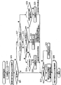
Figure 26 represents the internal structure according to transcriber of the present invention;
Figure 27 represents the size of writing rate Rx, Rc, Rd, graphics plane 8, coded data buffer 13, target buffer 15 and combined buffers 16;
Figure 28 means the sequential chart of the pipeline processes of being carried out by transcriber;
Figure 29 has been illustrated in the sequential chart in the pipeline processes of the situation that the decoding of ODS finishes before the removing of graphics plane;
Figure 30 means the flow chart of the load operation process of functional section;
Figure 31 represents a multiplexed example;
Figure 32 represents DS10 to be loaded into a kind of mode of coded data buffer 13;
Figure 33 represents DS1, the DS10 in normal reproduction, the loading of DS20;
Figure 34 is illustrated in the loading of the DS1 in normal reproduction, DS10 shown in Figure 33 and DS20;
Figure 35 represents the flow chart of the processing carried out by graphics controller 17;
Figure 36 represents the flow chart of the processing carried out by graphics controller 17;
Figure 37 represents the flow chart of the processing carried out by graphics controller 17;
Figure 38 is illustrated in the pipeline processes of the transcriber on the PTS basis of PDS;
Figure 39 is the schematic diagram of meaning of the END in the pipeline processes of statement transcriber;
Figure 40 represents according to the internal structure of the transcriber of the second embodiment;
Figure 41 schematically shows the operation of reading and writing the graphics plane that forms double buffering;
Figure 42 means according to the flow chart of the manufacturing process of the BD-ROM of the 3rd embodiment.
Implement best mode of the present invention
The first embodiment
Explained later is according to the first embodiment of recording medium of the present invention.
Fig. 1 represents the example of the use of recording medium.In the drawings, BD-ROM 100 is according to recording medium of the present invention.BD-ROM 100 is for providing cinematographic work data to the household audio and video system consisting of transcriber 200, TV 300 and remote controller 400.
Recording medium according to the present invention is that the improvement of the application layer (applicationlayer) by BD-ROM is manufactured.Fig. 2 represents the structure of BD-ROM.
In the figure, in the bottom of figure, show BD-ROM, and at the track showing above BD-ROM on BD-ROM.In fact this track is spiral-shaped on dish, but shown in figure is straight line.This track comprises ,Juan district, importing (lead-in) district (volume area) and leading-out zone.This Tu Zhongjuan district has physical layer, file system layer and application layer.At the top of figure, use bibliographic structure to show the application form of BD-ROM.As shown in the figure, BD-ROM has the catalogue BDMV under root, and BDMV catalogue comprise have extension name M2TS (XXX.M2TS) for store AVClip file, have extension name CLPI (XXX.CLPI) for store AVClip management information file and there is the file that is used to AVClip definition logic playlist (PL) of extension name MPLS (YYY.MPLS).By forming above-mentioned application form, can manufacture according to recording medium of the present invention.In the situation that having more than one file for every type, preferably under BDMV, provide three catalogues of called after STREAM, CLIPINF and PLAYLIST, to store the file with identical extension name in a catalogue.Specifically, wish that storage has the file of extension name MSTS in STREAM, storage has the file of extension name CLPI and in PLAYLIST, stores the file with extension name MPLS in CLIPINF.
AVClip (XXX.M2TS) in the above-mentioned application form of explained later.
AVClip (XXX.M2TS) is by the digital stream of the MPEG-TS form (TS is transport stream) that multiplex video flows, at least one audio stream and present graphical stream obtains.Video flowing represents the image of film, and audio stream represents the sound of film, and present graphical stream (presentation graphics stream) represents the captions of film.Fig. 3 is the diagram that schematically shows the structure of AVClip.
AVClip (XXX.M2TS) forms in such a way.By a plurality of frame of video (image pj1, pj2 and pj3) each video flowing forming and the audio stream consisting of a plurality of audio frames (top line of figure) be converted into a line PES packets of information (the second row of figure), is then converted into a line TS packets of information (the third line of figure).Present graphical stream (end row of figure) is converted into PES packets of information (row second from the bottom of figure), then converts TS packets of information (countdown line 3 of figure) to.Three row PS packets of information, by multiplexed, form AVClip (XXX.M2TS) thus.
In the drawings, only has a present graphical stream by multiplexed.But, in the situation that BD-ROM can be to multilingual compatibility, thus for the present graphical stream of every kind of language by multiplexed formation AVClip.With the AVClip that aforesaid way forms, be divided into more than one scope (extent), identical with common computer file, and be stored in each region in BD-ROM.
Then, explain present graphical stream.Fig. 4 A represents the structure of present graphical stream.Top line indicates to be multiplexed into the TS packets of information row of AVClip.From the second line display of top line number, form the PES packets of information row of graphical stream.PES packets of information row is that the payload that is had the payload in the TS packets of information of predetermined PID and connected this extraction by extraction forms.
Structure from the third line presentation graphic stream of top line number.This graphical stream shows that by called after the functional section of combined segment (PCS), window definition section (WDS), palette definition phase (PDS), object definition section (ODS) and the demonstration section of setting (END) END forms.In the middle of above-mentioned functions section, PCS is called as screen combination section, and WDS, PDS, ODS and END are called as definition phase.PES packets of information and each functional section are corresponding one by one, or a correspondence is a plurality of.In other words, a functional section, after being converted into a PES packets of information, or is recorded in BD-ROM after PES packets of information being divided into a plurality of fragments and converting to more than one.
Fig. 4 B represents the PES packets of information obtaining by translation function section.As shown in the figure, PES packets of information consists of packets of information header and payload, and payload is the main body of functional section.Packets of information header comprises DTS and PTS that should functional section.Below by the DTS and the PTS that are included in DTS in packets of information header and PTS and are called functional section.
Above-mentioned various functional section forms logical construction as shown in Figure 5.Fig. 5 represents the logical construction consisting of various functional sections.In the drawings, unit (epoch) when top line represents, middle line display shows setting (DS), end line display functional section.
In the middle of all a plurality of functional sections of formation graphical stream, each DS shown in middle row is the one group of functional section that forms the figure of a screen.Dotted line in figure represents that the functional section in end row belongs to the DS being indicated by this dotted line, and represents that a string functional section such as PCS, WDS, PDS, ODS and END forms a DS.This transcriber can produce by reading the functional section of formation DS the figure of a screen.
Time unit shown in top line represents the time cycle, and the time shaft storage management of reproducing along AVClip in unit in the time of is continuous in time.In the time of one, unit also represents to distribute to one group of data in same time cycle.Here alleged memory is the graphics plane that stores the figure of a screen, and stores the target buffer of decompression graph data.The continuity of storage management mean this time can there is not the flicker of graphics plane or target buffer in unit, and only carry out wiping and representing (all the elements that the flicker here represents to wipe the storage data in plane or buffer) of figure in the predetermined rectangular area on graphics plane.In the time of one, in unit, size and the position of rectangular area are fixed.As long as only carry out wiping and representing of figure in the predetermined rectangular area on graphics plane, just can guarantee the reproduced in synchronization between image and figure.In other words, this time unit be a unit in recovery time axle, and in this unit, guarantee that image and figure synchronously reproduce.When this region of wiping therein and represent figure is moved to diverse location, must on time shaft, define a point and move this region, and a period of time after this point becomes a new time unit.Interval in the time of two between unit can not guarantee reproduced in synchronization.
When watching actual film, in the time of one, unit shows the time cycle of captions in the identical rectangular region on screen.Fig. 6 represent captions position and time relation between unit.In this example shown in the drawings, illustrate five captions " Actually ... ", " I was hiding ", " myfeeling ", " I always " and " loved you " move according to the image in film.Specifically, captions " Actually ..., " I was hiding " and " my feeling " appear at the bottom of screen, and captions " I always " and " loved ybu " are presented at the top of screen.When watching screen, consider the appreciative value of film, the position of rectangular area is mobile so that captions shielded image not.The time cycle that captions appear at bottom unit 1 while being, unit 2 when next time cycle that captions appear at top is.Time unit 1 and 2 has zones of different separately to show therein captions.Time region in unit 1 be the window 1 that is positioned at bottom of screen, and time region in unit 2 be the window 2 that is positioned at the top of screen.Storage management is continuous in each time unit 1 and 2, thereby, in demonstration and the image synchronization of the captions of window 1 and 2.
Then, will introduce in detail and show setting (DS).
Unit when which capable functional section belongs in the middle of the dotted line hkl1 in Fig. 5 and hkl2 represent to be positioned at.Unit when a series of DS " Epoch Start " (time unit start), " collection point " are (AcquisionPoint) and " normal condition " (Normal Case) is formed in this of top row." EpochStart ", " Acquision Point " and " Normal Case " are each types of DS, and the order between " Acquision Point " and " Normal Case " all it doesn't matter, in them, any can first occur.
Epoch Start is the DS with the display effect of " newly show ", and it represents the beginning of unit when new.Therefore, Epoch Start comprises for the required all functions section of the new element of display screen.Epoch Start is arranged on the position of target of the skip operation (skip operation) as AVClip, as the chapters and sections in film.
Acquision Point is the DS with the display effect of " display update ", and it is identical with conduct at the Epoch of front DS Start for presenting the content of figure.The starting point of unit when AcquisionPoint is not arranged on, but the required all functions section of new component that comprises display screen.Therefore,, when Acquision Point is carried out to skip operation, ground display graphics can not break down.Thereby, utilize Acquision Point, can this time unit middle part form a screen.
Acquision Point is arranged on the position of the target that can be used as skip operation.The example of this position is the position of appointment can retrieve in the time of carrying out time.Time retrieval is in response to the operation of user's input time, thereby in correspondence, by the reproduction point of user-defined time, is started to reproduce.This time roughly stipulates, as differs 10 minutes or 10 seconds, correspondingly, reproduce the point starting be for example set to 10 minutes intervals or 10 second interval.By Acquision Point is provided, reproducing on the point that can start, can after time retrieval, reproduce smoothly.
Normal Case is the DS with the display effect of " display update ", and only comprises the element that is different from last screen composition.Specifically, but the captions in DSv are when the identical screen of captions in DSu shows by different way in DSv and Dsu, and DSv is arranged to only include PCS and makes DSv is Normal Case.Thus, needn't provide have with last DS in the ODS of content identical content of ODS, thereby can reduce the size of data in BD-ROM.On the other hand, because the DS as Normal Case only comprises difference, therefore use separately Normal Case can not form this screen.
The details of explained later definition phase (ODS, WDS and PDS).Object definition section (ODS) is the functional section that defines graphic object.First explain graphic object below.The attraction that is recorded in the AVClip in BD-ROM is its high-resolution the same with high definition TV, so the resolution of graphic object is arranged on 1920 * 1080 pixels.Due to the high-resolution of 1920 * 1080 pixels, can on screen, clearly illustrate the concrete character format of captions.About the color of captions, the bit length of the desired value of each pixel (the red Cr of aberration, aberration blue Cb, brightness Y and transparency T) is 8, therefore can from panchromatic (16777216 kinds of colors), select any 256 kinds of colors for these captions.The captions of being realized by graphic object present by text is set on transparent background.
The grammer of the ODS of definition graphic object is shown in Fig. 7 A.ODS is by representing that byte is the segment_type (section _ type) of ODS, the segment_length (section _ length) that represents the data length of ODS, represent uniquely to should time ODS in unit the object_id (target _ id) of graphic object, the object_version_number of the version of the ODS while representing this in unit (target _ version _ number), the object_data_fragment of the continuous sequence bit of last_insequence_flag (last _ non-sequence _ mark) and corresponding part or all graphic object of conduct.
Object_id for identify uniquely to should time ODS in unit graphic object.During this of graphical stream, unit comprises the more than one ODS with identical ID.The ODS with identical ID also has same widths and height, and is assigned with the public domain in target buffer.Read an ODS with identical ID in this public domain after, with the next ODS with identical ID, the ODS being read is rewritten.When carrying out the reproduction of video flowing, the ODS of target buffer is read in next ODS rewriting by use with identical ID, thereby upgrades the figure of this ODS.Only in the time of one, during unit, applied dimension constraint, that is, width and the height with the graphic object of identical ID should be identical, and the graphic object in unit can have different size when different.
Introduce last_sequence_flag (last _ sequence _ mark) and object_data_fragment (target _ data _ fragment) below.In some cases, due to the payload restriction of PES packets of information, can not in an ODS, store the decompression figure that forms captions.In these cases, figure splits into a series of continuous fragments, and a fragment is set to object_data_fragment.When a graphic object is when more than one fragment is stored, each fragment except last fragment has identical size.Last fragment is less than or equal to the size in front fragment.The ODS that carries these fragments appears in DS according to identical consecutive order, and last of the sequence wherein being represented by ODS has last_sequence_flag.Although the above-mentioned grammer of ODS is the hypothesis based on such, that is, the plurality of fragment from PES start stackingly, these fragments can be stacked into and make each PES contain blank parts.
Then, explain palette definition phase (PDS).PDS is for the palette of define color conversion use.Fig. 7 B represents the grammer of PDS.PDS by represent this section be the segment_type of PDS, represent the segment_length of the data length of PDS, uniquely indicate be included in the palette_id (palette _ id) of the palette in PDS, the palette_entry_id of the entry number (entry number) of the palette_version_number of the version of PDS while representing this in unit (palette _ version _ number) and regulation palette forms.Palette_entry_id (palette _ entry _ id) represents aberration red (Cr_value), aberration blue (Cb_value), brightness (Y_value) and transparency (T_value).
Next, introduce window definition section (WDS).
WDS is for defining the rectangular area on graphics plane.As mentioned above, when only wiping and manifesting in the region of certain on graphics plane, storage management is continuous.This region on graphics plane is defined by WDS and is called as " window ".Fig. 8 A shows the grammer of WDS.As shown in the figure, WDS is by representing that this section is the segment_type of WDS, the segment_length that represents the data length of WDS, indicate uniquely the window_id of this window on graphics plane, the window_horizontal_position of the horizontal address of the top left corner pixel of the window in compulsory figure plane, the window_vertical_position of the vertical address of the top left corner pixel of the window in compulsory figure plane, the window_height of the height of the window in the window_width of the width of the window in compulsory figure plane and compulsory figure plane forms.
Introduce the scope of the numerical value that window_horizontal_position, window_vertical_position, window_width and window_height can take below.In region for the coordinate system of these values on graphics plane, and the size bidimensional of this window ground is by representing the window_height of height and representing that the window_width of width represents.
The horizontal address of the top left corner pixel of this window in window_horizontal_position compulsory figure plane, and arrive in the scope of (window_width)-1 in 0.And, the vertical address of the top left corner pixel of this window in window_vertical_position compulsory figure plane, and arrive in the scope of (window_height)-1 in 0.
The width of this window in window_width compulsory figure plane.The width of regulation falls into 1 in the scope of (video_width)-(window_horizontal_position).In addition, the height of the window in window_height compulsory figure plane, and the height of this regulation 1 in the scope of (video_height)-(window_vertical_position).
Each time window on graphics plane in unit position and size by window_horizontal_position, window_vertical_position, window_width and window_height, defined.Thereby, can regulate position and the size of the window forming, make when watching film, the window in the time of in unit appears on the position of shielded image not.Thus, the observability of captions becomes higher.Due to for each time unit defined WDS, even image along with the time changes, also can be according to the position of image adjustment window.Result is, the quality of film remains equally high with situation about being attached at captions in the main body of film.
Then, explain the end that shows the section of setting (END).END provides the information of the transmission of DS.In data flow, End is inserted into immediately following after the last IDS in a DS, End is by representing that this section is the segment_type of END and representing that the segment_length of the data length of END forms.END does not comprise any other element that needs are further explained.
Then, introduction is illustrated as to segmentation (PCS) below.
PCS is for forming the interactive functional section showing.Fig. 8 B represents the grammer of PCS.As shown in the figure, PCS consists of segment_type, segment_length, composition_number, Composition_state, palette_update_flag, palette_id and window information 1-m.
Composition_number upgrades by the figure in the numeric representation DS in the scope of 0-15.If figure upgrades between the head and PCS of unit while being present in, when upgrading, each generation figure increases composition_number.
Composition_state represents wherein to contain type, Normal Case, Acquision Point or the Epoch Start of the DS of PCS.
Palette_update_flag represents that PCS describes the only display update to palette.Only to the display update of palette represent to only have palette from adjacent palette upgrade.If carry out the only display update to palette, palette_update_flag field is set to " 1 ".
Palette_id indicates the palette that will use in only to the display update of palette.
Window information 1-m represents how to control each window in the DS that comprises this PCS.Dotted line wd1 in Fig. 8 B is at length explaining the internal grammar of window information i.Window information i consists of object_id, window_id, object_cropped_flag, object_horizontal_position, object_vertical_position and cropping_rectangle information 1-n.
Object_id indicates the ODS in the window of corresponding window information i.
Window_id is indicated in the window that has distributed graphic object in PCS.Maximum two graphic objects can be distributed to a window.
Object_cropped_flag for target buffer the demonstration of cutting graphic object and non-display between switch.When object_cropped_flag is set to " 1 ", cutting graphic object is presented in target buffer, and if be set to " 0 ", display graphics target not.
The horizontal address of the top left corner pixel of the graphic object in object_horizontal_position compulsory figure plane.
The vertical address of the top left corner pixel of the graphic object in object_vertical_position compulsory figure plane.
Cropping_rectangle information 1-n is the element using while being set to " 1 " at object_cropped_flag.Dotted line wd2 is for representing the details for the internal grammar of cropping_rectangle information i.As shown in dotted line wd2, cropping_rectangle information i consists of four fields: object_cropping_horizontal_position, object_cropping_vertical_position, object_cropping_width and object_cropping_height.
Object_cropping_horizontal_position is defined in the horizontal address at the angle, the upper left corner of the cutting rectangle using during display graphics target in graphics plane.Cutting rectangle is for stipulating the crop box with cutting part graphic object, and the region in corresponding ETSI EN 300 743 standards.
Object_cropping_vertical_position is defined in the vertical address that manifests the angle, the upper left corner of the cutting rectangle using during graphic object in graphics plane.
Object_cropping_width stipulates the width of this cutting rectangle.
Object_cropping_height stipulates the height of this cutting rectangle.
Introduce in detail the object lesson of PCS below.In this embodiment, when image player, captions as shown in Figure 6 " Actually ... ", " I was hiding " and " my feelings. " write graphics plane by 3 times and little by little occur.Fig. 9 is for realizing the example of the explanation of this Subtitle Demonstration.Time unit in figure comprises DS1 (Epoch Start), DS2 (Normal Case) and DS3 (Normal Case).DS1 is containing being useful on WDS that regulation wherein shows the window of captions, for regulation lines " Actually ... I was hiding my feelings. " and a PCS.DS2 contains the 2nd PCS, and DS3 contains the 3rd PCS.
Figure 10-12 are illustrated in the WDS that contains in DS and the example of PCS.Figure 10 represents the example of the PCS in DS1.
In Figure 10, the window_horizontal_position of WDS and window_vertical_position are by the positional representation of the top left corner pixel of the window on LP1, graphics plane.Window_width and window_height represent respectively width and the height of this window.
In Figure 10, object_cropping_horizontal_position and object_cropping_vertical_position represent the reference point ST1 of a cutting rectangle in coordinate system, and the initial point of this coordinate system is the top left corner pixel of graphic object.Cutting rectangle is to have width from ST to object_cropping_width and the region (by the rectangle shown in bold box) of the height from ST to object_cropping_height.Cutting graphic object is positioned at the rectangle that dotted line frame cp1 represents, have the reference point in coordinate system, the initial point of coordinate system is arranged in object_horizontal_position and the object_vertical_position (top left corner pixel of graphic object) of graphics plane.Thus, by captions " Actually ... " write the window on graphics plane, then combine and be presented on screen with film image.
Figure 11 represents the example of the PCS in DS2.Do not explain the WDS in DS2, because the WDS in DS2 is identical with the WDS in DS1.The description of the cutting information in DS2 is different from the description of the cutting information shown in Figure 10.
In Figure 11, the object_cropping_horizontal_position in cutting information and object_cropping_vertical_position represent the top left corner pixel of the captions " I was hiding " in " Actually ... Iwas hiding my feelings. " in target buffer.The width of the rectangle that object_cropping_width and object_cropping_height represent to contain captions " I washiding " and height.Thus, captions " I was hiding " are written on graphics plane, then combine and are presented on screen with film image.
Figure 12 is illustrated in the example of the PCS in DS3.Because the WDS in DS3 is identical with the WDS in DS1, therefore do not explain the WDS in DS3.The description of the cutting information in DS3 is different from the description of the cutting information shown in Figure 10.
In Figure 12, the object_cropping_horizontal_position in cutting information and object_cropping_vertical_position represent the top left corner pixel of the captions " my feelings " in " Actually ... Iwas hiding my feelings. " in target buffer.The width of the rectangle that object_cropping_width and object_cropping_height represent to contain captions " myfeelings " and height.Thus, captions " my feelings " are written in the window of graphics plane, then combine and are presented on screen with film image.
As mentioned above, by describing DS1, DS2 and DS3, can realize the effect that shows captions on screen.Can also realize other effect, and introduce below for realizing the description protocol of other effect.
First, explain the description protocol for cutting/cutting out.Figure 13 is illustrated in the example representing along time shaft to the description of DS when cutting/cutting out.
In the drawings, the value that the x in window (x, y, u, v) and y represent respectively window_vertical_position and window_horizontal_position, and u and v represent respectively window_width and window_height.And in the drawings, cutting rectangle (a, b, c, d) a in and b represent respectively the value of object_cropping_vertical_position and object_cropping_horizontal_position, and c and d represent respectively the value of object_cropping_width and object_cropping_height.Show and arrange on some t11, the t12 and t13 on DS11, DS12 and the recovery time axle of DS13 in figure.
DS11 on a t11 comprise that wherein Composition_state is " Epoch Start " and object_cropped_flag be " 0 " PCS#0 (no_cropping_rectangle_visible), have the statement that the window of the width 700 * height 500 on (100,100) in graphics plane uses WDS# 0, PDS# 0, represent ODS# 0 and the END of captions " credit (Credits): ".
DS12 in a t12 comprises PCS# 1, its Composition_state is " NormalCase ", and the trimming operation of presentation graphic target (0,0) from target buffer starts, size is that 600 * 400 (cropping_rectangle#0 (0,0,600,400)), and by cutting graphic object be positioned at graphics plane (on Window#0 (0,0) coordinate) (0,0).
DS13 in a t13 comprises its PCS# 2, its Composition_state is " NormalCase ", and wherein object_cropped_flag is set to " 0 ", to wipe cutting graphic object (no_cropping_rectangle_visible).
Utilize above-mentioned demonstration setting, " Credits: " at t11, do not show, and occur at t12, and then do not show at t13, thereby realized incision/cut out effect.
Secondly, explain the description protocol for fade in/out effect.Figure 14 is illustrated in the example representing along time shaft of the explanation of DS while carrying out fade in/out.Show some t21, t22, t23 and the t24 on DS21, DS22, DS23 and the DS24 recovery time axle in figure is set.
DS21 on a t21 comprises PCS# 0, WDS# 0, PDS# 0, ODS# 0 and END, wherein the Composition_state of PCS# 0 is that " Epoch Start " the trimming operation that represents the graphic object in target buffer are from (0, 0) start and size is that 600 * 400 (cropping_rectangle#0 (0, 0, 600, 400)), and cutting graphic object is positioned to graphics plane (on Window#0 (0, 0) coordinate (0), 0), WDS# 0 has window is positioned to (100 of image plane, 100), size is the statement of width 700 * height 500, ODS# 0 represents captions " Fin ".
DS22 on a t22 comprises that its Composition_state is PCS# 1 and the PDS# 1 of " Normal Case ".PDS# 1 represents the value of Cr and the Cb identical with PDS# 0, but the brightness in the brightness ratio PDS# 0 being represented by PDS# 1 is high.
DS23 in a t23 comprises that its Composition_state is PCS# 2, PDS# 2 and the END of " Normal Case ".PDS# 2 represents the value of Cr and the Cb identical with PDS# 1, but the brightness in the brightness ratio PDS# 1 being represented by PDS# 2 is low.
DS24 on a t24 comprises that its Composition_state is that " Normal Case " and object_cropped_flag are " 0 " PCS and END (no_cropping_rectangle_visible).
Each DS regulation is different from the PDS at front DS, thereby in unit, the brightness with the graphic object that more than PCS manifests becomes high or low gradually in the time of one.Whereby, can realize the effect of fade in/out.
Below by the description protocol of explaining for rolling.Figure 15 is illustrated in the example of the explanation of the DS representing along time shaft while rolling.Show and arrange on some t31, t32, t33 and the t34 on DS31, DS32, DS33 and the DS34 recovery time axle in figure.
DS31 on a t31 comprise that its Composition_state is set to " EpochStart " and object_cropped_flag be " 0 " PCS#0 (no_cropping_rectangle_visible), WDS# 0, the PDS# 0 of statement of window with width 700 * height 500 that (100,100) in graphics plane are located be, ODS# 0 and the END of expression captions " Credits:Company ".
DS32 in a t32 comprises PCS# 1, its Composition_state is " NormalCase ", and the trimming operation of presentation graphic target is from (0 in target buffer, 0) starting size is that 600 * 400 (cropping_rectangle#0 (0,0,600,400)), and the coordinate (0,0) that cutting graphic object is positioned in graphics plane is located (on Window#0 (0,0)).600 * 400 the region starting from (0,0) in graphic object comprises a part " Credits " for the captions " Credits:Company " that are shown as two row, and therefore " Credits: " part appears on graphics plane.
DS33 in a t33 comprises PCS# 2, its Composition_state is " NormalCase ", and the trimming operation of presentation graphic target is from coordinate (0 in target buffer, 100) (cropping_rectangle#0 (0,100,600 for 600 * 400 sizes that start, 400)), and the coordinate (0,0) that the graphic object of cutting is positioned in graphics plane is located (onWindow#0 (0,0)).In target buffer from (0,100) region of 600 * 400 sizes that start comprises " Credits: " part and " Company " part of the captions shown in two row " Credits:Company ", and therefore " Credits: " and " Company " part appears in two row on graphics plane.
DS34 in a t34 comprises PCS# 3, its Composition_state is " NormalCase ", and the trimming operation of presentation graphic target is that (cropping_rectangle#0 (0 from target buffer, 200,600,400)) from (0,200) 600 * 400 of beginning size, and cutting graphic object is positioned to the coordinate (0,0) (on Window#0 (0,0)) in graphics plane.600 * 400 the region starting from (0,0) in graphic object is included in " Company " part of the captions shown in two row " Credits:Company ", and therefore " Company " part appears on graphics plane.These captions that can roll downwards in two row are described by above-mentioned PCS.
Finally, will explain for putting/mark the description protocol of effect under.The example of the explanation of the DS that Figure 16 represents to represent along time shaft when putting under/marking.Show and arrange on some t21, t22, t23 and the t24 on DS21, DS22, DS23 and the DS24 recovery time axle in figure.
DS51 on a t51 comprises that its Composition_state is that " Epoch Start " and object_cropped_flag are " 0 " PCS#0 (no_cropping_rectangle_visible), have ODS# 0 and END to WDS# 0, the PDS# 0 of the statement of the window of the width of locating in (100,100) 700 in graphics plane * height 500, expression captions " Fin ".
DS52 on a t52 comprises PCS# 1, its Composition_state is that the trimming operation of " NormalCase " and presentation graphic target is from target buffer (0,0) (cropping_rectangle#0 (0 for the 600 * 400SIZE starting, 0,600,400) coordinate (0), and in graphics plane, 0) upper location cutting graphic object (on Window#0 (0,0)).The region of 600 * 400 sizes that start from (0,0) in target buffer comprises captions " Fin ", therefore on graphics plane, occurs captions " Fin ".
DS53 in a t53 comprises PCS# 2, its Composition_state is " NormalCase ", and the trimming operation of presentation graphic target will be from (200 in target buffer, 0) (cropping_rectangle#0 (200,0,400 for the 400 * 400SIZE starting, 400)), and the coordinate (200,0) that the graphic object of cutting is positioned in graphics plane is located (onWindow#0 (200,0)).Thus, with the region that the coordinate (200,0) in window and (400,400) represent, become viewing area, and the region being represented by coordinate (0,0) and (199,400) becomes non-display area.
DS54 on a t54 comprises PCS# 3, its Composition_state is " NormalCase ", and the trimming operation of presentation graphic target is from (400 in target buffer, 0) (cropping_rectangle#00 (400,0,200 for the 200 * 400SIZE starting, 400)), and the graphic object of cutting is positioned on the coordinate (400,0) in graphics plane (on Window#0 (400,0)).Thus, with the region that the coordinate (0,0) in window and (399,400) represent, become non-display area.
Thus, along with non-display area becomes large, viewing area diminishes, and has therefore realized and has put/mark effect under.
As mentioned above, use corresponding language (script) can realize various effects, as cut/cut out, fade in/out, put under/mark and roll, therefore can do various layouts presents captions.
As follows in order to realize the constraint of above-mentioned effect.In order to realize rolling effect, the operation that need to window be removed and be repainted.Take Figure 15 as example, must carry out " window removing ", thereby at t32, from graphics plane, wipe graphic object " Credits: ", then carry out " window repaints ", thus the interim between t32 and t33 the lower part by " Credits: " and the upper part of " Company " write on graphics plane.Supposing that this interval is identical with the interval of frame of video, is important for the transfer rate between the desirable target buffer of rolling effect and graphics plane.
Here, introducing can be great constraint about window.Rc is the transfer rate between target buffer and graphics plane.Here the worst situation is to carry out with speed Rc that window is removed and window repaints.In this case, need to carry out that window is removed and each in repainting of window with half the speed (Rc/2) of Rc.
For window being removed and window repaints and video frame synchronization, need satisfied following equation,

If being 29.97, Rc, frame speed represented by following relational expression,
Rc=window size * 2 * 29.97
When showing captions, window size accounts at least 25% to 33% of graphics plane.Pixel total amount in graphics plane is 1920 * 1080.The index bit length of supposing every pixel is 8, and the total capacity of graphics plane is 2 megabits
.
Suppose window size be graphics plane total capacity 1/4, window size becomes 500K bit (=2M bit/4).By this is worth to generation in above-mentioned relation formula, calculating Rc is 256Mbps (=500K bit * 2 * 29.97).If for the speed that window is removed and window repaints can be frame speed half or 1/4th, even if Rc is identical, also can make the size of window become twice or four times.
By keeping this window size, be 25% to 33% of graphics plane, and show captions with the transfer rate of 256Mbps, no matter will realize the display effect of any kind, can keep the simultaneous display between figure and film image.
Then, introduce position, size and the area of window.As mentioned above, the position of window and area are constant in unit in the time of one.The position of window and size are set to identical in the time of one in unit, because if position and size change the target write address that must change graphics plane, and change the caused operation in address by the transfer rate reducing from target buffer to graphics plane.
The limited amount system of the graphic object of each window.Providing this to count quantitative limitation is the operation that transmits decoding graphic object in order to reduce.The operation is here to produce when the address at edge of graphic object is set, and the quantity at edge is more, and the operation of generation is more.
Figure 17 represents the example of mutually contrasting, and in an example, a window has four graphic objects, and in another example, a window has two graphic objects.The quantity at edge with the example of four graphic objects is the twices of amount of edge with the example of two graphic objects.
In the hard-core situation of quantity of graphic object, do not know can produce how many operations when transmitting figure, therefore for the load transmitting, sharply increase and reduce.On the other hand, when the maximum quantity of the graphic object in window is two, considering has at most 4 operating costs that transfer rate is set.Thereby, the amount of minimum transfer rate is more easily set.
Then, introduce the time shaft how DS with PCS and ODS is assigned to AVClip.Shi Yuan is a time cycle, and wherein storage management is continuous along recovery time axle.Due to time unit by more than one DS, formed, the recovery time axle that how DS is assigned to AVClip is very important.The recovery time axle of AVClip is for stipulating the time shaft of the decoding of every picture data and the timing of reproduction, and described view data forms the video flowing that is multiplexed as AVClip.Between decoding on recovery time axle and reproduction are fixed, use the accuracy representing of 90KHz.Be attached to the timing that PCS in DS and the DTS on ODS and PTS are illustrated in Synchronization Control on recovery time axle.By showing to arrange to be assigned on recovery time axle, mean and use the DTS and the PTS that are attached on PCS and ODS to carry out Synchronization Control.
First, by introducing, how to use the DTS and the PTS that are fixed on ODS to carry out Synchronization Control below.
With the precision of 90KHz, the moment when decoding that DTS is illustrated in ODS starts, the moment that PTS is illustrated in decoding while finishing.
The decoding of ODS does not complete immediately, but has regular hour length.In response to the request of starting point and the end point of the duration that represents to decode with will be clear that, the moment that the DTS of ODS and PTS are illustrated respectively in decoding when starting and finishing.
The value representation deadline of PTS, therefore must make the decoding of ODS complete before the time being represented by PTS, and the graphic object decompressing is written to the target buffer on transcriber.
The decode start time of any ODSj in DSn is represented by DTS (DSn[ODS]) with the precision of 90KHz.The maximum length of decoding duration is added to DTS (DSn[ODS]) is the decoding of the ODSj time while finishing.
When the size of ODSj is " SIZE (DSn[ODS]) " and the decoding speed of ODS while being " Rd ", that with stopwatch, shows is expressed as " SIZE (DSn[ODS]) //Rd " for the required maximum time of decoding.Symbol " // " represents the operator of carrying out division and the position after tenths being rounded up.
By maximum period of time being converted to the numeral of the accuracy representing of 90KHz and to be added to the DTS of ODSj upper, the time (90KHz) while finishing with regard to having calculated the decoding being represented by PTS.
The PTS of ODSj in DSn represents in order to lower relational expression,
PTS(DSn[ODSj])=DTS(DSn[ODSj])+90000×(SIZE(DSn[ODSj])//Rd)
In addition, must make two continuous ODS, the relation between ODSj and ODSj+1 meets following relational expression,
PTS(DSn[ODSj)≤DTS(DSn[ODSj+1])
Next explain the setting of DTS and the PTS of PCS.
Before the decode start time of a ODS (ODS1) that must be in DSn and the PDS (PDS1) in DSn become time when effective (PTS (DSn[PDS1]) and before, PCS be loaded into the target buffer on transcriber.Thereby, DTS must be arranged to meet following relational expression,
DTS(DSn[PCS])≤DTS(DSn[ODS1])
DTS(DSn[PCS])≤PTS(DSn[PDS1])
In addition, the PTS of the PCS in DSn represents in order to lower relational expression,
PTS(DSn[PCS])≥DTS(DSn[PCS])+decodeduration(DSn)
" decodeduration (DSn) " represents decoding duration for upgrading all graphic objects of PCS.Decoding is not fixed value the duration, but also not with transcriber be installed to device on transcriber or the state of software changes.When being DSn.PCSn.OBJ[j for forming the target of DSn.PCSn screen] time, decodeduration (DSn) is subject to (i) and removes required time of window, (ii) for the decoding duration of the DSn.PCSn.OBJ that decodes with (iii) for writing the DSn.PCSn.OBJ impact of required time.When Rd and Rc are set, decode_duration (DSn) is always identical.Therefore, by calculating the length of these duration of carrying out, calculate PTS.
The calculating of decode_duration is for carrying out on basis in the program shown in Figure 18.Figure 19,20A and 20B are the flow charts that schematically shows the algorithm of this program.Introduce with reference to the accompanying drawings the calculating about decode_duration.In the flow chart shown in Figure 19, first, call PLANEINITIALZE function (the step S1 in Figure 19).PLANEINITIALZE function makes the graphics plane initialization function of required time cycle for calling to calculate, for reproducing DS.In step S1 in Figure 19, operation parameter DSn, DSn.PCS.OBJ[0] and decode_duration call this function.
Below with reference to Figure 20 A, introduce PLANEINITIALZE function.In the figure, initialize_duration represents the variable of the return value of PLANEINITIALZE function.
Step S2 in Figure 20 is if statement, for whether representing Epoch Start and handover operation according to the page_state in the PCS of DSn.If page_state represents Epoch Start (DSn.PCS.page_state==epoch_start, the step S2=in Figure 18 is), remove the required time cycle of graphics plane to be set to initialize_duration (step S3).
Transfer rate Rc between target buffer and graphics plane is as above 256,000,000, and the overall size of graphics plane is while being set to video_width*video_height, and removing the required time cycle is " video_width*video_height//256000000 ".When being multiplied by 90.000Hz and representing with the time precision with PTS, removing the required time cycle of graphics plane is " 90000 * video_width*video_height//256000000 ".This time cycle is added on initialize_duration.
If page_state does not represent Epoch Start (step S2=is not), for all windows, the required time cycle of window [i] that removing is defined by WDS is added to initialize_duration upper (step S4).Transfer rate Rc between target buffer and graphics plane is as mentioned above 256,000,000 and the overall size that belongs to the window [i] of WDS be ∑ SIZE (WDS.WIN[i] time, remove the required time cycle and be " ∑ SIZE (WDS.WIN[i] // 256000000 ".While representing when being multiplied by 90.000Hz so that with the time precision of PTS, remove the required time cycle of window that belongs to WDS and be " 90000 * ∑ SIZE (WDS.WIN[i] // 256000000 ".It is upper that this time cycle is added to initialize_duration, and result is that initialize_duration is returned.PLANEINITIALZE function above.
Step S5 in Figure 19 is for being 2 or 1 to carry out handover operation according to the quantity of the graphic object of DSn, (in Figure 18, if (DSn.PCS.num_of_object==2, if (DSn.PCS.num_of_object==1), if with this quantity be 1 (step S5), be added to decode_duration (step S6) for stand-by period of the graphic object of decoding.The calculating of stand-by period be by call WAIT function (Figure 18, decode_duration+=WAIT (DSn, DS.PCS.OBJ[0], decode_duration) carry out.This function is used and is set to DSn, DSn.PCS.OBJ[0], the parameter such as decode_duration calls, and return value is wait_duration.
Figure 20 B means the flow chart of the operation of WAIT function.
In this flow chart, the decode_duration of caller (invoker) is set to current_duration.Object_definition_ready_time is the variable of PTS that is set to the graphic object of DS.
Current_time is the variable that is set to the DTS of the PCS in DSn and the total value of current_duration.When object_definition_ready_time is greater than current_time, (step S7 is yes, (if current_time < object_definition_ready_time)), wait_duration as return value is set to the difference (step S8, wait_duration+=object_definition_ready_time-current_time) between object_definition_ready_time and current_time.The return value that decode_duration is set to WAIT function is added to for repainting the time cycle of upper gained of required time cycle of this window, (90000* (SIZE (DSn.WDS.WIN[0])) // 256000000).
Explanation is above that the quantity about graphic object is 1 situation.In step S5 in Fig. 5, the quantity that judges whether graphic object is 2.If the quantity of graphic object is to be greater than 2 (in Figure 18 in DSn, ifDSn.PCS.num_of_object==2), use the OBJ[0 in PCS] as parameter, call WAIT function, and return value is added to decode_duration upper (step S10).
In step S11 subsequently, judge whether the OBJ[0 of DSn] under the affiliated window of window and graphic object [1] identical (if (DSn.OBJ[0]) .window_id==DSn.PCS.OBJ[1] .window_id).If this window is identical, use OBJ[1] as parameter, call WAIT function, and return value wait_duration is added to decode_duration upper (step S12), and will repaint OBJ[1] under required time of window (90000* (SIZE (DSn.WDS.OBJ[0] .window_id)) // 256000000) be added to decode_duration upper (step S13).
If judge that these windows are different (step S11, " difference "), will repaint OBJ[0] under required time of window (90000* (SIZE (DSn.WDS.OBJ[0] .window_id)) // 256000000) be added to decode_duration upper (step S15), use OBJ[1] as parameter, call WAIT function, return value wait_duration is added to decode_duration upper (step S16), and will repaint OBJ[1] under required time of window (90000* (SIZE (DSn.WDS.OBJ[0] .window_id)) // 256000000) be added to decode_duration upper (step S17).
By above-mentioned algorithm, calculate decode_duration.Introduce the concrete mode of the PTS that OCS is set below.
Figure 21 A represents the situation that comprises an ODS in a window.Figure 21 B and 21C are sequential charts, according to the order of the time showing in Figure 18, show each value.End row in each figure " ODS decoding " and middle row " graphics plane access " are illustrated in two operations simultaneously carrying out while reproducing.Above-mentioned algorithm is to describe in the situation that these two operations of hypothesis are carried out side by side.
Graphics plane access comprises removing cycle (1) and write cycle time (3).The removing cycle (1) represents to remove the required time cycle (90000 * (size // 256000000 of graphics plane)) of whole graphics plane, or removes the required time cycle (∑ (90000 * (size // 256000000 of window [i])) of all windows on graphics plane.
Write cycle time (3) represents to show required time cycle (90000 * (size // 256000000 of window [i]) of whole window.
In addition, the decoding cycle (2) represents the DTS of ODS and the time cycle between PTS.
The length of removing cycle (1), decoding cycle (2) and write cycle time (3) can change according to the size of the scope that will remove, the ODS that will decode and the size that will write the graphic object of graphics plane.For convenience's sake, the starting point in the decoding cycle (2) in figure is identical with the starting point in removing cycle (1).
Figure 21 B represents that very long and decode_duration of decoding cycle (2) equals the situation of the summation of decoding cycle (2) and write cycle time (3).
Figure 21 C represents that the removing cycle (1) is very long, and decode_duration equals the situation of the summation of removing cycle (1) and write cycle time (3).
Figure 22 A-22C is illustrated in the situation that a window comprises two ODS.The decoding cycle (2) in Figure 22 B and 22C represents for decoding two cycles total time that figure is required.Equally, write cycle time (3) represents for two figures are write to required cycle total time of graphics plane.
Even if the quantity of ODS is 2, also can utilize the mode identical with the situation of Figure 21 to calculate decode_duration.When the decoding cycle for two ODS that decode, (3) were very long, decode_duration equals the summation of decoding cycle (2) and write cycle time (3), as shown in Figure 22 B.
When the removing cycle, (1) was very long, decode_duration equals the summation of removing cycle (1) and write cycle time (3).
Figure 23 A represents that each window of two windows comprises the situation of an ODS.Identical with former situation, when the removing cycle (1) is longer than the decoding cycle (3) for two ODS that decode, decode_duration equals the summation in removing cycle (1) and decoding cycle (2).Yet, when (1) the ratio decoder cycle in removing cycle (3) in short-term, can write in decoding cycle (2) first window before finishing.Thereby decode_duration is not equal to the summation of removing cycle (1) and write cycle time (3), or any one in the summation of decoding cycle (2) and write cycle time (3).
When for the required time cycle of ODS of decoding being write cycle time (31) and being write cycle time (32) for the 2nd required time cycle of ODS of decoding, Figure 23 B has represented the situation that the decoding cycle (2) is longer than the summation of removing cycle (1) and write cycle time (31).In this case, decode_duration equals the summation of decoding cycle (2) and write cycle time (32).
Figure 23 C represents the long situation of summation ratio decoder cycle (2) of removing cycle (1) and write cycle time (3).In this case, decode_duration equals the summation of removing cycle (1), write cycle time (31) and write cycle time (32).
From the pattern of transcriber, learn in advance the size of graphics plane.And the size of window and the size of ODS and quantity also can be learnt when creating.Thereby, can find that decode_duration equals the combination of which time cycle: removing cycle (1) and write cycle time (3), decoding cycle (2) and write cycle time (3), decoding cycle (2) and write cycle time (32), or removing cycle (1), write cycle time (3) and write cycle time (32).
By calculating the PTS that ODS is set on the basis of above-mentioned decode_duration, can be with high accuracy and view data display graphics synchronously.The region that repaints this window by definition window and restriction makes this high-precision simultaneous display become possibility.Therefore, the concept of window is introduced in authoring environment (authoring environment) and is significant.
The setting of DTS and the PTS of WDS in DSn will be introduced below.The DTS of WDS can be arranged to meet following relational expression,
DTS(DSn[WDS])≥DTS(DSn[PCS])
On the other hand, the OTS of the WDS in DSn represents to start to write the deadline of graphics plane.Because the window of writing on graphics plane is just enough, the time that starts to write graphics plane is by from deducting the time span that the PTS by PCS represents and determine for writing the required time cycle of WDS.When the overall size of WDS is ∑ SIZE (WDS.WIN[i]), for removing and repaint the required time cycle, be " ∑ SIZE (WDS.WIN[i]) // 256000000 ".When the time precision with 90.000KHz represents, this time is " 90000 * ∑ SIZE (WDS.WIN[i]) // 256000000 ".
Correspondingly, can calculate by following relational expression the PTS of WDS,
PTS(DSn[WDS])=PTS(DSn[PCS])-90000×∑SIZE(WDS.WIN[i])//256000000
The PTS representing in WDS is deadline, and can earlier start to write graphics plane than PTS.In other words, as shown in figure 23, once the ODS that will manifest in a window is decoded, the write operation of the graphic object obtaining by decoding can start at this moment.
As mentioned above, can use any time point being added on the DTS of WDS and recovery time axle that PTS distributes to this window AVClip.
The example that shows the setting of DTS in arranging and PTS below with reference to the object lesson introduction shown in Figure 24-25 on the basis of these settings.This example is about showing captions and carry out more news for each that shows two captions " what is blu-ray " and " blu-rayis everywhere " by writing graphics plane for four times.Figure 24 represents to upgrade over time in this embodiment.Until some t1, demonstration " what " until t2 shows " what is ", then shows " what is blu-ray " at t3 after t1.After there is the whole sentence of the first captions, at t4, show the second captions " blu-ray is everywhere ".
Figure 25 A represents to show setting in order to carry out described four of above-mentioned renewal.DS1 comprises PCS1.2 for being controlled at the renewal of t1, for the ODS1 of painted PDS1, corresponding captions " whatis blu-ray " with as the END of the end code of DS1.
DS2 comprises for being controlled at PCS1.2 and the END of the renewal of t2.DS3 comprises for being controlled at PCS1.3 and the END of the renewal of G.DS4 comprises ODS2 and the END of PCS2, the PDS2 for color conversion for being controlled at the renewal of t2, corresponding captions " blu-ray is everywhere ".
Referring to the sequential chart in Figure 25 B, explain the DTS of each functional section and the setting of PTS of four demonstrations in arranging.
Recovery time axle in sequential chart is identical with the time shaft in Figure 24.In the sequential chart of Figure 25 A, PTS (PCS1.1), PTS (PCS1.2), PTS (PCS1.3) and PTS (PCS2) are separately positioned on for the demonstration point t1 of demonstration " what ", for the demonstration point t2 of demonstration " what is ", for the demonstration point t3 of demonstration " what is blu-ray " with for showing the demonstration point t4 of " blu-rayis everywhere ".Each PTS is according to above-mentioned such setting, because must control on the demonstration point of each captions, for example, in the cutting described in each PCS.
PTS (ODS1) and PTS (ODS2) are arranged to represent by deducting from the point being represented by PTS (PCS1.1) and PTS (PCS2) respectively the point that decode_duration calculates respectively, this is because PTS (PCS) must be arranged to meet following formula
PTS(DSn[PCS])≥DTS(DSn[PCS])+decodeduration(DSn)
In Figure 25 B, PTS (ODS2) is arranged to the some t5 that represents that some t4 occurs before, and PTS (ODS1) is arranged to the some t0 occurring before being illustrated in a t1.
DTS (ODS1) and DTS (ODS2) are arranged to represent by deducting from the point being represented by PTS (ODS1) and PTS (ODS2) respectively the point that decode_duration calculates, this is because DTS (ODS) must be arranged to meet following equation
PTS(DS[ODSj])=DTS(DSn[ODSj])+90000×(SIZE(DSn[ODSj])//Rd)
In Figure 25 B, PTS (ODS2) is arranged to the some t5 occurring before being illustrated in a t0, and PTS (ODS1) is arranged to the point occurring before being illustrated in a t0.Here meet the relation being represented by DTS (ODS2)=PTS (ODS1).
The PTS that ODS is set after the PTS by the previous ODS that formerly shows immediately, transcriber carries out such operation, wherein this ODS is read in memory to rewrite previous ODS, therefore can carry out reproduction processes by small size memory.By realizing this reproduction processes, the selection that can be used for the memory-size of transcriber becomes wider.
The DTS of PCS1.1 is set to DTS (PCS1.1)=DTS (ODS1), because the value of the DTS of PCS1.1 can be by any point before the point of DTS (ODS1) expression.
The PTS of the PTS of ODS1, the DTS of ODS2 and PCS1.2, PCS1.3 and PCS2 is arranged on a little 0, to meet the relation being represented by following relational expression,
PTS(ODS1)=DTS(ODS2)=PTS(PCS1.2)
=PTS(PCS?1.3)=PTS(PCS2)
This is because can be any point before the point being represented by PTS (PCS 1.3) for the value of the DTS of PCS1.2 and PCS1.3, and the DTS of PCS2 can be any point before the point being represented by DTS (PCS2).
As mentioned above, by read more than one PCS simultaneously, after the renewal having completed at front PCS, just can carry out immediately the renewal of a rear PCS.
The DTS of the DTS of PCS and PTS and ODS and PTS meet the relation being represented by above-mentioned formula.Thereby, can make these values be set to DTS (ODS2)=PTS (ODS1) or PTS (ODS1)=DTS (ODS2)=PTS (PCS1.2)=PTS (PCS1.3)=DTS (PCS2).By this set to timestamp, the load in the time of can regulating decoding increases or needs the length in the cycle of more buffers.This adjusting has expanded the possibility in the control of reproduction period, and is conducive to create or manufacture the people of transcriber.
The data structure of above-mentioned demonstration setting (PCS, WDS, PDS, ODS) is the example with the taxonomic structure of describing in programming language.The author who creates can be by carrying out interpretive classification structure and obtain this data structure on BD-ROM according to the grammer providing with Blu-ray dish prerecorded form.
Then, introduce according to the concrete instance of transcriber of the present invention below.Figure 26 represents the internal structure according to transcriber of the present invention.Transcriber according to the present invention is on internal structure basis shown in the figure can industrial manufacture.According to transcriber of the present invention, mainly by following three parts, formed: system LSI, driving element and microcomputer system, and can be by these three parts being installed to this transcriber of industrial manufacture on the housing of this device and substrate.System SI is integrated circuit, wherein integrated for carrying out each processing unit of the function of this transcriber.The transcriber of manufacturing in the manner described above comprises BD driving 1, read buffers 2, pid filter 3, transmits buffer 4a-4c, peripheral circuit 4d, Video Decoder 5, video plane 6, audio decoder 7, graphics plane 8, CLUT unit 9, adder 10, graphic decoder 12, coded data buffer 13, peripheral circuit 13a, stream graphics processor 14, target buffer 15, combined buffers 16 and graphics controller 17.
BD drives 1 loading of carrying out BD-ROM/read/eject and access BD-ROM.
Read buffers 2 is for the order according to first in first out, to store the FIFO memory of the TS packets of information reading from BD-ROM.
3 pairs of more than one TS packets of information of exporting from read buffers 2 of pid filter are carried out filtering.The filtration of being undertaken by PID3 is only the TS packets of information with desired PID to be write and transmitted buffer 4a-4c.For the filtering of being undertaken by pid filter 3, do not need buffering, thereby, do not having the in the situation that of delay the TS packets of information that is input to pid filter 3 to be write on transmission buffer 4a-4c.
Transmitting buffer 4a-4c is to store from the TS packets of information of pid filter 3 outputs for the order according to first in first out.From transmitting the speed of buffer 4a-4c output TS packets of information, be speed Rx.
5 pairs of more than one TS packets of information of exporting from pid filter 3 of Video Decoder are decoded as decompressing image, and write video plane 6.
7 pairs of TS packets of information of exporting from pid filter 3 of audio decoder are decoded and export decompression audio data.
Peripheral circuit 13a is the wired logic circuitry of the transmission between transmission, coded data buffer 13 and the combined buffers 16 realizing between coded data buffer 13 and stream graphics processor 14.In transfer operation, when in current time, be the DTS by ODS represent time time, ODS is sent to stream graphics processor 14 from coded data buffer 13.Current time be the DTS by PCS and PDS represent time time, PCS and PDS are sent to combined buffers 16.
Combined buffers 16 is memories that PCS and PDS are wherein set.
Then, introduce the recommendation of the buffer size of transfer rate and formation pid filter 3, transmission buffer 4a-4c, graphics plane 8, CULT unit 9, coded data buffer 13 and graphics controller 17 below.Figure 27 represents the size of writing rate Rx, Rc and Rd, graphics plane 8, coded data buffer 13, target buffer 15 and combined buffers 16.
Transfer rate Rc between target buffer 15 and graphics plane 8 is the maximum speed in the transcriber of the present embodiment, and is calculated as 256Mbps (=500Kbytes * 29.97 * 2) by window size and frame speed.
Different from Rc, the transfer rate Rd between stream graphics processor 14 and target buffer 15 (pixel decoding speed) needn't be updated in the circulation of each frame of video, and Rd is the 1/2 or 1/4 just enough of Rc.Thereby Rd is 128Mbps or 64Mbps.
The transmission buffer leakage rate Rx transmitting between buffer 4a-4c and coded data buffer 13 is the transfer rate of the ODS under compressive state.Thereby the transfer rate Rd that is multiplied by compression ratio is enough to be used in transmitting buffering leakage rate Rx.The compression ratio of supposing ODS is that 25%, 16Mbps (=64Mbps * 25%) is just enough.
Transfer rate shown in figure and buffer size are minimum sandardses, and also can be set to fair speed and large-size.
In the transcriber of above-mentioned formation, the decode operation in each element execution pipeline structure.
Figure 28 means the sequential chart of the pipeline processes of being undertaken by transcriber.The 5th row in figure is the demonstration setting in BD-ROM, the read cycle of the 4th line display from PCS, WDS, PDS and ODS to coded data buffer 13.The decoding cycle of each ODS that the 3rd line display is carried out by stream graphics processor 14.The operation that the 1st line display graphics controller 17 is carried out.
The DTS (decode start time) that is additional to ODS1 and ODS2 distinguishes t31 and the t32 in presentation graphs.Because decode start time is arranged by DTS, so each ODS need to read into coded data buffer 13.Thereby, before ODS1 being decoded to the decoding cycle dp1 of coded data buffer 13, complete reading of ODS1.And, before ODS2 being decoded to the decoding cycle dp2 of coded data buffer 13, complete reading of ODS2.
On the other hand, the PTS (decoding end time) that is additional to ODS1 and ODS2 distinguishes t32 and t33 in presentation graphs.The decoding of the ODS1 carrying out by stream graphics processor 14 is to complete before t32, and completes before time of representing at t33 of the decoding of ODS2.As mentioned above, before the time representing at the DTS of ODS, stream graphics processor 14 just ODS is read coded data buffer 13, and before the time representing at the PTS of ODS, to reading the ODS of coded data buffer 13, decode, and the ODS of decoding is write to target buffer 15.
The cycle cd1 presentation graphic controller 17 of the 1st row is removed the required cycle of graphics plane in the drawings.And cycle td1 represents the graphic object obtaining on target buffer to write the required cycle of graphics plane 8.The PTS of WDS represents the deadline that starts to write, and the PTS of PCS represents end time and the timing for showing write.The time representing at the PTS by PCS, on graphics plane 8, obtain the decompression figure that forms interactive screen.
In graphic decoder 12, stream graphics processor 14 is decoded continuously, and graphics controller 17 carries out the removing of graphics plane 8 simultaneously.By above-mentioned pipeline processes, can carry out the instant playback of figure.
In Figure 28, explained the situation that the removing of graphics plane before the decoding that completes ODS finishes.Figure 29 has been illustrated in the sequential chart in the pipeline processes in the situation that ODS decoding finishes before the removing of graphics plane.In this case, can not when the decoding that completes ODS, write graphics plane.When completing the removing of graphics plane, just the figure obtaining by decoding can be write to graphics plane.
Then, introduce and how to move control unit 20 and graphic decoder 12 below.Control unit 20 is to move by writing one section of program and making general CPU carry out this program, the operation shown in this program execution 30.The operation of carrying out by control unit 20 below with reference to Figure 30 introduction.
Figure 30 means the flow chart of processing of the loading operation of functional section.In this flow chart, section K is variable, each section (PCS, WDS, PDS and ODS) of reading while being illustrated in reproduction of AV Clip.Ignore-tag is the mark of determining whether section K is left in the basket or loads.This flow chart has loop structure, and wherein first ignore-tag is initialized to 0, then to each section of K repeated execution of steps S21-S24 and step S27-S31 (step S25 and step S26).
Whether step S21 is to be PCS for the section of judgement K, if section K is PCS, carries out the judgement in step S27 and step S28.
Step S22 is for judging whether ignore-tag is 0.If ignore-tag is 0, operation moves to step S23, if ignore-tag is 1, operation moves to step S24.If ignore-tag is 0 (being yes in step S22), in step S23, section K is loaded in coded data buffer 13.
If whether ignore-tag is 1 (in step S22), the section of ignoring K in step S24.Thus, due to step S22 whether (step S24), ignore all the other all functions sections that belong to DS.
As mentioned above, whether section K ignores or loads by ignore-tag and determine.Step S27-S31, S34 and S35 are for the step of ignore-tag is set.
In step S27, whether the segment_type of judgement section K is Acquision Point.If section K is Acquision Point, operation moves to step S28, if section K is Epoch Start or Normal Case, operation moves to step S31.
In step S28, judge whether to be present in (coded data buffer 13, stream graphics processor 14, target buffer 15 and combined buffers 16) in any buffer in graphic decoder 12 at front DS.During being judged as YES in step S27, carry out the judgement in step S28.At front DS, be not present in the situation that situation in graphic decoder 12 represents to carry out skip operation.In this case, from the DS as Acquision Point, start to show, so whether transition of operation is to step S30 (in step S28).In step S30, ignore-tag is set to 0, and operation moves to step S22.
Situation about being present in graphic decoder 12 at front DS refers to the situation of carrying out normal reproduction.In this case, operation moves to step S29 (being yes in step S28).In step S29, ignore-tag is set to 1, and operation moves to step S22.
In step S31, judge whether the segment_type of PCS is Normal Case.If PCS is Normal Case, operation moves to step S34, if PCS is EpochStart, in step S30, ignore-tag is set to 0.
In step S34, with the same in step S28, whether judgement is present in any buffer in graphic decoder 12 at front DS.If existed at front DS, ignore-tag is set to 0 (step S30).If do not existed at front DS, can not obtain enough functional sections and form interactive screen, ignore-tag is set to 1 (step S35).
By with aforesaid way, ignore-tag being set, when not being present in graphic decoder 12 at front DS, ignore the functional section that forms Normal Case.
With DS carried out to multiplexed situation introduce as an example the mode reading of how to carry out DS as shown in figure 31.In the example of Figure 31, three DS and moving image are multiplexed.The segment_type of DS1 is Epoch Start, and the segment_type of DS10 is Acquision Point, and the segment_type of DS20 is Normal Case.
Suppose three DS and moving image carrying out in multiplexed AVClip, carry out the view data pt10 skip operation represented by arrow am1, and DS10 is close to jump target, so DS10 is the DS representing in the flow chart in Figure 30.Although judge that in step S27 segment_type is Acquision Point, but because be not present in coded data buffer 13 and ignore-tag is set to 0 at front DS, and DS10 is loaded into the coded data buffer 13 of transcriber, as shown in the arrow md1 in Figure 32.On the other hand, in the situation that jump target in DS10 (shown in the arrow am2 in Figure 31) afterwards, DS20 will be left in the basket, and show setting, and because be not present in (the arrow md2 in Figure 32) in coded data buffer 13 at front DS because DS20 is Normal Case.
Figure 33 represents DS1, DS10 in normal reproduction and the loading of DS20.The segment_type of its PCS is that the DS1 of Epoch Start is loaded into (step S23) in coded data buffer 13 by former state.Yet, the ignore-tag that is the DS10 of Acquision Point due to the segment_type of its PCS is set to 1 (step S29), therefore the functional section that forms DS10 is left in the basket and is not loaded into coded data buffer 13 (the arrow rd2 in Figure 34, step S24).In addition,, because the segment_type of the PCS of DS20 is Normal Case, therefore DS20 is loaded into coded data buffer 13 (the arrow rd3 in Figure 34).
Next, explain the operation of being carried out by graphics controller 17.The flow chart of the operation that Figure 35-37 expression is carried out by graphics controller 17.
Step S41-S44 is that the step of the main program of flow chart also waits for that any event of describing in step S41-S44 occurs.
Step S41 judges that whether the current recovery time is the time that the DTS by PCS represents, if this is judged as YES, performs step the operation in S45-S53.
Step S45 judges whether the Composition_state of OCS is Epoch Start, if judgement is Epoch Start, graphics plane 8 clears all in step S46.If judgement is other situation beyond Epoch Start, remove the window that window_horizontal_osition, window_vertical_position, window_width and window_height by WDS represent.
Step S48 is the step of carrying out after carry out removing at step S46 or in step S47, and judges whether through the time being represented by the PTS of any ODSx.The decoding of any ODSx can complete before removing finishes, because the removing of whole graphics plane 8 has spent the time.Therefore, in step S48, judgement before removing and finishing whether the decoding of any ODSx complete.If the judgment is No, operation turns back to main program.If passed through the time that the PTS by any ODSx represents, performed step the operation in S49-S51.In step S49, judge whether object_cropped_flag is 0, if this is labeled as 0, graphic object is set to " No-display (not showing) " (step S50).
If judge that in step S49 this mark is not 0, by according to object_cropping_horizontal_position, object_cropping_vertical_position, cropping_width and cropping_height and the target of cutting is write on the position being represented by object_cropping_horizontal_position and object_cropping_vertical_position in the window in graphics plane 8 (step S51).By aforesaid operations, in this window, present one or more graphic objects.
In step S52, judge whether through time of PTS of corresponding another ODSy.In the time of in ODSx is write to graphics plane 8, if completed the decoding of ODSy, ODSy becomes ODSx (step S53), and operation moves to step S49.Thus, also another ODS is carried out to the operation from step S49-51.
Next, below with reference to Figure 36, introduce step S42 and step S54-S59.
In step 42, judge the whether PTS in WDS of current reproduction point.If this judgement is the PTS of current reproduction point in WDS, in step S54, judge whether the quantity of this window is one.If this judgement is two, operation turns back to main program.If judgement is one, perform step the circular treatment of S55-S59.In this circular treatment, to the operation in each execution step S55-S59 of show in this window two graphic objects.In step S57, judge whether object_cropped_flag represents 0.If it represents 0, do not show this figure (step S58).
If it does not represent 0, by according to object_cropping_horizontal_position, object_cropping_vertical_position, cropping_width and cropping_height and the target of cutting is write on the position being represented by object_cropping_horizontal_position and object_cropping_vertical_position in the window in graphics plane 8 (step S59).By repeating aforesaid operations, in this window, present one or more graphic objects.
In step S44, judge the whether PTS in PDS of current reproduction point.If this judgement is the PTS of current reproduction point in PDS, in step S60, judge whether whether pallet_update_flag is one.If this judgement is one, the PDS being represented by pallet_id is arranged on (step S61) in CLUT unit.If judgement is 0, skips steps S61.
Afterwards, CLUT unit carries out the color conversion (step S62) of the graphic object on the graphics plane 8 with moving image combination.
Then, below with reference to Figure 37, introduce step S43 and step S64-S66.
In step S43, judge the whether PTS in ODS of current reproduction point.If judge that current reproduction point is the PTS in ODS, in step S63, judge whether the quantity of this window is two.If judgement is one, operation turns back to main program.If judgement is two, perform step the operation in S64-S66.In step S64, judge whether object_cropped_flag represents 0.If its represents 0, display graphics (step S65) not.
If it does not represent 0, by according to object_cropping_horizontal_position, object_cropping_vertical_position, cropping_width and cropping_height and the target of cutting is write on the position being represented by object_cropping_horizontal_position and object_cropping_vertical_position in the window in graphics plane 8 (step S66).By repeating aforesaid operations, in each window, present graphic object.
Explanation is above about the DTS of PCS and PTS and the DTS and the PTS that belong to the ODS of DSn.The DTS of PDS and DTS and the PTS of PTS and END are not described.First, DTS and the PTS of the PD that belongs to DSn are described.
About belonging to the PDS of DSn, if after the decoding starting point of an ODS (DTS (DSn[ODS1])) by just enough during PDS is loaded into combined buffers 16, in CLUT unit 9, this PDS can be obtained by PCS (DTS (DSn[PCS])).Thereby, the value of the PTS of each PDS (PDS1-PDS1AST) in DSn need to be arranged to meet following relational expression,
DTS(DSn[PCS])≤PTS(DSn[PDS1])
PTS(DSn[PDSj])≤PTS(DSn[PDSj+1])≤PTS(DSn[PDS1AST])
PTS(DSn[PDS1AST])≤DTS(DSn[ODS1])
Attention is not at reproduction period with reference to the DTS of PDS, and the DTS of ODS is set to the value identical with the PTS of PDS, to meet MPEG2 standard.
Introduce DTS in the pipeline processes of transcriber when DTS and PDS are arranged to meet above-mentioned relation formula and the effect of PTS below.Figure 38 is illustrated in the streamline of the transcriber on the PTS basis of PDS.Figure 38 be take Figure 26 as basis.The first row in Figure 38 represents to arrange the ODS in CLUT unit 9.Below the first row, be identical to fifth line with first in Figure 26.After transmission PCS and WDS and before ODS1 decodes, PDS1-PDSLast is set to CLUT unit 9, thereby to the setting of the PDS1-PDSLast of CLUT unit 9, is to arrange before the point representing at the DTS by ODS1, as shown in arrow up2 and up3.
As mentioned above, before the decoding of ODS, carry out the setting of PDS.
Then, introduce the setting of PTS of the END of the demonstration section of setting in DSn.The END that belongs to DSn represents the end of DSn, thereby must make the PTS of END represent the decoding end time of ODS2.The decoding end time by the PTS of ODS2 (ODSLast) (PTS (DSn (ODSLast) represents, therefore requires the PTS of END to be set to meet the value of following equation,
DTS(DSn[END])=PTS(DSn[ODSLast])
In view of DSn with belong to the relation between the PCS of DSn+1, before loading time of an ODS (ODS1), the PCS in DSn is loaded into combined buffers 16, thus the PTS of END should be after the loading time of the PCS in DSn and belong to loading time of PCS of DSn+1 before.Thereby, need to make the PTS of END meet following relationship,
DTS(DSn[PCS])≤PTS(DSn[END])≤DTS(DSn+1[PCS])
On the other hand, the loading time of the one ODS (ODS1) is before the loading time of in the end PDS (PDSLast), so the PTS of END (PTS (DSn[END])) should be at the loading time that belongs to the PDS of DSn (PTS (DSn[PDSLast])) afterwards.Correspondingly, the PTS of END must meet following relation,
PTS(DSn[PDSLAST])≤PTS(DSn[END])
Be below about the PTS of the END in the pipeline processes of transcriber the explanation of importance.Figure 39 means the schematic diagram of the importance of the END in the pipeline processes of transcriber.Figure 39 take 26 as basis, and the every row in Figure 39 is identical with Figure 26 substantially, and the first row in Figure 39 represents the content of combined buffers 16.In addition,, in Figure 39, show 2 and show setting, DSn and DSn+1.ODSLast in DSn is the last ODSn of A-ODS, and correspondingly, the point being represented by the PTS of END is before the DTS of the PCS in DSn+ 1.
Before the PTS of END, can find to load in DSn at reproduction period ODS and when complete.
Although attention is not at reproduction period with reference to the DTS of END, the DTS of END is set to the value identical with the PTS of END, to meet MPEG2 standard.
As mentioned above, according to the present embodiment, a part of graphics plane is defined as to the window for display graphics, so transcriber needn't present figure in whole plane.Transcriber can be only in the window of preliminary dimension, and the 25%-33% as graphics plane, presents figure.Due to the figure that does not need to present beyond figure in window, therefore the load for the software of transcriber has reduced.
Even carrying out under the worst case of figure renewal 1/4 of for example graphics plane, can with predetermined transfer rate, carry out the write operation to graphics plane as 256Mbps by transcriber, and by the size of window is set to guarantee the simultaneous display with image, thereby can with image synchronization ground display graphics.
Therefore,, owing to being easy to guarantee simultaneous display, therefore can realize the high-resolution Subtitle Demonstration for various transcribers.
The second embodiment
In the first embodiment, the size of this window is set to 1/4 of whole graphics plane, and is set to 256Mbps to the writing rate Rc that graphics plane carries out write operation, to be that each frame of video is upgraded figure.In addition, by renewal speed is set, be 1/2 or 1/4 of frame of video speed, can upgrade large-sized figure.Yet, when renewal speed is 1/2 or 1/4 of frame of video speed, need to write graphics plane through 2 or 4 frames.When a graphics plane is provided, write figure 2 or 4 image duration figure write that to process be visible for user.In this case, can not effectively realize display effect, as from a figure to the conversion at once of larger figure.Therefore, in a second embodiment, provide two graphics planes.Figure 40 represents according to the internal structure of the transcriber of the second embodiment.With according to Figure 24, compare with the transcriber in 25, the new feature of the transcriber in Figure 40 is that the transcriber in Figure 40 has two graphics planes (graphics plane 81 in figure and graphics plane 82), and these two graphics planes form double buffering device.Thereby, can write one of graphics plane, from another graphics plane, read simultaneously.In addition, according to the graphics controller 17 of the second embodiment, switch in the graphics plane that point that the PTS by PCS represents is read.
Figure 41 schematically shows the operation of reading and writing the graphics plane that forms double buffering device.The content of line display graphics plane 81 above, the content of line display graphics plane 82 below.There is shown from the content (from left to right) of two graphics planes of every frame of the first frame to the five frames.By thick line around the graphics plane 81 of every frame and a part of 82 be the target of reading.In the drawings, in graphics plane 81, contain types of facial makeup in Beijing operas mark, and this types of facial makeup in Beijing operas mark replaces the sun mark being in target buffer 15.The size of sun mark is 4 megabits, and this is the full-size of target buffer 15.
For sun mark being write in graphics plane 82 to write the speed (Rc=256Mbps) of graphics plane, need to be through 4 frames, until complete write operation, and only by 1/4 of sun mark, write in graphics plane 82 in the first image duration, in the second image duration, write 2/4, in the 3rd image duration, write 3/4.Yet because graphics plane 81 is the targets that will show on screen, the process of therefore sun mark being write in this graphics plane is sightless for user.At the 5th frame, when the target showing is transformed into graphics plane 82, it is visible that the content of graphics plane 82 becomes for user.Therefore, completed the conversion from types of facial makeup in Beijing operas mark to sun mark.
As mentioned above, according to the second embodiment, even when large scale figure being write to graphics plane with four frames, also the demonstration in screen can be transformed into another figure immediately, while therefore once showing as Credits, film summary or warning in screen, be useful.
The 3rd embodiment
The 3rd embodiment relates to the manufacturing process of BD-ROM.Figure 42 means according to the manufacturing process of the BD-ROM of the 3rd embodiment.
The manufacture of BD-ROM comprise for the manufacture of material and record film and sound material manufacturing step S201, for use composition apparatus to produce the creation step S202 of application form and for the manufacture of the master of BD-ROM and punching press to complete the punch steps S203 of BD-ROM.
The creation step of BD-ROM comprises following step S204-S209.
In step S204, describe WDS so that definition shows the window of captions, in step S205, in a time cycle, define this window so that this window appears in same position with same size, unit when this time cycle is set to one, and the PCS of unit while describing each.
Utilize after aforesaid way obtains OCS, convert the figure of the data as for captions to ODS, and in step S206 by ODS is obtained to demonstration setting with PCS, WDS and PDS combination.Then, in step S207, each functional section during demonstration is arranged is divided into PES packets of information, and is stabbed and obtained graphical stream by additional period.
Finally, in step S208, by carrying out the multiplexed AVClip of generation to thering is the video flowing of separately generation and the graphical stream of audio stream.
After obtaining AVClip, by AVClip being adjusted to BD-ROM form, completed application form.
Other problem
Explanation above is not shown according to all embodiment of the present invention.The present invention also can realize by modification shown below.In the invention described in claims of the application, comprise expansion or the generalization of above-described embodiment and modification.Although the characteristic that the degree of described expansion and generalization is the technical merit of the correlation technique while applying for is basis, but according to the invention of the application's claim, reflected the means that solve the technical problem in routine techniques, therefore scope of the present invention is no more than the technical scope that those skilled in the art can recognize in order to solve the technical problem in routine techniques.Therefore, according to the explanation of the corresponding in fact details of the present invention of the invention of the application's claim.
(1) when all embodiment of explanation, used BD-ROM.Yet, the invention is characterized in the graphical stream recording in medium, and this feature does not depend on the physical property of BD-ROM.Any recording medium that can store graphical stream all can be realized the present invention.The example of this recording medium also comprises except built-in hard disk: CD, as DVD-ROM, DVD-RAM, DVD-RW, DVD-R, DVD+RW, DVD+R, CD-R and CD-RW; Magneto-optical disk, as PD and MO; Semiconductor memory card, as compact flash, intelligent medium, memory stick, multimedia card and PCM-CIA card; And disk, as floppy disk, super disk, Zip and Clik1, and removable disk drive, as ORB, Jaz, SparQ, SyJet, EZFley and microdrive.
(2) transcriber described in all embodiment is decoded to the AVClip recording in BD-ROM and the AVClip of decoding is outputed to TV in the above.Yet, also can realize the present invention by only including the transcriber of BD-ROM driver, wherein TV is provided with other elements.In this case, transcriber and TV can link together through IEEE1394, thereby form home network.And although the transcriber in these embodiment uses by being connected to TV, this transcriber also can All-in-One TV and transcriber.In addition the LSI (integrated circuit) that, forms the major part of the processing in the transcriber of each embodiment can drop into separately realization.This transcriber and LSI have described in this manual, therefore, no matter take what kind of work example, take according to the internal structure of the transcriber of the first embodiment, as basis, to manufacture transcriber and can realize the present invention.And, according to transcriber of the present invention, whether as the passing on of present or income, taxi and import, be all considered to implement the present invention.By StoreFront show and issue brochure to domestic consumer provide this pass on and hire out also be all considered to implement the present invention.
(3) information processing of being carried out by the program shown in flow chart is to use hardware resource to realize, thereby the program itself that its processing is shown in each flow chart is also a present invention.Although all above-described embodiments have been described program according to the present invention and have been built in transcriber, according to the program of the first embodiment, can independently implement.The independent example of implementing this program comprises that (i) manufactures this program, (ii) as present or interests, pass on these programs, (iii) hire out these programs, (iv) these programs of import, (v) these programs are offered to general public through interactive electronic communications line, (vi) by StoreFront, show that issue is passed on and hires out to domestic consumer with brochure.
(4) time element in the step that order is carried out in each flow chart is inner characteristic of the present invention, and knows that very much the program shown in each flow chart discloses the method for reproducing.By the operation of carrying out successively in each step, carrying out the program by flowcharting, thereby obtain object of the present invention and realize effect, is to implement according to recording method of the present invention.
(5), while recording in BD-ROM, wish to add extension header to each packets of information that forms AVClip.Extension header is 4 Bit datas that are called as TP_EXTRA_HEADER, and it comprises arrival_time_stamp and copy_permission_indicator.The TS packets of information (hereinafter referred to as the TS packets of information with EX) with TP_EXTRA_HEADER, its every 32 packets of information are divided into one group, and write 3 sectors.Comprise that 32 groups with the TS packets of information of EX have 6144 bits (=32 * 192), this is the measure-alike size with 6144 bits (=2048 * 3) of 3 sectors.32 groups with the TS packets of information of EX that are stored in 3 sectors are called as aligned units.
When using transcriber in the home network connecting by IEEE1394, this transcriber is by following transmission procedure transmission aligned units.Transmitter obtains TP_EXTRA_HEADER from 32 each packets of information with the TS packets of information of EX that are included in aligned units, and on the basis of DTCP standard, after decoding, exports the main body of TS packets of information.When output TS packets of information, packets of information is inserted between any two TS packets of information in succession when waiting.Insertion point is that the time that the arrival_time_stamp of take in TP_EXTRA_HEADER represents is basic position.Be accompanied by the output of TS packets of information, transcriber output DTCP_Descripor.DTCP_DESCRIPTOR represents for copying the setting of permission.By describing DTCP_DESCRIPTOR, to represent to forbid copying, while using, by other devices, do not record TS packets of information in the home network connecting by IEEE1394 standard.
(6) digital stream in above-described embodiment is AVClip.Yet digital stream can be the video object (VOB) in DVD-video standard or DVD-videograph standard.VOB is by the program flow based on ISO/IEC13818-L-standard that multiplex video flows and audio stream obtains.In addition, also can to take MPEG4 or WMV standard be basis to the video flowing in AVClip.And audio stream can be take linearity-PCM, Dolby-AC3, MP3, MPEG-AAC or DTS standard and is basis.
(7) film in above-described embodiment can be by the analog picture signal transmitting through analog broadcasting is encoded and obtained, or can be the flow data consisting of the transmission stream through digital broadcast transmission.
Can also be by the analog or digital picture signal being recorded in video tape be encoded to obtain content.In addition, these contents can also be by encoding to obtain to the analog or digital picture signal of directly loading from video camera.And these contents can be the copyrights transmitting by delivery server.
Graphic object in (8) first and second embodiment is the raster data of encoding in running length restriction basis of coding.Adopt running length restriction coding for compression and coded graphics target, because running length restriction is encoded and is best suited in compression and decompression captions.These captions have the characteristic that the length in horizontal direction becomes relatively long, thereby, by using running length restriction coding can obtain high compression rate.In addition, running length restriction coding is preferred for making the software for decoding, because the load in decompressing is very low.In addition,, in order to share the apparatus structure of decoding use between captions and graphic object, graphic object is adopted to the method identical with compressing/decompressing method for these captions.Yet using running length restriction coding is not major part of the present invention, graphic object can be PNG data.And graphic object needs not be raster data, it can be vector data.In addition, graphic object can be transparent figure.
(9) target of the display effect of being undertaken by PCS can be that the figure for captions of selection is set according to the language of transcriber.Realize this demonstration and there is very high value, because can realize the effect being realized by moving image in conventional DVD by the subtitle graphic of demonstration is set according to the language of transcriber.
(10) target of the display effect obtaining by PCS can be the figure for captions of selecting according to the demonstration setting of transcriber.Specifically, for the figure of various display modes, as widescreen, full screen display and P.O. Box are recorded in BD-ROM, and transcriber arranges to select any record setting according to the TV that is connected with transcriber.In this case, to the subtitle graphic of demonstration is set according to demonstration, carries out and take PCS as basic display effect, these captions look more impressive and more specialized.Realize this display and there is high practicability, because can realize the effect identical with the effect realizing in moving image itself in conventional DVD by the subtitle graphic of demonstration is set according to the demonstration of transcriber.
(11) in the first embodiment, window size is set to 25% of whole graphics plane, to the writing rate Rc of graphics plane is set to carry out the removing of graphics plane and the speed repainting in a frame.But Rc completes removing and repaints during can being arranged in vertical retrace period.Suppose vertical retrace period be 1/29.93 second 25%, Rc is 1Gbps.Rc is set in this way and there is very high practical value, because display graphics more smoothly.
In addition,, except the write operation during vertical retrace period, can also synchronously carry out write operation with line scanning.Thus, even can be when writing rate Rc be 256Mbps display graphics more smoothly.
(12) in the above-described embodiments, graphics plane is installed on transcriber.But, can also will replace graphics plane to be installed to transcriber for storing the line buffer of the decompressed pixels of a line.Convert picture signal to and undertaken by row, therefore can utilize separately line buffer to carry out the conversion of carries out image signal.
(13) as the example of figure, introduced in the above-described embodiments, the text subtitle of film.But, this figure can comprise mark that combination, country decorations chapter, national flag, national emblem, the national government of the pattern, character and the color that for example form trade mark are used and for the large seal of supervising or authenticating, decorations chapter, flag or the badge of international organization, or the original marking of special item.
(14) in the first embodiment, suppose flatly to write captions, for presenting the window of captions, be limited at the bottom of upside or the screen of screen.But, window can be defined as in the left or right side of screen and manifest, to show captions on the left side of screen and right side.In this way, can change text orientation the vertical captions that show.
(15) AVClip in above-described embodiment forms film.But AVClip also can be for Karaoke.In this case, PCS can carry out display effect, and the color of captions is changed along with song.
Reference number
1BD driver; 2 read buffers; 3PID filter; 4TB buffer; 5 Video Decoders; 6 video planes; 7 audio decoders; 8 graphics planes; 9CULT unit; 10 adders; 12 graphic decoders; 13 coded data buffer; 14 stream graphics processor; 16 combined buffers; 17 graphics controllers; 200 transcribers; 300TV; 400 remote controllers.
Industrial applicibility
According to recording medium of the present invention and transcriber, can show captions with display effect.Thereby, can be to the higher value of film increase of supplying on market, and encourage film market and consumer products.Therefore, according to recording medium of the present invention and transcriber, as industrial circles such as film industry and consumer products industry, there is very high industrial applicability.
Claims (3)
1. a playing device, comprising:
Reading unit, comprises graph data, the window definition information that represents rectangular area and the graphical stream of control information for reading from recording medium, and described control information comprises cropping_rectangle information and object_cropped_flag;
Processor, for decoding to described graph data;
Target buffer, stores the graphic object obtaining by the described graph data of decoding;
Graphics plane, stores the described graphic object of a screen; And
Controller, for describe to be stored in the described graphic object of the decoded graph data of conduct in described target buffer at described graphics plane, in the situation that described rectangular area represents a part for described graphics plane, in described rectangular area, the described graphic object being stored in described target buffer is described to process, and outside described rectangular area, do not describe to process
Described object_cropped_flag for the demonstration at the decoded graph data of institute's cutting and non-display between switch,
Described cropping_rectangle information comprises object_cropping_horizontal_position, object_cropping_vertical_position, object_cropping_width and object_cropping_height,
Described object_cropping_horizontal_position and described object_cropping_vertical_position represent the reference point of cutting rectangle in coordinate system, in described coordinate system, initial point is the top left corner pixel of described graphic object, described cutting rectangle is to have width from described reference point to described object_cropping_width and the region of the height from described reference point to described object_cropping_height, and
Described object_cropped_flag for described target buffer the demonstration of cutting graphic object and non-display between switch, and when described object_cropped_flag is set to " 1 ", described cutting graphic object is presented in described target buffer, and if be set to " 0 ", do not show described graphic object.
2. a player method, comprising:
From recording medium, read the obtaining step that comprises graph data, represents the window definition information of rectangular area and the graphical stream of control information, described control information comprises cropping_rectangle information and object_cropped_flag;
Described object_cropped_flag for the demonstration at the decoded graph data of institute's cutting and non-display between switch,
The decoding step that described graph data is decoded;
In target buffer, store the storing step of the graphic object obtaining by the described graph data of decoding;
The step of the described graphic object of graph data describe to be stored in the conduct in described target buffer for the graphics plane of storing described in, wherein in the situation that described rectangular area represents a part for described graphics plane, in described rectangular area, the described graphic object being stored in described target buffer is described to process, and outside described rectangular area, do not describe to process, wherein said graphics plane stores the described graphic object of a screen; And
According to described cropping_rectangle information, the decoded graph data of institute's cutting is described the step of processing, wherein
Described cropping_rectangle information comprises object_cropping_horizontal_position, object_cropping_vertical_position, object_cropping_width and object_cropping_height,
Described object_cropping_horizontal_position and described object_cropping_vertical_position represent the reference point of cutting rectangle in coordinate system, in described coordinate system, initial point is the top left corner pixel of described graphic object, described cutting rectangle is to have width from described reference point to described object_cropping_width and the region of the height from described reference point to described object_cropping_height, and
Described object_cropped_flag for described target buffer the demonstration of cutting graphic object and non-display between switch, and when described object_cropped_flag is set to " 1 ", described cutting graphic object is presented in described target buffer, and if be set to " 0 ", do not show described graphic object.
3. a playback system, comprising:
Recording medium; And
Transcriber,
On described recording medium, record graphical stream, described graphical stream comprises window definition information and the control information of graph data, expression rectangular area, and described control information comprises cropping_rectangle information and object_cropped_flag;
Described object_cropped_flag for the demonstration at the decoded graph data of institute's cutting and non-display between switch,
Described transcriber comprises:
Processor, for decoding to described graph data;
Target buffer, stores the graphic object obtaining by the described graph data of decoding;
Graphics plane, stores the graph data of a screen; And
Controller, for describe to be stored in the described graphic object of the decoded graph data of conduct in described target buffer at described graphics plane, in the situation that described rectangular area represents a part for described graphics plane, in described rectangular area, the described graphic object being stored in described target buffer is described to process, and outside described rectangular area, do not describe to process
Described cropping_rectangle information comprises object_cropping_horizontal_position, object_cropping_vertical_position, object_cropping_width and object_cropping_height,
Described object_cropping_horizontal_position and described object_cropping_vertical_position represent the reference point of cutting rectangle in coordinate system, in described coordinate system, initial point is the top left corner pixel of described graphic object, described cutting rectangle is to have width from described reference point to described object_cropping_width and the region of the height from described reference point to described object_cropping_height, and
Described object_cropped_flag for described target buffer the demonstration of cutting graphic object and non-display between switch, and when described object_cropped_flag is set to " 1 ", described cutting graphic object is presented in described target buffer, and if be set to " 0 ", do not show described graphic object.
Applications Claiming Priority (2)
| Application Number | Priority Date | Filing Date | Title |
|---|---|---|---|
| US46597203P | 2003-04-28 | 2003-04-28 | |
| US60/465,972 | 2003-04-28 |
Related Parent Applications (1)
| Application Number | Title | Priority Date | Filing Date |
|---|---|---|---|
| CNB2004800115550A Division CN100521752C (en) | 2003-04-28 | 2004-04-27 | Recording medium and method,reproduction apparatus and method,program and integrated circuit |
Publications (2)
| Publication Number | Publication Date |
|---|---|
| CN101582983A CN101582983A (en) | 2009-11-18 |
| CN101582983B true CN101582983B (en) | 2014-01-22 |
Family
ID=33418317
Family Applications (6)
| Application Number | Title | Priority Date | Filing Date |
|---|---|---|---|
| CN2009101463033A Expired - Fee Related CN101582982B (en) | 2003-04-28 | 2004-04-27 | Recording medium and method, reproduction apparatus and method, program and integrated circuit |
| CN2009101458957A Expired - Fee Related CN101702757B (en) | 2003-04-28 | 2004-04-27 | Recording medium, reproduction apparatus, recording method, reproducing method, program and integrated circuit |
| CN2009101458961A Expired - Fee Related CN101702750B (en) | 2003-04-28 | 2004-04-27 | Recording medium, reproduction apparatus, recording method, reproducing method, program and integrated circuit |
| CN200910146304.8A Expired - Fee Related CN101582983B (en) | 2003-04-28 | 2004-04-27 | Recording medium and method, reproduction apparatus and method, program and integrated circuit |
| CNB2004800115550A Active CN100521752C (en) | 2003-04-28 | 2004-04-27 | Recording medium and method,reproduction apparatus and method,program and integrated circuit |
| CN2009101458942A Expired - Fee Related CN101702756B (en) | 2003-04-28 | 2004-04-27 | Recording medium, reproduction apparatus, recording method, reproducing method, program and integrated circuit |
Family Applications Before (3)
| Application Number | Title | Priority Date | Filing Date |
|---|---|---|---|
| CN2009101463033A Expired - Fee Related CN101582982B (en) | 2003-04-28 | 2004-04-27 | Recording medium and method, reproduction apparatus and method, program and integrated circuit |
| CN2009101458957A Expired - Fee Related CN101702757B (en) | 2003-04-28 | 2004-04-27 | Recording medium, reproduction apparatus, recording method, reproducing method, program and integrated circuit |
| CN2009101458961A Expired - Fee Related CN101702750B (en) | 2003-04-28 | 2004-04-27 | Recording medium, reproduction apparatus, recording method, reproducing method, program and integrated circuit |
Family Applications After (2)
| Application Number | Title | Priority Date | Filing Date |
|---|---|---|---|
| CNB2004800115550A Active CN100521752C (en) | 2003-04-28 | 2004-04-27 | Recording medium and method,reproduction apparatus and method,program and integrated circuit |
| CN2009101458942A Expired - Fee Related CN101702756B (en) | 2003-04-28 | 2004-04-27 | Recording medium, reproduction apparatus, recording method, reproducing method, program and integrated circuit |
Country Status (14)
| Country | Link |
|---|---|
| US (3) | US7505050B2 (en) |
| EP (5) | EP2369590B1 (en) |
| JP (7) | JP3803366B1 (en) |
| KR (1) | KR100760118B1 (en) |
| CN (6) | CN101582982B (en) |
| AT (1) | ATE557392T1 (en) |
| AU (1) | AU2004234798B2 (en) |
| CA (1) | CA2523597C (en) |
| DK (4) | DK2369588T3 (en) |
| ES (5) | ES2536683T3 (en) |
| RU (2) | RU2323489C2 (en) |
| TW (1) | TWI302697B (en) |
| WO (1) | WO2004098193A2 (en) |
| ZA (1) | ZA200508211B (en) |
Families Citing this family (37)
| Publication number | Priority date | Publication date | Assignee | Title |
|---|---|---|---|---|
| KR100448452B1 (en) | 2000-06-09 | 2004-09-13 | 엘지전자 주식회사 | Method for supporting menu of a high-density recording medium |
| EP1547067A4 (en) * | 2002-10-02 | 2009-06-24 | Lg Electronics Inc | Recording medium having a data structure for managing reproduction of graphic data and recording and reproducing methods and apparatuses |
| CN100487807C (en) | 2002-10-04 | 2009-05-13 | Lg电子有限公司 | Recording medium having a data structure for managing reproduction of graphic data and recording and reproducing methods and apparatuses |
| CN101582982B (en) * | 2003-04-28 | 2011-11-09 | 松下电器产业株式会社 | Recording medium and method, reproduction apparatus and method, program and integrated circuit |
| EP1618562A4 (en) * | 2003-04-29 | 2011-03-16 | Lg Electronics Inc | Recording medium having a data structure for managing reproduction of graphic data and methods and apparatuses of recording and reproducing |
| US7616865B2 (en) * | 2003-04-30 | 2009-11-10 | Lg Electronics Inc. | Recording medium having a data structure for managing reproduction of subtitle data and methods and apparatuses of recording and reproducing |
| KR100897466B1 (en) | 2003-06-30 | 2009-05-14 | 파나소닉 주식회사 | Recording medium, reproduction device, recording method, and reproduction method |
| KR20050005074A (en) * | 2003-07-01 | 2005-01-13 | 엘지전자 주식회사 | Method for managing grahics data of high density optical disc, and high density optical disc therof |
| KR20050004339A (en) | 2003-07-02 | 2005-01-12 | 엘지전자 주식회사 | Method for managing grahics data of high density optical disc, and high density optical disc therof |
| EP1645124B1 (en) * | 2003-07-11 | 2007-12-12 | Matsushita Electric Industrial Co., Ltd. | Recording medium, recording method, reproduction apparatus and method, and computer-readable program |
| US7366405B2 (en) | 2003-07-11 | 2008-04-29 | Matsushita Electric Industrial Co., Ltd. | Recording medium, recording method, reproduction apparatus and method, and computer-readable program |
| KR20050064150A (en) * | 2003-12-23 | 2005-06-29 | 엘지전자 주식회사 | Method for managing and reproducing a menu information of high density optical disc |
| KR100782808B1 (en) * | 2004-01-13 | 2007-12-06 | 삼성전자주식회사 | Storage medium recording interactive graphic stream and reproducing apparatus thereof |
| JP4692950B2 (en) * | 2004-06-11 | 2011-06-01 | ソニー株式会社 | Data processing apparatus, data processing method, program, program recording medium, and data recording medium |
| US8233779B2 (en) | 2004-07-09 | 2012-07-31 | Panasonic Corporation | Recording medium, recording method, reproduction apparatus and method, and computer-readable program |
| US8249416B2 (en) | 2005-01-28 | 2012-08-21 | Panasonic Corporation | Recording medium, program, and reproduction method |
| JP2006238147A (en) * | 2005-02-25 | 2006-09-07 | Toshiba Corp | Content reproducing device, subtitle reproducing method, and program |
| US20080238938A1 (en) * | 2005-08-29 | 2008-10-02 | Eklund Don | Effects for interactive graphic data in disc authoring |
| JP4993334B2 (en) * | 2005-09-21 | 2012-08-08 | サミー株式会社 | Video display device |
| JP4830535B2 (en) | 2006-02-22 | 2011-12-07 | ソニー株式会社 | Playback apparatus, playback method, and playback program |
| US20080036758A1 (en) * | 2006-03-31 | 2008-02-14 | Intelisum Inc. | Systems and methods for determining a global or local position of a point of interest within a scene using a three-dimensional model of the scene |
| KR101377736B1 (en) * | 2006-10-11 | 2014-03-24 | 코닌클리케 필립스 엔.브이. | Creating three dimensional graphics data |
| JP5010233B2 (en) | 2006-10-20 | 2012-08-29 | 株式会社東芝 | Video playback apparatus and video playback method |
| KR101433950B1 (en) * | 2008-04-02 | 2014-09-23 | 엘지전자 주식회사 | Method for calling synchronousness |
| US8878870B1 (en) * | 2008-08-01 | 2014-11-04 | Marvell International Ltd. | Graphic processing techniques and configurations |
| US9275684B2 (en) * | 2008-09-12 | 2016-03-01 | At&T Intellectual Property I, L.P. | Providing sketch annotations with multimedia programs |
| CN102257825B (en) * | 2008-12-19 | 2016-11-16 | 皇家飞利浦电子股份有限公司 | For the method and apparatus covering 3D figure on 3D video |
| CN101778238A (en) | 2009-01-12 | 2010-07-14 | 晨星软件研发(深圳)有限公司 | Subtitle window display device and display method thereof |
| WO2010096030A1 (en) * | 2009-02-18 | 2010-08-26 | Thomson Licensing | Method and apparatus for preparing subtitles for display |
| JP5158225B2 (en) * | 2011-04-18 | 2013-03-06 | ソニー株式会社 | Playback apparatus, playback method, and playback program |
| WO2014052292A1 (en) * | 2012-09-27 | 2014-04-03 | Dolby Laboratories Licensing Corporation | Inter-layer reference picture processing for coding standard scalability |
| EP2728886A1 (en) * | 2012-10-31 | 2014-05-07 | EyeTrackShop AB | Registering of timing data in video sequences |
| CN105025316A (en) * | 2015-07-28 | 2015-11-04 | Tcl集团股份有限公司 | Method and system for judging whether or not video is under full screen play |
| CN105530532B (en) * | 2016-03-02 | 2018-09-07 | 深圳市茁壮网络股份有限公司 | A kind of method for displaying roll titles, device and set-top box |
| JP6623876B2 (en) | 2016-03-24 | 2019-12-25 | 富士通株式会社 | Drawing processing apparatus, method, and program |
| JP2018072414A (en) * | 2016-10-25 | 2018-05-10 | ソニーセミコンダクタソリューションズ株式会社 | Display controller, display system, control method of display controller, and program |
| CN111836093B (en) * | 2019-04-16 | 2022-05-31 | 百度在线网络技术(北京)有限公司 | Video playing method, device, equipment and medium |
Citations (1)
| Publication number | Priority date | Publication date | Assignee | Title |
|---|---|---|---|---|
| CN1193439A (en) * | 1996-05-09 | 1998-09-16 | 松下电器产业株式会社 | Multimedia optical disk, reproducing device, and reproducing method capable of superposing sub-video upon main video in well-balanced state irres peative of position of main video on soreen |
Family Cites Families (28)
| Publication number | Priority date | Publication date | Assignee | Title |
|---|---|---|---|---|
| CA1341310C (en) * | 1988-07-15 | 2001-10-23 | Robert Filepp | Interactive computer network and method of operation |
| GB9012326D0 (en) | 1990-06-01 | 1990-07-18 | Thomson Consumer Electronics | Wide screen television |
| US5938447A (en) | 1993-09-24 | 1999-08-17 | Readspeak, Inc. | Method and system for making an audio-visual work with a series of visual word symbols coordinated with oral word utterances and such audio-visual work |
| RU2195708C2 (en) | 1993-09-24 | 2002-12-27 | Ридспик, Инк. | Inscription-bearing audio/video presentation structure, method for ordered linking of oral utterances on audio/video presentation structure, and device for linear and interactive presentation |
| US5741136A (en) | 1993-09-24 | 1998-04-21 | Readspeak, Inc. | Audio-visual work with a series of visual word symbols coordinated with oral word utterances |
| US6062863A (en) | 1994-09-22 | 2000-05-16 | Kirksey; William E. | Method of associating oral utterances meaningfully with word symbols seriatim in an audio-visual work and apparatus for linear and interactive application |
| AU701684B2 (en) | 1994-12-14 | 1999-02-04 | Koninklijke Philips Electronics N.V. | Subtitling transmission system |
| JPH0981118A (en) * | 1995-09-11 | 1997-03-28 | Casio Comput Co Ltd | Image control device |
| JP3345414B2 (en) | 1996-05-09 | 2002-11-18 | 松下電器産業株式会社 | A recording medium, a reproducing apparatus, and a reproducing method capable of superimposing a sub-video on a main video in a well-balanced manner, regardless of how the main video is arranged on a screen. |
| JP4536164B2 (en) * | 1997-04-12 | 2010-09-01 | ソニー株式会社 | Editing apparatus and editing method |
| WO1999031888A1 (en) * | 1997-12-15 | 1999-06-24 | Matsushita Electric Industrial Co., Ltd. | Optical disc and computer-readable storage medium, and recording method and apparatus therefor |
| US6473102B1 (en) * | 1998-05-11 | 2002-10-29 | Apple Computer, Inc. | Method and system for automatically resizing and repositioning windows in response to changes in display |
| US6700588B1 (en) * | 1998-11-09 | 2004-03-02 | Broadcom Corporation | Apparatus and method for blending graphics and video surfaces |
| ATE267497T1 (en) * | 1999-02-08 | 2004-06-15 | United Video Properties Inc | ELECTRONIC PROGRAM GUIDE WITH SUPPORT OF COMPREHENSIVE PROGRAM CONTENT |
| JP2001069458A (en) * | 1999-08-27 | 2001-03-16 | Toshiba Corp | Recording and reproducing device with grouping processing function of still picture |
| GB0007870D0 (en) | 2000-03-31 | 2000-05-17 | Koninkl Philips Electronics Nv | Methods and apparatus for making and replauing digital video recordings, and recordings made by such methods |
| JP2001332006A (en) * | 2000-05-17 | 2001-11-30 | Toshiba Corp | Background image capturing system |
| US7133449B2 (en) * | 2000-09-18 | 2006-11-07 | Broadcom Corporation | Apparatus and method for conserving memory in a fine granularity scalability coding system |
| KR100562973B1 (en) | 2000-10-02 | 2006-03-23 | 마쯔시다덴기산교 가부시키가이샤 | Record medium, its recorder, its recording method, its reproducing apparatus, and its reproducing method |
| US7019864B2 (en) | 2001-06-22 | 2006-03-28 | Xeikon International N.V. | Page composition in an image reproduction system using segmented page elements |
| US6952236B2 (en) * | 2001-08-20 | 2005-10-04 | Ati Technologies, Inc. | System and method for conversion of text embedded in a video stream |
| JP4136383B2 (en) | 2002-01-28 | 2008-08-20 | キヤノン株式会社 | Television receiver and control method thereof |
| US7196733B2 (en) * | 2002-01-28 | 2007-03-27 | Canon Kabushiki Kaisha | Apparatus for receiving broadcast data, method for displaying broadcast program, and computer program |
| US7142225B1 (en) | 2002-01-31 | 2006-11-28 | Microsoft Corporation | Lossless manipulation of media objects |
| US20040081434A1 (en) * | 2002-10-15 | 2004-04-29 | Samsung Electronics Co., Ltd. | Information storage medium containing subtitle data for multiple languages using text data and downloadable fonts and apparatus therefor |
| US20040213542A1 (en) * | 2003-04-22 | 2004-10-28 | Hiroshi Hamasaka | Apparatus and method to reproduce multimedia content for a multitude of resolution displays |
| CN101582982B (en) * | 2003-04-28 | 2011-11-09 | 松下电器产业株式会社 | Recording medium and method, reproduction apparatus and method, program and integrated circuit |
| EP1618562A4 (en) * | 2003-04-29 | 2011-03-16 | Lg Electronics Inc | Recording medium having a data structure for managing reproduction of graphic data and methods and apparatuses of recording and reproducing |
-
2004
- 2004-04-27 CN CN2009101463033A patent/CN101582982B/en not_active Expired - Fee Related
- 2004-04-27 US US10/554,627 patent/US7505050B2/en active Active
- 2004-04-27 DK DK10179417.0T patent/DK2369588T3/en active
- 2004-04-27 JP JP2005518547A patent/JP3803366B1/en active Active
- 2004-04-27 CN CN2009101458957A patent/CN101702757B/en not_active Expired - Fee Related
- 2004-04-27 CN CN2009101458961A patent/CN101702750B/en not_active Expired - Fee Related
- 2004-04-27 AU AU2004234798A patent/AU2004234798B2/en active Active
- 2004-04-27 WO PCT/JP2004/006074 patent/WO2004098193A2/en active Application Filing
- 2004-04-27 TW TW93111784A patent/TWI302697B/en active
- 2004-04-27 ES ES10179419.6T patent/ES2536683T3/en active Active
- 2004-04-27 EP EP20100179421 patent/EP2369590B1/en not_active Not-in-force
- 2004-04-27 RU RU2005136872A patent/RU2323489C2/en active
- 2004-04-27 KR KR1020057020409A patent/KR100760118B1/en active IP Right Grant
- 2004-04-27 EP EP20100179417 patent/EP2369588B1/en not_active Not-in-force
- 2004-04-27 ES ES10179421.2T patent/ES2536684T3/en active Active
- 2004-04-27 ES ES04729754T patent/ES2383893T3/en active Active
- 2004-04-27 ES ES10179413.9T patent/ES2536680T3/en active Active
- 2004-04-27 DK DK10179421T patent/DK2369590T3/en active
- 2004-04-27 DK DK10179413.9T patent/DK2367174T3/en active
- 2004-04-27 EP EP20100179413 patent/EP2367174B1/en not_active Not-in-force
- 2004-04-27 DK DK10179419T patent/DK2369589T3/en active
- 2004-04-27 EP EP20100179419 patent/EP2369589B1/en not_active Not-in-force
- 2004-04-27 CN CN200910146304.8A patent/CN101582983B/en not_active Expired - Fee Related
- 2004-04-27 CA CA 2523597 patent/CA2523597C/en active Active
- 2004-04-27 ES ES10179417.0T patent/ES2536681T3/en active Active
- 2004-04-27 CN CNB2004800115550A patent/CN100521752C/en active Active
- 2004-04-27 AT AT04729754T patent/ATE557392T1/en active
- 2004-04-27 CN CN2009101458942A patent/CN101702756B/en not_active Expired - Fee Related
- 2004-04-27 EP EP20040729754 patent/EP1620855B1/en not_active Not-in-force
-
2005
- 2005-10-11 ZA ZA200508211A patent/ZA200508211B/en unknown
-
2006
- 2006-03-23 JP JP2006079973A patent/JP4173512B2/en active Active
-
2007
- 2007-11-01 RU RU2007140686A patent/RU2442290C2/en not_active IP Right Cessation
-
2008
- 2008-06-26 JP JP2008166834A patent/JP4245651B2/en active Active
- 2008-06-26 JP JP2008166836A patent/JP4880645B2/en active Active
- 2008-06-26 JP JP2008166835A patent/JP4245652B2/en active Active
- 2008-12-22 US US12/341,265 patent/US8350870B2/en not_active Expired - Fee Related
-
2009
- 2009-05-15 JP JP2009118703A patent/JP4828618B2/en not_active Expired - Fee Related
- 2009-11-25 US US12/626,498 patent/US20100067876A1/en not_active Abandoned
-
2011
- 2011-03-31 JP JP2011078786A patent/JP5094986B2/en not_active Expired - Fee Related
Patent Citations (1)
| Publication number | Priority date | Publication date | Assignee | Title |
|---|---|---|---|---|
| CN1193439A (en) * | 1996-05-09 | 1998-09-16 | 松下电器产业株式会社 | Multimedia optical disk, reproducing device, and reproducing method capable of superposing sub-video upon main video in well-balanced state irres peative of position of main video on soreen |
Also Published As
Similar Documents
| Publication | Publication Date | Title |
|---|---|---|
| CN101582983B (en) | Recording medium and method, reproduction apparatus and method, program and integrated circuit | |
| CN101729915B (en) | Reproduction apparatus and method, reproduction system and integrated circuit | |
| CN100576898C (en) | Recording method, transcriber and method | |
| KR20060041216A (en) | Recording medium, recording method, reproduction apparatus and method, and computer-readable program |
Legal Events
| Date | Code | Title | Description |
|---|---|---|---|
| C06 | Publication | ||
| PB01 | Publication | ||
| C10 | Entry into substantive examination | ||
| SE01 | Entry into force of request for substantive examination | ||
| C14 | Grant of patent or utility model | ||
| GR01 | Patent grant | ||
| CF01 | Termination of patent right due to non-payment of annual fee |
Granted publication date: 20140122 Termination date: 20200427 |
|
| CF01 | Termination of patent right due to non-payment of annual fee |