CN101299975B - Twist-down implant delivery technologies - Google Patents

Twist-down implant delivery technologies Download PDF

Info

Publication number
CN101299975B
CN101299975B CN2006800412363A CN200680041236A CN101299975B CN 101299975 B CN101299975 B CN 101299975B CN 2006800412363 A CN2006800412363 A CN 2006800412363A CN 200680041236 A CN200680041236 A CN 200680041236A CN 101299975 B CN101299975 B CN 101299975B
Authority
CN
China
Prior art keywords
far
induction system
support
prosthese
pedestal
Prior art date
Legal status (The legal status is an assumption and is not a legal conclusion. Google has not performed a legal analysis and makes no representation as to the accuracy of the status listed.)
Expired - Fee Related
Application number
CN2006800412363A
Other languages
Chinese (zh)
Other versions
CN101299975A (en
Inventor
D·T·童
W·R·乔治
D·里卡他
Current Assignee (The listed assignees may be inaccurate. Google has not performed a legal analysis and makes no representation or warranty as to the accuracy of the list.)
Biosensor International Group Co., Ltd.
Original Assignee
BIOSENSOR INTERNATIONAL GROUP Co Ltd
Priority date (The priority date is an assumption and is not a legal conclusion. Google has not performed a legal analysis and makes no representation as to the accuracy of the date listed.)
Filing date
Publication date
Application filed by BIOSENSOR INTERNATIONAL GROUP Co Ltd filed Critical BIOSENSOR INTERNATIONAL GROUP Co Ltd
Publication of CN101299975A publication Critical patent/CN101299975A/en
Application granted granted Critical
Publication of CN101299975B publication Critical patent/CN101299975B/en
Expired - Fee Related legal-status Critical Current
Anticipated expiration legal-status Critical

Links

Images

Classifications

    • AHUMAN NECESSITIES
    • A61MEDICAL OR VETERINARY SCIENCE; HYGIENE
    • A61FFILTERS IMPLANTABLE INTO BLOOD VESSELS; PROSTHESES; DEVICES PROVIDING PATENCY TO, OR PREVENTING COLLAPSING OF, TUBULAR STRUCTURES OF THE BODY, e.g. STENTS; ORTHOPAEDIC, NURSING OR CONTRACEPTIVE DEVICES; FOMENTATION; TREATMENT OR PROTECTION OF EYES OR EARS; BANDAGES, DRESSINGS OR ABSORBENT PADS; FIRST-AID KITS
    • A61F2/00Filters implantable into blood vessels; Prostheses, i.e. artificial substitutes or replacements for parts of the body; Appliances for connecting them with the body; Devices providing patency to, or preventing collapsing of, tubular structures of the body, e.g. stents
    • A61F2/95Instruments specially adapted for placement or removal of stents or stent-grafts
    • A61F2/958Inflatable balloons for placing stents or stent-grafts
    • AHUMAN NECESSITIES
    • A61MEDICAL OR VETERINARY SCIENCE; HYGIENE
    • A61FFILTERS IMPLANTABLE INTO BLOOD VESSELS; PROSTHESES; DEVICES PROVIDING PATENCY TO, OR PREVENTING COLLAPSING OF, TUBULAR STRUCTURES OF THE BODY, e.g. STENTS; ORTHOPAEDIC, NURSING OR CONTRACEPTIVE DEVICES; FOMENTATION; TREATMENT OR PROTECTION OF EYES OR EARS; BANDAGES, DRESSINGS OR ABSORBENT PADS; FIRST-AID KITS
    • A61F2/00Filters implantable into blood vessels; Prostheses, i.e. artificial substitutes or replacements for parts of the body; Appliances for connecting them with the body; Devices providing patency to, or preventing collapsing of, tubular structures of the body, e.g. stents
    • A61F2/82Devices providing patency to, or preventing collapsing of, tubular structures of the body, e.g. stents
    • A61F2/86Stents in a form characterised by the wire-like elements; Stents in the form characterised by a net-like or mesh-like structure
    • A61F2/88Stents in a form characterised by the wire-like elements; Stents in the form characterised by a net-like or mesh-like structure the wire-like elements formed as helical or spiral coils
    • AHUMAN NECESSITIES
    • A61MEDICAL OR VETERINARY SCIENCE; HYGIENE
    • A61FFILTERS IMPLANTABLE INTO BLOOD VESSELS; PROSTHESES; DEVICES PROVIDING PATENCY TO, OR PREVENTING COLLAPSING OF, TUBULAR STRUCTURES OF THE BODY, e.g. STENTS; ORTHOPAEDIC, NURSING OR CONTRACEPTIVE DEVICES; FOMENTATION; TREATMENT OR PROTECTION OF EYES OR EARS; BANDAGES, DRESSINGS OR ABSORBENT PADS; FIRST-AID KITS
    • A61F2/00Filters implantable into blood vessels; Prostheses, i.e. artificial substitutes or replacements for parts of the body; Appliances for connecting them with the body; Devices providing patency to, or preventing collapsing of, tubular structures of the body, e.g. stents
    • A61F2/82Devices providing patency to, or preventing collapsing of, tubular structures of the body, e.g. stents
    • A61F2/86Stents in a form characterised by the wire-like elements; Stents in the form characterised by a net-like or mesh-like structure
    • A61F2/90Stents in a form characterised by the wire-like elements; Stents in the form characterised by a net-like or mesh-like structure characterised by a net-like or mesh-like structure
    • AHUMAN NECESSITIES
    • A61MEDICAL OR VETERINARY SCIENCE; HYGIENE
    • A61FFILTERS IMPLANTABLE INTO BLOOD VESSELS; PROSTHESES; DEVICES PROVIDING PATENCY TO, OR PREVENTING COLLAPSING OF, TUBULAR STRUCTURES OF THE BODY, e.g. STENTS; ORTHOPAEDIC, NURSING OR CONTRACEPTIVE DEVICES; FOMENTATION; TREATMENT OR PROTECTION OF EYES OR EARS; BANDAGES, DRESSINGS OR ABSORBENT PADS; FIRST-AID KITS
    • A61F2/00Filters implantable into blood vessels; Prostheses, i.e. artificial substitutes or replacements for parts of the body; Appliances for connecting them with the body; Devices providing patency to, or preventing collapsing of, tubular structures of the body, e.g. stents
    • A61F2/95Instruments specially adapted for placement or removal of stents or stent-grafts
    • A61F2/962Instruments specially adapted for placement or removal of stents or stent-grafts having an outer sleeve
    • AHUMAN NECESSITIES
    • A61MEDICAL OR VETERINARY SCIENCE; HYGIENE
    • A61BDIAGNOSIS; SURGERY; IDENTIFICATION
    • A61B17/00Surgical instruments, devices or methods, e.g. tourniquets
    • A61B17/12Surgical instruments, devices or methods, e.g. tourniquets for ligaturing or otherwise compressing tubular parts of the body, e.g. blood vessels, umbilical cord
    • A61B17/12022Occluding by internal devices, e.g. balloons or releasable wires
    • A61B2017/1205Introduction devices
    • A61B2017/12054Details concerning the detachment of the occluding device from the introduction device
    • A61B2017/12095Threaded connection
    • AHUMAN NECESSITIES
    • A61MEDICAL OR VETERINARY SCIENCE; HYGIENE
    • A61FFILTERS IMPLANTABLE INTO BLOOD VESSELS; PROSTHESES; DEVICES PROVIDING PATENCY TO, OR PREVENTING COLLAPSING OF, TUBULAR STRUCTURES OF THE BODY, e.g. STENTS; ORTHOPAEDIC, NURSING OR CONTRACEPTIVE DEVICES; FOMENTATION; TREATMENT OR PROTECTION OF EYES OR EARS; BANDAGES, DRESSINGS OR ABSORBENT PADS; FIRST-AID KITS
    • A61F2/00Filters implantable into blood vessels; Prostheses, i.e. artificial substitutes or replacements for parts of the body; Appliances for connecting them with the body; Devices providing patency to, or preventing collapsing of, tubular structures of the body, e.g. stents
    • A61F2/01Filters implantable into blood vessels
    • A61F2/013Distal protection devices, i.e. devices placed distally in combination with another endovascular procedure, e.g. angioplasty or stenting
    • AHUMAN NECESSITIES
    • A61MEDICAL OR VETERINARY SCIENCE; HYGIENE
    • A61FFILTERS IMPLANTABLE INTO BLOOD VESSELS; PROSTHESES; DEVICES PROVIDING PATENCY TO, OR PREVENTING COLLAPSING OF, TUBULAR STRUCTURES OF THE BODY, e.g. STENTS; ORTHOPAEDIC, NURSING OR CONTRACEPTIVE DEVICES; FOMENTATION; TREATMENT OR PROTECTION OF EYES OR EARS; BANDAGES, DRESSINGS OR ABSORBENT PADS; FIRST-AID KITS
    • A61F2/00Filters implantable into blood vessels; Prostheses, i.e. artificial substitutes or replacements for parts of the body; Appliances for connecting them with the body; Devices providing patency to, or preventing collapsing of, tubular structures of the body, e.g. stents
    • A61F2/82Devices providing patency to, or preventing collapsing of, tubular structures of the body, e.g. stents
    • A61F2/848Devices providing patency to, or preventing collapsing of, tubular structures of the body, e.g. stents having means for fixation to the vessel wall, e.g. barbs
    • A61F2002/8486Devices providing patency to, or preventing collapsing of, tubular structures of the body, e.g. stents having means for fixation to the vessel wall, e.g. barbs provided on at least one of the ends
    • AHUMAN NECESSITIES
    • A61MEDICAL OR VETERINARY SCIENCE; HYGIENE
    • A61FFILTERS IMPLANTABLE INTO BLOOD VESSELS; PROSTHESES; DEVICES PROVIDING PATENCY TO, OR PREVENTING COLLAPSING OF, TUBULAR STRUCTURES OF THE BODY, e.g. STENTS; ORTHOPAEDIC, NURSING OR CONTRACEPTIVE DEVICES; FOMENTATION; TREATMENT OR PROTECTION OF EYES OR EARS; BANDAGES, DRESSINGS OR ABSORBENT PADS; FIRST-AID KITS
    • A61F2/00Filters implantable into blood vessels; Prostheses, i.e. artificial substitutes or replacements for parts of the body; Appliances for connecting them with the body; Devices providing patency to, or preventing collapsing of, tubular structures of the body, e.g. stents
    • A61F2/95Instruments specially adapted for placement or removal of stents or stent-grafts
    • A61F2002/9505Instruments specially adapted for placement or removal of stents or stent-grafts having retaining means other than an outer sleeve, e.g. male-female connector between stent and instrument
    • AHUMAN NECESSITIES
    • A61MEDICAL OR VETERINARY SCIENCE; HYGIENE
    • A61FFILTERS IMPLANTABLE INTO BLOOD VESSELS; PROSTHESES; DEVICES PROVIDING PATENCY TO, OR PREVENTING COLLAPSING OF, TUBULAR STRUCTURES OF THE BODY, e.g. STENTS; ORTHOPAEDIC, NURSING OR CONTRACEPTIVE DEVICES; FOMENTATION; TREATMENT OR PROTECTION OF EYES OR EARS; BANDAGES, DRESSINGS OR ABSORBENT PADS; FIRST-AID KITS
    • A61F2/00Filters implantable into blood vessels; Prostheses, i.e. artificial substitutes or replacements for parts of the body; Appliances for connecting them with the body; Devices providing patency to, or preventing collapsing of, tubular structures of the body, e.g. stents
    • A61F2/95Instruments specially adapted for placement or removal of stents or stent-grafts
    • A61F2/958Inflatable balloons for placing stents or stent-grafts
    • A61F2002/9583Means for holding the stent on the balloon, e.g. using protrusions, adhesives or an outer sleeve
    • AHUMAN NECESSITIES
    • A61MEDICAL OR VETERINARY SCIENCE; HYGIENE
    • A61FFILTERS IMPLANTABLE INTO BLOOD VESSELS; PROSTHESES; DEVICES PROVIDING PATENCY TO, OR PREVENTING COLLAPSING OF, TUBULAR STRUCTURES OF THE BODY, e.g. STENTS; ORTHOPAEDIC, NURSING OR CONTRACEPTIVE DEVICES; FOMENTATION; TREATMENT OR PROTECTION OF EYES OR EARS; BANDAGES, DRESSINGS OR ABSORBENT PADS; FIRST-AID KITS
    • A61F2/00Filters implantable into blood vessels; Prostheses, i.e. artificial substitutes or replacements for parts of the body; Appliances for connecting them with the body; Devices providing patency to, or preventing collapsing of, tubular structures of the body, e.g. stents
    • A61F2/95Instruments specially adapted for placement or removal of stents or stent-grafts
    • A61F2/962Instruments specially adapted for placement or removal of stents or stent-grafts having an outer sleeve
    • A61F2/966Instruments specially adapted for placement or removal of stents or stent-grafts having an outer sleeve with relative longitudinal movement between outer sleeve and prosthesis, e.g. using a push rod
    • A61F2002/9665Instruments specially adapted for placement or removal of stents or stent-grafts having an outer sleeve with relative longitudinal movement between outer sleeve and prosthesis, e.g. using a push rod with additional retaining means

Abstract

Medical devices and methods for delivery or implantation of tubular prostheses within hollow body organs and vessels or other luminal anatomy are disclosed. A prosthesis is held in a compressed from upon an inner wire of a delivery guide by twisting the device. The subject technologies may be used in the treatment of atherosclerosis in stenting procedures or for other purposes.

Description

The implant conveying technology that twisting diminishes
Background technology
For various reasons, can support and interlock coil implants such as (occlusive coil) be used for the patient.One of the most general " Stent " is to be used to treat arteriosclerosis, and a kind of causing dwindles and narrow disease like body cavitys such as coronary artery.Angioplasty plays the effect of unobstructed blood vessel in that narrow sacculus of position (being damage position) implantation takes place through inflation.In order to help to keep the unobstructed of passage, implant a support in the relevant position of body cavity inner surface.Can be only through stent support is provided, or rely on entrained one or more of prosthese can prevent the narrow medicine of stenosis once more, play a role.
Designed and used various holder devices, but at present prevailing be self expandable cribbing and balloon expandable stent system and relevant expansion technique thereof.The example of the self expandable cribbing that uses at present has support and Radius support (Boston technology Corp, Boston Scientific).Balloon expandable stent commonly used has
Figure S2006800412363D00012
support (examining DIS, Cordis Corporation).Other background informations from the expanded type support have introduction in following document: " superelastic stents device overview "; " microinvasion treatment and 2002 the 9th volumes of correlation technique journal the 3/4th phase 235-246 page or leaf (" An Overviewof Superelastic Stent Design ", Min.Invas Ther & Allied Technol 2002:9 (3/4) 235-246); " holder device is scanned ", " microinvasion treatment and 2002 the 11st volumes of correlation technique journal the 4th phase 137-147 page or leaf (" A Survey of Stent Design ", Min.Invas Ther & AlliedTechnol 2002:11 (4) 137-147); " coronary stent: consider device and biology "; " cardiology special issue " 2003 the 9th volumes the 2nd phase 9-14 page or leaf (" Coronary Artery Stents:Design andBiologic Considerations "; Cardiology Special Edition, 2003,9 (2) 9-14); " the clinical and angiopoietic effectiveness of self expandable cribbing " " 2003 the 145th volumes of american heart journal the 5th phase 868-874 page or leaf (" Clinical and Angiographic Efficacy of a Self-Expanding Stent ", Am Heart is (5) 868-874 J.2003:145).
Because self expandable formula prosthetic appliance does not need (as balloon expandable formula device) assembling sacculus, to compare with corresponding balloon expandable stent induction system, self expandable cribbing induction system just can be designed to less relatively external diameter.Like this, the self expandable cribbing just is more suitable for getting into minimum vascular system or can in more difficult case, realizes path.Yet,, need to continue the support and the stent delivery system of exploitation improvement in order to embody these advantages.
The invention provides support and system with slits space effective pattern.
Summary of the invention
Various variation of the present invention provides and has been the radial dilatation type prosthese (for example support) of compressed configuration, is used for when using or do not use the tubulose limited part that covers at least a portion prosthetic main, carrying.Utilize the twisting of the collapse stent diameter pattern that diminishes, system does not need sleeve pipe to keep diameter, and perhaps, if there is sleeve pipe, then support can against this sleeve pipe strain not take place as other situation.As described herein, the support that adopts in the system of the present invention has protuberance, comprises the interface feature that is used to mate or cooperate the complementary characteristic on the conveyer device, and it makes support carry with collapse (twisting diminishes) state, and expands when needed and implant.
Induction system of the present invention can comprise the user's executive component that is used to start goal systems.These elements comprise handle, finger trigger, well-known other device that maybe uses in this device.They can be realized rotating, move axially, taking off sheath or configuration or load other required operation of prosthese described herein.
The support that adopts in the system is tube element (promptly not being coil brace).Support is grid, cage type or connects ring type structure continuously, or mesh-like braiding or assembly.Usually, prepare support around pipe cutting.But alternate manner or manufacturing mode also are possible.
In a kind of variant of induction system, the main body of transfer guide or bar axle have pipe or sleeve pipe form, and far-end comprises hook-type protuberance (hook portion stretches out the plane).Main body should be made up of hypotube, and is integrally formed with the hook that it is connected.Body distal end can form complementary hook, and hook is supported by core element, is coated with sleeve pipe on the core element.The far-end hook can form with encircling and be connected or otherwise form.
Can adopt similar structure in the another kind of variant of the present invention, wherein, hook or hook-type protuberance are basically along circumferential registration.In this form, the interlocking end of support and hook is contiguous each other or occupy identical circumferential area.Under any circumstance, hook (the implant both sides at least respectively have two with equilibrant usually) comprises the fork and the depression that are fit to admit support.Hook can be other shape that J-shape, T-shape or hereinafter detail.
In another variant of the present invention, one or more ends of support and interface induction system can comprise the axial interface characteristic.The present invention does not adopt the interlocking interface, and the protuberance that adopts in these variants of the present invention provides side direction to capture with axially breaking away from not to be needed to move outside the plane.
Regardless of the structure of each interface or compatible portion, all adopt the twisting pattern of compression and maintenance support.The release of support can realize in the following manner: release makes support remain on the twisting or the torsion (and possible tension force) of collapse configuration or passes through alternate manner; Comprise radially discharging and shortening support, support is untwisted from twisting collapse configuration to extract interface element.
The combination of the interface feature of support and induction system can be worked separately, or with the maintenance that the replenishes characteristic binding onset that diminishes.Sleeve pipe or ribbon element are as described herein, though also can adopt alternate manner.For example; The expressed general concept of this paper can adopt variant of the present invention to support and/or put into practice; As the U.S. Patent application sequence of submitting on the same day 11/265 that is entitled as " implant delivery system that discharges indirectly "; Described in 999, its content is introduced in this description with hereby and is used for above-mentioned or any other purpose.
The method relevant with device described herein with and the prompting of using also be a part of the present invention.These methods can comprise: with accomplish angioplasty, bridge joint aneurysm, insert the radial dilatation type anchor of pace-making lead or embolus filter or prosthese is arranged in the neural blood vessel, is selected from the organ of kidney regulating liver-QI, is selected from deferent duct and the oviducal genitality anatomical structure or other uses relevant method.
Definition
Term used herein " support " comprises and is applicable to treatment or any support of other purpose, but the for example prosthese of coronary stent, other artificial blood vessel or other radial dilatation or frame type implant.Exemplary configurations comprises silk screen or raster mode and coil, though the present invention also can adopt other structure.
" self expandable type " used herein support is network structure (being used for various purposes), and the configuration that reduces (for example circular or other shape) from diameter is expanded to the configuration that diameter increases.It can be elasticity or pseudoelastic properties that shape is recovered mechanism.Though hope usually to adopt the alloy (for example Ni-Ti or Nitinol alloy) that is suitable as superelastic alloy, also can select to utilize hot shape memory character to drive and discharge expansion.
" seal wire " used herein generally includes common hardware.But; The usable polymers material (for example; With lubriation material like
Figure S2006800412363D00031
, i.e. politef or PTFE) etc. apply or coat seal wire.And " seal wire " can be metal and polymeric material (for example, Vectran TM, Spectra TM, Nylon etc.) mixed structure or composite (for example, the carbon fiber in the polymeric matrix).Seal wire can be filament, filaments bundles, cable, band or some other forms.Common non-hollow.
" core silk " or " core element " interchangeable use, as used herein, it has the seal wire form and is made up of any biocompatible material, and these materials include but not limited to rustless steel and any alloy thereof; Titanium alloy, for example Ni-Ti alloy; Other marmem (that is, SMA); Tantalum; Polymer, for example polyethylene and copolymer thereof, polyethylene terephthalate or its copolymer, nylon, silicone, polyurethanes fluoropolymer polymer, gather (vinyl chloride) and their combination.
" inner member " disclosed herein comprises core element or core silk, and the layer of covering, clad section or covering covers or wrapped up the core element or the core silk of at least a portion.These two parts can bond together or through alternate manner connection/interconnection.
" covering " used herein is meant the cladding material that is bonded in core element or core silk.Described in " seal wire ", the material that forms covering can be metal, polymer or its mixing or composite.Clad material can with its agglutinating core element have identical flexibility or flexibility higher, thereby the flexibility that can not hinder element.
" hypotube " is meant the narrow tube that size range is described below here, has thin-walled usually.Hypotube is hypodermic needle tube specifically.Perhaps, can be to twine or braiding cable pipe, for example Asahi IntecCo., Ltd or the product that other supplier provided.Described in " seal wire ", the material that forms hypotube can be the mixed structure or the composite of metal, polymer or metal and polymer.
" sleeve pipe " used herein can be made up of hypotube or other structure.Sleeve pipe can be a tube element, perhaps can have radial opening.It is a kind of outer member, slide to admit and to hold at least a portion inner member.
" atraumatic tip " can comprise many spring coils that are attached to tapered seal wire part.The far-end of coil usually ends at scolder usually by sacculus that constitutes or ball bubble.In this structure, coil and/or scolder be platinum alloy or other radiation impermeability material normally.Coil also can be a platinum, or other material.In the present invention, the seal wire of attached coil part can be tapered, but must be not like this.In addition, other structure also is possible.In one embodiment, atraumatic tip can comprise the molded 35 durometer Pebax that are mounted with tantalum TMMost advanced and sophisticated.Regardless of constructing, atraumatic tip can be straight line or bending, and curved configuration has and helps transfer guide guiding or handle position to the required blood vessel.
" connection " or between each parts " connection " be meant that fusion, bonding, welding (through impedance, laser, chemistry, ultrasonic etc.), gluing, pin, crimping, clamping or other are with element machinery or physical connection, attached or keep together (forever or temporarily).
" bonding " or be meant and form closely contact between structure that it is nonvolatil typically contacting forming " bonding " between structure.Bonding can realize through any known mode and method, include but not limited to roll extrusion, extruding, tractive, forging and pressing and bonding.
" radiation impermeability label " is interpreted as the label or the characteristic of element, core silk or the implant of various induction systems, uses these labels or characteristic so that the observation of system element.Therefore, be combined with various platinum (or other radiation impermeability material) band or other label (for example tantalum embolus) in the system in every way.Alternatively or in addition, support is made up of radiation impermeability material or comprises radiation impermeability material.If shortening to a certain degree takes place after expansion the support that is especially adopted, then hope to launch back radiation impermeability characteristic and align with the desired location (with respect to the main body of inner member) of support.For the same reason, the wave filter with said device coupling is made up of radiation impermeability material.
" locking releasedly " or " lockable " are interpreted as expression and prevent that the lockable element is unexpected mobile.For example, through using some electromechanical stop or accessory (for example, the chuck that must unscrew, necessary unfolded lock bolt, the key that must remove etc.), handle is locked in transfer guide releasedly.The common example of many electromechanical stop or accessory, activates one or more elements too early and possibly cause patient's wound in these devices referring to medical treatment device.
Description of drawings
The accompanying drawing here is not necessarily to draw in proportion, shows that for clear some elements and characteristic have been exaggerated.Institute's drawings attached has schematically shown various aspects of the present invention, wherein:
Fig. 1 has shown a heart, and the blood vessel of this heart is the target of one or many angioplasty or support implant surgery.
Fig. 2 A has shown the support cross section pattern of producing according to a first aspect of the invention that a kind of support adopted when being in expansion state; Fig. 2 B has shown production second kind of cross section pattern that support adopted according to a further aspect in the invention.
Fig. 3 A has shown the support cross section pattern of producing according to a first aspect of the invention that a kind of support adopted when being in expansion state; Fig. 3 B has shown production second kind of cross section pattern that support adopted according to a further aspect in the invention.
Fig. 4 A-4L has shown the support method of deploying of carrying ways to carry out with the present invention.
Fig. 5 provides the synoptic chart of the induction system that has tube-like piece of the present invention
Fig. 6 has shown a kind of example of version of the induction system of the present invention of no prosthese (or be in do not load configuration).
Fig. 7 has shown an example of the support that uses among the present invention.
Fig. 8 A-8F has shown according to the present invention the various protuberances of support compatible portion.
Fig. 9 A-9C has described the version of implant delivery system.
Figure 10 A has shown the another kind of version of implant delivery system.
Figure 10 B has shown the another kind of version of implant delivery system, has movable sheath on the proximal part of induction system.
Figure 11 A-11C has shown the another kind of version of the implant delivery system with the sheath that is covered with support.
Figure 11 D-11E has shown the version of the sheath that is used for system.
Figure 12 A-12B has shown the side view that loads and do not load the implant delivery system of the present invention of configuration respectively.
Figure 13 A-13B has shown the another kind of version of implant delivery system in accordance with the principles of the present invention.
Figure 14 A is support end and the phantom of sending guiding interface individual features.
Figure 14 B is the end-view of element shown in Figure 14 A.
Certainly, also considered the version of the present invention of the embodiment that paints.
The specific embodiment
To set forth each exemplary of the present invention below.Quote these embodiment and do not mean that the scope of the present invention that limits.And be used for explaining that the present invention can be used for scope widely.Can carry out various modifications to the present invention, can substitute with equivalent yet, this does not all break away from purport of the present invention and scope.In addition, for target according to the invention, purport or scope, can carry out multiple modification to specific situation, material, material composition, processing, processing method or step.All such modifications all are included in the claim scope of the present invention.
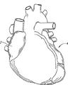
According to this framework, Fig. 1 has shown heart 2, and its blood vessel is the target of one or more angioplasty and/or support implant surgery.Yet, up to the present, still be difficult to maybe can not get into less coronary artery 4.If can get into so little blood vessel and other anatomical structures that are difficult to get into, adopt this system can carry out the treatment of 20%-25% through the cutaneous artery intervention with support or induction system more.This will be the great achievement of human health and can bring the market income---can also avoid patient's income and the productivity's loss.
Characteristic of the present invention is specially adapted to get into system's (though the application of system of the present invention is not limited to this) of little blood vessel." little " coronary vasodilator is meant, the blood vessel of vessel diameter between about 1.5 or 2 to about 3 millimeters.These blood vessels include but not limited to: descending posterior branch (PDA), obtuse marginal artery (OM) and little diagonal artery.Induction system of the present invention can solve like caused other entering of situation such as diffuse Narrowing and diabetes or difficulty of transportation.The field that available this system treats also comprises, vascular bifurcation, chronic entirely shutting (CTO) and prophylactic surgery (like the Stent of vulnerable plaque).
Preferably in this application, adopt bracket for eluting medicament (DES) to help prevention of restenosis.Summary about suitable medication coat and obtainable supplier has introduction in " bracket for eluting medicament general introduction: medicine, releasing mechanism and rack platform " (" DES Overview:Agents; Releasemechanism; and stent platform ") literary composition of Campbell doctor Rogers, to introduce in this description referring to mode.But the present invention also can adopt naked metal rack.
The example of spendable various healing potions includes but not limited in the target prosthese or on the prosthese: antibiotic, anticoagulant, antifungal, anti-inflammatory agent, antineoplastic agent, antithrombotic, endothelialization promoter, free radical scavenger, immunosuppressant, antiproliferative, thrombolytic agent and their combination.Therapeutic agent can be coated on the implant, and is coated on the implant after biodegradable polymer or other suitable temporary carrier mix, and perhaps, when implant is made up of polymeric material, is dispersed in the whole implant.Medicament can be applied directly to rack surface, perhaps introduces to be installed in outside pouch of support at least a portion or the suitable substrate.
Although someone queries specific function and the best applications that also needs further to confirm the self expandable cribbing, to compare with balloon expandable stent, it still has inherent superiority.The balloon expandable stent device can produce " braking mark " damage (be at least do not have through sacculus encapsulate when carrying); And produce terminal peel off or the risk of barotrauma high, this is because the balloon expandable stent distortion is produced when launching when inserting high balloon pressure and dependent interaction power are caused at least in part.
And; Compare with balloon expandable stent; The self expandable cribbing that has suitable development system has one or more following advantages: 1) compare with the system that needs are inserted sacculus, transverse diameter is littler and compliance is stronger, thereby it is better to get into far-end, curved blood vessel, the isostructural ability of little blood vessel; 2) sequential control or " gentle " device launch; 3) if needed, adopt the low pressure sacculus to expand in advance and reduce barotrauma; 4) in some cases,, reduce the amount of " foreign body " material in blood vessel or other body pipes through dwindling the thickness of support bar; 5) because the littler and/or carrying method milder of transverse diameter can be used for neurovascular treatment; 6) can easily the therapy system of a success be amplified with the bigger blood vessel of treatment, vice versa; 7) reduce the complexity of system, all had potential advantages aspect the reliability of system and the cost; 8) reduce neointimal hyperplasia; 9) can adapt to gradually thin anatomical structure, and support does not have additional structure (although still having the choice).
Use the support 10 shown in Fig. 2 A, can realize at least a portion of above-mentioned advantage.Illustrated stent design type is suitable for little blood vessel very much.It can be by collapse to about 0.018 inch of external diameter (0.46 millimeter), or even little of about 0.014 inch (0.36 millimeter)---comprise the limited part/joint that is used to compress it; And can be expanded to (unrestricted fully) about 1.5 millimeters (0.059 inches) or 2 millimeters (0.079 inch) or 3 millimeters (0.12 inch) to about 3.5 millimeters (0.14 inch).
During use, not expansion fully when the size of support is set to when its expansion and fully against blood vessel wall is to provide a radial force (support " oversize " promptly as stated).This power can fixed support, and provide reduce neointimal hyperplasia and blood vessel collapse, or even the tissue that will split follow closely potential advantage in position.
Support 10 preferably comprises Nitinol, and this Nitinol is in room temperature or be lower than and be higher than and all have super-elasticity under the situation of room temperature (being that Af is low to 15 degrees centigrade or even 0 degree centigrade).And, preferably support is carried out electrobrightening, to improve bio-compatibility and anticorrosive, anti-fatigue ability.Support can be the said medicine FirebirdTM.Support can encapsulate with gold and/or platinum, to improve the radiation impermeability, is convenient to the medical science radiography and observes.
To an ability collapse about 0.012 inch to external diameter, be expanded to about 3.5 millimeters support, the thickness of Nitinol is about 0.0025 inch (0.64 millimeter).This support is designed for 3 millimeters blood vessels or other body pipes, can required radial force be provided through preceding method thus.Further information about the radial force parameter of coronary stent; " radial force of coronary stent: comparative analysis " " catheterization and cardiovascular interventional therapy journal 1999 the 46th volume 380-391 page or leaf (" Radial Force ofCoronary Stents:A Comparative Analysis " Catheterization and CardiovascularIntervention 46:380-391 (1999)) introduction is arranged in the literary composition, to introduce in this description referring to mode.
In a kind of manufacture, cut out the support shown in Fig. 2 A with the method for laser or electrical discharge machining (EDM) from circular NiTi tubing, dotted line has been represented to divide around the pattern of pipe.In this method, preferably support is cut into the shape of expansion fully.Compare through the method that thermal enlargement/annealing reaches finally (work) diameter again with being cut into the less pipe that has breach earlier, at the very start support is processed into the method for actual size, just can further carry out meticulousr details processing cutting.Hot forming after avoiding cutting has also reduced production cost and above-mentioned influence.
Fine detail processing for the target support; Can in the close up view shown in Fig. 2 B, see; Axially/be provided with the bridging part (bridge section) 12 of constriction between the adjacent support bar of horizontal direction or the arm/lower limb 14, wherein, support bar forms the network of closed cell 16.This closed cell is designed with and is beneficial to twisting and diminishes, because the disengaging trend radially that causes owing to the combined stress distribution will take place the free-end of open cell (or continuous loop) design.
Yet in some version of the present invention, as represented with broken string among Fig. 2 A, bridging part can cut off strategicly or be open.Do like this and destroyed above-mentioned closed cell pattern, but can improve the compliance of support crooked anatomical structure.Being fit to adopt a kind of situation of this adjustment is to adopt the version of the present invention of sheath or sheath covered stent.In any case for the ease of this adjustment of support, bridging part is preferably wanted long enough, just can in network, form circular fully end as the cell end 18 of not having support/induction system interface feature.
Optional concave-concave profile for support bar bridging part 12; With employing parallel lines profile phase ratio; Its advantage is that it reduces the width of material; Thereby the flexibility that had so both improved support improves traceability and the compliance of support in the object anatomical structure, can select whether to separate/cut off each unit again.No matter be to form circular distal partly or with bridging part 12 connections, support bar bonding part 28 hoops or vertically connect adjacent support bar (as shown in the figure).If there is not bridging part, shown in zone 30, the bonding part can fuse horizontal adjacent supports support bar.
Support 10 is also selected other characteristics for use in support bar bonding part 28.Specifically, support bar terminal 20 is wideer than intermediate supports part 22.In the process of support compression, this being configured with is beneficial to the bending of deflection support bar zone line.For given stent diameter and deflection, support bar is long more, and the pressure in the support is low more, and therefore, compression ratio also maybe be higher.Support bar is short more, and the radial force that is produced during expansion is big more, and the outside loaded toleration of diameter is also big more simultaneously.
In order to improve the compliance of support, make its collapse of can trying one's best, in the design shown in Fig. 2 A, added the stronger support bar terminal 20 of rigidity.Just, the recess 24 between the support terminal 22 is configured to a less angle, just as support in this zone by the part collapse.So when support intermediate member 22 was arranged like this, the less angle of terminal 20 deflections can realize parallel (or almost parallel) arrangement of each several part.In variant of the present invention shown in Fig. 2 A, fillet or arch section 26 engage 28 places and/or the transition that becomes terminal strut angle β (about 30 spend to 10 degree) from middle strut angle α (about 85 spend to 60 degree) be provided from the part of its extension at support.
In addition, before angle α compresses fully, in fact can be built into very approaching with angle β recess 24.Shown in support be not like this.But, the value of doing like this is that through a physics braking is provided, the strain (and stress) in restriction support bar terminal 22 and cell end zone 18 prevents further tension.
In the detail drawing of Fig. 2 B, angle β is set as 0 degree.Adopting obviously thicker end portion 20 to form recess 24 at joint causes forming very little bending along lever arm.The mid portion of support bar is designed to be fit to crooked especially.In addition, 28 turning or crooked 32 places form hinge effect in the bonding part, and support bar can be swung by α around the angle, form the main pattern of support compression.
Other feature of interest in the support Design comprises near-end and far-end induction system interface compatible portion 208 and 210.These elements form in protuberance 212, can be one (for example, when prosthese is made up of the homogenous material pipe, perhaps forming main bodys when a plurality of seal wire type elements are woven, when each element end forms prosthese) with prosthese 82.Perhaps, protuberance is attachable or be connected in support (for example, through welding, adhesives, securing member etc.).In another kind of version of the present invention, protuberance comprises the polymeric material that is coated on the prosthese 82.Other structural model also is possible.The further details of protuberance and each compatible portion is discussed in more detail below.Here be confident in saying that element enough " soft " and/or be circular with tissue formation antisitic defect interface at two ends.
Stent design among Fig. 3 A and the detail drawing 3B is compared with the stent design shown in Fig. 2 B with Fig. 2 A, and existing certain similarity exists some obviously different again.The same with aforementioned variant, support 82 has the bridging part 42 of constriction between adjacent supports bar or arm/lower limb 44, and wherein, support bar forms the network of closed cell 46.In addition, the end 48 of closed cell is preferably fillet, and to avoid causing damage, for example compatible portion 208,210.
In addition, in order to improve compliance, can the bridging part 42 of support 82 be separated.In addition, can also use (aforesaid) other modes to improve, perhaps even with it removal.And, to plant in the design at each, the unit overall dimension of decision axial length and/or diameter also can be had nothing in common with each other with element number (representing with transversal level with vertical among Fig. 3 A).
The same with the aforementioned brackets device, support bar terminal 50 is wideer than intermediate supports bar part 52.Yet, comparing with Fig. 2 B, the angle β among Fig. 3 B is bigger.Do not have the stronger outer support bar part of hinge fraction and rigidity in this structure.But the angle β in the design of Fig. 3 A/3B can collapse, support bar terminal with intermediate support part synergism, bend, make type, the formation teardrop shaped space between the adjacent supports bar usually of roughly being in line behind the support collapse.This method can form the radius of curvature that stress reduces in the support bar junction, and support at utmost compresses.
Be cut in actual size or the support near actual size at one, support bar has constituted " S " type curve (shown in Fig. 3 A and 3B).Preferably confirm curve through himself characteristic in physics or the computer model, device can be launched into final expansion state from required compressive state.Obtaining support like this can be extruded or collapse under the effect of power, and a firm as far as possible or smooth and/or columniform outer surface section is provided.This effect produces strain to form required compression and expansion shape through disperseing the stress of extruding.One or many expansion and hot forming circulation can cause the quality degradation of superelastic nickel titanium alloy timbering material originally, and this interaction energy makes device not influenced by expansion and hot forming circulation." S " type holder device that adopts about the present invention reaches the further information that substitutes Framework construction; The United States Patent (USP) provisional application of having submitted on October 14th, 2004 the 60/619th that is entitled as " minute vessel stent device "; Open in No. 437, to introduce in this description referring to mode.
In use of the present invention, find that the design of Fig. 3 A and 3B not only can be compressed to closely knit cylindrical cross section, and when twisting, also keep this shape.Do not receive concrete theoretical constraint, but, believe preferred this device under the twisting pattern because this device can provide utmost point uniform stress distribution when simple compression.Like this, though can adopt the cantilever type shown in Fig. 2 A-3B separately in any system as herein described, the preferred a kind of design in back.And, can expand the mode of generation " S " curve, like this, the analysis that is used to produce cutting (as-cut) (or near cutting) structure of special generation twisting design will become some version of the present invention.Specifically, physics capable of using or computer model make support expand from ideal compression, form required non-compressed stent geometry.
In any case obtain,, hope to prebend shape for making support clear compression when the twisting.In other words, support is configured to when its twisting, each element change of shape before the twisting be shown in straight configuration.The shaping degree that generation compacting twisting is dwindled can be form, S-curve or other shape of simple bias or spiral.
Because above-mentioned each support Design considered debatable strain (under latter event, in fact having adopted same method so that the compression profile of improvement to be provided), support can reach very high compression ratio, can be from about 5 times to about 10 times or higher.And, but their twistings are many times to keep the conveying profile of compression.Realize that the required twisting number of times of this effect depends on stent diameter and length and different.Treat the situation of 3.0mm blood vessel for the 28mm support, need carry out three times or four twistings.Similar diameter, short support need the rotation of less number of times pari passu, and the less support of diameter also is like this usually.
No matter the design of selecting how, said design is significantly shortened separately when it should be noted that from the expansion of compression profile.In essence, support bar causes length variations with respect to the angle variation of tubular body axis.Therefore, the degree of shortening will depend on the combination of following factor: the quantity of repetitive in support bar length and angle and the design.It is discussed in more detail below that obtaining of using among the present invention shortened the mode of configuration.
But before discussing, it is big or small accordingly to notice that system of the present invention should be arranged to existing seal wire size.For example, the cross-sectional profiles of system (crossing profile) can be about 0.014 inch (0.36 millimeter), 0.018 inch (0.46 millimeter), 0.022 inch (0.56 millimeter), 0.025 inch (0.64 millimeter).Certainly, system also can be median size, especially as far as custom-built system.And system also can be arranged to French (French, FR) size of magnitude.In this case, system dimension is at least about 1 to 2FR, and the balloon expandable stent induction system of known minimum is of a size of about 3 to 4FR.When device total cross-sectional profiles and known seal wire size are complementary, just can be with using like ready-made elements such as sacculus and microtubulars.
At least when being made for minimum dimension (no matter be evenly/standard guide wire or FR level, or other), system can carry out a kind of brand-new support and launch pattern, promptly support passes angioplasty balloon catheter or little microtubular chamber is carried.Deep layer discussion and the details that carry in " through the chamber "; U.S. Patent application the 10/746th in December in 2003 submission on the 24th; The PCT of No. 455 " based on the stent delivery system in foley's tube chamber " and this patent submission on March 23rd, 2004 applies for that introduction is arranged in US2004/008909 number, all to introduce in this description referring to mode.
The system of large-size (being that cross-sectional profiles is more than or equal to about 0.035 inch) is applied to peripheral blood vessel more, and hereinafter will specify.But, even, also preferably use diameter to be about 0.022 to 0.025 inch stent delivery system in " little blood vessel " case or in using (blood vessel diameter of required treatment is about 3.0 millimeters).This system can cooperate conduit to use, and the seal wire of said conduit and diameter 0.022 and/or 0.025 inch is complementary.
Though this system is inappropriate for the very little blood vessel of entering, compares with known system, this variant of the present invention has suitable superiority aspect the bigger little blood vessel (being that diameter is more than or equal to about 2.5 millimeters blood vessel) getting into.As comparing, known minimum band seal wire induction system has the MicroDriver of Medtronic Inc. (Medtronic) TMThe Pixel of system and guide company (Guidant) TMSystem.These systems can be used for treating 2 to 2.75 millimeters blood vessel, and the cross section profile of a back system is 0.036 inch (0.91 millimeter).No. 2002/0147491 described system that is used to treat little blood vessel of United States Patent (USP) imagines it and can narrow down to 0.026 inch of diameter (0.66 millimeter).In addition, because the core component of apparatus of the present invention can (with such or such mode) use as seal wire after slits, the present invention also has other advantages, will further illustrate in the back.
Of preamble, possibly need a kind of variant of design system of the present invention, be used in organ stent than trunk, peripheral blood vessel, bile duct or other hollows.This application comprises support is placed in the zone that diameter is about 3.5 to 13 millimeters (0.5 inches).In this case, preferably using diameter is the cross section profile system of 0.035 to 0.039 inch (3FR), expands (separating compacting) to going out about 0.5 millimeter to 1.0 millimeters size greatly than blood vessel of being treated or hollow body organ at this system's medium-height trestle.Support model among Fig. 2 A/2B or Fig. 3 A/3B can realize easily that support fully expands.
Also have, as relatively, for the slits of treatment than major diameter blood vessel or bile duct, known minimum delivery system is 6FR system (specified external diameter is 0.084 inch), is applicable to the guiding catheter of 8FR.Therefore, even large-size, the present invention also can be made for the induction system of seal wire size range commonly used, and this is still impossible before this, and the present invention simultaneously also has the described superiority of this description.
About the method for the system of the present invention that uses optional configuration, Fig. 4 A-4L has shown the example of a revascularization.And described induction system of this description and support or implant can also use other modes to use---especially according in this description especially referring to method.
Get back to Fig. 4 A, it has shown that coronary artery 60 is partially or completely blocked by speckle at treatment site/damage 62 places.In this blood vessel, seal wire 70 is with the direction process treatment site towards far-end.In Fig. 4 B, through having the foley's tube 72 of sacculus most advanced and sophisticated 74, the sacculus part is alignd (balloon catheter shaft of adjacent balloon shows with profile, has seal wire 70) with injury region on the seal wire.
Shown in Fig. 4 C, in the angioplasty process, the blood vessel in damage 62 zones is opened in sacculus 74 expansions (expanding or expansion).This balloon expandable can be called as " expanding in advance ", is following support after explaining and is placing, and optionally having " expanding in a back " balloon expandable process.
Then, for compatible system (can pass the system in foley's tube chamber), sacculus part at least dwindles and to front transfer, crosses expansion fragment 62 ', shown in Fig. 4 D.Here, seal wire 70 that kind shown in Fig. 4 E is removed.As described further below, seal wire 70 is carried delivery guide member 80 replacements of support 82.Fig. 4 E and 4F have shown this replacement.
Yet, preferably need not carry out such replacement.And hope that more original guide wire apparatus is exactly a member 80 in the foley's tube (or any other conduit), rather than the standard guide wire shown in Fig. 4 A 70.Like this, can dispense the step shown in Fig. 4 E and the 4F (therefore, also can remove this two figure).
Perhaps, can before expansion step, replace the seal wire of induction system.Another selection is, is used for preparatory expansible foley's tube with a new conduit replacement, carries out back expansion.
In addition, promote foley's tube with the step of Fig. 4 D and advance that cross damage perhaps be otiose, because this placement is just crossed damage and avoided touching damage position through moving seal wire.Fig. 4 G has shown next step operation in either case.Specifically, extract foley's tube and make its far-end 76 remove damage.Preferably, delivery guide member 80 keeps fixing, invariant position.After sacculus retracted, conveyer device 80 also was pulled, and support 82 is positioned at the desired position.Yet, be noted that it can be simultaneous recalling, and combines the operation described in Fig. 4 G and the 4H.Case whatsoever, the doctor generally can skillfully operate and realize this collaborative moving through the one or more radiation impermeability characteristics on observation support or induction system under the medical science radiography.
In case expansion fragment 62 ' is crossed in the support placement, support begins to launch.Unfolded mode will be set forth hereinafter.Shown in Fig. 4 I, once expansion, support 82 is in the shape of part expansion at least on the corresponding position of compression speckle.Next, shown in Fig. 4 J, through sacculus 74 is placed in the support 82, the both expands, and expands thereby form above-mentioned back.This process is expandable stent further, and near the speckle being pressed into helps to fix.
Certainly, might not to import sacculus again in order expand in the back, but preferably to do like this.In any case,, just accomplished the angioplasty and the support of the injury region of blood vessel 60 and implanted in case shown in Fig. 4 K, pulled out induction system 80 and foley's tube 72.The detail drawing of Fig. 4 L has shown the support of a placed in position and has been in support, opens the required result of blood vessel form.
In addition, the present invention also can be used for " directly Stent ".That is to say, do not adopt the said sacculus angioplasty in front, play the unimpeded effect of body pipe that keeps through independent transfer gantry.Likewise, in case after having carried one or more supports with this system (can be to use individual system, also can be to use a plurality of systems), carrying out above-mentioned back expansion process has been optionally only just.In addition, other purposes can also be arranged, for example in the tubulose organ of hollow, implant a grappling cribbing, a plurality of supports etc. are isolated, carried to aneurysm.When implementing various above-mentioned or other operations, need carry out suitable modification to this method.Here given operating process is an optimal way of embodiment of the present invention, and the present invention can also have application widely.
Get back to Fig. 4 L, support 82 comprises near-end 202, far-end 204 and the supporting construction 206 of extending therebetween.Supporting construction 206 is configured to that diameter reduces when near-end 202 rotates with respect to far-end 204.Support 82 also comprises protuberance 212, when support is in that twisting diminishes or support is retained on the induction system during compressive state.Protuberance 212 comprises near-end compatible portion 208 and far-end compatible portion 210, and prosthese 82 is retained on the induction system.
Given implant can have a plurality of protuberances 212, and each protuberance has different shapes rather than single configuration.Typically, the support both sides have at least two protuberances separately.All have protuberance if not each support bizet, protuberance should center on support periphery equi-spaced apart basically, with the load on the uniform distribution support.In this case, protuberance aligns each other (shown in Fig. 4 L) or centers on the support axis along the support axis and interlocks.More typically, each bizet has protuberance and matching characteristic.Like this, support in the pure twisting pattern that the diameter that is used for carrying reduces, is not had element to have the trend that breaks away from transfer guide by constraint fully.And, consider to take out alternate arm and partly reduce hat number of packages amount, make every end four hat designs change two hat designs into.Like this, can use less protuberance, for each full unit a protuberance is provided still at the support two ends simultaneously.
Tab length is different, depends on the interface that it had or formed or the form of compatible portion particularly.The length of protuberance should be able to make load effective transition or be transferred to support of twisting, and the minimum that takes up space.Though also must get rid of outside the present invention, in the application of attempting, possibly have around the trend of delivery device body distortion or twisting than a longer protuberance of element length.This characteristic possibly cause undesirable size adjustment and/or operating difficulties.
With reference to figure 5, the compatible portion 208,210 of support 82 has the shape in the pedestal 162,164 of the system that can be nested in 100.The shape of protuberance 212 includes but not limited to that " L " shape, " T " shape, " V " shape, circle, rectangle, square, polygon, diamond, triangle, elongated shape and fluting protuberance 212 are as compatible portion.In fact, protuberance can be taked arbitrary shape, as long as the support that they can make twisting diminish in the state is retained on the induction system.And, if the protuberance 212 on support 82 is not necessarily identical shaped.But protuberance 212 shapes on every side stand can be different separately.And protuberance can have the unique shape that is different from adjacent protuberance.
In any case the protuberance 212 that prosthese 82 two ends should be extended sufficient amount at least makes prosthese 82 keep reducing the required power of diameter during with the balance twisting.For design less in some system (being that cross section profile is the induction system of 0.014-0.016 inch), each side of implant exists few to two matching characteristics.Along with the increase of reduced size, can add more protuberance/matching characteristic.
Can make it be fixed in induction system through twisting (twisting at least in part) support 82 before being loaded into support 82 on the induction system.Perhaps, can the support 82 of expansion be set on the induction system core element, the twisting support is brought in around induction system compressed stent 82 for 82 liang then.And; Support is suitably fixing or be pre-loaded in sleeve pipe or a plurality of sleeve portion of twisting each other and will help to make support to center on the induction system loading; As be entitled as the U.S. Patent application sequence the 11/265th of " indirectly implant delivery system whether "; No. 999 said, and its content is introduced in this description with the mode of reference.Certainly, can revise said method with the system that adapts to this list of references and the difference between system of the present invention.
In the general description of induction system of the present invention shown in Figure 5, induction system 100 has the support of collapse configuration in the far-end 102 places load of elongate body.In this embodiment, the twisting support is covered by total length sheath 104.Support is in the twisting configuration, and the preliminary motion of sheath is easy at least.In other words, because the twisting power that support is applied in remains on the collapse configuration at least in part, support can not promote sheath or against its strain (perhaps can not take place) with same degree, thereby has reduced friction at the interface.Therefore, can remove the sheath (or first at least moved further sheath) of covering with respect to simple sheath type induction system with being more prone to.For example, if can rotatably controlling (for example, through the handle knob, other embodiment that vide infra and detail) each other, key/base part, then can thoroughly take off sheath from the support of twisting at least in part so that support remains on the collapse configuration.Diminish with no sheath twisting that hereinafter provides and to compare, the sheath of covering provides extra safe clearance.
Be described below, the invention provides other and make support keep characteristic or the mechanism that diminishes.In any case transfer guide preferably includes/comprises various types of flexible anti damage distal tips 108.
The other end at conveyer device can be provided with handle 110.Handle main body 112 can comprise one or more levers or slide block 114 or other device (for example trigger, knob or wheel disc), is used to start the taking-up of optional sheath/limited part or core element.The conveyer device handle can comprise that locking piece 116 is to prevent accidental activation.Similarly, handle 110 can comprise that various safety or stop feature and/or ratchet or clutch mechanism are to guarantee one-way movement.Handle 110 also comprises knob 124, is used for twisting/separate and turn round support.Certainly, can provide other optional interface device to realize this effect.
And, active interface element 118 can be provided so that handle is taken off from induction system near-end 120.Interfacial phase is lockable for main body, preferably includes to be used for handle unfolded internal feature on the transfer guide.In case accomplish, can be with the seal wire of second length 122 attached or " fixing (dock) " to the induction system near-end, this combination is as " exchange length " seal wire, thereby is convenient to replace foley's tube or carries out other operation.Perhaps, intrasystem core element can be an exchange length seal wire.
Fig. 5 has also shown the packing 150 that contains at least one induction system of rolling 100.This packing can comprise one or more outer boxes 152 and one or more inner pallet 154,156, has peelable cover layer commonly used in the medical device products packing.Certainly, also comprise operation instruction 158.Such explanation can be the print product in the packing 150, perhaps provides with another kind readable (comprising computer-readable) medium.The basic operation content that has comprised said device and correlation technique is described.
For supporting above-mentioned application, should be understood that and can adopt various radiation impermeability labels or characteristic in the system with 1) confirm backing positions and length, 2) indicating device starts and slits, and/or 3) far-end of location transfer guide.Therefore, can comprise various platinum (or other radiation impermeability material) band or other label (for example tantalum bolt) in the system.Especially in the time of after used support launches, can shortening to a certain degree taking place, the desired location (with respect to guide) of the support after also hoping to make radiation impermeability characteristic and launch is alignd.For this reason, radiation impermeability characteristic is set on the conveyer device core element of mount proximal end and far-end.
Fig. 5 has shown full-scale induction system, and several follow-up accompanying drawings have shown the detailed view of system's 100 far-ends 102, has described the method that the many fixed supports releasedly of the present invention are used to carry.Device characteristic typically is combined in the holonomic system, can be in this way and the alternate manner that it will be apparent to those skilled in the art that use.
Therefore, Fig. 6 has shown the far-end 102 of induction system, comprises prosthese (for example support) 82, on it is set in the inner member below the support.As stated, prosthese 82 comprises near-end 202, far-end 204 and the supporting construction 206 of extending therebetween.As stated, supporting construction 206 comprises grid, grid, fabric or other similar structures that diameter reduces when near-end 202 rotates with respect to far-end 204.Excellent intensity is provided after the expansion of this structure and has evenly supported, but the shortening of coil brace when the collapse configuration is expanded can not take place.
Prosthese 82 also comprises protuberance, and prosthese is retained on the induction system 100.Shown in protuberance comprise near-end key, interface or compatible portion 208 and far-end key, interface or compatible portion 210.Interconnect or each other coupling so that support is retained in the various structures of pedestal and compatible portion on the elongated member is regarded as prosthese is retained in the variety of way on the elongated member as herein described.The example sketch map of bracket side coupling/interface feature is shown in Fig. 8 A-8D.
Complementary base is presented at various sending in the targeting part.For example in Fig. 6 and 7, the pedestal 162,164 of system 100 is admitted the hook or the L-shape compatible portion 208 and 210 of Fig. 8 A shown type separately.
Fig. 7 has described the variant of system shown in Figure 6, and this figure does not show that prosthese is to set forth each element better.As shown in the figure, inner member 170 extends through the system 100 of at least a portion.It should be noted that inner member 170 can comprise coil seal wire, core silk or extend through whole system 100 or other element of at least a portion system.The far-end of the far-end construction system 100 of core element 170 comprises coil most advanced and sophisticated 172 or other atraumatic tip, is used to guide pass careful body structure (for example peripheral blood vessel or other vascular, conduit path etc.).Core element 170 comprises the part that is used to install prosthese, and this part is tapered from the remainder of core.In addition, in order to adapt to coil tip 172, core element 170 also can comprise one or more extra tapered segment, to allow the adjustment system flexibility and/or to comply with the structure at coil tip 172.
Fig. 7 has also shown the far-end pedestal 164 that is associated with core element 172.Pedestal comprises that shape can admit the geometry 168 of prosthese far-end compatible portion.Far-end pedestal 164 is can be with core element 170 integrally formed or be fixed in core element.
Near-end pedestal 162 comprises receptacle 166, and its shape is fit to admit the near-end compatible portion of prosthese.As shown in the figure, near-end pedestal 162 is formed by the far-end of the outer member 174 that at least a portion core element 170, extends.In this variant, core element 170 is removable with respect to outer member 174.In a kind of variant, core element 170 is rotatable with respect to outer member 174.Alternatively or in addition, core element 170 can move axially with outer member 174 each other.This characteristic is useful for maintenance and/or deployment prosthetic, is described below.
Core element 170 can be elongated, has relative smaller effective diameter.It has the effect that permission is delivered to select location with prosthese and during being provided with and implanting, supports the prosthese of compressed format.Core element can be for solid, maybe can have a cavity through this core element, depends on factors such as type such as required flexible degree, relevant releasing mechanism, constituent material.The tip of core element (being the far-end of induction system) can comprise atraumatic tip, and for taper and/or linear, bending or J-shape, and this depends on the factors such as degree such as the anatomical structure of doctor's preference, pipe or area-of-interest, required hardness.
As described herein, induction system of the present invention 100 adopts prostheses 82, and its diameter when first direction rotates relatively reduces when the prosthese two ends.Therefore, when the compatible portion 208,210 of prosthese is nested in near-end and 162,164 last times of far-end pedestal, the near-end of prosthese 82 and far-end 202,204 restricted or can not along the second direction rotation with the expansion prosthese when the healthcare givers needs.For the ease of the restriction prosthese, core element 170 locks to prevent its relative motion with respect to outer member 174 releasedly.Therefore, when needing, core element 170 can dissociate with outer member 174 so that prosthese is separated turns round and expanded in diameter (for example, when prosthese itself is expanded).In variants more of the present invention, the healthcare givers helps expand prosthese through making core element 170 with respect to outer member 174 rotations.
Outer member 174 will help to limit or help the expansion of prosthese with respect to core element 170 axially movable abilities.For example, variant of the present invention described herein can be dependent on far-end pedestal 164 and to moving of far-end the protuberance of prosthese is broken away from respect to near-end pedestal 162 from pedestal.Perhaps, when protuberance was hook or L-shape, far-end pedestal 164 moved causing prosthese axially " elongation " to far-end with respect to near-end pedestal 162, and this resists false intravital any internal bias and expands.The motion that should be understood that pedestal can realize through any-mode.For example, core element can advance with respect to the near-end pedestal.Perhaps, near-end pedestal (or outer member) relatively the far-end pedestal retreat.
As stated, near-end and far-end pedestal 162,164 have the receptacle 166,168 that shape is fit to the compatible portion 280,210 of admittance prosthese separately.The geometry of receptacle can comprise a plurality of openings (as shown in the figure), the one or more protuberances on its shape receivability prosthese.Opening portion extends to a certain degree of depth (promptly forming pocket).Perhaps, opening is extensible passes whole element.Said to protuberance like preceding text, the shape of opening includes but not limited to: " L " shape, " T " shape, " V " shape, circle, rectangle, square, polygon, diamond, triangle, elongated shape and fluting shape.
Fig. 8 A-8F has shown the variant of protuberance 212 among the present invention.Fig. 8 A has shown " L " shape protuberance.Fig. 8 B has shown rectangle protuberance 212.It should be noted that Fig. 8 B has also shown the protuberance 212 that has recess 214 alternatively.This characteristic provides extra compliance through the material of removing the protuberance junction, thereby helps the adjacent supports bar 52 of compressed stent.Fig. 8 C has shown " T " shape protuberance 212.Fig. 8 D and 8E have shown lobe and " V " shape protuberance respectively.Fig. 8 D has also shown an example of radiation impermeability label 216 (for example, tantalum bolt).Protuberance can align with support bar/unit geometry, or by its skew.Through squint whole protuberance and/or its part (for example, shown in Fig. 8 A variant), this characteristic can be resisted the trend that the guide body element is carried in disengaging that support end or protuberance itself cause owing to the twisting effect of being given more valuably.
Perhaps, zone 216 can be opened and form the compatible portion that negative space (negative space) is limited.In this case, the compatible portion of protuberance comprises receptacle, is used for admitting pin or other element (the pedestal interface on the induction system).Fig. 8 F has shown a similar mode, be negative space 216 are parts of " C " shape support unit geometry.Regardless of structure, can adopt various positive or negative interfacial process.In fact, form on the protuberance or can have many different shapes by the compatible portion that protuberance forms, as long as they help to link to each other with complementary induction system hardware.
In addition, single prosthese or support can have the protuberance of any amount different shape, unacceptable interference or contact can not take place between the protuberance when needing only compressed stent.Therefore, should be understood that the shape of protuberance and configuration can change according to multiple factor (for example, concrete application, stent size, vascular torsion resistance etc.).Therefore, except that shape as herein described, protuberance also can comprise the configuration (no matter shape is still obviously stretched out along three-dimensional near the plane) of hook, fork, opening, bag, key, grasper, tooth, rod or fluting shape.According to foregoing, select corresponding pedestal characteristic to adapt to the shape of each protuberance.
Under any circumstance, select the shape of protuberance, thus the excessive risk that does not cause the patient to damage.For example, for vascular applications, the shape of protuberance must be chosen to can not cause the excessive wound of blood vessel wall.On the other hand, possibly there is not this risk in non-vascular applications.Therefore, this protuberance design has aggressiveness more in the support of specifying vascular applications.
As stated, the present invention considers to use one or more sleeve pipes (as shown in Figure 5) that cover implant fully, or keeps to help making support center on system around mount proximal end and/or far-end.The optional variant of induction system 100 adopts the support of no any further sleeve or limited part, and is as shown in Figure 6, and other, comprise the variant shown in figure Fig. 9 A.
In Fig. 9 A, induction system terminal 102 adopts the elongated protuberance 212 that is nested in near-end and the far-end pedestal 162,164, and pedestal has " flute profile " opening 166,168 to hold elongated protuberance.Relatively near-end pedestal 162 rotation far-end pedestals 164 are turned round support 82 to separate, and protuberance 212 are slided or (radially outward) discharges from pedestal, with deployment prosthetic or support 82.Alternatively or Combined application, near-end and far-end 162,164 can be each other away to discharge self expandable type support 82 from limited part.In this case, support 82 is in case discharge from limited part, promptly separates to turn round and expand.
Fig. 9 B has shown system interface mode shown in Fig. 9 A, has increased at least one near-end and far-end (or first and second) sleeve pipe or protecting band 176,178.It should be noted that and for clarity sake drawn transparent casing.But sleeve pipe can be transparent, opaque, radiolucent or other visible form.Need sleeve pipe to provide to prevent the additional degree of security of the improper release of support.Sleeve pipe guarantees that protuberance 210 can not deviate from its pedestal (when for example extremely twisting) separately.But, support only separate when turning round at support discharge (causing shortening and coming off) or user through handling induction system 100 from base-separation.
Release can take place at two ends simultaneously, perhaps carries out stage by stage.For discharging stage by stage, to use to break away from it separately during the elongated member of pedestal, the length of implant both sides protuberance can be different.Suppose that the rate of withdrawal equates, a then short end relatively early withdraws from, and makes the long element of at least a portion keep engagement.Perhaps, long end is owing to have a relatively shorter end and have higher static friction and keep fixing, and an end of weak point at first withdraws from simultaneously.Which kind of situation no matter, the position through handling induction system (for example, moving to discharge the proximal lateral or move to discharge the distal side to far-end to near-end) can discharge the remaining side of implant.Perhaps, support is expanded from the release of first side and possibly caused support second end to shorten and/or the angle variation, and it is self-deployed with sequential system.In the another kind of mode that support discharges in proper order, the protuberance shape of both sides has nothing in common with each other, and opposite side withdraws from through the reservation of internal lock interface to make a side.This system is as further described below.
Fig. 9 C has shown another kind of variant, adopts significantly different implant release mode alternatively.In this variant, system terminal 102 comprises near-end and far-end pedestal 162,164, comprises separately near-end and distal openings 166,168 with " L " shape opening.Support 82 comprises " L " shape protuberance accordingly.For stent 82, near-end and far-end pedestal 162,164 rotation and make support 82 cardiectasis therein relatively.This effect can cause compatible portion to break away from its nested region.Perhaps, in case through separating merely after the center of turning round expandable stent 82, user moves together by pedestal and makes protuberance break away from pedestal and make medicated cap spare and sleeve portion 176,178 is out of shape.
Therefore, sleeve pipe in the variant or medicated cap spare shown in Fig. 9 C must have enough flexibilities or fragility/splitting property and deviate to allow compatible portion.Except as otherwise noted, sleeve pipe 176,178 should be configured to allow protuberance to leave opening.Along with the shortening of support, protuberance passes sleeve portion 176,178 with contraction usually.Different is that sleeve pipe shown in Fig. 9 B in the variant of the present invention or medicated cap spare 176,178 can be flexibility or rigidities, do not discharge the initial axially compatible portion of locking because do not need it to be out of shape.
Figure 10 A has shown a kind of variant of induction system of the present invention, and terminal 102 are fit to adopt support, and the protuberance at its main body two ends has different configurations.In the embodiment shown, near-end and far-end pedestal 162,164 are admitted support 82, and support 82 comprises the elongated protuberance 212 of far-end 204 and hook (have and stretch out planar hook portion) or " L " shape protuberance 212 of near-end 202.As stated; At the expansion process of this variant medium-height trestle through to carry out down: far-end pedestal 164 (or core element) axially breaks away from the protuberance 212 of rack far end 204 away from motion with respect to near-end pedestal 162, and the protuberance of near-end 202 still is engaged in the near-end pedestal 162 simultaneously.Then, in case discharge from tension force/twisted state, near-end key/engaged element discharges from pedestal.Though the expansion of support will cause desirable from distal-to-proximal expansion usually near taking place simultaneously.
Figure 10 B has shown to have the system that is similar to end 102 shown in Figure 10 A, has just increased sleeve pipe 180, and sleeve pipe 180 can slide in a part of system 100.In this variant, system also comprises distal cannula or medicated cap spare 178.Yet, can consider that sleeve pipe 180 extends on the length of entire bracket 82, to use sleeve pipe or medicated cap spare need not in the said system of preceding text Fig. 5 as sheath.Sheath can be made up of flexible polymeric materials or other material.
In Figure 10 B shown device, expansion process comprises: near-end pedestal (with sleeve pipe 180) is moved at first to discharge slidably protuberance 212 of far-end pedestal 164 places with respect to far-end pedestal 164.At this moment, support untwists and expands.Then, sleeve pipe or sheath 180 are recessed so that protuberance is discharged from near-end pedestal 162.(telescopic at least far-end have bond structure and can be) in this embodiment, to the such automatic release of variant of the present invention shown in Fig. 9 C.In this configuration, sleeve pipe or sheath 180 provide " safety " of long-range actuating to guarantee, avoid support to launch, when the healthcare givers hopes.
Figure 11 A has shown the detail drawing of the said system 100 of Fig. 5, wherein, can support 82 be twisted to the configuration that diameter reduces, and support 82 can be covered by the sleeve pipe that can on support, slide 180 at the far-end 102 of system.One or more sleeve portions cover most of or whole support basically, and support need not twisting and diminishes and compress required degree when not having sleeve pipe fully.
Figure 11 B and 11C have shown the mode that is similar to Figure 10 B and 9C respectively.The main distinction is that the variant of Figure 11 B and 11C comprises long sleeve pipe 180, partly relies on it to keep the compression diameter of support.As shown in the figure, when sleeve pipe 180 was recessed, support 82 outwards protruded.Can adopt this mode to realize that support discharges and do not need any rotation of transfer guide to control.But leaving the far-end pedestal through shortening support, rack far end promptly can removed sleeve pipe 180 backs from discharging.
Perhaps, induction system more is similar to simple shield system shown in Figure 11 A-11C.In other words, put on the twisting of support can be before inserting main body or sheath 180 directly apply before removing.Like this, utilize the twisting of rack body, reduce support and be applied to the outside power on the sleeve pipe, the friction that the support that the twisting that puts on main body will help to destroy any static friction and/or reduce sleeve pipe 180 causes.Then, user can remove Decanning 180 with less power.
Under any circumstance, Figure 11 B has shown a kind of variant, and wherein, another sleeve pipe 178 is positioned at the far-end of support 82, and far-end pedestal 164 allows support 82 from discharging.When sleeve pipe 180 when support is removed, support 82 expands or expansion, make its shortening and from far-end pedestal 164 from discharging.In case it should be noted that the near-end of support 82 can be designed to remove sleeve pipe 180 and promptly discharge support 82.Perhaps, the near-end of support 82 discharges when the remainder of support 82 is expanded to a certain size, makes near-end break away from near-end pedestal 166.
Figure 11 C has shown the variant that is similar to Figure 11 A and 11B, and another sleeve pipe 178 is positioned on the support 82.In this variant, system comprises another deformable sleeve pipe 178.When sleeve pipe 180 when the far-end of support 82 is recessed, support 82 expands and causes 178 distortion of deformable sleeve pipe.This effect makes the far-end of support 82 discharge from far-end pedestal 164.As stated, in case also can being designed to remove sleeve pipe 180, the near-end of support 82 promptly discharges support 82.Perhaps, the near-end of support 82 discharges in the time of can being expanded to a certain size at the remainder of support 82, makes near-end break away from near-end pedestal 166.
Figure 11 D has shown the variant with the sleeve pipe 180 of the said system of Figure 11 A-C coupling.As shown in the figure, sleeve pipe 180 can be fabricated in the casing wall or just below casing wall, comprise one or more seal wire or silk 182.In the practice, the healthcare givers spurs seal wire/silk thread, in sheath, forms a breach to allow the expansion of (or making) support.In an optional structure, to tear seal wire 182 can be the main body below and wrap up suture thigh or other silk thread of main body, as shown in the figure.Figure 11 E has shown the another kind of variant of sleeve pipe 180, comprises the part 184 of turning up that self is folding.When standing the expansionary force of support along with the expansion of support, sleeve pipe can curl backward.This structure provides the optional form that adopts flexible sleeve 184.
In another kind of mode of operation, the part 184 of when sleeve pipe 184 rollbacks, turning up is turned up.As shown in the figure, the part of turning up can comprise a plurality of independently elements.Perhaps, sleeve pipe 180 is whole, and jacket exterior and valgus are divided each other coiling at interval.And,, consider when sleeve pipe 180 near-ends are retreated the part of turning up tear-off opening and form each section especially for the minor diameter induction system.Material has in advance scratch or otch so that above-mentioned effect, is used for reducing firmly or adapts to roughly non-elastic material from curling to relatively large diameter than minor diameter.
The design of other induction system is shown in Figure 12 A-14B.Described in other system of this paper, maintain the radial dilatation type prosthese (for example support) of collapse configuration on these induction systems, (at least in part) with tray deck around or twist into the compression profile and realize carrying.In certain embodiments, support comprises protuberance, and protuberance is nested on the pedestal of induction system.Do not have in those variants of above-mentioned protuberance at implant, carry pedestal to be configured to and directly to link to each other with support.
Figure 12 A and 12B have shown first variant of these devices, wherein, have or do not have protuberance on the support.Described in other variant of the present invention, transfer guide 182 preferably includes an atraumatic tip 1202.The pipe of device or the main body or the bar axle 1204 of sleeve pipe form comprise hook 1206 at far-end.Main body preferably is made up of hypotube, so that hook is integrally formed with it.
The near-end of support and far-end compatible portion can be arranged in the opening or the interior depression (for example, referring to Fig. 8 D and 8E) that forms of support protuberance in the unit structure, and these openings or depression adapt to the near-end and the far-end pedestal of transfer guide 1800.In this variant, the near-end pedestal comprises the complementary base hook 1206 ' that is formed by hypotube.Hook 1206 ' is positioned at the far-end of hypotube, is supported by core element 1208.Hook 1206 ' can be connected shaping with ring 1210 or otherwise provide.Under any circumstance, hook (common every side at least two with equilibrant) has the fork 1212 and depression 1214 that is fit to admit support.One group of complementary hook 1206/1206 ' forms near-end and the far-end pedestal of admitting support together, and stretching support and make it when axial stretching, extension or extension and twisting, remain on the collapse form is shown in Figure 12 B.Perhaps, can adopt the twisting pattern of compression or maintenance support separately.But, should be understood that in some load scheme hook interface (shown in Figure 12 A and 12B or Fig. 6 and 7) are very useful.
In any case, hook do not have overhanging shown in the configuration (so that support release), system depends on friction between support and the hook support is held in place when the support circumferentially extending.But, the interface feature between support and the hook can be provided so that control.No matter which kind of situation realizes that through tension force and/or torsion that release makes support remain on the collapse profile support discharges.
In variant of the present invention shown in Figure 13 A and the 13B, transfer guide 1300 is provided, it preferably includes atraumatic tip 1302 equally.And, main body or bar axle 1304 (preferred hypotube) and core silk element 1308 are provided.Yet, in variant shown in Figure 13 A and the 13B, and adopting that radially hook is different as pedestal, near-end and far-end pedestal comprise radially screw thread appearance grasper 1306 and 1306 '.In the proximal lateral of device, show that they and hypotube are integrally formed.They then are configured to and encircle 1310 and link to each other at far-end.
Shown in Figure 13 B, grasper (every side from least one to a lot of) is captured the support with the shape complementarity that is fit to compatible portion or the key 1314 of coupling in grasper slit 1316 as tooth.Utilize its support protuberance and the complementary angle component of carrying director element to intersect, these elements can be as thread interface " interlock " to strengthen its combination.But system is slightly different shown in this system and Fig. 6 and 7, depends on flag-shaped or flat hook component.
Shown in another kind of induction system, in system, apply moment of torsion and make the support collapse or keep the collapse state at least to realize conveying.In addition, support can be under the tension force, and the core silk is pushed away (or opposite action) forward with respect to hypotube.Certainly, removing winding and/or lower pulling force can realize discharging.Which kind of situation no matter, support can expand and through radial dilatation from groove 1314 release keies 1314.
Last based on the example of the downtrod support of twisting shown in Figure 14 A and 14B.Figure 14 B has shown that the chuck type carries the detail drawing of guider pedestal 1400, and it comprises main body 1402 and from a plurality of protuberances 1404 of its extension.Main body can be hypotube or independent component.Under any circumstance, pedestal 1400 is stuck on the core silk 1406 of conveyer device, hook in aforementioned difference of the present invention or grasper structure.
The quantity of pedestal protuberance depends on the support 1408 that quantity is designed to engage.Shown in Figure 14 B, mate on the support that partly comprises four support bars terminal 1410 endways dexterously at four protuberance chuck interfaces.After the close match as shown in the figure, the reverse rotation of complementary pair support/chuck will be captured support.In case capture, can support be compressed on through this single-mode and be used on the core element carrying.Perhaps, can use tension force, coating sheath or the protecting band of necessarily measuring etc.No matter what required compacting pattern is, the system that should be understood that Figure 14 A and 14B has represented one type, and " " system is just as those structures mentioned above in locking certainly.
On universal meaning more, the present invention includes the method that adopts apparatus of the present invention or carry out through other device.This method can comprise the operation of the device that provides suitable.These operations can be implemented by the terminal use.In other words, " provide " that (for example induction system) only requires that the terminal use obtains, entering, approaches, arrangement, assembling, activate, power up or carry out other and operate the device that provides essential in the inventive method.Methods described herein can be carried out according to the random order of logical said incident, also can carry out according to said event sequence.
Various aspects of the present invention, and material chosen and manufacturing have all been illustrated in preamble.About other details of the present invention, patent and the document that can quote referring to the front are perhaps known by those skilled in the art.For example, it will be understood by those skilled in the art that when needing and on the core element of device, lubricant coating to be set (for example; Hydrophilic polymer is like the compositions based on polyvinylpyrrolidone; Fluoropolymer polymer such as tetrafluoroethene, hydrophilic gel or silicone), be beneficial to low friction operation.As far as method of the present invention also is so, also can adopt other commonly used or rational operations.
In addition, although when elaboration is of the present invention, quoted some embodiment, these embodiment also have different characteristic, and the present invention is not limited to these variants of the present invention of mentioning or speaking of.Can carry out various modifications to the present invention, can use equivalent (can be mention in this description or consider not mention in this manual from succinct) to substitute yet, this does not all break away from purport of the present invention and scope.In addition, if provided the scope of a value, each intermediate value between scope maximum and minima or other intermediate values of mentioning are also contained in the scope of the invention.
And any optional attribute of the variant of being mentioned of the present invention can independently be set forth or the independent claim that proposes, and perhaps sets forth or propose claim with the combining form of one or more the said characteristics of description.Mention an object, also comprised the probability that a plurality of same objects are arranged.More precisely, used odd number " ", " said " and " this " in this paper and appended claims only if specialize, also comprises a plurality of said materials.In other words, in description in front and the following claim book, these articles are meant " at least one " said object.It is also noted that, got rid of optional key element when drafting claim.So, statement will be used preposition basis, uses the removing property term to connect described claim key element like " separately ", " only " or the like, or uses " negating " determiner.
Do not use these removing property terms; Term in claims " comprises " and has also comprised other extra key elements; No matter whether enumerated the key element of some in the claim, the characteristic that perhaps adds can be regarded as the change to the key element character of setting forth in claims.In other words, only if particularly point out in the text, technology used herein and scientific terminology have provided the meaning of a wide as far as possible common sense, to keep the effectiveness of claim.
Scope of the present invention, embodiment that is not provided and/or the restriction of this description, and just receive the qualification that the method meaning of used claim clause is explained.We propose equivalent structures.

Claims (96)

1. system that is used to treat organ, said system comprises:
Elongated member, it has distal portions;
Prosthese; It comprises near-end, far-end and the structure of between said near-end and said far-end, extending; Said structure is included in grid, grid or the braiding structure that said near-end and far-end have the structure that the diameter of non-twisting structure and twisting reduces after the rotation relatively along first direction; Said prosthese also comprises a plurality of near-end compatible portion and a plurality of far-end compatible portion; Said near-end compatible portion comprises a plurality of protuberances from one of them extension of the said near-end of said prosthese and far-end; Said far-end compatible portion then comprises a plurality of protuberances from wherein another extension of the said near-end of said prosthese and far-end, and said borrowed structure is the structure that the diameter of said twisting reduces, and is installed in releasedly on the said elongated member through said near-end and far-end compatible portion; With
Be used to admit the near-end pedestal of prosthese near-end compatible portion and be used to admit the far-end pedestal of prosthese far-end compatible portion; Said near-end pedestal and far-end pedestal and said elongated member link; Wherein, The near-end of said prosthese and far-end compatible portion are restricted along second direction rotation, so that said prosthese is maintained in the structure that the diameter of said twisting reduces.
2. induction system as claimed in claim 1; It is characterized in that; Said near-end pedestal and near-end compatible portion comprise and be used to make the prosthese near-end to be retained in the near-end holding device on the elongated member, and said far-end pedestal and far-end compatible portion comprise and be used to make the prosthese far-end to be retained in the far-end holding device on the elongated member.
3. induction system as claimed in claim 1 is characterized in that, said near-end and far-end pedestal comprise that separately shape is fit to admit the geometry of near-end and far-end compatible portion respectively.
4. induction system as claimed in claim 3; It is characterized in that; Said prosthese near-end matching part subpackage refers to a plurality of near-end protuberances, and said prosthese far-end compatible portion comprises a plurality of far-end protuberances, and each protuberance is respectively from prosthese near-end and remote extension; The geometry of said near-end pedestal comprises that shape is fit to admit a plurality of openings of said at least one near-end protuberance, and the geometry of said far-end pedestal comprises that shape is fit to admit a plurality of openings of at least one far-end protuberance.
5. induction system as claimed in claim 4 is characterized in that, said a plurality of near-end pedestal opening comprise elongated open separately.
6. induction system as claimed in claim 4 is characterized in that, said a plurality of near-end pedestal opening comprise a plurality of bags.
7. induction system as claimed in claim 4 is characterized in that, said a plurality of far-end pedestal opening comprise elongated open separately.
8. induction system as claimed in claim 4 is characterized in that, said a plurality of far-end pedestal opening comprise a plurality of bags.
9. induction system as claimed in claim 3 is characterized in that, the geometry of said near-end pedestal is selected from: " L " shape, " T " shape, " V " shape, " C " shape, circle, rectangle, square, polygon, triangle and elongated shape.
10. induction system as claimed in claim 3 is characterized in that, the geometry of said far-end pedestal is selected from: " L " shape, " T " shape, " V " shape, " C " shape, circle, rectangle, square, polygon, triangle and elongated shape.
11. induction system as claimed in claim 3 is characterized in that, said near-end compatible portion comprises a plurality of hook components.
12. induction system as claimed in claim 11 is characterized in that, said near-end pedestal geometry comprises that shape is fit to the opening of the part of the said hook component of admittance.
13. induction system as claimed in claim 3 is characterized in that, said far-end compatible portion comprises a plurality of hook components.
14. induction system as claimed in claim 13 is characterized in that, said near-end pedestal geometry comprises that shape is fit to the opening of the part of the said hook component of admittance.
15. induction system as claimed in claim 1 is characterized in that, said near-end pedestal and far-end pedestal are attached to said elongated member.
16. induction system as claimed in claim 15 is characterized in that, said elongated member also comprises inner member and the outer member with far-end.
17. induction system as claimed in claim 16 is characterized in that, said inner member extends through at least a portion of outer member and passes the far-end of said outer member, and said inner member is removable with respect to the far-end of said outer member.
18. induction system as claimed in claim 17 is characterized in that, said outer member comprises radiation impermeability label.
19. induction system as claimed in claim 17 is characterized in that, said outer member comprises said near-end pedestal, and said inner member comprises said far-end pedestal.
20. induction system as claimed in claim 17 is characterized in that, but said inner member and outer member axially-movable each other.
21. induction system as claimed in claim 17 is characterized in that, said inner member and outer member can rotate each other.
22. induction system as claimed in claim 21 is characterized in that, said near-end pedestal and far-end pedestal lock with the rotation of control near-end pedestal with respect to the far-end pedestal releasedly.
23. induction system as claimed in claim 17 is characterized in that, said prosthese is around the distal portions installation of said inner member and the far-end of contiguous said outer member.
24. induction system as claimed in claim 16 is characterized in that, said outer member is positioned on the said near-end pedestal slidably at least.
25. induction system as claimed in claim 16 is characterized in that, outer member also comprises seal wire or the silk thread that is positioned at said outer member wall, in case feasible tractive, said seal wire or silk thread can be torn said outer member.
26. induction system as claimed in claim 16 is characterized in that, said outer member also comprises and is configured to the end portion that can turn up.
27. induction system as claimed in claim 1 is characterized in that, said prosthese comprises support.
28. induction system as claimed in claim 27 is characterized in that, the Af temperature of said support is set and is used for shape memory.
29. induction system as claimed in claim 28 is characterized in that, the Af temperature of said support is set and is used for super-elasticity.
30. induction system as claimed in claim 27 is characterized in that, said support is a self expandable type support.
31. induction system as claimed in claim 27 is characterized in that, said support also comprises healing potion.
32. induction system as claimed in claim 27 is characterized in that, said support also comprises radiation impermeability label.
33. induction system as claimed in claim 1 is characterized in that, said elongated member also comprises radiation impermeability label.
34. induction system as claimed in claim 1 is characterized in that, said system also comprises first sleeve pipe that is positioned at least on the said near-end pedestal.
35. induction system as claimed in claim 34 is characterized in that, said first sleeve pipe is flexible.
36. induction system as claimed in claim 1 is characterized in that, said system also comprises second sleeve pipe that is positioned at least on the said far-end pedestal.
37. induction system as claimed in claim 36 is characterized in that, said second sleeve pipe is flexible.
38. an induction system that is used to treat organ, said system comprises:
Elongated member, it has distal portions and outer member;
Prosthese; It comprises near-end, far-end and the structure of between said near-end and said far-end, extending; Said structure is included in grid, canopy lattice or the braiding structure that said near-end and far-end have the structure that the diameter of non-twisting structure and twisting reduces after the rotation relatively along first direction; Said prosthese also comprises a plurality of near-end compatible portion and a plurality of far-end compatible portion; Said near-end compatible portion comprises a plurality of protuberances from one of them extension of the said near-end of said prosthese and far-end, and said far-end compatible portion then comprises a plurality of protuberances from wherein another extension of the said near-end of said prosthese and far-end, and said borrowed structure is the structure that the diameter of said twisting reduces; And be installed in releasedly on the said elongated member through said near-end and far-end compatible portion
Be used to admit the near-end pedestal of prosthese near-end compatible portion and be used to admit the far-end pedestal of prosthese far-end compatible portion; Said near-end pedestal and far-end pedestal and said elongated member link; Wherein, The near-end of said prosthese and far-end compatible portion are restricted along second direction rotation, so that said prosthese is maintained in the structure that the diameter of said twisting reduces; With
Said outer member is positioned on the said near-end pedestal at least.
39. induction system as claimed in claim 38; It is characterized in that; Said near-end pedestal and near-end compatible portion comprise and be used to make the prosthese near-end to be retained in the near-end holding device on the elongated member, and said far-end pedestal and far-end compatible portion comprise and be used to make the prosthese far-end to be retained in the far-end holding device on the elongated member.
40. induction system as claimed in claim 38 is characterized in that, said near-end and far-end pedestal comprise that separately shape is fit to admit the geometry of near-end and far-end compatible portion respectively.
41. induction system as claimed in claim 40; It is characterized in that; Said prosthese near-end compatible portion comprises a plurality of near-end protuberances, and said prosthese far-end compatible portion comprises a plurality of far-end protuberances, and each protuberance is respectively from prosthese near-end and remote extension; The geometry of said near-end pedestal comprises that shape is fit to admit a plurality of openings of said at least one near-end protuberance, and the geometry of said far-end pedestal comprises that shape is fit to admit a plurality of openings of at least one far-end protuberance.
42. induction system as claimed in claim 41 is characterized in that, said a plurality of near-end pedestal opening comprise elongated open separately.
43. induction system as claimed in claim 41 is characterized in that, said a plurality of near-end pedestal opening comprise a plurality of bags.
44. induction system as claimed in claim 41 is characterized in that, said a plurality of far-end pedestal opening comprise elongated open separately.
45. induction system as claimed in claim 41 is characterized in that, said a plurality of far-end pedestal opening comprise a plurality of bags.
46. induction system as claimed in claim 41 is characterized in that, the geometry of said near-end pedestal is selected from: " L " shape, " T " shape, " V " shape, circle, rectangle, square, polygon, rhombus, triangle, elongated shape and flute profile.
47. induction system as claimed in claim 41 is characterized in that, said far-end pedestal geometry is selected from: " L " shape, " T " shape, " V " shape, circle, rectangle, square, polygon, rhombus, triangle, elongated shape and flute profile.
48. induction system as claimed in claim 40 is characterized in that, said near-end compatible portion comprises a plurality of hook components.
49. induction system as claimed in claim 40 is characterized in that, said near-end pedestal geometry comprises that shape is fit to the opening of the part of the said hook component of admittance.
50. induction system as claimed in claim 40 is characterized in that, said far-end compatible portion comprises a plurality of hook components.
51. induction system as claimed in claim 50 is characterized in that, said near-end pedestal geometry comprises that shape is fit to admit the opening of a part of hook component.
52. induction system as claimed in claim 40 is characterized in that, said near-end pedestal and far-end pedestal are attached to said elongated member.
53. induction system as claimed in claim 38; It is characterized in that; Said elongated member also comprises inner member, and said inner member extends through at least a portion of said outer member and passes the far-end of outer member, and said inner member is removable with respect to the far-end of said outer member.
54. induction system as claimed in claim 53 is characterized in that, said outer member can slide at least a portion of inner member.
55. induction system as claimed in claim 54 is characterized in that, said outer member can slide on prosthese.
56. induction system as claimed in claim 53 is characterized in that, said outer member comprises radiation impermeability label.
57. induction system as claimed in claim 53 is characterized in that, said outer member comprises said near-end pedestal, and said inner member comprises said far-end pedestal.
58. induction system as claimed in claim 53 is characterized in that, but said inner member and outer member axially-movable each other.
59. induction system as claimed in claim 53 is characterized in that, said inner member and outer member can rotate each other.
60. induction system as claimed in claim 53 is characterized in that, said outer member also comprises seal wire or the silk thread that is positioned at said outer member wall, in case feasible tractive, said seal wire or silk thread can be torn said sheath.
61. induction system as claimed in claim 53 is characterized in that, said outer member also comprises and is configured to the end portion that can turn up.
62. induction system as claimed in claim 59 is characterized in that, said near-end pedestal and far-end pedestal lock to control the rotation of said near-end pedestal with respect to the far-end pedestal releasedly.
63. induction system as claimed in claim 59 is characterized in that, said prosthese is installed in around the distal portions of said inner member and the far-end of contiguous said outer member.
64. induction system as claimed in claim 38 is characterized in that, said prosthese comprises support.
65., it is characterized in that said support comprises marmem like the described induction system of claim 64.
66., it is characterized in that said marmem comprises superelastic alloy like the described induction system of claim 65.
67., it is characterized in that said support is a self expandable type support like the described induction system of claim 64.
68., it is characterized in that said support also comprises anti-proliferative drugs like the described induction system of claim 64.
69., it is characterized in that said support also comprises radiation impermeability label like the described induction system of claim 64.
70. induction system as claimed in claim 38 is characterized in that, said elongated member also comprises radiation impermeability label.
71. induction system as claimed in claim 38 is characterized in that, said system also comprises second sleeve pipe that is positioned at least on the said far-end pedestal.
72., it is characterized in that said second sleeve pipe is flexible like the described induction system of claim 71.
73. the medical treatment device prosthese of an induction system coupling that diminishes with twisting, said prosthese comprises:
Near-end, far-end and the supporting construction of between said near-end and said far-end, extending; Said structure is included in said near-end and far-end along grid or braiding structure that first direction has the structure that the diameter of non-twisting structure and twisting reduces relatively after the rotation, and comprising when near-end rotates with respect to far-end can swedged grid or braiding structure;
The a plurality of near-end compatible portion that comprise a plurality of near-end protuberances; With
The a plurality of far-end compatible portion that comprise a plurality of far-end protuberances; Make and be limited in releasedly on the said induction system to reduce prosthese diameter and said near-end and distal portions when the said first direction of said near-end and far-end edge rotates relatively; Said structure keeps reducing diameter; When said near-end and far-end compatible portion when said induction system discharges, said structure along the second direction rotation to form expansion diameter.
74. like the described prosthese of claim 73; It is characterized in that one of said a plurality of near-end protuberances or far-end protuberance comprise and being selected from: " L " shape, " T " shape, " V " shape, " C " shape, circle, rectangle, square, polygon, triangle and longilineal shape.
75., it is characterized in that said structure comprises the closed cell structure like the described prosthese of claim 73.
76., it is characterized in that said a plurality of far-end protuberances comprise a plurality of hook components like the described prosthese of claim 73.
77., it is characterized in that said a plurality of near-end protuberances comprise a plurality of hook components like the described prosthese of claim 73.
78., it is characterized in that said supporting construction comprises marmem like the described prosthese of claim 73.
79., it is characterized in that said marmem comprises superelastic alloy like the described prosthese of claim 78.
80., it is characterized in that said support is a self expandable type support like the described prosthese of claim 73.
81., it is characterized in that said support also comprises healing potion like the described prosthese of claim 73.
82., it is characterized in that said support also comprises radiation impermeability label like the described prosthese of claim 73.
83. have a kind of net grid support to be fixed on the method on the transfer guide, said method comprises:
With respect to first end of the second end twisting net grid support of net grid support with reduce stent diameter and
A plurality of protuberances at support two ends removably are fixed on the transfer guide.
84., it is characterized in that said method also comprises first end that first sleeve pipe is placed net grid support like the described method of claim 83.
85., it is characterized in that said method also comprises second end of second sleeve pipe at net grid support like the described method of claim 83.
86. like the described method of claim 83; It is characterized in that, a plurality of protuberances at support two ends are removably fixedly comprised: make the distal portions of transfer guide and the proximal part of delivery conduit remotely move axially each other and net grid support is placed between two parts so that net grid support is in compressive state.
87., it is characterized in that said transfer guide comprises a plurality of pedestals like the described method of claim 83, pedestal has the geometry that can admit said a plurality of protuberances.
88., it is characterized in that at least one pedestal comprises opening or bag like the described method of claim 87.
89., it is characterized in that said a plurality of pedestals comprise a plurality of near-end pedestals and a plurality of far-end pedestal like the described method of claim 87.
90., it is characterized in that said method also comprises the sheath that covers at least a portion support like the described method of claim 83.
91., it is characterized in that said sheath comprises seal wire or the silk thread that is positioned at said jacket wall like the described method of claim 90, said method comprises that also tractive silk thread or seal wire are with reduction or tear jacket wall and make said support expansion.
92., it is characterized in that said method also comprises retreats so that expansion of a part of support and disengaging transfer guide sheath at least in part from said support like the described method of claim 90.
93. like the described method of claim 90, said method comprises that also a part of sheath that turns up is so that at least a portion support breaks away from transfer guide.
94. like the described method of claim 90, said method also comprises:
Further reduce stent diameter through twisting, thereby reduce the friction between support and sheath; With
Said sheath is retreated from support.
95., it is characterized in that at least one comprises and being selected from the said protuberance like the described method of claim 83: the shape of " L " shape, " T " shape, " V " shape, circle, rectangle, square, polygon, rhombus, triangle, elongated shape, hook and flute profile.
96., it is characterized in that at least one comprises hook-type in the said protuberance like the described method of claim 83.
CN2006800412363A 2005-11-02 2006-08-29 Twist-down implant delivery technologies Expired - Fee Related CN101299975B (en)

Applications Claiming Priority (3)

Application Number Priority Date Filing Date Title
US11/266,587 2005-11-02
US11/266,587 US7771463B2 (en) 2003-03-26 2005-11-02 Twist-down implant delivery technologies
PCT/US2006/034311 WO2007055781A1 (en) 2005-11-02 2006-08-29 Twist-down implant delivery technologies

Publications (2)

Publication Number Publication Date
CN101299975A CN101299975A (en) 2008-11-05
CN101299975B true CN101299975B (en) 2012-09-26

Family

ID=38023562

Family Applications (1)

Application Number Title Priority Date Filing Date
CN2006800412363A Expired - Fee Related CN101299975B (en) 2005-11-02 2006-08-29 Twist-down implant delivery technologies

Country Status (5)

Country Link
US (1) US7771463B2 (en)
EP (1) EP1942831A4 (en)
JP (1) JP5225095B2 (en)
CN (1) CN101299975B (en)
WO (1) WO2007055781A1 (en)

Families Citing this family (170)

* Cited by examiner, † Cited by third party
Publication number Priority date Publication date Assignee Title
US6254564B1 (en) 1998-09-10 2001-07-03 Percardia, Inc. Left ventricular conduit with blood vessel graft
US6620192B1 (en) * 1999-03-16 2003-09-16 Advanced Cardiovascular Systems, Inc. Multilayer stent
US20120089220A1 (en) * 2000-02-18 2012-04-12 E.V.R. Endovascular Researches S.A. Microcatheter
GB0020491D0 (en) 2000-08-18 2000-10-11 Angiomed Ag Stent with attached element and method of making such a stent
US6814746B2 (en) * 2002-11-01 2004-11-09 Ev3 Peripheral, Inc. Implant delivery system with marker interlock
US20040193179A1 (en) 2003-03-26 2004-09-30 Cardiomind, Inc. Balloon catheter lumen based stent delivery systems
ES2346059T3 (en) * 2003-03-26 2010-10-08 Biosensors International Group Ltd. IMPLANT SUPPLY CATHETER WITH ELECTROLYTICALLY EROSIONABLE JOINTS.
WO2005032410A2 (en) * 2003-09-30 2005-04-14 Alveolus Inc. Removable stent
US7651521B2 (en) 2004-03-02 2010-01-26 Cardiomind, Inc. Corewire actuated delivery system with fixed distal stent-carrying extension
JP2007535342A (en) 2004-03-11 2007-12-06 パーキュテイニアス カルディオバスキュラー ソリューションズ ピー・ティー・ワイ リミテッド Percutaneous prosthetic heart valve
US8617234B2 (en) 2004-05-25 2013-12-31 Covidien Lp Flexible vascular occluding device
US8267985B2 (en) 2005-05-25 2012-09-18 Tyco Healthcare Group Lp System and method for delivering and deploying an occluding device within a vessel
AU2005247490B2 (en) 2004-05-25 2011-05-19 Covidien Lp Flexible vascular occluding device
US8628564B2 (en) 2004-05-25 2014-01-14 Covidien Lp Methods and apparatus for luminal stenting
KR101300437B1 (en) 2004-05-25 2013-08-26 코비디엔 엘피 Vascular stenting for aneurysms
US8147534B2 (en) 2005-05-25 2012-04-03 Tyco Healthcare Group Lp System and method for delivering and deploying an occluding device within a vessel
US20060206200A1 (en) 2004-05-25 2006-09-14 Chestnut Medical Technologies, Inc. Flexible vascular occluding device
US7971333B2 (en) * 2006-05-30 2011-07-05 Advanced Cardiovascular Systems, Inc. Manufacturing process for polymetric stents
WO2006034436A2 (en) 2004-09-21 2006-03-30 Stout Medical Group, L.P. Expandable support device and method of use
DE102005003632A1 (en) 2005-01-20 2006-08-17 Fraunhofer-Gesellschaft zur Förderung der angewandten Forschung e.V. Catheter for the transvascular implantation of heart valve prostheses
FR2881946B1 (en) * 2005-02-17 2008-01-04 Jacques Seguin DEVICE FOR THE TREATMENT OF BODILY CONDUIT AT BIFURCATION LEVEL
WO2006116761A2 (en) * 2005-04-27 2006-11-02 Stout Medical Group, L.P. Expandable support device and methods of use
US7914569B2 (en) 2005-05-13 2011-03-29 Medtronics Corevalve Llc Heart valve prosthesis and methods of manufacture and use
US8273101B2 (en) 2005-05-25 2012-09-25 Tyco Healthcare Group Lp System and method for delivering and deploying an occluding device within a vessel
US20070073379A1 (en) * 2005-09-29 2007-03-29 Chang Jean C Stent delivery system
US20070100414A1 (en) 2005-11-02 2007-05-03 Cardiomind, Inc. Indirect-release electrolytic implant delivery systems
AU2006315812B2 (en) 2005-11-10 2013-03-28 Cardiaq Valve Technologies, Inc. Balloon-expandable, self-expanding, vascular prosthesis connecting stent
US8152833B2 (en) 2006-02-22 2012-04-10 Tyco Healthcare Group Lp Embolic protection systems having radiopaque filter mesh
WO2007131002A2 (en) 2006-05-01 2007-11-15 Stout Medical Group, L.P. Expandable support device and method of use
GB0609841D0 (en) 2006-05-17 2006-06-28 Angiomed Ag Bend-capable tubular prosthesis
GB0609911D0 (en) 2006-05-18 2006-06-28 Angiomed Ag Bend-capable stent prosthesis
US8133265B2 (en) * 2006-06-30 2012-03-13 Olympus Medical Systems Corp. Guide catheter, and stent delivery system
GB0616999D0 (en) 2006-08-29 2006-10-04 Angiomed Ag Annular mesh
WO2008028964A2 (en) * 2006-09-07 2008-03-13 Angiomed Gmbh & Co. Medizintechnik Kg Helical implant having different ends
US11304800B2 (en) 2006-09-19 2022-04-19 Medtronic Ventor Technologies Ltd. Sinus-engaging valve fixation member
US8834564B2 (en) 2006-09-19 2014-09-16 Medtronic, Inc. Sinus-engaging valve fixation member
US8348996B2 (en) 2006-09-19 2013-01-08 Medtronic Ventor Technologies Ltd. Valve prosthesis implantation techniques
GB0622465D0 (en) 2006-11-10 2006-12-20 Angiomed Ag Stent
GB0624419D0 (en) 2006-12-06 2007-01-17 Angiomed Ag Stenting ring with marker
US20080221666A1 (en) * 2006-12-15 2008-09-11 Cardiomind, Inc. Stent systems
FR2911063B1 (en) 2007-01-09 2009-03-20 Stentys S A S Soc Par Actions RUPTIBLE BRIDGE STRUCTURE FOR STENT, AND STENT INCLUDING SUCH BRIDGE STRUCTURES.
DE102007012964A1 (en) * 2007-03-06 2008-09-11 Phenox Gmbh Implant for influencing blood flow
GB0706499D0 (en) 2007-04-03 2007-05-09 Angiomed Ag Bendable stent
US7896915B2 (en) 2007-04-13 2011-03-01 Jenavalve Technology, Inc. Medical device for treating a heart valve insufficiency
US9138315B2 (en) * 2007-04-13 2015-09-22 Jenavalve Technology Gmbh Medical device for treating a heart valve insufficiency or stenosis
WO2008138584A1 (en) 2007-05-15 2008-11-20 Jenavalve Technology Inc. Handle for manipulating a catheter tip, catheter system and medical insertion system for inserting a self-expandable heart valve stent
US8409270B2 (en) * 2007-04-16 2013-04-02 Boston Scientific Scimed, Inc. Radiopaque compositions, stents and methods of preparation
US9265636B2 (en) * 2007-05-25 2016-02-23 C. R. Bard, Inc. Twisted stent
GB0717481D0 (en) 2007-09-07 2007-10-17 Angiomed Ag Self-expansible stent with radiopaque markers
US20090099592A1 (en) * 2007-10-15 2009-04-16 Boston Scientific Scimed, Inc. Detachable Interlock Systems and Methods of Use
US20090287290A1 (en) * 2008-01-24 2009-11-19 Medtronic, Inc. Delivery Systems and Methods of Implantation for Prosthetic Heart Valves
WO2009094188A2 (en) 2008-01-24 2009-07-30 Medtronic, Inc. Stents for prosthetic heart valves
US8157853B2 (en) 2008-01-24 2012-04-17 Medtronic, Inc. Delivery systems and methods of implantation for prosthetic heart valves
AU2009206340B2 (en) 2008-01-24 2012-06-14 Medtronic Vascular Inc. Infundibular reducer device delivery system and related methods
US20090234429A1 (en) * 2008-02-07 2009-09-17 Lilip Lau Self-restraining endoluminal prosthesis
US9044318B2 (en) 2008-02-26 2015-06-02 Jenavalve Technology Gmbh Stent for the positioning and anchoring of a valvular prosthesis
ES2903231T3 (en) 2008-02-26 2022-03-31 Jenavalve Tech Inc Stent for positioning and anchoring a valve prosthesis at an implantation site in a patient's heart
US9675482B2 (en) 2008-05-13 2017-06-13 Covidien Lp Braid implant delivery systems
US8876876B2 (en) * 2008-06-06 2014-11-04 Back Bay Medical Inc. Prosthesis and delivery system
JP5134729B2 (en) 2008-07-01 2013-01-30 エンドロジックス、インク Catheter system
US9078777B2 (en) * 2008-07-09 2015-07-14 Boston Scientific Scimed, Inc. Stent with non-round cross-section in an unexpanded state
EP2147663A1 (en) * 2008-07-23 2010-01-27 Abbott Laboratories Vascular Enterprises Limited Stent movement preventing device
US9005274B2 (en) * 2008-08-04 2015-04-14 Stentys Sas Method for treating a body lumen
WO2010027450A1 (en) * 2008-09-02 2010-03-11 Med Institute, Inc. Stent having less invasive ends and improved radial force
CA2749026C (en) 2008-09-29 2018-01-09 Impala, Inc. Heart valve
EP2845569A1 (en) 2008-10-01 2015-03-11 Cardiaq Valve Technologies, Inc. Delivery system for vascular implant
US20100211176A1 (en) 2008-11-12 2010-08-19 Stout Medical Group, L.P. Fixation device and method
US20100204795A1 (en) 2008-11-12 2010-08-12 Stout Medical Group, L.P. Fixation device and method
US8886636B2 (en) * 2008-12-23 2014-11-11 Yahoo! Inc. Context transfer in search advertising
WO2010121076A2 (en) * 2009-04-15 2010-10-21 Cardiaq Valve Technologies, Inc. Vascular implant and delivery system
WO2010120671A1 (en) 2009-04-15 2010-10-21 Cook Incorporated Everting deployment system and handle
US8657870B2 (en) 2009-06-26 2014-02-25 Biosensors International Group, Ltd. Implant delivery apparatus and methods with electrolytic release
US8257422B2 (en) * 2009-08-19 2012-09-04 Cook Medical Technologies Llc Over-the-wire detachment mechanism
US9730790B2 (en) 2009-09-29 2017-08-15 Edwards Lifesciences Cardiaq Llc Replacement valve and method
JP5791521B2 (en) * 2009-12-28 2015-10-07 テルモ株式会社 Stent delivery system
DE102010018541A1 (en) * 2010-04-28 2011-11-03 Acandis Gmbh & Co. Kg Method of manufacturing a medical device
US8579964B2 (en) 2010-05-05 2013-11-12 Neovasc Inc. Transcatheter mitral valve prosthesis
US11278406B2 (en) 2010-05-20 2022-03-22 Jenavalve Technology, Inc. Catheter system for introducing an expandable heart valve stent into the body of a patient, insertion system with a catheter system and medical device for treatment of a heart valve defect
US10856978B2 (en) * 2010-05-20 2020-12-08 Jenavalve Technology, Inc. Catheter system
JP2013526388A (en) 2010-05-25 2013-06-24 イエナバルブ テクノロジー インク Artificial heart valve, and transcatheter delivery prosthesis comprising an artificial heart valve and a stent
US9387077B2 (en) * 2010-05-27 2016-07-12 Medtronic Vascular Galway Catheter assembly with prosthesis crimping and prosthesis retaining accessories
WO2012002944A1 (en) 2010-06-29 2012-01-05 Artventive Medical Group, Inc. Reducing flow through a tubular structure
US9247942B2 (en) 2010-06-29 2016-02-02 Artventive Medical Group, Inc. Reversible tubal contraceptive device
AU2011279727B2 (en) * 2010-07-15 2014-03-27 St. Jude Medical, Inc. Retainers for transcatheter heart valve delivery systems
WO2012023980A1 (en) 2010-08-17 2012-02-23 St. Jude Medical, Inc. Sleeve for facilitating movement of a transfemoral catheter
EP2608747A4 (en) 2010-08-24 2015-02-11 Flexmedex Llc Support device and method for use
DE102010037529A1 (en) * 2010-09-14 2012-03-15 Transcatheter Technologies Gmbh Device intended to be attached to or attached to a catheter, catheter and method
AU2011302639B2 (en) 2010-09-17 2014-07-31 St. Jude Medical, Cardiology Division, Inc. Retainers for transcatheter heart valve delivery systems
EP2618784B1 (en) 2010-09-23 2016-05-25 Edwards Lifesciences CardiAQ LLC Replacement heart valves and delivery devices
US8496865B2 (en) 2010-10-15 2013-07-30 Abbott Cardiovascular Systems Inc. Method to minimize chain scission and monomer generation in processing of poly(L-lactide) stent
US9149277B2 (en) 2010-10-18 2015-10-06 Artventive Medical Group, Inc. Expandable device delivery
WO2012058104A1 (en) * 2010-10-28 2012-05-03 Cook Medical Technologies Llc Torsion constrained stent delivery system
US8475372B2 (en) 2010-10-29 2013-07-02 Medtronic Vascular, Inc. Implantable medical sensor and fixation system
US8864676B2 (en) 2010-10-29 2014-10-21 Medtronic Vascular, Inc. Implantable medical sensor and fixation system
US9468547B2 (en) * 2010-11-11 2016-10-18 W. L. Gore & Associates, Inc. Deployment of endoluminal devices
US20120130475A1 (en) * 2010-11-16 2012-05-24 Shaw Edward E Sleeves for expandable medical devices
CN105232195B (en) 2011-03-01 2018-06-08 恩朵罗杰克斯股份有限公司 Delivery catheter system
US8727996B2 (en) 2011-04-20 2014-05-20 Medtronic Vascular, Inc. Delivery system for implantable medical device
US9554897B2 (en) 2011-04-28 2017-01-31 Neovasc Tiara Inc. Methods and apparatus for engaging a valve prosthesis with tissue
US9308087B2 (en) 2011-04-28 2016-04-12 Neovasc Tiara Inc. Sequentially deployed transcatheter mitral valve prosthesis
CN103607978B (en) 2011-06-21 2015-09-30 库克医学技术有限责任公司 For the control system of stent delivery system
US9370422B2 (en) 2011-07-28 2016-06-21 St. Jude Medical, Inc. Expandable radiopaque marker for transcatheter aortic valve implantation
US9528169B2 (en) 2011-08-03 2016-12-27 The Curators Of The University Of Missouri Method for separation of chemically pure Os from metal mixtures
US8734500B2 (en) * 2011-09-27 2014-05-27 DePuy Synthes Products, LLC Distal detachment mechanisms for vascular devices
US9220620B2 (en) 2011-11-22 2015-12-29 Cook Medical Technologies Llc Endoluminal prosthesis introducer
US10028854B2 (en) * 2012-02-02 2018-07-24 Covidien Lp Stent retaining systems
US9220616B2 (en) 2012-04-13 2015-12-29 Medtronic Vascular, Inc. Stent-graft delivery system having a rotatable single shaft tip capture mechanism
US8920485B2 (en) 2012-04-13 2014-12-30 Medtronic Vascular, Inc. Stent-graft delivery system having a rotatable single shaft tip capture mechanism
US9345573B2 (en) 2012-05-30 2016-05-24 Neovasc Tiara Inc. Methods and apparatus for loading a prosthesis onto a delivery system
US9233015B2 (en) 2012-06-15 2016-01-12 Trivascular, Inc. Endovascular delivery system with an improved radiopaque marker scheme
US9480561B2 (en) 2012-06-26 2016-11-01 St. Jude Medical, Cardiology Division, Inc. Apparatus and method for aortic protection and TAVI planar alignment
US9918837B2 (en) 2012-06-29 2018-03-20 St. Jude Medical, Cardiology Division, Inc. System to assist in the release of a collapsible stent from a delivery device
US9155647B2 (en) 2012-07-18 2015-10-13 Covidien Lp Methods and apparatus for luminal stenting
US9351648B2 (en) 2012-08-24 2016-05-31 Medtronic, Inc. Implantable medical device electrode assembly
US9301831B2 (en) 2012-10-30 2016-04-05 Covidien Lp Methods for attaining a predetermined porosity of a vascular device
US9452070B2 (en) 2012-10-31 2016-09-27 Covidien Lp Methods and systems for increasing a density of a region of a vascular device
US9943427B2 (en) 2012-11-06 2018-04-17 Covidien Lp Shaped occluding devices and methods of using the same
US20140135907A1 (en) * 2012-11-09 2014-05-15 Medtronic CV Luxembourg S.a.r.l. Medical Device Delivery System and Methods of Delivering Medical Devices
US9687373B2 (en) * 2012-12-21 2017-06-27 Cook Medical Technologies Llc Systems and methods for securing and releasing a portion of a stent
US9358021B2 (en) 2013-01-09 2016-06-07 Covidien Lp Connection of an endovascular intervention device to a manipulation member
CN103126739B (en) * 2013-01-31 2016-05-04 北京华脉泰科医疗器械有限公司 A kind of conveying device of overlay film frame
US9095344B2 (en) 2013-02-05 2015-08-04 Artventive Medical Group, Inc. Methods and apparatuses for blood vessel occlusion
US9157174B2 (en) 2013-02-05 2015-10-13 Covidien Lp Vascular device for aneurysm treatment and providing blood flow into a perforator vessel
US8984733B2 (en) 2013-02-05 2015-03-24 Artventive Medical Group, Inc. Bodily lumen occlusion
US10583002B2 (en) 2013-03-11 2020-03-10 Neovasc Tiara Inc. Prosthetic valve with anti-pivoting mechanism
US9351860B2 (en) 2013-03-14 2016-05-31 Cook Medical Technologies Llc Loading tool for capturing stent points
US9855160B2 (en) * 2013-03-14 2018-01-02 W. L. Gore & Associates, Inc. Endoprosthesis delivery systems with deployment aids
US9681951B2 (en) 2013-03-14 2017-06-20 Edwards Lifesciences Cardiaq Llc Prosthesis with outer skirt and anchors
US9730791B2 (en) 2013-03-14 2017-08-15 Edwards Lifesciences Cardiaq Llc Prosthesis for atraumatically grasping intralumenal tissue and methods of delivery
US9572665B2 (en) 2013-04-04 2017-02-21 Neovasc Tiara Inc. Methods and apparatus for delivering a prosthetic valve to a beating heart
JP2014233592A (en) * 2013-06-05 2014-12-15 朝日インテック株式会社 Pusher guide wire
US9737306B2 (en) 2013-06-14 2017-08-22 Artventive Medical Group, Inc. Implantable luminal devices
US10149968B2 (en) 2013-06-14 2018-12-11 Artventive Medical Group, Inc. Catheter-assisted tumor treatment
US9737308B2 (en) 2013-06-14 2017-08-22 Artventive Medical Group, Inc. Catheter-assisted tumor treatment
US9636116B2 (en) 2013-06-14 2017-05-02 Artventive Medical Group, Inc. Implantable luminal devices
US9724083B2 (en) 2013-07-26 2017-08-08 Edwards Lifesciences Cardiaq Llc Systems and methods for sealing openings in an anatomical wall
JP6563394B2 (en) 2013-08-30 2019-08-21 イェーナヴァルヴ テクノロジー インコーポレイテッド Radially foldable frame for an artificial valve and method for manufacturing the frame
US10398550B2 (en) 2013-09-12 2019-09-03 St. Jude Medical, Cardiology Division, Inc. Atraumatic interface in an implant delivery device
US9592139B2 (en) * 2013-10-04 2017-03-14 Covidien Lp Stents twisted prior to deployment and untwisted during deployment
WO2015063118A1 (en) 2013-10-28 2015-05-07 Symetis Sa Stent-valve, delivery apparatus and method of use
US20150223932A1 (en) * 2014-02-07 2015-08-13 C.R. Bard, Inc. Eptfe valves
US9788839B2 (en) * 2014-02-14 2017-10-17 Cook Medical Technologies Llc Stable screw-type detachment mechanism
USD755384S1 (en) 2014-03-05 2016-05-03 Edwards Lifesciences Cardiaq Llc Stent
US10363043B2 (en) 2014-05-01 2019-07-30 Artventive Medical Group, Inc. Treatment of incompetent vessels
US20150328027A1 (en) * 2014-05-16 2015-11-19 Terumo Kabushiki Kaisha Method and apparatus for treating urethral stricture
US10076644B2 (en) 2014-05-16 2018-09-18 Terumo Kabushiki Kaisha Method and apparatus for treating urethral stricture
JP2017515610A (en) * 2014-05-21 2017-06-15 ボストン サイエンティフィック サイムド,インコーポレイテッドBoston Scientific Scimed,Inc. Stent delivery system
US9381280B2 (en) 2014-06-13 2016-07-05 Abbott Cardiovascular Systems Inc. Plasticizers for a biodegradable scaffolding and methods of forming same
CN106794070B (en) * 2014-09-01 2019-03-12 株式会社Jms Synthetic resin bracket
JP2016077765A (en) * 2014-10-22 2016-05-16 朝日インテック株式会社 Guide wire
FR3034307B1 (en) * 2015-04-03 2021-10-22 Univ Grenoble 1 IMPLANTABLE INTESTINAL REACTOR
EP3285687A4 (en) * 2015-04-22 2019-07-10 AneuMed, Inc. Personalized prosthesis and methods of deployment
US10709555B2 (en) 2015-05-01 2020-07-14 Jenavalve Technology, Inc. Device and method with reduced pacemaker rate in heart valve replacement
US11129737B2 (en) 2015-06-30 2021-09-28 Endologix Llc Locking assembly for coupling guidewire to delivery system
CN106333774B (en) * 2015-07-14 2019-05-31 先健科技(深圳)有限公司 Lumen bracket conveying system
EP4327786A2 (en) * 2015-09-18 2024-02-28 Terumo Corporation Pushable implant delivery system
CN105640620A (en) * 2015-12-31 2016-06-08 先健科技(深圳)有限公司 Interventional medical instrument, conveying device and interventional medical system
US10813644B2 (en) 2016-04-01 2020-10-27 Artventive Medical Group, Inc. Occlusive implant and delivery system
EP3454794B1 (en) 2016-05-13 2021-04-14 St. Jude Medical, Cardiology Division, Inc. Systems for device implantation
EP3454795B1 (en) 2016-05-13 2023-01-11 JenaValve Technology, Inc. Heart valve prosthesis delivery system for delivery of heart valve prosthesis with introducer sheath and loading system
US10350062B2 (en) 2016-07-21 2019-07-16 Edwards Lifesciences Corporation Replacement heart valve prosthesis
CN106402099A (en) * 2016-11-18 2017-02-15 于洪清 Connecting structure and connection method
JP7094965B2 (en) 2017-01-27 2022-07-04 イエナバルブ テクノロジー インク Heart valve imitation
CN107468393A (en) * 2017-10-19 2017-12-15 李征 Ureter bracket tube swelling spring place tool and laying method
WO2019147846A2 (en) 2018-01-25 2019-08-01 Edwards Lifesciences Corporation Delivery system for aided replacement valve recapture and repositioning post- deployment
US11058564B2 (en) * 2019-02-27 2021-07-13 Vactronix Scientific Llc Stent and method of making same
US11819629B2 (en) * 2019-12-06 2023-11-21 Medtronic CV Luxembourg S.a.r.l. Catheter shaft with uniform bending stiffness circumferentially
US11738188B2 (en) 2020-06-08 2023-08-29 Covidien Lp Connection of intravascular interventional elements and elongate manipulation members
US20230036591A1 (en) * 2021-07-30 2023-02-02 Stryker Corporation Medical stents
CN113545898B (en) * 2021-08-31 2022-09-16 西北有色金属研究院 Vascular stent structure with uniform stress

Citations (3)

* Cited by examiner, † Cited by third party
Publication number Priority date Publication date Assignee Title
US5108416A (en) * 1990-02-13 1992-04-28 C. R. Bard, Inc. Stent introducer system
WO1997048343A1 (en) * 1996-06-21 1997-12-24 Localmed, Inc. System and method for delivering helical stents
CN2518466Y (en) * 2002-01-25 2002-10-30 同济大学 Support implanting device for use in aortic dissecting and arch dissecting

Family Cites Families (312)

* Cited by examiner, † Cited by third party
Publication number Priority date Publication date Assignee Title
AT392733B (en) 1981-09-16 1991-05-27 Medinvent Sa DEVICE FOR TREATING BLOOD VESSELS OR THE LIKE.
SE445884B (en) 1982-04-30 1986-07-28 Medinvent Sa DEVICE FOR IMPLANTATION OF A RODFORM PROTECTION
US4512338A (en) 1983-01-25 1985-04-23 Balko Alexander B Process for restoring patency to body vessels
US4503569A (en) 1983-03-03 1985-03-12 Dotter Charles T Transluminally placed expandable graft prosthesis
US5067957A (en) 1983-10-14 1991-11-26 Raychem Corporation Method of inserting medical devices incorporating SIM alloy elements
US5190546A (en) 1983-10-14 1993-03-02 Raychem Corporation Medical devices incorporating SIM alloy elements
US5693083A (en) 1983-12-09 1997-12-02 Endovascular Technologies, Inc. Thoracic graft and delivery catheter
US4562596A (en) 1984-04-25 1986-01-07 Elliot Kornberg Aortic graft, device and method for performing an intraluminal abdominal aortic aneurysm repair
US4580568A (en) 1984-10-01 1986-04-08 Cook, Incorporated Percutaneous endovascular stent and method for insertion thereof
ES8705239A1 (en) 1984-12-05 1987-05-01 Medinvent Sa A device for implantation and a method of implantation in a vessel using such device.
SE447061B (en) 1985-06-10 1986-10-27 Medinvent Sa INFO DEVICE, SPEC FOR IMPLEMENTATION IN A LIVE ORGANISM
US4733665C2 (en) 1985-11-07 2002-01-29 Expandable Grafts Partnership Expandable intraluminal graft and method and apparatus for implanting an expandable intraluminal graft
US5102417A (en) 1985-11-07 1992-04-07 Expandable Grafts Partnership Expandable intraluminal graft, and method and apparatus for implanting an expandable intraluminal graft
US4665918A (en) 1986-01-06 1987-05-19 Garza Gilbert A Prosthesis system and method
EP0556940A1 (en) * 1986-02-24 1993-08-25 Robert E. Fischell Intravascular stent
US4878906A (en) 1986-03-25 1989-11-07 Servetus Partnership Endoprosthesis for repairing a damaged vessel
SE453258B (en) 1986-04-21 1988-01-25 Medinvent Sa ELASTIC, SELF-EXPANDING PROTEST AND PROCEDURE FOR ITS MANUFACTURING
SE454482B (en) 1986-09-30 1988-05-09 Medinvent Sa DEVICE FOR IMPLANTATION
SE455834B (en) 1986-10-31 1988-08-15 Medinvent Sa DEVICE FOR TRANSLUMINAL IMPLANTATION OF A PRINCIPLE RODFORMALLY RADIALLY EXPANDABLE PROSTHESIS
US4762128A (en) 1986-12-09 1988-08-09 Advanced Surgical Intervention, Inc. Method and apparatus for treating hypertrophy of the prostate gland
US4893623A (en) 1986-12-09 1990-01-16 Advanced Surgical Intervention, Inc. Method and apparatus for treating hypertrophy of the prostate gland
JPH088933B2 (en) 1987-07-10 1996-01-31 日本ゼオン株式会社 Catheter
US5266073A (en) 1987-12-08 1993-11-30 Wall W Henry Angioplasty stent
FR2624747A1 (en) 1987-12-18 1989-06-23 Delsanti Gerard REMOVABLE ENDO-ARTERIAL DEVICES FOR REPAIRING ARTERIAL WALL DECOLLEMENTS
US6071273A (en) 1988-02-29 2000-06-06 Scimed Life Systems, Inc. Fixed wire dilatation balloon catheter
US4830003A (en) 1988-06-17 1989-05-16 Wolff Rodney G Compressive stent and delivery system
US5019090A (en) 1988-09-01 1991-05-28 Corvita Corporation Radially expandable endoprosthesis and the like
US5092877A (en) 1988-09-01 1992-03-03 Corvita Corporation Radially expandable endoprosthesis
SE8803444D0 (en) 1988-09-28 1988-09-28 Medinvent Sa A DEVICE FOR TRANSLUMINAL IMPLANTATION OR EXTRACTION
US4913141A (en) 1988-10-25 1990-04-03 Cordis Corporation Apparatus and method for placement of a stent within a subject vessel
US5019085A (en) 1988-10-25 1991-05-28 Cordis Corporation Apparatus and method for placement of a stent within a subject vessel
US4950227A (en) 1988-11-07 1990-08-21 Boston Scientific Corporation Stent delivery system
US4990155A (en) 1989-05-19 1991-02-05 Wilkoff Howard M Surgical stent method and apparatus
EP0408245B1 (en) 1989-07-13 1994-03-02 American Medical Systems, Inc. Stent placement instrument
US5180367A (en) 1989-09-06 1993-01-19 Datascope Corporation Procedure and balloon catheter system for relieving arterial or veinal restrictions without exchanging balloon catheters
US5035706A (en) 1989-10-17 1991-07-30 Cook Incorporated Percutaneous stent and method for retrieval thereof
US5089006A (en) 1989-11-29 1992-02-18 Stiles Frank B Biological duct liner and installation catheter
US6425893B1 (en) 1990-03-13 2002-07-30 The Regents Of The University Of California Method and apparatus for fast electrolytic detachment of an implant
US5569245A (en) 1990-03-13 1996-10-29 The Regents Of The University Of California Detachable endovascular occlusion device activated by alternating electric current
US5122136A (en) 1990-03-13 1992-06-16 The Regents Of The University Of California Endovascular electrolytically detachable guidewire tip for the electroformation of thrombus in arteries, veins, aneurysms, vascular malformations and arteriovenous fistulas
US6083220A (en) 1990-03-13 2000-07-04 The Regents Of The University Of California Endovascular electrolytically detachable wire and tip for the formation of thrombus in arteries, veins, aneurysms, vascular malformations and arteriovenous fistulas
US5354295A (en) 1990-03-13 1994-10-11 Target Therapeutics, Inc. In an endovascular electrolytically detachable wire and tip for the formation of thrombus in arteries, veins, aneurysms, vascular malformations and arteriovenous fistulas
US5851206A (en) 1990-03-13 1998-12-22 The Regents Of The University Of California Method and apparatus for endovascular thermal thrombosis and thermal cancer treatment
US5221261A (en) 1990-04-12 1993-06-22 Schneider (Usa) Inc. Radially expandable fixation member
US5071407A (en) 1990-04-12 1991-12-10 Schneider (U.S.A.) Inc. Radially expandable fixation member
IL94138A (en) 1990-04-19 1997-03-18 Instent Inc Device for the treatment of constricted fluid conducting ducts
US5242399A (en) 1990-04-25 1993-09-07 Advanced Cardiovascular Systems, Inc. Method and system for stent delivery
US5158548A (en) 1990-04-25 1992-10-27 Advanced Cardiovascular Systems, Inc. Method and system for stent delivery
US5108407A (en) 1990-06-08 1992-04-28 Rush-Presbyterian St. Luke's Medical Center Method and apparatus for placement of an embolic coil
US5064435A (en) 1990-06-28 1991-11-12 Schneider (Usa) Inc. Self-expanding prosthesis having stable axial length
DE69129487T2 (en) 1990-10-19 1999-01-07 Smith & Nephew Inc Surgical device
US5160341A (en) 1990-11-08 1992-11-03 Advanced Surgical Intervention, Inc. Resorbable urethral stent and apparatus for its insertion
US5147370A (en) * 1991-06-12 1992-09-15 Mcnamara Thomas O Nitinol stent for hollow body conduits
US5290305A (en) 1991-10-11 1994-03-01 Kanji Inoue Appliance collapsible for insertion into human organs and capable of resilient restoration
US5242452A (en) 1991-10-11 1993-09-07 Kanji Inoue Device for collapsing an appliance collapsible for insertion into human organs
ATE157525T1 (en) 1991-10-11 1997-09-15 Angiomed Ag DEVICE FOR EXPANDING A STENOSIS
US5372600A (en) 1991-10-31 1994-12-13 Instent Inc. Stent delivery systems
US5192297A (en) 1991-12-31 1993-03-09 Medtronic, Inc. Apparatus and method for placement and implantation of a stent
US5316023A (en) 1992-01-08 1994-05-31 Expandable Grafts Partnership Method for bilateral intra-aortic bypass
US5407432A (en) 1992-03-30 1995-04-18 Pameda N.V. Method of positioning a stent
JPH07505316A (en) 1992-03-31 1995-06-15 ボストン サイエンティフィック コーポレーション medical wire
US5201757A (en) 1992-04-03 1993-04-13 Schneider (Usa) Inc. Medial region deployment of radially self-expanding stents
US5263964A (en) 1992-05-06 1993-11-23 Coil Partners Ltd. Coaxial traction detachment apparatus and method
US5405378A (en) 1992-05-20 1995-04-11 Strecker; Ernst P. Device with a prosthesis implantable in the body of a patient
US5507771A (en) 1992-06-15 1996-04-16 Cook Incorporated Stent assembly
US5772668A (en) * 1992-06-18 1998-06-30 American Biomed, Inc. Apparatus for placing an endoprosthesis
US5306294A (en) 1992-08-05 1994-04-26 Ultrasonic Sensing And Monitoring Systems, Inc. Stent construction of rolled configuration
US5707376A (en) 1992-08-06 1998-01-13 William Cook Europe A/S Stent introducer and method of use
US5382259A (en) 1992-10-26 1995-01-17 Target Therapeutics, Inc. Vasoocclusion coil with attached tubular woven or braided fibrous covering
DE59206251D1 (en) 1992-10-31 1996-06-13 Schneider Europ Ag Arrangement for implanting self-expanding endoprostheses
ATE111716T1 (en) 1992-12-16 1994-10-15 Schneider Europ Ag DEVICE FOR IMPLANTING A SELF-EXPANDING ENTHOPROSTHESIS.
EP0676936A1 (en) 1992-12-30 1995-10-18 Schneider (Usa) Inc. Apparatus for deploying body implantable stents
US5360401A (en) 1993-02-18 1994-11-01 Advanced Cardiovascular Systems, Inc. Catheter for stent delivery
SG85682A1 (en) 1993-03-11 2002-01-15 Medinol Ltd Stent
US5334210A (en) 1993-04-09 1994-08-02 Cook Incorporated Vascular occlusion assembly
US5800453A (en) 1993-04-19 1998-09-01 Target Therapeutics, Inc. Detachable embolic coil assembly using interlocking hooks and slots
US5772609A (en) 1993-05-11 1998-06-30 Target Therapeutics, Inc. Guidewire with variable flexibility due to polymeric coatings
US5480423A (en) 1993-05-20 1996-01-02 Boston Scientific Corporation Prosthesis delivery
EP0627201B1 (en) 1993-06-02 1998-07-22 Schneider (Europe) GmbH Device for releasing a self-expanding endoprosthesis
EP0662806B1 (en) 1993-07-23 2001-04-11 Cook Incorporated A flexible stent having a pattern formed from a sheet of material
US5486195A (en) 1993-07-26 1996-01-23 Myers; Gene Method and apparatus for arteriotomy closure
US5725551A (en) 1993-07-26 1998-03-10 Myers; Gene Method and apparatus for arteriotomy closure
US5445646A (en) 1993-10-22 1995-08-29 Scimed Lifesystems, Inc. Single layer hydraulic sheath stent delivery apparatus and method
US5571135A (en) 1993-10-22 1996-11-05 Scimed Life Systems Inc. Stent delivery apparatus and method
US5989280A (en) 1993-10-22 1999-11-23 Scimed Lifesystems, Inc Stent delivery apparatus and method
US5423829A (en) 1993-11-03 1995-06-13 Target Therapeutics, Inc. Electrolytically severable joint for endovascular embolic devices
EP0657147B1 (en) 1993-11-04 1999-08-04 C.R. Bard, Inc. Non-migrating vascular prosthesis
US5476505A (en) * 1993-11-18 1995-12-19 Advanced Cardiovascular Systems, Inc. Coiled stent and delivery system
JPH0737199U (en) 1993-12-24 1995-07-11 テルモ株式会社 Guide wire
US5591196A (en) 1994-02-10 1997-01-07 Endovascular Systems, Inc. Method for deployment of radially expandable stents
US5443477A (en) 1994-02-10 1995-08-22 Stentco, Inc. Apparatus and method for deployment of radially expandable stents by a mechanical linkage
JP2735393B2 (en) 1994-03-03 1998-04-02 ターゲット セラピュウティクス,インコーポレイテッド Method and apparatus for detecting disconnection of intravascular embolization device
US5441516A (en) * 1994-03-03 1995-08-15 Scimed Lifesystems Inc. Temporary stent
US5556413A (en) * 1994-03-11 1996-09-17 Advanced Cardiovascular Systems, Inc. Coiled stent with locking ends
US5415664A (en) 1994-03-30 1995-05-16 Corvita Corporation Method and apparatus for introducing a stent or a stent-graft
US5554181A (en) 1994-05-04 1996-09-10 Regents Of The University Of Minnesota Stent
EP0759730B1 (en) * 1994-05-19 1999-02-10 Scimed Life Systems, Inc. Improved tissue supporting devices
US5683451A (en) 1994-06-08 1997-11-04 Cardiovascular Concepts, Inc. Apparatus and methods for deployment release of intraluminal prostheses
US5824041A (en) * 1994-06-08 1998-10-20 Medtronic, Inc. Apparatus and methods for placement and repositioning of intraluminal prostheses
DE4420142C2 (en) 1994-06-09 2002-06-20 Angiomed Ag Device for expanding a stenosis
US5522836A (en) 1994-06-27 1996-06-04 Target Therapeutics, Inc. Electrolytically severable coil assembly with movable detachment point
JPH10504738A (en) 1994-07-08 1998-05-12 マイクロベナ コーポレイション Medical device forming method and vascular embolization device
US6015429A (en) 1994-09-08 2000-01-18 Gore Enterprise Holdings, Inc. Procedures for introducing stents and stent-grafts
CA2203122A1 (en) 1994-10-20 1996-05-02 Mordechay Beyar Cystoscope delivery system
CA2163708C (en) 1994-12-07 2007-08-07 Robert E. Fischell Integrated dual-function catheter system for balloon angioplasty and stent delivery
DE69421717T2 (en) 1994-12-15 2000-03-16 Schneider Europ Gmbh catheter
US5578074A (en) 1994-12-22 1996-11-26 Target Therapeutics, Inc. Implant delivery method and assembly
IL116561A0 (en) 1994-12-30 1996-03-31 Target Therapeutics Inc Severable joint for detachable devices placed within the body
US5522883A (en) 1995-02-17 1996-06-04 Meadox Medicals, Inc. Endoprosthesis stent/graft deployment system
US6818014B2 (en) 1995-03-01 2004-11-16 Scimed Life Systems, Inc. Longitudinally flexible expandable stent
US5571168A (en) 1995-04-05 1996-11-05 Scimed Lifesystems Inc Pull back stent delivery system
US6059779A (en) 1995-04-28 2000-05-09 Target Therapeutics, Inc. Delivery catheter for electrolytically detachable implant
US5807398A (en) 1995-04-28 1998-09-15 Shaknovich; Alexander Shuttle stent delivery catheter
US6027516A (en) 1995-05-04 2000-02-22 The United States Of America As Represented By The Department Of Health And Human Services Highly elastic, adjustable helical coil stent
US5534007A (en) 1995-05-18 1996-07-09 Scimed Life Systems, Inc. Stent deployment catheter with collapsible sheath
WO1996036297A1 (en) 1995-05-19 1996-11-21 Kanji Inoue Transplantation instrument, method of bending same and method of transplanting same
US5639274A (en) 1995-06-02 1997-06-17 Fischell; Robert E. Integrated catheter system for balloon angioplasty and stent delivery
US5788707A (en) 1995-06-07 1998-08-04 Scimed Life Systems, Inc. Pull back sleeve system with compression resistant inner shaft
US5989242A (en) 1995-06-26 1999-11-23 Trimedyne, Inc. Therapeutic appliance releasing device
US5776141A (en) 1995-08-28 1998-07-07 Localmed, Inc. Method and apparatus for intraluminal prosthesis delivery
US5601600A (en) 1995-09-08 1997-02-11 Conceptus, Inc. Endoluminal coil delivery system having a mechanical release mechanism
US5702418A (en) 1995-09-12 1997-12-30 Boston Scientific Corporation Stent delivery system
WO1997014375A1 (en) * 1995-10-20 1997-04-24 Bandula Wijay Vascular stent
US6428489B1 (en) 1995-12-07 2002-08-06 Precision Vascular Systems, Inc. Guidewire system
EP0866677A4 (en) 1995-12-14 1999-10-27 Prograft Medical Inc Stent-graft deployment apparatus and method
US6042605A (en) 1995-12-14 2000-03-28 Gore Enterprose Holdings, Inc. Kink resistant stent-graft
DE69735530T2 (en) * 1996-01-04 2006-08-17 Chuter, Timothy A.M. Dr., Atherton FLAT WIRE STENT
US5690643A (en) 1996-02-20 1997-11-25 Leocor, Incorporated Stent delivery system
US6533805B1 (en) 1996-04-01 2003-03-18 General Surgical Innovations, Inc. Prosthesis and method for deployment within a body lumen
US6629981B2 (en) 2000-07-06 2003-10-07 Endocare, Inc. Stent delivery system
US5830179A (en) 1996-04-09 1998-11-03 Endocare, Inc. Urological stent therapy system and method
US6702846B2 (en) * 1996-04-09 2004-03-09 Endocare, Inc. Urological stent therapy system and method
US6413269B1 (en) 2000-07-06 2002-07-02 Endocare, Inc. Stent delivery system
US6077295A (en) 1996-07-15 2000-06-20 Advanced Cardiovascular Systems, Inc. Self-expanding stent delivery system
US5980514A (en) 1996-07-26 1999-11-09 Target Therapeutics, Inc. Aneurysm closure device assembly
US6096034A (en) 1996-07-26 2000-08-01 Target Therapeutics, Inc. Aneurysm closure device assembly
US5800517A (en) 1996-08-19 1998-09-01 Scimed Life Systems, Inc. Stent delivery system with storage sleeve
US5980530A (en) 1996-08-23 1999-11-09 Scimed Life Systems Inc Stent delivery system
US5944726A (en) 1996-08-23 1999-08-31 Scimed Life Systems, Inc. Stent delivery system having stent securement means
US6007543A (en) 1996-08-23 1999-12-28 Scimed Life Systems, Inc. Stent delivery system with stent securement means
JP3968444B2 (en) 1996-08-23 2007-08-29 ボストン サイエンティフィック サイムド,インコーポレイテッド Stent delivery mechanism with stent fixation device
US6254628B1 (en) 1996-12-09 2001-07-03 Micro Therapeutics, Inc. Intracranial stent
US5772669A (en) 1996-09-27 1998-06-30 Scimed Life Systems, Inc. Stent deployment catheter with retractable sheath
US5843090A (en) 1996-11-05 1998-12-01 Schneider (Usa) Inc. Stent delivery device
US6395017B1 (en) 1996-11-15 2002-05-28 C. R. Bard, Inc. Endoprosthesis delivery catheter with sequential stage control
CA2271056A1 (en) 1996-11-15 1998-05-22 Cook Incorporated Splittable sleeve, stent deployment device
US5968052A (en) 1996-11-27 1999-10-19 Scimed Life Systems Inc. Pull back stent delivery system with pistol grip retraction handle
US5776142A (en) 1996-12-19 1998-07-07 Medtronic, Inc. Controllable stent delivery system and method
US6071286A (en) 1997-02-19 2000-06-06 Mawad; Michel E. Combination angioplasty balloon/stent deployment device
US6152944A (en) 1997-03-05 2000-11-28 Scimed Life Systems, Inc. Catheter with removable balloon protector and stent delivery system with removable stent protector
US5817101A (en) 1997-03-13 1998-10-06 Schneider (Usa) Inc Fluid actuated stent delivery system
US5824054A (en) 1997-03-18 1998-10-20 Endotex Interventional Systems, Inc. Coiled sheet graft stent and methods of making and use
US5824052A (en) * 1997-03-18 1998-10-20 Endotex Interventional Systems, Inc. Coiled sheet stent having helical articulation and methods of use
US6425915B1 (en) 1997-03-18 2002-07-30 Endotex Interventional Systems, Inc. Helical mesh endoprosthesis and methods of use
US6048360A (en) 1997-03-18 2000-04-11 Endotex Interventional Systems, Inc. Methods of making and using coiled sheet graft for single and bifurcated lumens
US5824053A (en) * 1997-03-18 1998-10-20 Endotex Interventional Systems, Inc. Helical mesh endoprosthesis and methods of use
EP0868925B1 (en) 1997-03-31 2008-04-30 Terumo Kabushiki Kaisha Guide wire
US5911734A (en) 1997-05-08 1999-06-15 Embol-X, Inc. Percutaneous catheter and guidewire having filter and medical device deployment capabilities
US6168616B1 (en) 1997-06-02 2001-01-02 Global Vascular Concepts Manually expandable stent
US6004328A (en) 1997-06-19 1999-12-21 Solar; Ronald J. Radially expandable intraluminal stent and delivery catheter therefore and method of using the same
US6063070A (en) 1997-08-05 2000-05-16 Target Therapeutics, Inc. Detachable aneurysm neck bridge (II)
WO1999008607A1 (en) 1997-08-05 1999-02-25 Boston Scientific Limited Detachable aneurysm neck bridge
US6156061A (en) 1997-08-29 2000-12-05 Target Therapeutics, Inc. Fast-detaching electrically insulated implant
US5984929A (en) 1997-08-29 1999-11-16 Target Therapeutics, Inc. Fast detaching electronically isolated implant
ES2290995T3 (en) 1997-09-24 2008-02-16 Med Institute, Inc. RADIALLY EXPANDABLE ENDOPROTESIS.
US6206888B1 (en) 1997-10-01 2001-03-27 Scimed Life Systems, Inc. Stent delivery system using shape memory retraction
US5948017A (en) * 1997-10-12 1999-09-07 Taheri; Syde A. Modular graft assembly
US5920975A (en) 1997-11-03 1999-07-13 Advanced Cardiovascular Systems, Inc. Stent crimping tool and method of use
US6185592B1 (en) * 1997-11-18 2001-02-06 Apple Computer, Inc. Summarizing text documents by resolving co-referentiality among actors or objects around which a story unfolds
US6156062A (en) * 1997-12-03 2000-12-05 Ave Connaught Helically wrapped interlocking stent
US5873907A (en) 1998-01-27 1999-02-23 Endotex Interventional Systems, Inc. Electrolytic stent delivery system and methods of use
US6533807B2 (en) 1998-02-05 2003-03-18 Medtronic, Inc. Radially-expandable stent and delivery system
US5941888A (en) 1998-02-18 1999-08-24 Target Therapeutics, Inc. Vaso-occlusive member assembly with multiple detaching points
US6174327B1 (en) 1998-02-27 2001-01-16 Scimed Life Systems, Inc. Stent deployment apparatus and method
US6042588A (en) 1998-03-03 2000-03-28 Scimed Life Systems, Inc Stent delivery system
US6068644A (en) 1998-03-10 2000-05-30 Cordis Corporation Embolic coil hydraulic deployment system having improved catheter
US6425898B1 (en) 1998-03-13 2002-07-30 Cordis Corporation Delivery apparatus for a self-expanding stent
US5980485A (en) 1998-03-13 1999-11-09 Medtronics Ave, Inc. Pressure-sensitive balloon catheter
EP0943300A1 (en) 1998-03-17 1999-09-22 Medicorp S.A. Reversible action endoprosthesis delivery device.
US6558415B2 (en) 1998-03-27 2003-05-06 Intratherapeutics, Inc. Stent
US6102942A (en) 1998-03-30 2000-08-15 Endovascular Technologies, Inc. Stent/graft deployment catheter with a stent/graft attachment mechanism
US6290731B1 (en) 1998-03-30 2001-09-18 Cordis Corporation Aortic graft having a precursor gasket for repairing an abdominal aortic aneurysm
US6656215B1 (en) * 2000-11-16 2003-12-02 Cordis Corporation Stent graft having an improved means for attaching a stent to a graft
IE980241A1 (en) 1998-04-02 1999-10-20 Salviac Ltd Delivery catheter with split sheath
US6511492B1 (en) 1998-05-01 2003-01-28 Microvention, Inc. Embolectomy catheters and methods for treating stroke and other small vessel thromboembolic disorders
US6139564A (en) 1998-06-16 2000-10-31 Target Therapeutics Inc. Minimally occlusive flow disruptor stent for bridging aneurysm necks
US5935148A (en) 1998-06-24 1999-08-10 Target Therapeutics, Inc. Detachable, varying flexibility, aneurysm neck bridge
US6117140A (en) 1998-06-26 2000-09-12 Scimed Life Systems, Inc. Stent delivery device
US20010047185A1 (en) * 1998-08-22 2001-11-29 Stanley Satz Radioactivatable composition and implantable medical devices formed therefrom
US6120522A (en) * 1998-08-27 2000-09-19 Scimed Life Systems, Inc. Self-expanding stent delivery catheter
US6093194A (en) 1998-09-14 2000-07-25 Endocare, Inc. Insertion device for stents and methods for use
US6458092B1 (en) 1998-09-30 2002-10-01 C. R. Bard, Inc. Vascular inducing implants
US6200305B1 (en) 1998-09-30 2001-03-13 Medtronic Ave, Inc. Catheter having a variable length shaft segment and method of use
US6203550B1 (en) 1998-09-30 2001-03-20 Medtronic, Inc. Disposable delivery device for endoluminal prostheses
US6019779A (en) * 1998-10-09 2000-02-01 Intratherapeutics Inc. Multi-filar coil medical stent
US6139524A (en) 1998-10-16 2000-10-31 Scimed Life Systems, Inc. Stent delivery system with perfusion
US6059813A (en) 1998-11-06 2000-05-09 Scimed Life Systems, Inc. Rolling membrane stent delivery system
US6214036B1 (en) 1998-11-09 2001-04-10 Cordis Corporation Stent which is easily recaptured and repositioned within the body
US6063101A (en) 1998-11-20 2000-05-16 Precision Vascular Systems, Inc. Stent apparatus and method
US6113608A (en) 1998-11-20 2000-09-05 Scimed Life Systems, Inc. Stent delivery device
US6254609B1 (en) 1999-01-11 2001-07-03 Scimed Life Systems, Inc. Self-expanding stent delivery system with two sheaths
US6350277B1 (en) 1999-01-15 2002-02-26 Scimed Life Systems, Inc. Stents with temporary retaining bands
EP1600124B1 (en) 1999-01-22 2008-01-02 Gore Enterprise Holdings, Inc. Method for compacting an endoprosthesis
WO2000044309A2 (en) 1999-02-01 2000-08-03 Board Of Regents, The University Of Texas System Woven bifurcated and trifurcated stents and methods for making the same
US7018401B1 (en) 1999-02-01 2006-03-28 Board Of Regents, The University Of Texas System Woven intravascular devices and methods for making the same and apparatus for delivery of the same
WO2000049973A2 (en) * 1999-02-26 2000-08-31 Vascular Architects, Inc. Coiled stent and catheter assembly
US6248122B1 (en) 1999-02-26 2001-06-19 Vascular Architects, Inc. Catheter with controlled release endoluminal prosthesis
US6161029A (en) 1999-03-08 2000-12-12 Medtronic, Inc. Apparatus and method for fixing electrodes in a blood vessel
US6183505B1 (en) 1999-03-11 2001-02-06 Medtronic Ave, Inc. Method of stent retention to a delivery catheter balloon-braided retainers
US6221097B1 (en) 1999-03-22 2001-04-24 Scimed Life System, Inc. Lubricated sleeve material for stent delivery
US6379365B1 (en) 1999-03-29 2002-04-30 Alexis Diaz Stent delivery catheter system having grooved shaft
US6319275B1 (en) 1999-04-07 2001-11-20 Medtronic Ave, Inc. Endolumenal prosthesis delivery assembly and method of use
CA2370180C (en) * 1999-04-15 2009-07-07 Smart Therapeutics, Inc. Intravascular stent and method of treating neurovascular vessel lesion
US6858034B1 (en) 1999-05-20 2005-02-22 Scimed Life Systems, Inc. Stent delivery system for prevention of kinking, and method of loading and using same
JP4299973B2 (en) 1999-05-20 2009-07-22 ボストン サイエンティフィック リミテッド Stent delivery system with a shrink stabilizer
US6241758B1 (en) 1999-05-28 2001-06-05 Advanced Cardiovascular Systems, Inc. Self-expanding stent delivery system and method of use
US6280412B1 (en) * 1999-06-17 2001-08-28 Scimed Life Systems, Inc. Stent securement by balloon modification
US6398802B1 (en) 1999-06-21 2002-06-04 Scimed Life Systems, Inc. Low profile delivery system for stent and graft deployment
US6168579B1 (en) 1999-08-04 2001-01-02 Scimed Life Systems, Inc. Filter flush system and methods of use
US6689120B1 (en) 1999-08-06 2004-02-10 Boston Scientific Scimed, Inc. Reduced profile delivery system
US6632223B1 (en) 2000-03-30 2003-10-14 The General Hospital Corporation Pulmonary vein ablation stent and method
US6183481B1 (en) 1999-09-22 2001-02-06 Endomed Inc. Delivery system for self-expanding stents and grafts
US6448700B1 (en) 1999-10-25 2002-09-10 Southeastern Universities Res. Assn. Solid diamond field emitter
US6679910B1 (en) 1999-11-12 2004-01-20 Latin American Devices Llc Intraluminal stent
US6264671B1 (en) 1999-11-15 2001-07-24 Advanced Cardiovascular Systems, Inc. Stent delivery catheter and method of use
US6936065B2 (en) 1999-11-22 2005-08-30 Cordis Corporation Stent delivery system having a fixed guidewire
US7011673B2 (en) 1999-11-22 2006-03-14 Fischell Robert E Stent delivery system with a fixed guide wire
US6375660B1 (en) 1999-11-22 2002-04-23 Cordis Corporation Stent delivery system with a fixed guide wire
US6306162B1 (en) 1999-12-15 2001-10-23 Advanced Cardiovascular Systems, Inc. Stent delivery system utilizing novel balloon for obtaining variable post-deployment stent characteristics
US6368344B1 (en) 1999-12-16 2002-04-09 Advanced Cardiovascular Systems, Inc. Stent deployment system with reinforced inner member
US6280465B1 (en) 1999-12-30 2001-08-28 Advanced Cardiovascular Systems, Inc. Apparatus and method for delivering a self-expanding stent on a guide wire
CA2398912A1 (en) 2000-02-04 2001-08-09 Wilson-Cook Medical Inc. Stent introducer apparatus
US6423090B1 (en) 2000-02-11 2002-07-23 Advanced Cardiovascular Systems, Inc. Stent pattern with staged expansion
US6432129B2 (en) 2000-02-22 2002-08-13 Scimed Life Systems, Inc. Stent delivery system
US6391050B1 (en) 2000-02-29 2002-05-21 Scimed Life Systems, Inc. Self-expanding stent delivery system
WO2001067993A2 (en) 2000-03-14 2001-09-20 Cook Incorporated Endovascular stent graft
US6264683B1 (en) 2000-03-17 2001-07-24 Advanced Cardiovascular Systems, Inc. Stent delivery catheter with bumpers for improved retention of balloon expandable stents
US7201770B2 (en) 2000-03-21 2007-04-10 Cordis Corporation Everting balloon stent delivery system having tapered leading edge
US6468301B1 (en) 2000-03-27 2002-10-22 Aga Medical Corporation Repositionable and recapturable vascular stent/graft
US20020049490A1 (en) 2000-04-11 2002-04-25 Pollock David T. Single-piece endoprosthesis with high expansion ratios
US6702843B1 (en) 2000-04-12 2004-03-09 Scimed Life Systems, Inc. Stent delivery means with balloon retraction means
US6387118B1 (en) 2000-04-20 2002-05-14 Scimed Life Systems, Inc. Non-crimped stent delivery system
US6854467B2 (en) 2000-05-04 2005-02-15 Percardia, Inc. Methods and devices for delivering a ventricular stent
DE10026307A1 (en) 2000-05-26 2001-11-29 Variomed Ag Balzers Stent, positioning element and insertion catheter
US20030055377A1 (en) 2000-06-02 2003-03-20 Avantec Vascular Corporation Exchangeable catheter
US6875212B2 (en) 2000-06-23 2005-04-05 Vertelink Corporation Curable media for implantable medical device
US20020077693A1 (en) * 2000-12-19 2002-06-20 Barclay Bruce J. Covered, coiled drug delivery stent and method
US6679879B2 (en) 2000-08-16 2004-01-20 John H. Shadduck Electrical discharge catheter system for extracting emboli in endovascular interventions
US6837897B2 (en) 2000-10-06 2005-01-04 Scimed Life Systems, Inc. Lumen support for welding
US6602226B1 (en) 2000-10-12 2003-08-05 Scimed Life Systems, Inc. Low-profile stent delivery system and apparatus
WO2002032496A1 (en) * 2000-10-18 2002-04-25 Nmt Medical, Inc. Over-the-wire interlock attachment/detachment mechanism
US6562064B1 (en) * 2000-10-27 2003-05-13 Vascular Architects, Inc. Placement catheter assembly
US6428566B1 (en) 2000-10-31 2002-08-06 Advanced Cardiovascular Systems, Inc. Flexible hoop and link sheath for a stent delivery system
US6602272B2 (en) 2000-11-02 2003-08-05 Advanced Cardiovascular Systems, Inc. Devices configured from heat shaped, strain hardened nickel-titanium
US6843802B1 (en) 2000-11-16 2005-01-18 Cordis Corporation Delivery apparatus for a self expanding retractable stent
US6582460B1 (en) 2000-11-20 2003-06-24 Advanced Cardiovascular Systems, Inc. System and method for accurately deploying a stent
US6579308B1 (en) 2000-11-28 2003-06-17 Scimed Life Systems, Inc. Stent devices with detachable distal or proximal wires
US6562022B2 (en) 2000-12-13 2003-05-13 Advanced Cardiovascular Systems, Inc. Catheter with enhanced reinforcement
US6468298B1 (en) 2000-12-28 2002-10-22 Advanced Cardiovascular Systems, Inc. Gripping delivery system for self-expanding stents and method of using the same
US6579300B2 (en) 2001-01-18 2003-06-17 Scimed Life Systems, Inc. Steerable sphincterotome and methods for cannulation, papillotomy and sphincterotomy
US6699274B2 (en) 2001-01-22 2004-03-02 Scimed Life Systems, Inc. Stent delivery system and method of manufacturing same
US6736839B2 (en) 2001-02-01 2004-05-18 Charles Cummings Medical device delivery system
US6623518B2 (en) 2001-02-26 2003-09-23 Ev3 Peripheral, Inc. Implant delivery system with interlock
US6537295B2 (en) 2001-03-06 2003-03-25 Scimed Life Systems, Inc. Wire and lock mechanism
US7294137B2 (en) 2001-03-27 2007-11-13 Boston Scientific Scimed Device for multi-modal treatment of vascular lesions
US6660031B2 (en) 2001-04-11 2003-12-09 Scimed Life Systems, Inc. Multi-length delivery system
US6911038B2 (en) 2001-05-08 2005-06-28 Scimed Life Systems, Inc. Matched balloon to stent shortening
US6716238B2 (en) 2001-05-10 2004-04-06 Scimed Life Systems, Inc. Stent with detachable tethers and method of using same
US6607539B1 (en) 2001-05-18 2003-08-19 Endovascular Technologies, Inc. Electric endovascular implant depolyment system
US6821291B2 (en) * 2001-06-01 2004-11-23 Ams Research Corporation Retrievable stent and method of use thereof
US6645238B2 (en) 2001-07-09 2003-11-11 Scimed Life Systems, Inc. Skids stent delivery system
US6726714B2 (en) 2001-08-09 2004-04-27 Scimed Life Systems, Inc. Stent delivery system
US6827718B2 (en) 2001-08-14 2004-12-07 Scimed Life Systems, Inc. Method of and apparatus for positioning and maintaining the position of endoscopic instruments
US6752825B2 (en) 2001-10-02 2004-06-22 Scimed Life Systems, Inc Nested stent apparatus
US6918882B2 (en) 2001-10-05 2005-07-19 Scimed Life Systems, Inc. Guidewire with stiffness blending connection
US7594926B2 (en) 2001-11-09 2009-09-29 Boston Scientific Scimed, Inc. Methods, systems and devices for delivering stents
US20030135266A1 (en) 2001-12-03 2003-07-17 Xtent, Inc. Apparatus and methods for delivery of multiple distributed stents
US20040048233A1 (en) 2001-12-21 2004-03-11 Matthews W. Donald Methods for providing information and providing student experience in providing information
US7004964B2 (en) 2002-02-22 2006-02-28 Scimed Life Systems, Inc. Apparatus and method for deployment of an endoluminal device
US6989024B2 (en) 2002-02-28 2006-01-24 Counter Clockwise, Inc. Guidewire loaded stent for delivery through a catheter
US6830575B2 (en) * 2002-05-08 2004-12-14 Scimed Life Systems, Inc. Method and device for providing full protection to a stent
US7314481B2 (en) 2002-05-31 2008-01-01 Wilson-Cook Medical Inc. Stent introducer apparatus
US7264632B2 (en) 2002-06-07 2007-09-04 Medtronic Vascular, Inc. Controlled deployment delivery system
US6833003B2 (en) 2002-06-24 2004-12-21 Cordis Neurovascular Expandable stent and delivery system
US6814746B2 (en) * 2002-11-01 2004-11-09 Ev3 Peripheral, Inc. Implant delivery system with marker interlock
US6849084B2 (en) 2002-12-31 2005-02-01 Intek Technology L.L.C. Stent delivery system
US7300460B2 (en) 2002-12-31 2007-11-27 Counter Clockwise, Inc. Bifurcated guidewire and methods of use
US20040193246A1 (en) 2003-03-25 2004-09-30 Microvention, Inc. Methods and apparatus for treating aneurysms and other vascular defects
US20040193179A1 (en) 2003-03-26 2004-09-30 Cardiomind, Inc. Balloon catheter lumen based stent delivery systems
ES2346059T3 (en) 2003-03-26 2010-10-08 Biosensors International Group Ltd. IMPLANT SUPPLY CATHETER WITH ELECTROLYTICALLY EROSIONABLE JOINTS.
US20050209672A1 (en) 2004-03-02 2005-09-22 Cardiomind, Inc. Sliding restraint stent delivery systems
US20050043783A1 (en) * 2003-06-09 2005-02-24 Amis James Peter Helical endoluminal stent and related methods
US20040260377A1 (en) 2003-06-17 2004-12-23 Medinol, Ltd. Shape memory alloy endoprosthesis delivery system
DE602004017750D1 (en) 2003-08-19 2008-12-24 Nmt Medical Inc Expandable lock hose
US20050049669A1 (en) 2003-08-29 2005-03-03 Jones Donald K. Self-expanding stent and stent delivery system with distal protection
US20050049670A1 (en) 2003-08-29 2005-03-03 Jones Donald K. Self-expanding stent and stent delivery system for treatment of vascular disease
US20050049668A1 (en) 2003-08-29 2005-03-03 Jones Donald K. Self-expanding stent and stent delivery system for treatment of vascular stenosis
US20050209670A1 (en) 2004-03-02 2005-09-22 Cardiomind, Inc. Stent delivery system with diameter adaptive restraint
US7651521B2 (en) 2004-03-02 2010-01-26 Cardiomind, Inc. Corewire actuated delivery system with fixed distal stent-carrying extension
US20050209671A1 (en) 2004-03-02 2005-09-22 Cardiomind, Inc. Corewire actuated delivery system with fixed distal stent-carrying extension
US20050220836A1 (en) 2004-03-31 2005-10-06 Robert Falotico Drug delivery device
US7766960B2 (en) 2004-04-30 2010-08-03 Novostent Corporation Delivery catheter that controls foreshortening of ribbon-type prostheses and methods of making and use
US20060085057A1 (en) 2004-10-14 2006-04-20 Cardiomind Delivery guide member based stent anti-jumping technologies
EP1804721A2 (en) 2004-10-14 2007-07-11 Cardiomind, Inc. Small vessel stent designs
US8348858B2 (en) 2005-01-05 2013-01-08 Stereotaxis, Inc. Stent delivery guide wire
KR20080002984A (en) 2005-04-20 2008-01-04 쿡 인코포레이티드 Medical apparatus for rapid insertion
US20060271097A1 (en) 2005-05-31 2006-11-30 Kamal Ramzipoor Electrolytically detachable implantable devices
US20060276886A1 (en) 2005-06-07 2006-12-07 Cardiomind, Inc. Ten-thousandths scale metal reinforced stent delivery guide sheath or restraint
US20070027522A1 (en) 2005-06-14 2007-02-01 Chang Jean C Stent delivery and guidewire systems
US20070073379A1 (en) 2005-09-29 2007-03-29 Chang Jean C Stent delivery system
US20070100414A1 (en) 2005-11-02 2007-05-03 Cardiomind, Inc. Indirect-release electrolytic implant delivery systems
US20080221666A1 (en) 2006-12-15 2008-09-11 Cardiomind, Inc. Stent systems

Patent Citations (3)

* Cited by examiner, † Cited by third party
Publication number Priority date Publication date Assignee Title
US5108416A (en) * 1990-02-13 1992-04-28 C. R. Bard, Inc. Stent introducer system
WO1997048343A1 (en) * 1996-06-21 1997-12-24 Localmed, Inc. System and method for delivering helical stents
CN2518466Y (en) * 2002-01-25 2002-10-30 同济大学 Support implanting device for use in aortic dissecting and arch dissecting

Also Published As

Publication number Publication date
JP5225095B2 (en) 2013-07-03
US7771463B2 (en) 2010-08-10
EP1942831A1 (en) 2008-07-16
EP1942831A4 (en) 2015-07-22
US20060111771A1 (en) 2006-05-25
JP2009514594A (en) 2009-04-09
CN101299975A (en) 2008-11-05
WO2007055781A1 (en) 2007-05-18

Similar Documents

Publication Publication Date Title
CN101299975B (en) Twist-down implant delivery technologies
CN110022795B (en) Constrained stent grafts, delivery systems and methods of use
JP6423409B2 (en) Adherent fiber for use in intraluminal deployment of expandable implants
US5669936A (en) Endovascular grafting system and method for use therewith
US6280465B1 (en) Apparatus and method for delivering a self-expanding stent on a guide wire
CA2046974C (en) Endovascular grafting apparatus, system and method and devices for use therewith
US7011654B2 (en) Dilating and support apparatus with disease inhibitors and methods for use
US20070073379A1 (en) Stent delivery system
CN105764451B (en) The folder sheath of polymer support
US20050251246A1 (en) Dilating and support apparatus with disease inhibitors and methods for use
JP2016535647A (en) Braided scaffold
JPH02174859A (en) Expandable intraluminal graft
US20030018343A1 (en) Medical device delivery system having reduced loading, and method
US8876891B1 (en) Drug eluting stent and a guide catheter device assembly for implanting the same
JP2023133439A (en) Low profile delivery system with lock wire lumen
JP2007203048A (en) Deployment catheter for medical implant devices
AU2019257430B1 (en) A line puller assembly for an endo-luminal delivery device
US20210128332A1 (en) Line puller assembly for an endo-luminal delivery device

Legal Events

Date Code Title Description
C06 Publication
PB01 Publication
C10 Entry into substantive examination
SE01 Entry into force of request for substantive examination
ASS Succession or assignment of patent right

Owner name: BIOSENSOR INTERNATIONAL GROUP CO., LTD.

Free format text: FORMER OWNER: CARDIOMIND INC.

Effective date: 20120521

C41 Transfer of patent application or patent right or utility model
TA01 Transfer of patent application right

Effective date of registration: 20120521

Address after: British Bermuda, Hamilton

Applicant after: Biosensor International Group Co., Ltd.

Address before: American California

Applicant before: Cardiominc Inc.

C14 Grant of patent or utility model
GR01 Patent grant
CF01 Termination of patent right due to non-payment of annual fee

Granted publication date: 20120926

Termination date: 20190829

CF01 Termination of patent right due to non-payment of annual fee